Embed Size (px)
Citation preview
Basic Concepts
COE 205
Computer Organization and Assembly Language
Dr. Aiman El-Maleh
College of Computer Sciences and Engineering
King Fahd University of Petroleum and Minerals
[Adapted from slides of Dr. Kip Irvine: Assembly Language for Intel-Based Computers]
Basic Concepts COE 205 – Computer Organization and Assembly Language – KFUPM slide 2
Outline
Welcome to COE 205
Assembly-, Machine-, and High-Level Languages
Assembly Language Programming Tools
Programmer’s View of a Computer System
Basic Computer Organization
Basic Concepts COE 205 – Computer Organization and Assembly Language – KFUPM slide 3
Welcome to COE 205
Assembly language programming
Basics of computer organization
CPU design
Software Tools
Microsoft Macro Assembler (MASM) version 6.15
Link Libraries provided by Author (Irvine32.lib and Irivine16.lib)
Microsoft Windows debugger
ConTEXT Editor
Basic Concepts COE 205 – Computer Organization and Assembly Language – KFUPM slide 4
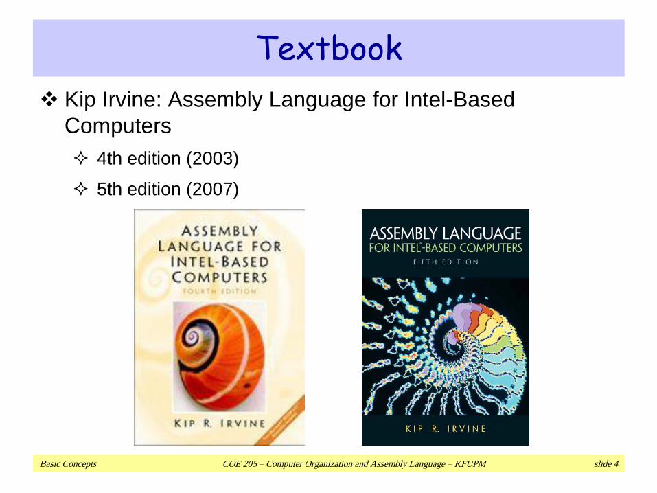
Textbook
Kip Irvine: Assembly Language for Intel-Based
Computers
4th edition (2003)
5th edition (2007)
Basic Concepts COE 205 – Computer Organization and Assembly Language – KFUPM slide 5
Course ObjectivesAfter successfully completing the course, students will be able to:
Describe the basic components of a computer system, its instruction
set architecture and its basic fetch-execute cycle operation.
Describe how data is represented in a computer and recognize
when overflow occurs.
Recognize the basics of assembly language programming including
addressing modes.
Analyze, design, implement, and test assembly language programs.
Recognize, analyze, and design the basic components of a simple
CPU including datapath and control unit design alternatives.
Basic Concepts COE 205 – Computer Organization and Assembly Language – KFUPM slide 6
Course Learning Outcomes
Ability to analyze, design, implement, and test assembly
language programs.
Ability to use tools and skills in analyzing and debugging
assembly language programs.
Ability to design the datapath and control unit of a simple
CPU.
Ability to demonstrate self-learning capability.
Ability to work in a team.
Basic Concepts COE 205 – Computer Organization and Assembly Language – KFUPM slide 7
Required Background
The student should already be able to program
confidently in at least one high-level programming
language, such as Java or C.
Prerequisite
COE 202: Fundamentals of computer engineering
ICS 102: Introduction to computing
Only students with computer engineering major should
be registered in this course.

Basic Concepts COE 205 – Computer Organization and Assembly Language – KFUPM slide 8
Grading Policy Discussions & Reflections 5%
Programming Assignments 10%
Quizzes 10%
Exam I 15% (Sun. March 28, 2010)
Exam II 20% (Th. May 20, 2010)
Laboratory 20%
Final 20%
Attendance will be taken regularly.
Excuses for officially authorized absences must be presented no later than one week following resumption of class attendance.
Late assignments will be accepted but you will be penalized 10% per each late day.
A student caught cheating in any of the assignments will get 0 out of 10%.
No makeup will be made for missing Quizzes or Exams.
Basic Concepts COE 205 – Computer Organization and Assembly Language – KFUPM slide 9
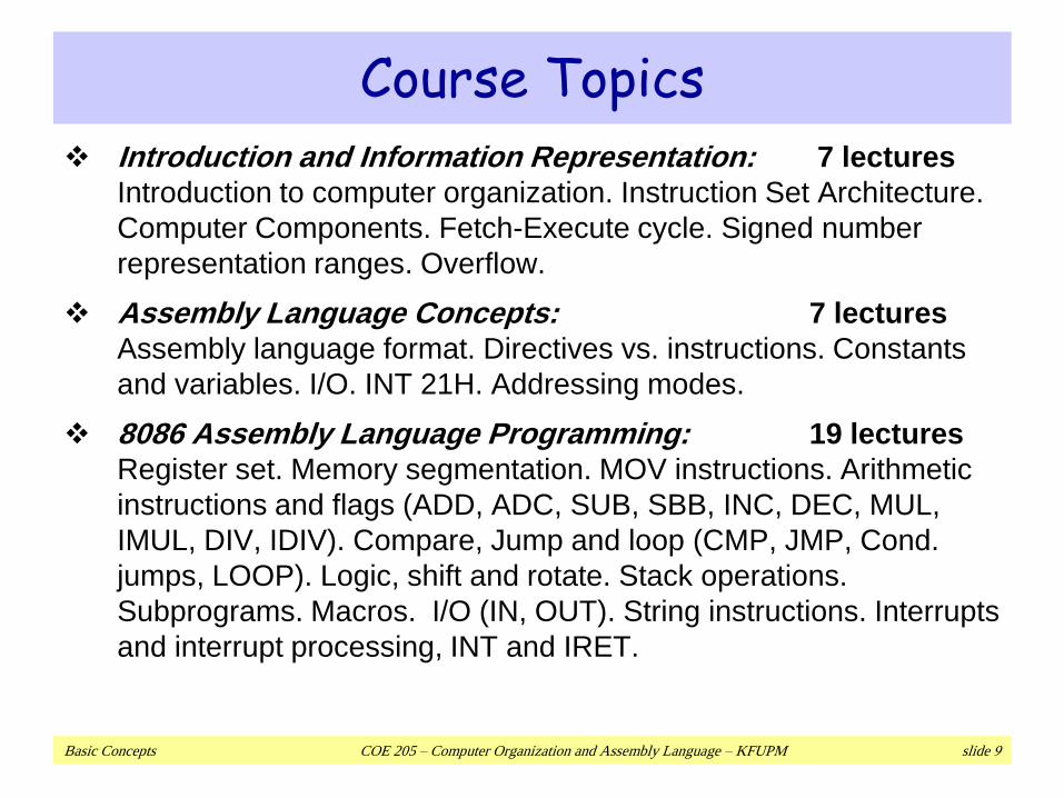
Course Topics Introduction and Information Representation: 7 lectures
Introduction to computer organization. Instruction Set Architecture.
Computer Components. Fetch-Execute cycle. Signed number
representation ranges. Overflow.
Assembly Language Concepts: 7 lectures
Assembly language format. Directives vs. instructions. Constants
and variables. I/O. INT 21H. Addressing modes.
8086 Assembly Language Programming: 19 lectures
Register set. Memory segmentation. MOV instructions. Arithmetic
instructions and flags (ADD, ADC, SUB, SBB, INC, DEC, MUL,
IMUL, DIV, IDIV). Compare, Jump and loop (CMP, JMP, Cond.
jumps, LOOP). Logic, shift and rotate. Stack operations.
Subprograms. Macros. I/O (IN, OUT). String instructions. Interrupts
and interrupt processing, INT and IRET.
Basic Concepts COE 205 – Computer Organization and Assembly Language – KFUPM slide 10
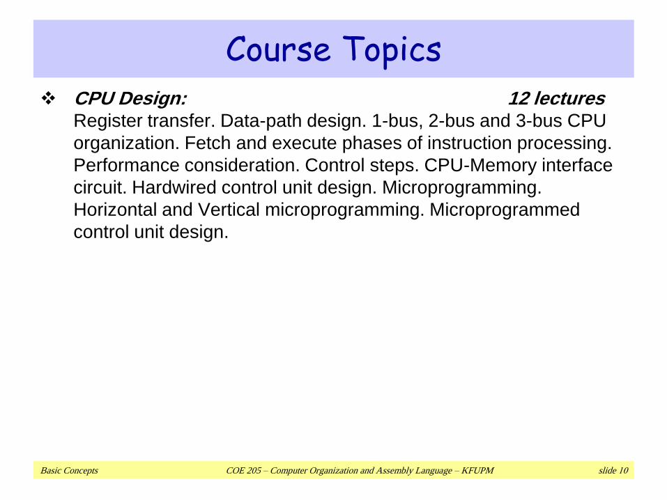
Course Topics CPU Design: 12 lectures
Register transfer. Data-path design. 1-bus, 2-bus and 3-bus CPU
organization. Fetch and execute phases of instruction processing.
Performance consideration. Control steps. CPU-Memory interface
circuit. Hardwired control unit design. Microprogramming.
Horizontal and Vertical microprogramming. Microprogrammed
control unit design.
Basic Concepts COE 205 – Computer Organization and Assembly Language – KFUPM slide 11
Next …
Welcome to COE 205
Assembly-, Machine-, and High-Level Languages
Assembly Language Programming Tools
Programmer’s View of a Computer System
Basic Computer Organization
Basic Concepts COE 205 – Computer Organization and Assembly Language – KFUPM slide 12
Some Important Questions to Ask
What is Assembly Language?
Why Learn Assembly Language?
What is Machine Language?
How is Assembly related to Machine Language?
What is an Assembler?
How is Assembly related to High-Level Language?
Is Assembly Language portable?
Basic Concepts COE 205 – Computer Organization and Assembly Language – KFUPM slide 13
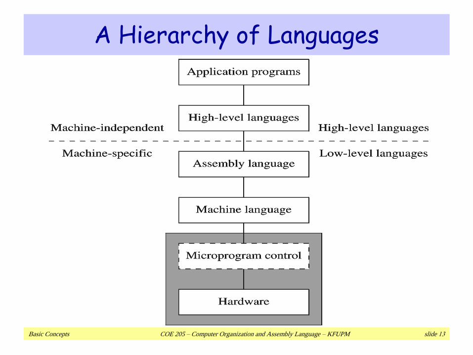
A Hierarchy of Languages
Basic Concepts COE 205 – Computer Organization and Assembly Language – KFUPM slide 14
Assembly and Machine Language Machine language
Native to a processor: executed directly by hardware
Instructions consist of binary code: 1s and 0s
Assembly language
A programming language that uses symbolic names to represent
operations, registers and memory locations.
Slightly higher-level language
Readability of instructions is better than machine language
One-to-one correspondence with machine language instructions
Assemblers translate assembly to machine code
Compilers translate high-level programs to machine code
Either directly, or
Indirectly via an assembler
Basic Concepts COE 205 – Computer Organization and Assembly Language – KFUPM slide 15
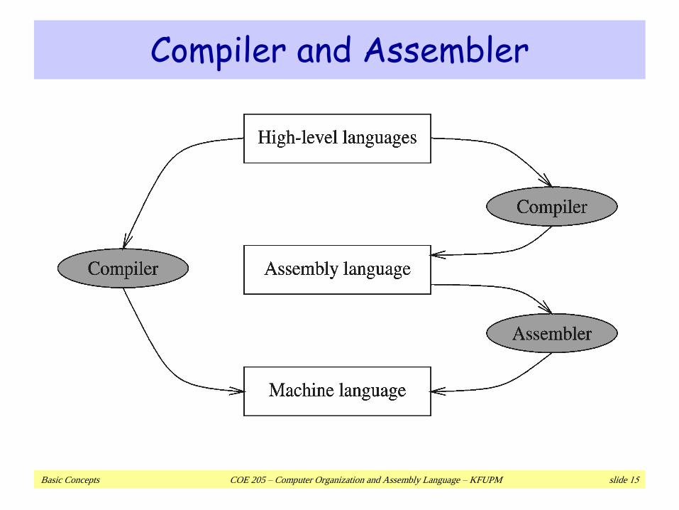
Compiler and Assembler
Basic Concepts COE 205 – Computer Organization and Assembly Language – KFUPM slide 16
Instructions and Machine Language
Each command of a program is called an instruction (it
instructs the computer what to do).
Computers only deal with binary data, hence the
instructions must be in binary format (0s and 1s) .
The set of all instructions (in binary form) makes up the
computer's machine language. This is also referred to as
the instruction set.
Basic Concepts COE 205 – Computer Organization and Assembly Language – KFUPM slide 17
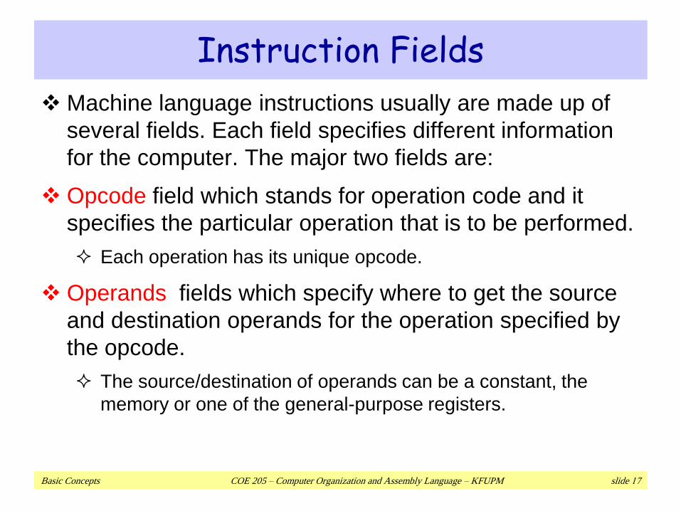
Instruction Fields
Machine language instructions usually are made up of
several fields. Each field specifies different information
for the computer. The major two fields are:
Opcode field which stands for operation code and it
specifies the particular operation that is to be performed.
Each operation has its unique opcode.
Operands fields which specify where to get the source
and destination operands for the operation specified by
the opcode.
The source/destination of operands can be a constant, the
memory or one of the general-purpose registers.
Basic Concepts COE 205 – Computer Organization and Assembly Language – KFUPM slide 18
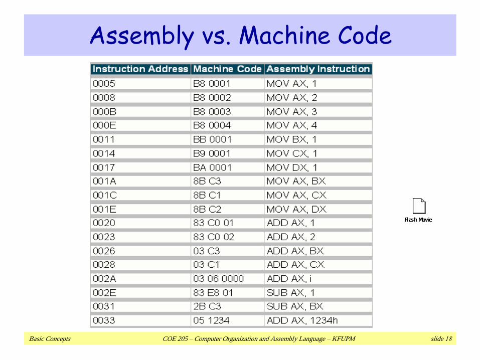
Assembly vs. Machine Code
Basic Concepts COE 205 – Computer Organization and Assembly Language – KFUPM slide 19
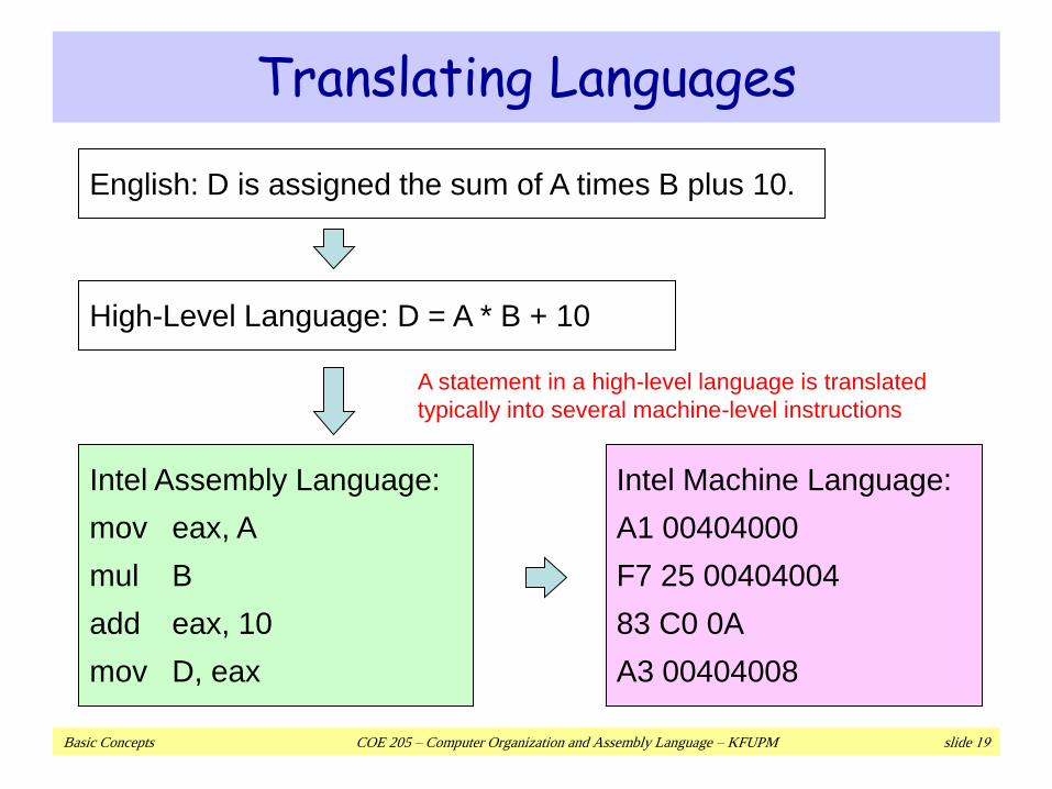
Translating Languages
English: D is assigned the sum of A times B plus 10.
High-Level Language: D = A * B + 10
Intel Assembly Language:
mov eax, A
mul B
add eax, 10
mov D, eax
Intel Machine Language:
A1 00404000
F7 25 00404004
83 C0 0A
A3 00404008
A statement in a high-level language is translated
typically into several machine-level instructions
Basic Concepts COE 205 – Computer Organization and Assembly Language – KFUPM slide 20
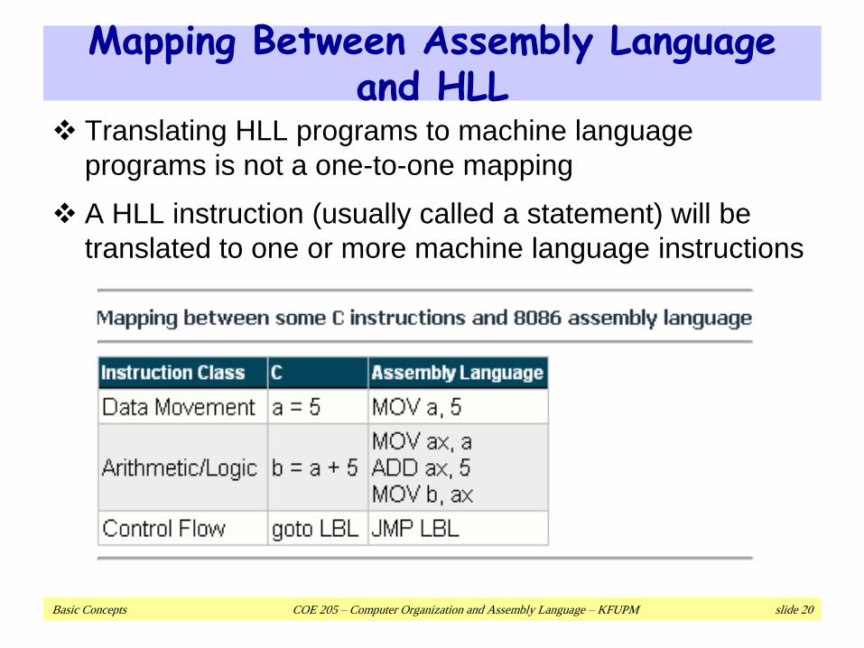
Mapping Between Assembly Language and HLL
Translating HLL programs to machine language
programs is not a one-to-one mapping
A HLL instruction (usually called a statement) will be
translated to one or more machine language instructions
Basic Concepts COE 205 – Computer Organization and Assembly Language – KFUPM slide 21
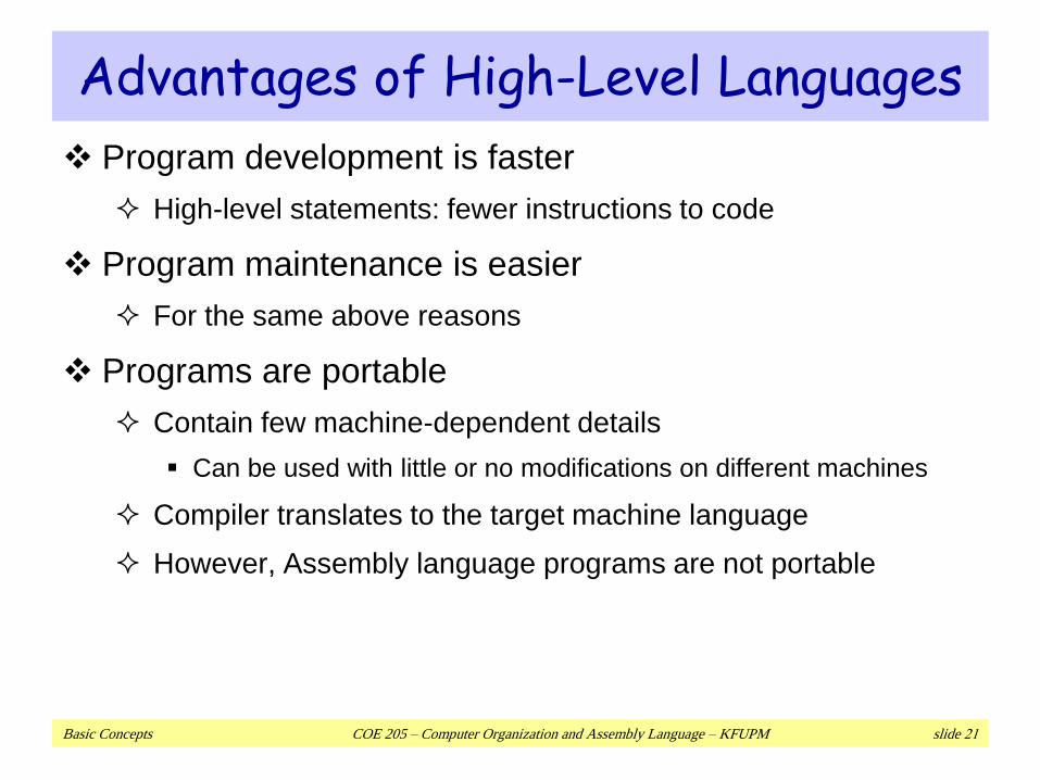
Advantages of High-Level Languages
Program development is faster
High-level statements: fewer instructions to code
Program maintenance is easier
For the same above reasons
Programs are portable
Contain few machine-dependent details
Can be used with little or no modifications on different machines
Compiler translates to the target machine language
However, Assembly language programs are not portable
Basic Concepts COE 205 – Computer Organization and Assembly Language – KFUPM slide 22
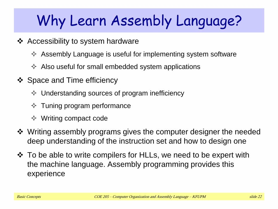
Why Learn Assembly Language? Accessibility to system hardware
Assembly Language is useful for implementing system software
Also useful for small embedded system applications
Space and Time efficiency
Understanding sources of program inefficiency
Tuning program performance
Writing compact code
Writing assembly programs gives the computer designer the needed
deep understanding of the instruction set and how to design one
To be able to write compilers for HLLs, we need to be expert with
the machine language. Assembly programming provides this
experience
Basic Concepts COE 205 – Computer Organization and Assembly Language – KFUPM slide 23
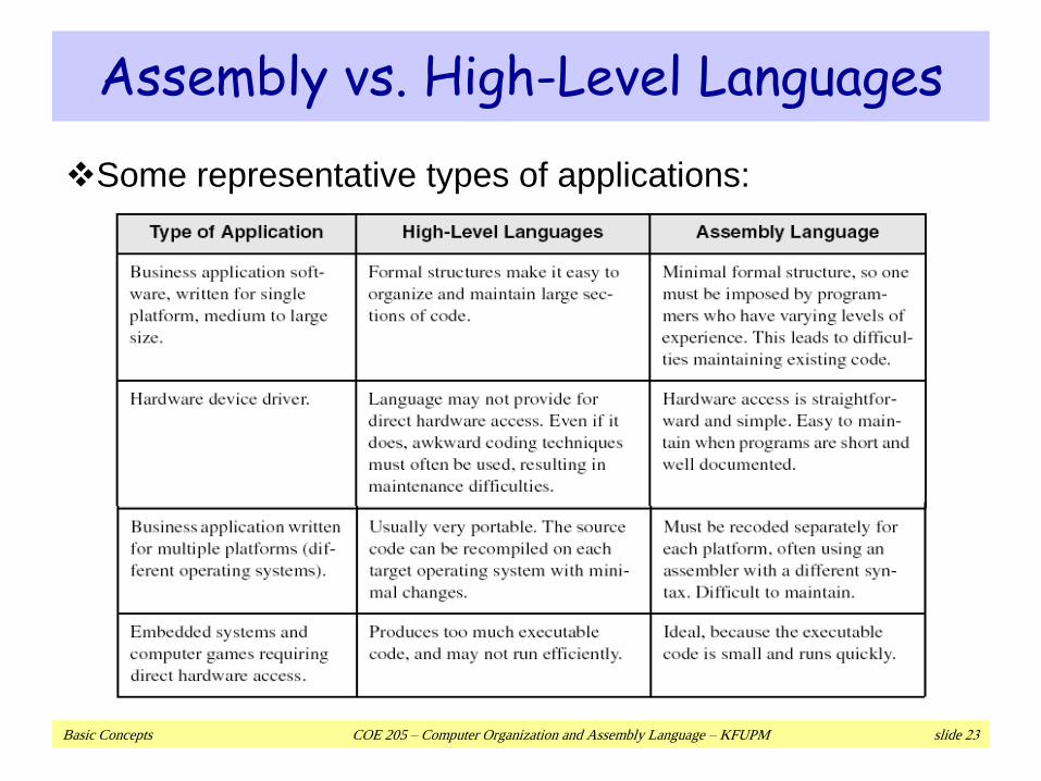
Assembly vs. High-Level Languages
Some representative types of applications:
Basic Concepts COE 205 – Computer Organization and Assembly Language – KFUPM slide 24
Next …
Welcome to COE 205
Assembly-, Machine-, and High-Level Languages
Assembly Language Programming Tools
Programmer’s View of a Computer System
Basic Computer Organization

Basic Concepts COE 205 – Computer Organization and Assembly Language – KFUPM slide 25
Assembler
Software tools are needed for editing, assembling,
linking, and debugging assembly language programs
An assembler is a program that converts source-code
programs written in assembly language into object files
in machine language
Popular assemblers have emerged over the years for the
Intel family of processors. These include …
TASM (Turbo Assembler from Borland)
NASM (Netwide Assembler for both Windows and Linux), and
GNU assembler distributed by the free software foundation
We will use MASM (Macro Assembler from Microsoft)
Basic Concepts COE 205 – Computer Organization and Assembly Language – KFUPM slide 26
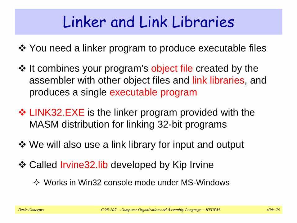
Linker and Link Libraries
You need a linker program to produce executable files
It combines your program's object file created by the
assembler with other object files and link libraries, and
produces a single executable program
LINK32.EXE is the linker program provided with the
MASM distribution for linking 32-bit programs
We will also use a link library for input and output
Called Irvine32.lib developed by Kip Irvine
Works in Win32 console mode under MS-Windows
Basic Concepts COE 205 – Computer Organization and Assembly Language – KFUPM slide 27
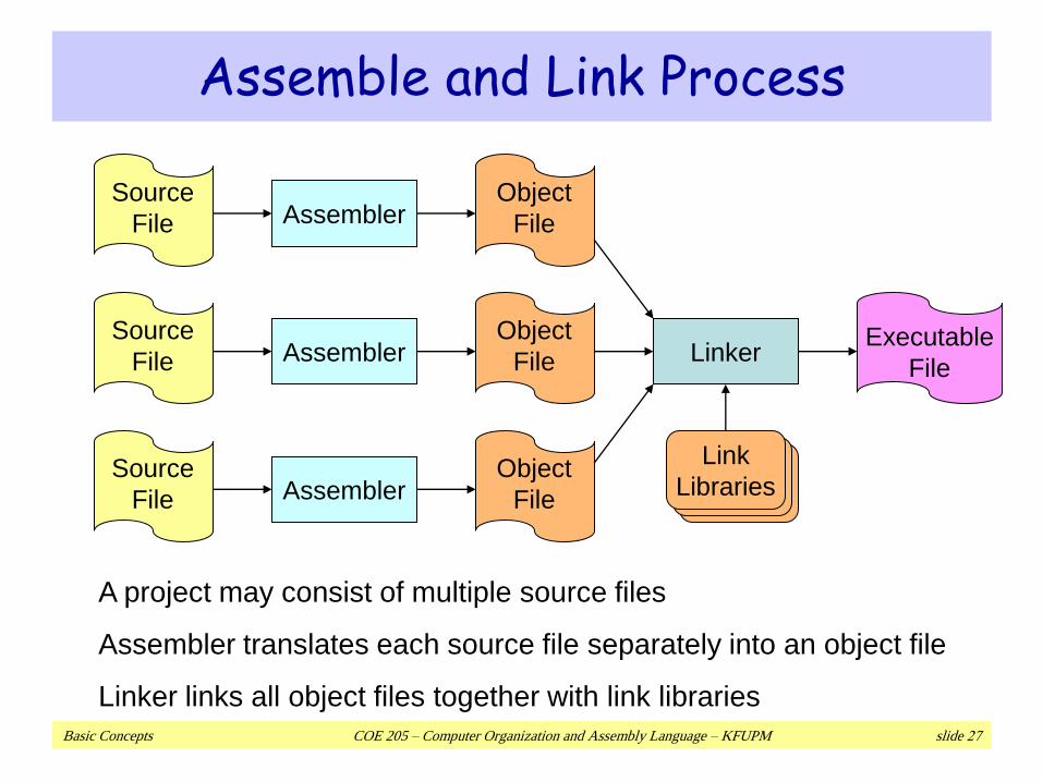
Assemble and Link Process
Source
File
Source
File
Source
File
AssemblerObject
File
AssemblerObject
File
AssemblerObject
File
LinkerExecutable
File
Link
Libraries
A project may consist of multiple source files
Assembler translates each source file separately into an object file
Linker links all object files together with link libraries
Basic Concepts COE 205 – Computer Organization and Assembly Language – KFUPM slide 28
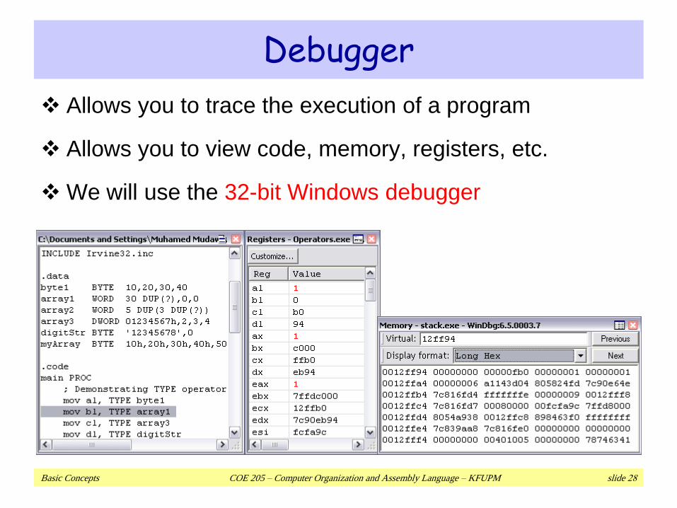
Debugger
Allows you to trace the execution of a program
Allows you to view code, memory, registers, etc.
We will use the 32-bit Windows debugger
Basic Concepts COE 205 – Computer Organization and Assembly Language – KFUPM slide 29
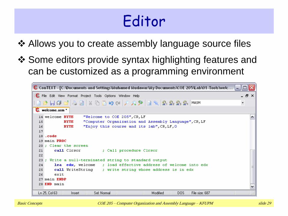
Editor
Allows you to create assembly language source files
Some editors provide syntax highlighting features and
can be customized as a programming environment
Basic Concepts COE 205 – Computer Organization and Assembly Language – KFUPM slide 30
Next …
Welcome to COE 205
Assembly-, Machine-, and High-Level Languages
Assembly Language Programming Tools
Programmer’s View of a Computer System
Basic Computer Organization
Basic Concepts COE 205 – Computer Organization and Assembly Language – KFUPM slide 31
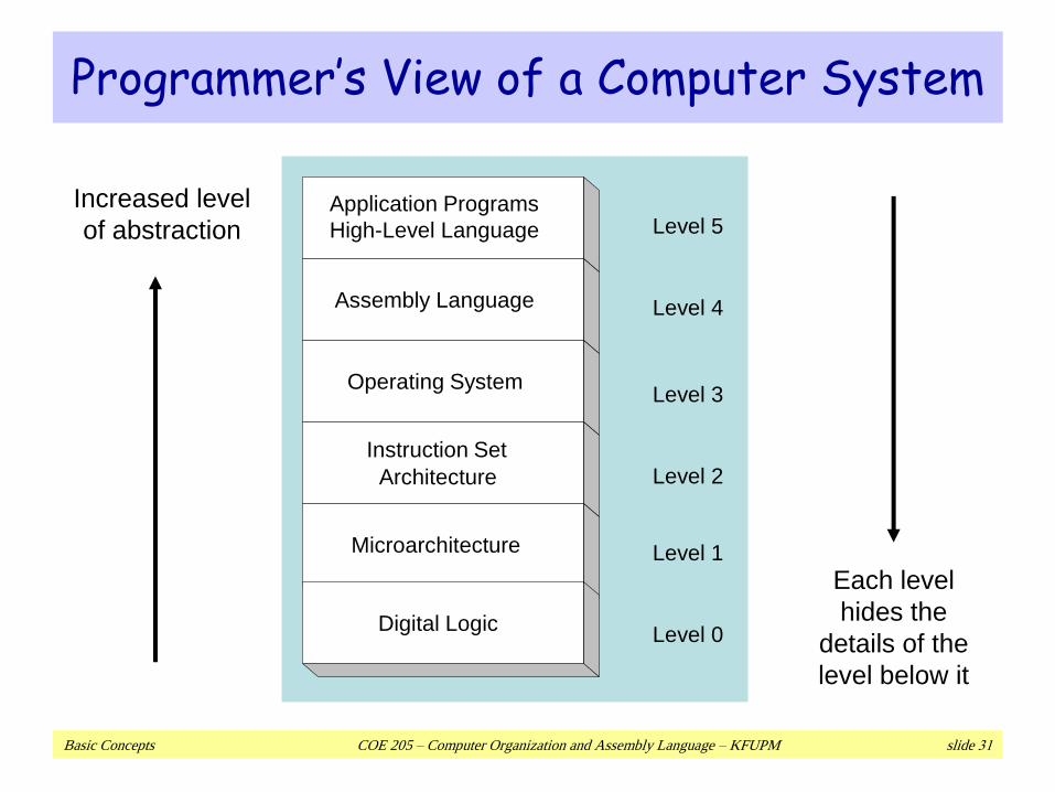
Programmer’s View of a Computer System
Application Programs
High-Level Language
Assembly Language
Operating System
Instruction Set
Architecture
Microarchitecture
Digital LogicLevel 0
Level 1
Level 2
Level 3
Level 4
Level 5
Increased level
of abstraction
Each level
hides the
details of the
level below it
Basic Concepts COE 205 – Computer Organization and Assembly Language – KFUPM slide 32
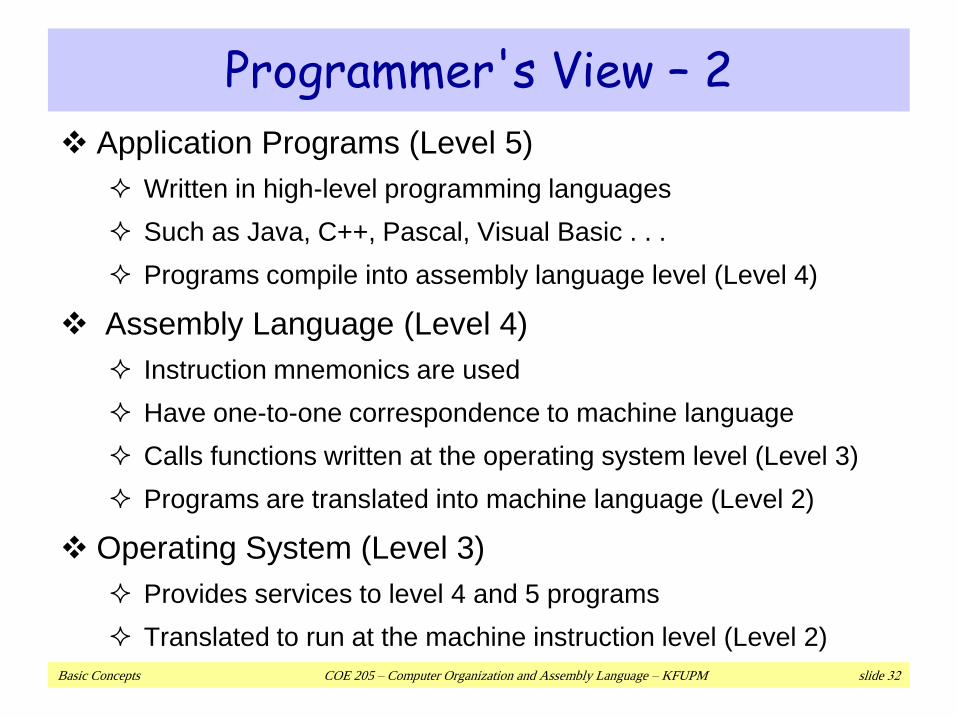
Programmer's View – 2
Application Programs (Level 5)
Written in high-level programming languages
Such as Java, C++, Pascal, Visual Basic . . .
Programs compile into assembly language level (Level 4)
Assembly Language (Level 4)
Instruction mnemonics are used
Have one-to-one correspondence to machine language
Calls functions written at the operating system level (Level 3)
Programs are translated into machine language (Level 2)
Operating System (Level 3)
Provides services to level 4 and 5 programs
Translated to run at the machine instruction level (Level 2)
Basic Concepts COE 205 – Computer Organization and Assembly Language – KFUPM slide 33
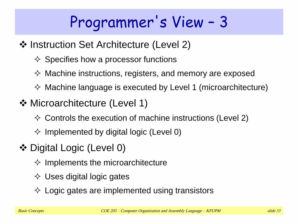
Programmer's View – 3
Instruction Set Architecture (Level 2)
Specifies how a processor functions
Machine instructions, registers, and memory are exposed
Machine language is executed by Level 1 (microarchitecture)
Microarchitecture (Level 1)
Controls the execution of machine instructions (Level 2)
Implemented by digital logic (Level 0)
Digital Logic (Level 0)
Implements the microarchitecture
Uses digital logic gates
Logic gates are implemented using transistors
Basic Concepts COE 205 – Computer Organization and Assembly Language – KFUPM slide 34
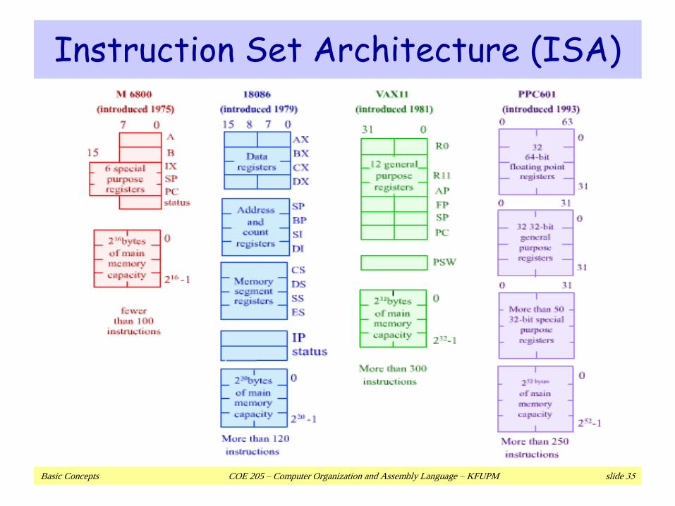
Instruction Set Architecture (ISA)
Collection of assembly/machine instruction set of the
machine
Machine resources that can be managed with these
instructions
Memory
Programmer-accessible registers.
Provides a hardware/software interface
Basic Concepts COE 205 – Computer Organization and Assembly Language – KFUPM slide 35
Instruction Set Architecture (ISA)
Basic Concepts COE 205 – Computer Organization and Assembly Language – KFUPM slide 36
Next …
Welcome to COE 205
Assembly-, Machine-, and High-Level Languages
Assembly Language Programming Tools
Programmer’s View of a Computer System
Basic Computer Organization
Basic Concepts COE 205 – Computer Organization and Assembly Language – KFUPM slide 37
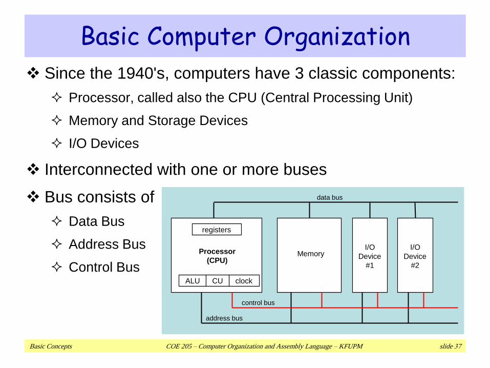
Basic Computer Organization
Since the 1940's, computers have 3 classic components:
Processor, called also the CPU (Central Processing Unit)
Memory and Storage Devices
I/O Devices
Interconnected with one or more buses
Bus consists of
Data Bus
Address Bus
Control Bus
Processor
(CPU)Memory
registers
ALU clock
I/O
Device
#1
I/O
Device
#2
data bus
control bus
address bus
CU
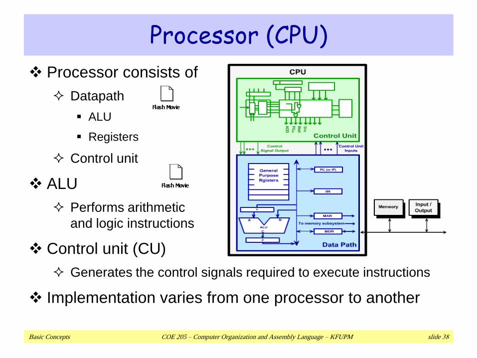
Basic Concepts COE 205 – Computer Organization and Assembly Language – KFUPM slide 38
Processor consists of
Datapath
ALU
Registers
Control unit
ALU
Performs arithmetic
and logic instructions
Control unit (CU)
Generates the control signals required to execute instructions
Implementation varies from one processor to another
Processor (CPU)
Basic Concepts COE 205 – Computer Organization and Assembly Language – KFUPM slide 39
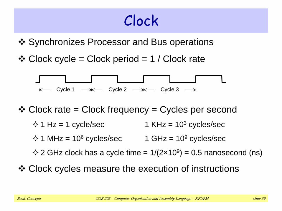
Synchronizes Processor and Bus operations
Clock cycle = Clock period = 1 / Clock rate
Clock rate = Clock frequency = Cycles per second
1 Hz = 1 cycle/sec 1 KHz = 103 cycles/sec
1 MHz = 106 cycles/sec 1 GHz = 109 cycles/sec
2 GHz clock has a cycle time = 1/(2×109) = 0.5 nanosecond (ns)
Clock cycles measure the execution of instructions
Clock
Cycle 1 Cycle 2 Cycle 3
Basic Concepts COE 205 – Computer Organization and Assembly Language – KFUPM slide 40
Memory
Ordered sequence of bytes
The sequence number is called the memory address
Byte addressable memory
Each byte has a unique address
Supported by almost all processors
Physical address space
Determined by the address bus width
Pentium has a 32-bit address bus
Physical address space = 4GB = 232 bytes
Itanium with a 64-bit address bus can support
Up to 264 bytes of physical address space
Basic Concepts COE 205 – Computer Organization and Assembly Language – KFUPM slide 41
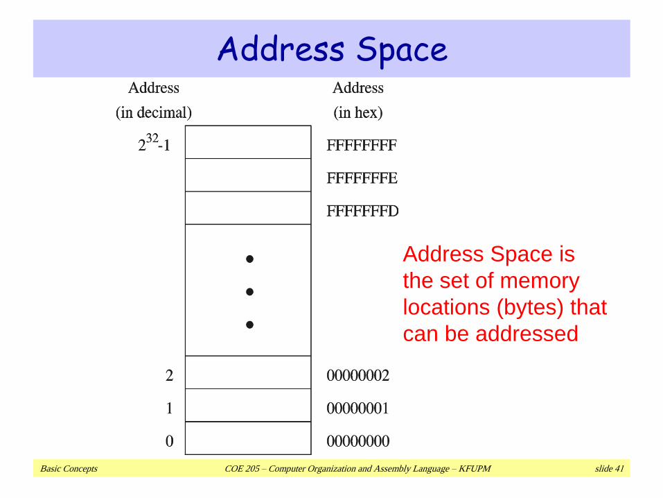
Address Space
Address Space is
the set of memory
locations (bytes) that
can be addressed
Basic Concepts COE 205 – Computer Organization and Assembly Language – KFUPM slide 42
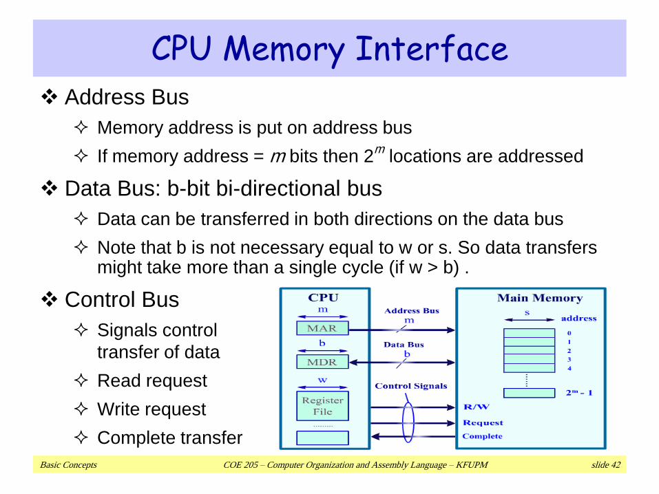
CPU Memory Interface Address Bus
Memory address is put on address bus
If memory address = m bits then 2m
locations are addressed
Data Bus: b-bit bi-directional bus
Data can be transferred in both directions on the data bus
Note that b is not necessary equal to w or s. So data transfers might take more than a single cycle (if w > b) .
Control Bus
Signals control
transfer of data
Read request
Write request
Complete transfer
Basic Concepts COE 205 – Computer Organization and Assembly Language – KFUPM slide 43
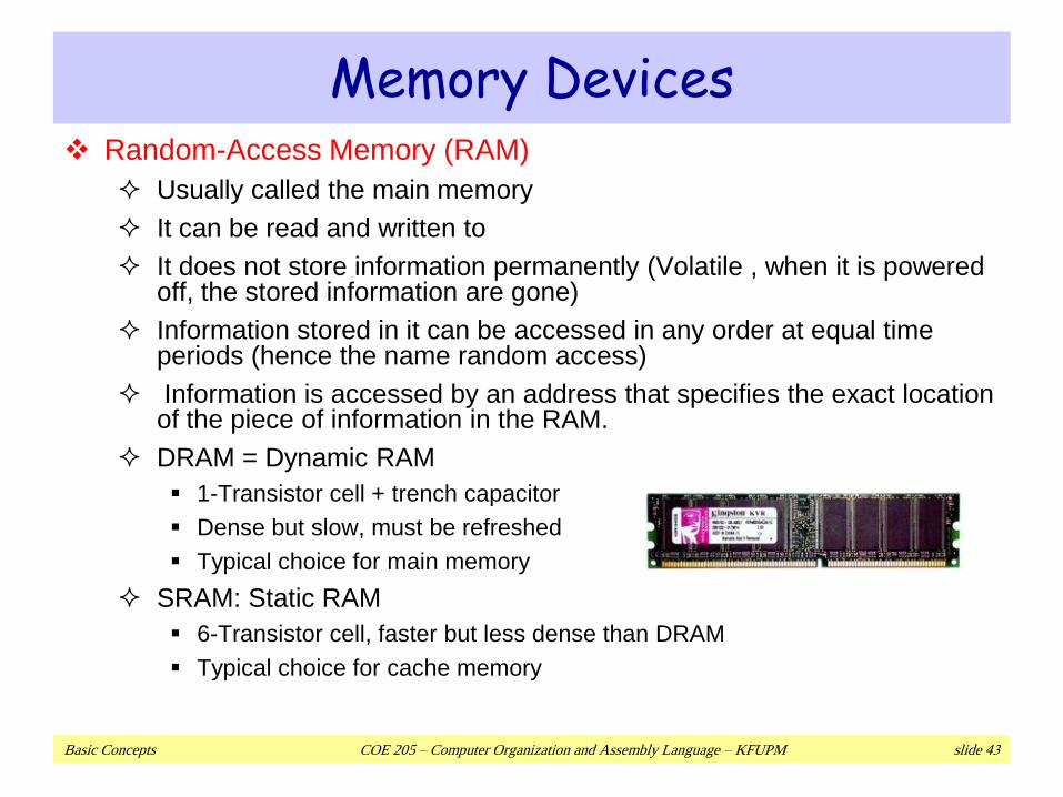
Memory Devices Random-Access Memory (RAM)
Usually called the main memory
It can be read and written to
It does not store information permanently (Volatile , when it is powered off, the stored information are gone)
Information stored in it can be accessed in any order at equal time periods (hence the name random access)
Information is accessed by an address that specifies the exact location of the piece of information in the RAM.
DRAM = Dynamic RAM
1-Transistor cell + trench capacitor
Dense but slow, must be refreshed
Typical choice for main memory
SRAM: Static RAM
6-Transistor cell, faster but less dense than DRAM
Typical choice for cache memory
Basic Concepts COE 205 – Computer Organization and Assembly Language – KFUPM slide 44
Memory Devices
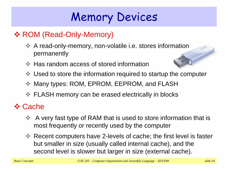
ROM (Read-Only-Memory)
A read-only-memory, non-volatile i.e. stores information
permanently
Has random access of stored information
Used to store the information required to startup the computer
Many types: ROM, EPROM, EEPROM, and FLASH
FLASH memory can be erased electrically in blocks
Cache
A very fast type of RAM that is used to store information that is
most frequently or recently used by the computer
Recent computers have 2-levels of cache; the first level is faster
but smaller in size (usually called internal cache), and the
second level is slower but larger in size (external cache).
Basic Concepts COE 205 – Computer Organization and Assembly Language – KFUPM slide 45
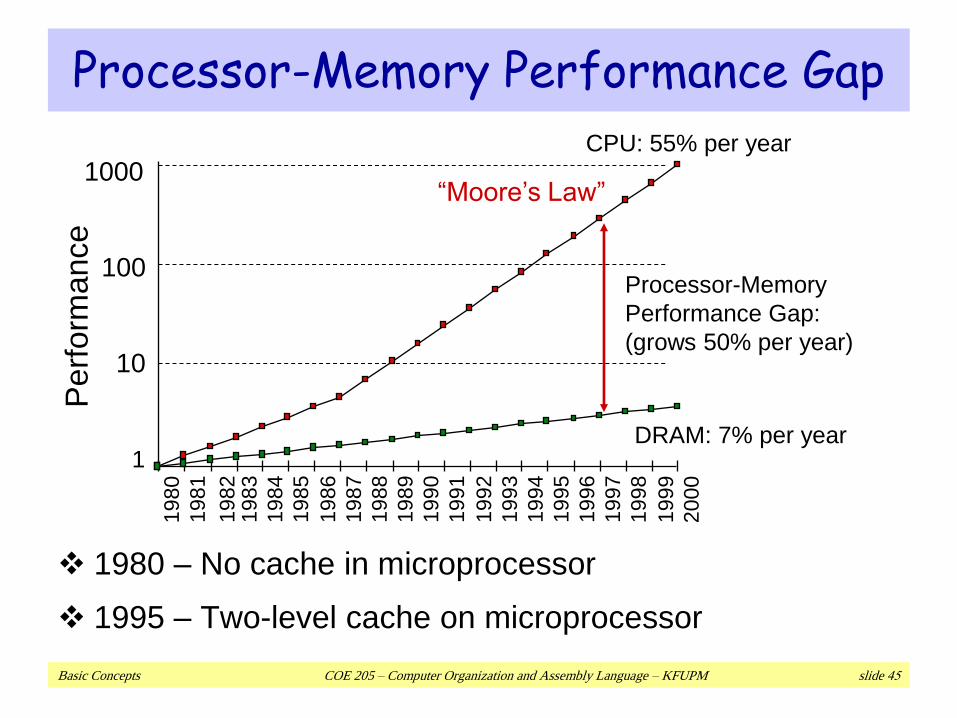
Processor-Memory Performance Gap
1980 – No cache in microprocessor
1995 – Two-level cache on microprocessor
CPU: 55% per year
DRAM: 7% per year1
10
100
10001
98
0
19
81
19
83
19
84
1985
19
86
19
87
19
88
19
89
19
90
19
91
19
92
19
93
19
94
19
95
19
96
19
97
19
98
19
99
20
00
19
82
Processor-Memory
Performance Gap:
(grows 50% per year)
Perf
orm
ance
“Moore’s Law”
Basic Concepts COE 205 – Computer Organization and Assembly Language – KFUPM slide 46
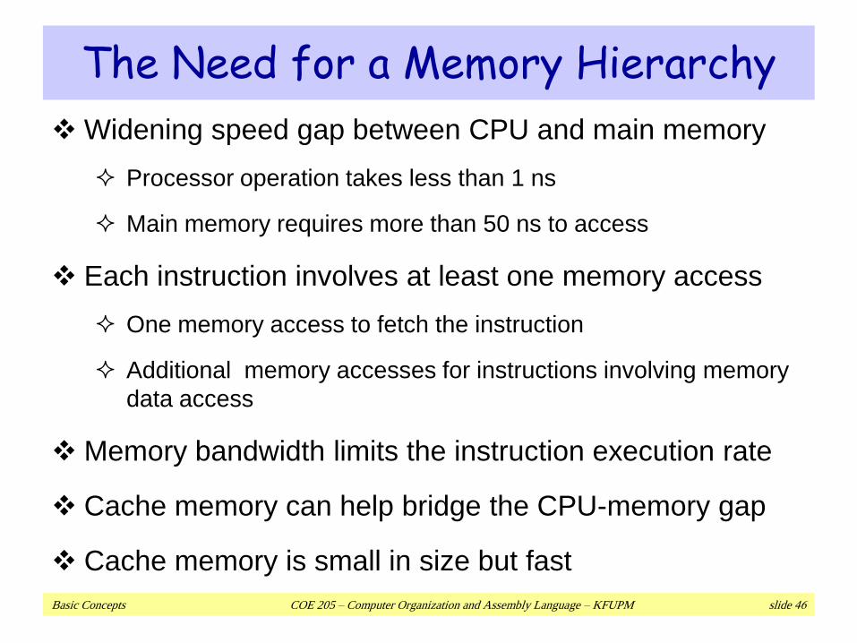
The Need for a Memory Hierarchy
Widening speed gap between CPU and main memory
Processor operation takes less than 1 ns
Main memory requires more than 50 ns to access
Each instruction involves at least one memory access
One memory access to fetch the instruction
Additional memory accesses for instructions involving memory
data access
Memory bandwidth limits the instruction execution rate
Cache memory can help bridge the CPU-memory gap
Cache memory is small in size but fast
Basic Concepts COE 205 – Computer Organization and Assembly Language – KFUPM slide 47
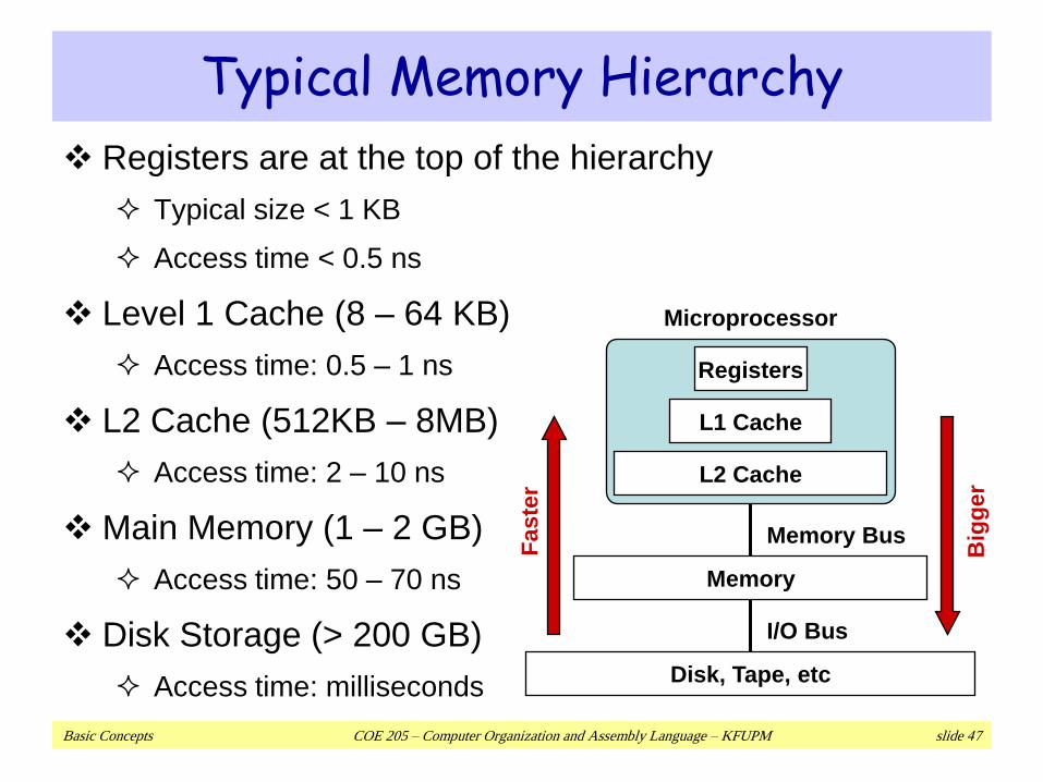
Typical Memory Hierarchy
Registers are at the top of the hierarchy
Typical size < 1 KB
Access time < 0.5 ns
Level 1 Cache (8 – 64 KB)
Access time: 0.5 – 1 ns
L2 Cache (512KB – 8MB)
Access time: 2 – 10 ns
Main Memory (1 – 2 GB)
Access time: 50 – 70 ns
Disk Storage (> 200 GB)
Access time: milliseconds
Microprocessor
Registers
L1 Cache
L2 Cache
Memory
Disk, Tape, etc
Memory Bus
I/O Bus
Faste
r
Big
ger
Basic Concepts COE 205 – Computer Organization and Assembly Language – KFUPM slide 48
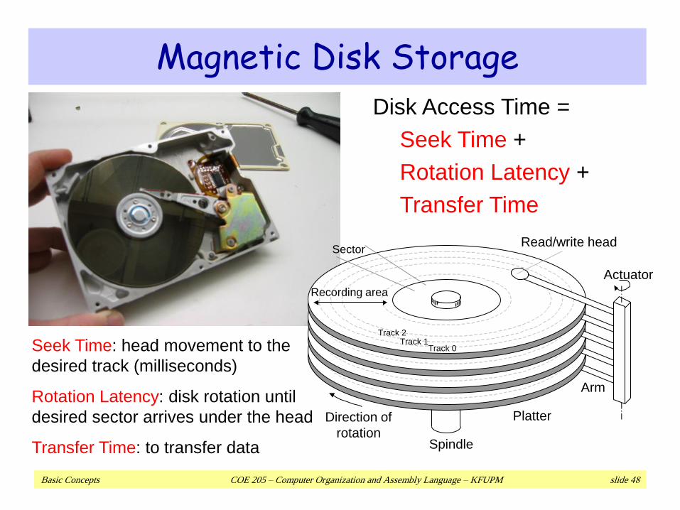
Magnetic Disk Storage
Track 0Track 1
Sector
Recording area
Spindle
Direction of
rotation
Platter
Read/write head
Actuator
Arm
Track 2
Disk Access Time =
Seek Time +
Rotation Latency +
Transfer Time
Seek Time: head movement to the
desired track (milliseconds)
Rotation Latency: disk rotation until
desired sector arrives under the head
Transfer Time: to transfer data
Basic Concepts COE 205 – Computer Organization and Assembly Language – KFUPM slide 49
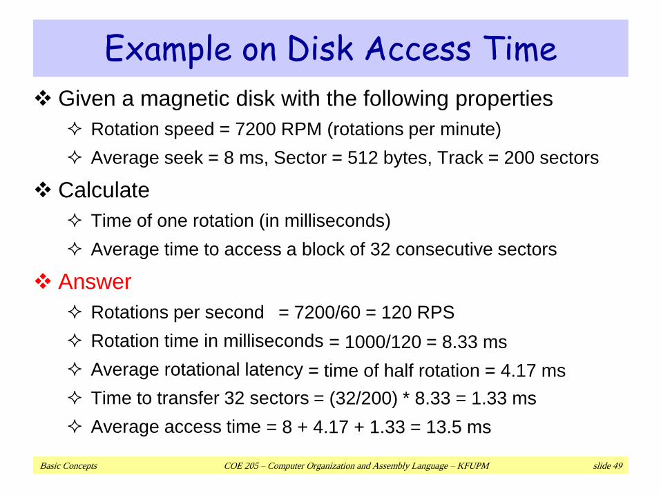
Example on Disk Access Time
Given a magnetic disk with the following properties
Rotation speed = 7200 RPM (rotations per minute)
Average seek = 8 ms, Sector = 512 bytes, Track = 200 sectors
Calculate
Time of one rotation (in milliseconds)
Average time to access a block of 32 consecutive sectors
Answer
Rotations per second
Rotation time in milliseconds
Average rotational latency
Time to transfer 32 sectors
Average access time
= 7200/60 = 120 RPS
= 1000/120 = 8.33 ms
= time of half rotation = 4.17 ms
= (32/200) * 8.33 = 1.33 ms
= 8 + 4.17 + 1.33 = 13.5 ms