Embed Size (px)
Citation preview

IM-P403-35 AB Issue 8 1
BC3100Controller
Installation and Maintenance Instructions
IM-P403-35AB Issue 8
4033350/8
�� ����������� ����������
�� �������������� ����������
�� �����������
�� ������� �� ��� ����������
�� ������ �������
�� �����������
� !��������
"� #����������
$� %���� ������
Printed in the UK © Copyright 2005
�
����
����
��������
����
��������
�����
��
��
����
������
���
�
� �
��
�
��
�
Archive

IM-P403-35 AB Issue 82
Archive
IM-P403-35 AB Issue 8 3
�������������� ������������Your attention is drawn to Safety Information Sheet IM-GCM-10 as well as to anyNational or local regulations.
Safe operation of the product depends on it being properly installed, commissionedand maintained by a qualified person in compliance with the operating instructions.
It is essential to comply with general installation and safety instructions for pipelineand plant construction, as well as to make proper use of tools and safety equipment.
The product is designed and constructed to withstand the forces encounteredduring normal use. Use of the product for any other purpose, or failure to install theproduct in accordance with these Installation and Maintenance Instructions, could causedamage to the product, will invalidate the marking, and may cause injury or fatalityto personnel.
WarningIsolate the mains supply before unplugging the controller since hazardous voltages willbe exposed on the controller base. This product complies with the requirementsof Electromagnetic Compatibility Directive 89 /336 /EEC by meeting the standards of:
- EN 61326 : 1997 A1 + A2 Emissions Class B equipment Table 4.- EN 61326 : 1997 A1 + A2 Immunity Class A equipment Table 1.
The following conditions should be avoided as they may create interference abovethe limits specified in EN 61326 (Immunity) if:
- The product or its wiring is located near a radio transmitter.
- Excessive electrical noise occurs on the mains supply. Power line protectors (ac)should be installed if mains supply noise is likely. Protectors can combine filtering,suppression, surge and spike arrestors.
- Cellular telephones and mobile radios may cause interference if used withinapproximately 1 metre (39") of the product or its wiring. The actual separation distancenecessary will vary according to the surroundings of the installation and the powerof the transmitter.
If this product is not used in the manner specified by this IMI, then the protectionprovided may be impaired.Arch
ive
IM-P403-35 AB Issue 84
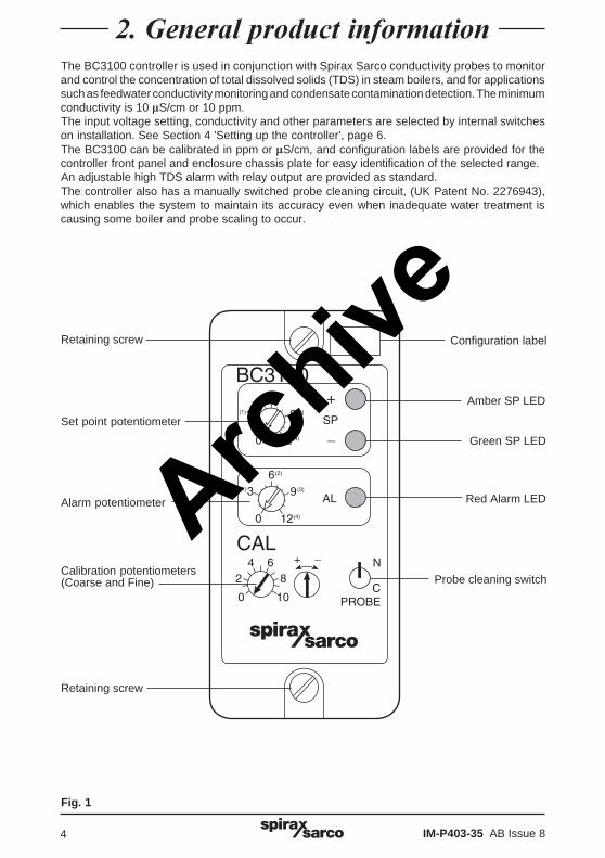
�����������������������������The BC3100 controller is used in conjunction with Spirax Sarco conductivity probes to monitorand control the concentration of total dissolved solids (TDS) in steam boilers, and for applicationssuch as feedwater conductivity monitoring and condensate contamination detection. The minimumconductivity is 10 �S/cm or 10 ppm.The input voltage setting, conductivity and other parameters are selected by internal switcheson installation. See Section 4 'Setting up the controller', page 6.The BC3100 can be calibrated in ppm or �S/cm, and configuration labels are provided for thecontroller front panel and enclosure chassis plate for easy identification of the selected range.An adjustable high TDS alarm with relay output are provided as standard.The controller also has a manually switched probe cleaning circuit, (UK Patent No. 2276943),which enables the system to maintain its accuracy even when inadequate water treatment iscausing some boiler and probe scaling to occur.
Fig. 1
�
����
����
��������
����
��������
�����
��
��
����
������
���
�
� �
��
�
��
�
Configuration labelRetaining screw
Set point potentiometer
Alarm potentiometer
Calibration potentiometers(Coarse and Fine)
Amber SP LED
Green SP LED
Red Alarm LED
Probe cleaning switch
Retaining screw
Archive
IM-P403-35 AB Issue 8 5
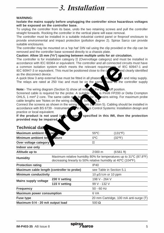
������������WARNING:Isolate the mains supply before unplugging the controller since hazardous voltageswill be exposed on the controller base.To unplug the controller from its base, undo the two retaining screws and pull the controllerstraight forwards. Rocking the controller in the vertical plane will ease removal.The controller must be installed in a suitable industrial control panel or fireproof enclosure toprovide environmental and impact protection (pollution degree 2). Spirax Sarco can providesuitable enclosures.The controller may be mounted on a 'top hat' DIN rail using the clip provided or the clip can beremoved and the controller base screwed directly to a chassis plate.Caution: Allow 15 mm (5/8") spacing between multiple units for air circulation.The controller is for installation category �� (Overvoltage category) and must be installed inaccordance with IEC 60364 or equivalent. The controller and all connected circuits must havea common isolation system which meets the relevant requirements of IEC 60947-1 andIEC 60947-3 or equivalent. This must be positioned close to the controller and clearly identifiedas the disconnect device.A quick blow 3 amp external fuse must be fitted in all phases of the controller and relay supply.The relays are rated at 250 Vac and must be on the same phase as the controller supply
Note:- The wiring diagram (Section 5) show all relays in the power off position.Screened cable is required for the probe. A suitable cable is Pirelli FP200 or Delta CromptonOHLS, 1 mm2 2 core. The same cable may be used for the mains wiring. For maximum probecable lengths see 'Notes on the wiring diagram', Section 5.1.Connect the screens as shown in the wiring diagram (Section 5). Cabling should be installed inaccordance with BS 6739 - Instrumentation in Process Control Systems: Installation design andpractice or local equivalent.If the product is not used in the manner specified in this IMI, then the protectionprovided may be impaired.
Technical dataMaximum ambient temperature 55°C (131°F)
Minimum ambient temperature 0°C (32°F)
Over voltage category ��Indoor use only
Altitude up to 2000 m (6561 ft)
Humidity Maximum relative humidity 80% for temperatures up to 31°C (87.8°F)decreasing linearly to 50% relative humidity at 40°C (104°F).
Protection rating IP40
Maximum cable length (controller to probe) see Table in Section 5.1
Minimum conductivity 10 �S/cm or 10 ppm
Mains supply voltage 230 V setting 198 V - 264 V
115 V setting 99 V - 132 V
Frequency 50 - 60 Hz
Maximum power consumption 6 VA
Fuse type 20 mm Cartridge, 100 mA anti-surge (T)
Maximum 0 /4 - 20 mA output load 500 �
Archive
IM-P403-35 AB Issue 86
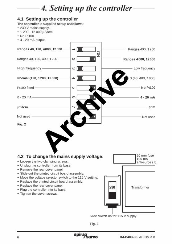
��������������������������4.1 Setting up the controllerThe controller is supplied set up as follows:- 230 V mains supply.- 1 200 - 12 000 �S/cm.- No Pt100.- 4 - 20 mA output.
4.2 To change the mains supply voltage:- Loosen the two clamping screws.- Unplug the controller from its base.- Remove the rear cover panel.- Slide out the printed circuit board assembly.- Move the voltage selector switch to the 115 V setting.- Replace the printed circuit board assembly.- Replace the rear cover panel.- Plug the controller into its base.- Tighten the cover screws.
Fig. 2
Fig. 3
��
�
��
��
��
���
20 mm fuse100 mAanti-surge (T)
Transformer
Slide switch up for 115 V supply
Ranges 40, 120, 4000, 12000 Ranges 400, 1200
Ranges 40, 120, 400, 1200 Ranges 4000, 12000
High frequency
Normal (120, 1200, 12000) x 3 (40, 400, 4000)
Pt100 fitted
0 - 20 mA
µS/cm
Not used Not used
ppm
4 - 20 mA
No Pt100
Low frequency
Archive
IM-P403-35 AB Issue 8 7
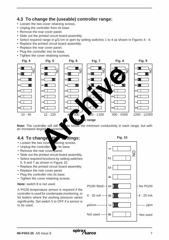
4.3 To change the (useable) controller range:- Loosen the two cover retaining screws.- Unplug the controller from its base.- Remove the rear cover panel.- Slide out the printed circuit board assembly.- Select required range in �S/cm or ppm by setting switches 1 to 4 as shown in Figures 4 - 9.- Replace the printed circuit board assembly.- Replace the rear cover panel.- Plug the controller into its base.- Tighten the cover retaining screws.
4.4 To change other settings:- Loosen the two cover retaining screws.- Unplug the controller from its base.- Remove the rear cover panel.- Slide out the printed circuit board assembly.- Select required functions by setting switches
5, 6 and 7 as shown in Figure 10.- Replace the printed circuit board assembly.- Replace the rear cover panel.- Plug the controller into its base.- Tighten the cover retaining screws.
Note: switch 8 is not used.
A Pt100 temperature sensor is required if thecontroller is used for condensate monitoring, orfor boilers where the working pressure variessignificantly. Set switch 5 to OFF if a sensor isto be used.
��
�
��
��
��
��
�
��
��
��
��
�
��
��
��
��
�
��
��
��
��
�
��
��
��
��
�
��
��
��
��
�
��
��
��
Fig. 4 Fig. 5 Fig. 6 Fig. 7 Fig. 8 Fig. 9
10 - 40 12 - 120 40 - 400 120 - 1200 400 - 4000 1200 - 12000
Fig. 10
Pt100 fitted
0 - 20 mA
�S/cm
Not used
No Pt100
4 - 20 mA
ppm
Not used
Useable range
Note: The controller will still operate below the minimum conductivity in each range, but withan increased degree of uncertainty.
Archive
IM-P403-35 AB Issue 88
�
�
�
�
�
�
�
�
��
��
��
��
�
��
��
��
��
��
��
��
�
��
�
�
�
����
��
�����������������
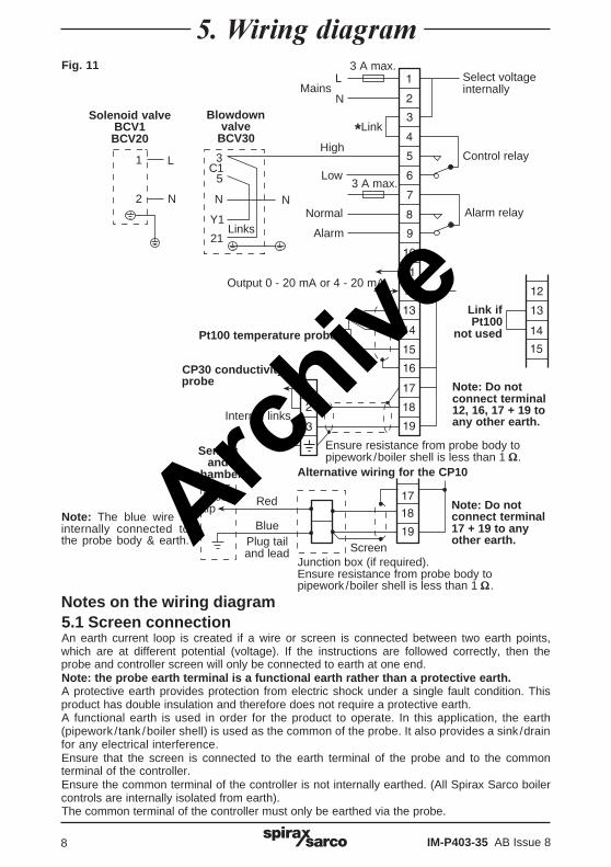
Notes on the wiring diagram5.1 Screen connectionAn earth current loop is created if a wire or screen is connected between two earth points,which are at different potential (voltage). If the instructions are followed correctly, then theprobe and controller screen will only be connected to earth at one end.Note: the probe earth terminal is a functional earth rather than a protective earth.A protective earth provides protection from electric shock under a single fault condition. Thisproduct has double insulation and therefore does not require a protective earth.A functional earth is used in order for the product to operate. In this application, the earth(pipework /tank /boiler shell) is used as the common of the probe. It also provides a sink /drainfor any electrical interference.Ensure that the screen is connected to the earth terminal of the probe and to the commonterminal of the controller.Ensure the common terminal of the controller is not internally earthed. (All Spirax Sarco boilercontrols are internally isolated from earth).The common terminal of the controller must only be earthed via the probe.
Solenoid valveBCV1BCV20
Blowdownvalve
BCV30
Select voltageinternally
Control relay
Alarm relay
Link ifPt100
not used
*Link
L
N
High
Low
Output 0 - 20 mA or 4 - 20 mA
Pt100 temperature probe
Red
Blue
Alternative wiring for the CP10
CP30 conductivityprobe
Internal links
L
N
1
2
3C1
5
N
Y1
21Links
3 A max.
3 A max.
Fig. 11
Mains
Normal
Alarm
N
ScreenJunction box (if required).Ensure resistance from probe body topipework /boiler shell is less than 1 �.
Plug tailand lead
Sensorand
chamber
Probetip
Note: The blue wire isinternally connected tothe probe body & earth.
Note: Do notconnect terminal12, 16, 17 + 19 toany other earth.
Note: Do notconnect terminal17 + 19 to anyother earth.
Ensure resistance from probe body topipework /boiler shell is less than 1 �.
Archive
IM-P403-35 AB Issue 8 9
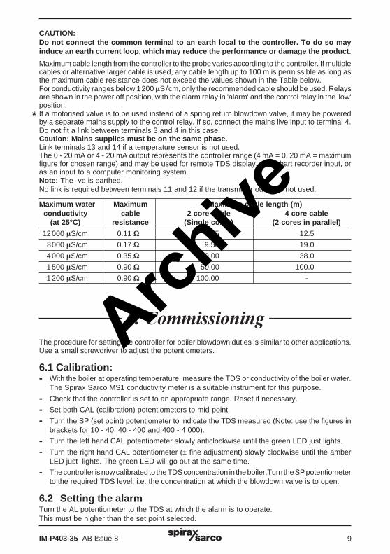
CAUTION:Do not connect the common terminal to an earth local to the controller. To do so mayinduce an earth current loop, which may reduce the performance or damage the product.
Maximum cable length from the controller to the probe varies according to the controller. If multiplecables or alternative larger cable is used, any cable length up to 100 m is permissible as long asthe maximum cable resistance does not exceed the values shown in the Table below.For conductivity ranges below 1200 �S/cm, only the recommended cable should be used. Relaysare shown in the power off position, with the alarm relay in 'alarm' and the control relay in the 'low'position.If a motorised valve is to be used instead of a spring return blowdown valve, it may be poweredby a separate mains supply to the control relay. If so, connect the mains live input to terminal 4.Do not fit a link between terminals 3 and 4 in this case.Caution: Mains supplies must be on the same phase.Link terminals 13 and 14 if a temperature sensor is not used.The 0 - 20 mA or 4 - 20 mA output represents the controller range (4 mA = 0, 20 mA = maximumfigure for chosen range) and may be used for remote TDS display, as a chart recorder input, oras an input to a computer monitoring system.Note: The -ve is earthed.No link is required between terminals 11 and 12 if the transmitter output is not used.
Maximum water Maximum Maximum cable length (m)conductivity cable 2 core cable 4 core cable
(at 25°C) resistance (Single cores) (2 cores in parallel)
12000 �S/cm 0.11 � 6.25 12.5
8000 �S/cm 0.17 � 9.50 19.0
4000 �S/cm 0.35 � 19.00 38.0
1500 �S/cm 0.90 � 50.00 100.0
1200 �S/cm 0.90 � 100.00 -
��������������The procedure for setting the controller for boiler blowdown duties is similar to other applications.Use a small screwdriver to adjust the potentiometers.
6.1 Calibration:- With the boiler at operating temperature, measure the TDS or conductivity of the boiler water.
The Spirax Sarco MS1 conductivity meter is a suitable instrument for this purpose.
- Check that the controller is set to an appropriate range. Reset if necessary.
- Set both CAL (calibration) potentiometers to mid-point.
- Turn the SP (set point) potentiometer to indicate the TDS measured (Note: use the figures inbrackets for 10 - 40, 40 - 400 and 400 - 4 000).
- Turn the left hand CAL potentiometer slowly anticlockwise until the green LED just lights.
- Turn the right hand CAL potentiometer (± fine adjustment) slowly clockwise until the amberLED just lights. The green LED will go out at the same time.
- The controller is now calibrated to the TDS concentration in the boiler.Turn the SP potentiometerto the required TDS level, i.e. the concentration at which the blowdown valve is to open.
6.2 Setting the alarmTurn the AL potentiometer to the TDS at which the alarm is to operate.This must be higher than the set point selected.
*
Archive
IM-P403-35 AB Issue 810
During operation the controller will monitor the TDS and should control the concentration veryclosely by periodically opening the blowdown valve to reduce the TDS. This should result inconsistent TDS readings, typically within ± 10%. Factors reducing the accuracy of controlinclude large variations in boiler pressure (where temperature compensation is not fitted) andwide pH swings. Whenever the TDS is measured by taking a sample of boiler water, the resultshould be compared with the controller set point by turning the SP potentiometer until the LEDschange from green to amber or vice versa.If the boiler is operating normally yet the readings differ significantly, the controller may simplybe recalibrated to the new TDS reading.If it is found that the calibration has drifted to more than twice its original setting, then the probemay need cleaning.
Probe cleaning facilityThe probe cleaning circuit is operated by the spring loaded toggle switch on the front panel:
1. To operate, press and hold down the switch in the 'C' (cleaning) position for one minute.This causes the TDS monitoring function to be suspended, and the probe cleaning circuit tooperate.
2. Release the switch 'C' to return to the normal position.
3. After 15 minutes, the controller output will have stabilised, and it should then be possible torecalibrate the controller near to its original level.
If not, the probe may not be sufficiently clean, so press and hold the switch in the 'C' positionfor one more minute. In most cases the controller can then be recalibrated.
In exceptional circumstances, where abnormal scaling has been allowed to occur in the boiler,it may still not be possible to re-calibrate the controller. In this case, it is permissible to increasethe cleaning period in 5 minute steps up to a maximum of 30 minutes, checking the calibrationafter each step. Wait for 15 minutes after each cycle to allow the system to stabilise.
Important note:The use of the probe cleaning function must not be regarded as a substitute for adequate watertreatment. If scale is forming on the probe tip it is a certain warning that scale will also be formingon the boiler tubes. Boiler water treatment must be investigated.Over-use of the probe cleaning function may shorten the life of the probe.
��!��������
Archive
IM-P403-35 AB Issue 8 11
No special servicing or maintenance of the controller is necessary. The following maintenance,however is recommended for the system.
WeeklyTake a sample of the boiler water through a sample cooler, measure its TDS and check thecontroller calibration with the boiler at normal operating pressure. Check that the blowdownvalve shuts off when the green LED is lit or when the power is removed. Operate any stop valvesto ensure they shut off and remain free.
Every six monthsIsolate the system (or with the boiler empty) and remove the conductivity probe. Clean thetip with fine abrasive paper and the insulation with a bristle brush or cloth. Examine theblowdown control valve / solenoid valve, stop valve and other fittings. Clean and refit orreplace any parts necessary.
Available sparesSpare fuses Stock No. 4033380 Set of 3
"��#����������
Archive
IM-P403-35 AB Issue 812
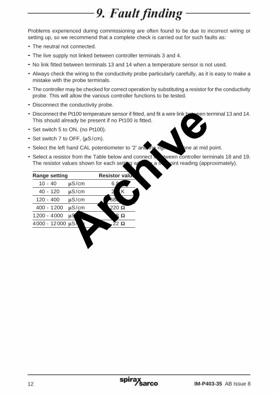
$��%�����������Problems experienced during commissioning are often found to be due to incorrect wiring orsetting up, so we recommend that a complete check is carried out for such faults as:
- The neutral not connected.
- The live supply not linked between controller terminals 3 and 4.
- No link fitted between terminals 13 and 14 when a temperature sensor is not used.
- Always check the wiring to the conductivity probe particularly carefully, as it is easy to make amistake with the probe terminals.
- The controller may be checked for correct operation by substituting a resistor for the conductivityprobe. This will allow the various controller functions to be tested.
- Disconnect the conductivity probe.
- Disconnect the Pt100 temperature sensor if fitted, and fit a wire link between terminal 13 and 14.This should already be present if no Pt100 is fitted.
- Set switch 5 to ON, (no Pt100).
- Set switch 7 to OFF, (�S/cm).
- Select the left hand CAL potentiometer to '2' and the right hand one at mid point.
- Select a resistor from the Table below and connect it between controller terminals 18 and 19.The resistor values shown for each setting will give a midpoint reading (approximately).
Range setting Resistor value
10 - 40 �S/cm 6.8 K
40 - 120 �S/cm 2.2 K
120 - 400 �S/cm 680 �400 - 1200 �S/cm 220 �
1200 - 4000 �S/cm 68 �4000 - 12000 �S/cm 22 �Arch
ive