Embed Size (px)
Citation preview
1
BEDIENUNGSANLEITUNG USER´s MANUAL
ANA-TOOL F810 / F811 / F812 / F820 / F822
AVAILABLE MODELS
ANA-TOOL F810: 4-Channel Balancing Amplifier (available on request) ANA-TOOL F811: 8-Channel Balancing Amplifier ANA-TOOL F812: 4-Channel Balancing Amplifier and 4-Channel Unbalancing Amplifier ANA-TOOL F820: 4-Channel Unbalancing Amplifier (available on request) ANA-TOOL F822: 8-Channel Unbalancing Amplifier
Inhalt / Content Seite / Page Allgemeine Sicherheitshinweise 2 Das Erde / Masse Konzept 3 Anschluss / Steckerbelegung 4 Bedienungsanleitung 5 General Safety Instructions 8 The Earth / Grounding Concept 9 Connection / Connectors 10 User´s Manual 11 Technische Daten / Technical Specifications 14 Anhang / Supplement / Jumper Settings 15 Konformitätserklärung / Conformity Statement 16
development andmanufacturing ofaudio electronic
Turmstrasse 7a78467 KonstanzGERMANY
Tel. +49 (0) 7531 73678Fax +49 (0) 7531 74998www.lake-people.de

2
Allgemeine Sicherheitshinweise
WARNUNG Bitte lesen Sie die folgenden Sicherheitshinweise:
Wasser, Flüssigkeiten, Feuchtigkeit: Das Gerät soll nicht in der Nähe von Wasser- oder Flüssigkeitsquellen benutzt werden. Das Gerät soll nicht in Bereichen grosser Feuchtigkeit betrieben werden. Achten Sie darauf, dass das Gerät nicht in Flüssigkeiten fällt, oder dass Flüssigkeiten durch die Gehäuseöffnungen eindringen können.
Betriebsspannung: Das Gerät darf nur mit den in dieser Bedienungsanleitung angegebenen Quellen betrieben werden.
Erdung: Achten Sie darauf, dass dieses Gerät nur vorschriftsmässig geerdet betrieben wird.
Netzkabel: Achten Sie auf einen einwandfreien Zustand des Netzkabels. Verlegen Sie das Netzkabel so, dass es nicht verletzt werden kann und keine Unfallquelle darstellt. Das Gerät wird mit einem 3-poligen Netzkabel mit deutschem Schuko-Stecker ausgeliefert. Auf Anfrage wird ein 3-poliges nordamerikanisches Netzkabel mitgeliefert. In einigen Ländern muss das Gerät mit einem vom Benutzer beigestellten Netzkabel betrieben werden.
Übersicht: Netzkabelfunktionen und Farben Leiter / CONDUCTOR Farbe COLOR Alternativ Alternativ
L Phase LIVE Braun BROWN Schwarz BLACK N Null NEUTRAL Blau BLUE Weiss WHITE
E Erde EARTH GND Grün-Gelb GREEN+YELLOW Grün GREEN
Netzsicherung: Die Netzsicherung dieses Gerätes ist eingelötet und nur von Innen zugänglich !! Eine durchgebrannte Sicherung weist auf interne Probleme hin und sollte nur im Rahmen von qualifizierten Service- oder Reparaturarbeiten ersetzt werden !!
Umschaltbare Stromversorgung / Mehrbereichs-Stromversorgung Achten Sie auf den im Typenschild angegebenen Bereich der Versorgungsspannung, um einen sicheren Betrieb zu gewährleisten!! Dieses Gerät ist entweder mit einer intern umlötbaren Netzspannung 115 / 230 V AC oder mit einer Mehrbereichsspannung 90 ... 260 V AC ausgerüstet.
Service / Reparatur: Um das Risiko von Feuer und Stromschlag zu reduzieren, soll dieses Gerät vom Benutzer nicht über die in dieser Bedienungsanleitung beschriebenen Arbeiten hinaus gewartet oder repariert werden. Überlassen Sie Service- und Reparaturarbeiten qualifiziertem Personal !!
Elektromagnetische Verträglichkeit: Dieses Gerät entspricht internationalen Spezifikationen, die am Ende dieser Bedienungsanleitung in der KONFORMITÄTSERKLÄRUNG beschrieben sind mit den folgenden Voraussetzungen: - dieses Gerät strahlt keine störenden Emissionen aus - dieses Gerät kann in störenden Umgebungen betrieben werden, auch wenn diese den beabsichtigten Einsatzzweck des Gerätes beeinträchtigen - der Betrieb dieses Gerätes in Umgebungen mit hohen elektromagnetischen Feldern sollte vermieden werden
VOR DEM ÖFFNEN NETZSTECKERZIEHEN!! PULL MAINS BEFOREOPENING!! AVANT D´OUVRIERRETIREZ LA FICHE MALE!!
3
Das Erde / Masse Konzept
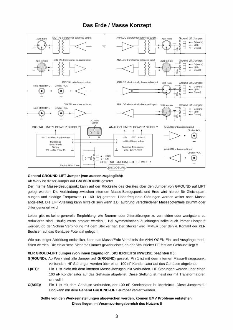
General GROUND-LIFT Jumper (von aussen zugänglich): Ab Werk ist dieser Jumper auf GND/GROUND gesetzt. Der interne Masse-Bezugspunkt kann auf der Rückseite des Gerätes über den Jumper von GROUND auf LIFT gelegt werden. Die Verbindung zwischen internem Masse-Bezugspunkt und Erde wird hierbei für Gleichspan-nungen und niedrige Frequenzen (< 160 Hz) getrennt. Höherfrequente Störungen werden weiter nach Masse abgeleitet. Die LIFT-Stellung kann hilfreich sein wenn z.B. aufgrund verschiedener Massepotentiale Brumm oder Jitter generiert wird.
Leider gibt es keine generelle Empfehlung, wie Brumm- oder Jitterstörungen zu vermeiden oder wenigstens zu reduzieren sind. Häufig muss probiert werden !! Bei symmetrischen Zuleitungen sollte auch immer überprüft werden, ob der Schirm Verbindung mit dem Stecker hat. Der Stecker wird IMMER über den 4. Kontakt der XLR Buchsen auf das Gehäuse-Potential gelegt !!
Wie aus obiger Abbildung ersichtlich, kann das Masse/Erde-Verhältnis der ANALOGEN Ein- und Ausgänge modi-fiziert werden. Die elektrische Sicherheit immer gewährleistet, da der Schutzleiter PE fest am Gehäuse liegt !!
XLR GROUD-LIFT Jumper (von innen zugänglich, SICHERHEITSHINWEISE beachten !! ): G(ROUND): Ab Werk sind alle Jumper auf G(ROUND) gesetzt. Pin 1 ist mit dem internen Masse-Bezugspunkt
verbunden. HF Störungen werden über einen 100 nF Kondensator auf das Gehäuse abgeleitet. L(IFT): Pin 1 ist nicht mit dem internen Masse-Bezugspunkt verbunden. HF Störungen werden über einen
100 nF Kondensator auf das Gehäuse abgeleitet. Diese Stellung ist meist nur mit Transformatoren sinnvoll !!
C(ASE): Pin 1 ist mit dem Gehäuse verbunden, der 100 nF Kondensator ist überbrückt. Diese Jumperstel-lung kann mir dem General GROUND-LIFT Jumper variiert werden.
Sollte von den Werkseinstellungen abgewichen werden, können EMV Probleme entstehen. Diese liegen im Verantwortungsbereich des Nutzers !!
1 2
3
XLR male DIGITAL transformer balanced output
XLR female
1 2
3
DIGITAL transformer balanced input
ANALOG unbalanced outputCinch / RCA
ANALOG unbalanced inputCinch / RCA
DIGITAL unbalanced outputCinch / RCAsolid Metal BNC
DIGITAL unbalanced inputCinch / RCAsolid Metal BNC
12
3
12
3
XLR male Ground Lift Jumper:
Ground Lift Jumper:
ANALOG transformer balanced output
G(round)L(ift)C(ase)
100n
G(round)L(ift)C(ase)
100n
G(round)L(ift)C(ase)
100n
G(round)L(ift)C(ase)
100n
XLR female
12
3
12
3
ANALOG transformer balanced input
XLR male Ground Lift Jumper:ANALOG electronically balanced output
XLR female Ground Lift Jumper:
GND
Earth / PE to Case
Lift
ANALOG electronically balanced input
100n
10k
5V DC stabilized Supply Voltage
stabilized Supply VoltageMultirangeSwitchmode
Supply90 … 260 V AC In
Torroidal Transformer230 / 115 V AC In
DIGITAL UNITS POWER SUPPLY ANALOG UNITS POWER SUPPLY
+18V -18V (others)L
E
N
AC
IN
AC
IN
AC MainsSocket
ENCLOSURE
GENERAL GROUND-LIFT JUMPER
4
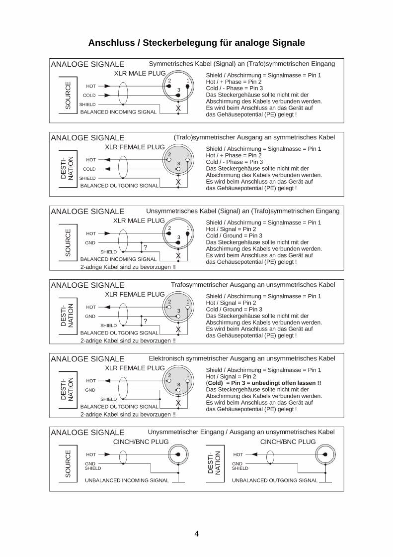
Anschluss / Steckerbelegung für analoge Signale
SO
UR
CE 12
3HOT
COLD
SHIELD X
Symmetrisches Kabel (Signal) an (Trafo)symmetrischen Eingang
BALANCED INCOMING SIGNAL
XLR MALE PLUG Shield / Abschirmung = Signalmasse = Pin 1Hot / + Phase = Pin 2Cold / - Phase = Pin 3Das Steckergehäuse sollte nicht mit der Abschirmung des Kabels verbunden werden.Es wird beim Anschluss an das Gerät auf das Gehäusepotential (PE) gelegt !
ANALOGE SIGNALED
ES
TI-
NAT
ION
12
3HOT
COLD
SHIELD X
(Trafo)symmetrischer Ausgang an symmetrisches Kabel
BALANCED OUTGOING SIGNAL
XLR FEMALE PLUG Shield / Abschirmung = Signalmasse = Pin 1Hot / + Phase = Pin 2Cold / - Phase = Pin 3Das Steckergehäuse sollte nicht mit der Abschirmung des Kabels verbunden werden.Es wird beim Anschluss an das Gerät auf das Gehäusepotential (PE) gelegt !
ANALOGE SIGNALE
SOU
RC
E 12
3HOT
GND
SHIELD X
Unsymmetrisches Kabel (Signal) an (Trafo)symmetrischen Eingang
BALANCED INCOMING SIGNAL
XLR MALE PLUG Shield / Abschirmung = Signalmasse = Pin 1Hot / Signal = Pin 2Cold / Ground = Pin 3Das Steckergehäuse sollte nicht mit der Abschirmung des Kabels verbunden werden.Es wird beim Anschluss an das Gerät auf das Gehäusepotential (PE) gelegt !
ANALOGE SIGNALE
DES
TI-
NAT
ION
12
3HOT
GND
SHIELD X
Trafosymmetrischer Ausgang an unsymmetrisches Kabel
BALANCED OUTGOING SIGNAL
XLR FEMALE PLUG Shield / Abschirmung = Signalmasse = Pin 1Hot / Signal = Pin 2Cold / Ground = Pin 3Das Steckergehäuse sollte nicht mit der Abschirmung des Kabels verbunden werden.Es wird beim Anschluss an das Gerät auf das Gehäusepotential (PE) gelegt !
ANALOGE SIGNALE
?
?
2-adrige Kabel sind zu bevorzugen !!
2-adrige Kabel sind zu bevorzugen !!
SO
UR
CE HOT HOT
GND GNDSHIELD SHIELD
Unysmmetrischer Eingang / Ausgang an unsymmetrisches Kabel
UNBALANCED INCOMING SIGNAL UNBALANCED OUTGOING SIGNAL
CINCH/BNC PLUG CINCH/BNC PLUGANALOGE SIGNALE
DE
STI
-N
ATIO
N
DES
TI-
NAT
ION
12
3HOT
GND
SHIELD X
Elektronisch symmetrischer Ausgang an unsymmetrisches Kabel
BALANCED OUTGOING SIGNAL
XLR FEMALE PLUG Shield / Abschirmung = Signalmasse = Pin 1Hot / Signal = Pin 2(Das Steckergehäuse sollte nicht mit der Abschirmung des Kabels verbunden werden.Es wird beim Anschluss an das Gerät auf das Gehäusepotential (PE) gelegt !
Cold) = Pin 3 = unbedingt offen lassen !!
ANALOGE SIGNALE
2-adrige Kabel sind zu bevorzugen !!

5
ALLGEMEINES ANA-TOOL F8xx in ihren verschiedenen Aus-führungen ist eine achtkanalige Einheit (vier-kanalig auf Anfrage) zum Aufholen, Anpassen, Impedanz ändern, Symmetrieren und Desym-metrieren von allgemeinen Audiosignalquellen. Sie ist das Verbindungsglied zwischen unsym-metrischen Konsumergeräten und symmetri-scher Studio Technik. Zum Anschluss der Konsumergeräte sind die Ein- und Ausgänge als vergoldete Cinch-Buchsen ausgeführt. Die unsymmetrischen rückwärtigen Anschlüsse sind zusätzlich auch auf der Frontplatte vorhanden. Die Ein- und Ausgänge zum Anschluss der Studiotechnik liegen als vergoldete XLR-Buchsen vor. Alle Ausgangspegel können über Spindel-trimmer auf der Front justiert werden. Die symmetrischen Ausgänge sind zum Treiben von 600 Ohm-Lasten ausgelegt. Optional können die symmetrischen Ein- und Ausgänge mit Transformatoren ausgerüstet werden.
DAS GEHÄUSE Das geerdete Gehäuse besteht aus 1 - 2 mm starkem Edelstahl. Dies garantiert eine hohe mechanische Stabilität und Widerstands-fähigkeit gegen rauhe Umwelteinflüsse. Durch die hohe elektrische Leitfähigkeit der unbehandelten Oberflächen ergeben sich her-vorragenden EMV Eigenschaften.
DIE STROMVERSORGUNG Die Stromversorgung erfolgt über eine einge-baute IEC-CEE-Dose. Wenn nötig, kann die Netzspannung intern von 230 V auf 115 V umgestellt werden. Der "POWER"-Schalter befindet sich auf der Frontplatte. Der eingeschaltete Zustand wird durch eine LED unter dem "POWER"-Schalter angezeigt. Ein überdimensionierter Ringkerntrafo erzeugt die internen Betriebsspannungen. Sie sind über lineare Spannungsregler auf +/- 18V stabilisiert um maximale Aussteuerungsreserven zu ge-währleisten.
DIE NETZSICHERUNG Die Sicherung 0,25 AT ist intern auf dem Netz-teil-Print verlötet.
ACHTUNG !! SICHERHEITSHINWEISE BEACHTEN: Eine durchgebrannte Sicherung weist auf inter-ne Probleme hin und sollte nur im Rahmen von qualifizierten Service- oder Reparaturarbeiten ersetzt werden !!
6
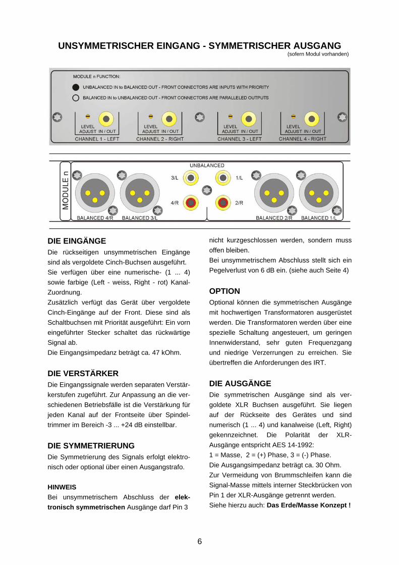
DIE EINGÄNGE Die rückseitigen unsymmetrischen Eingänge sind als vergoldete Cinch-Buchsen ausgeführt. Sie verfügen über eine numerische- (1 ... 4) sowie farbige (Left - weiss, Right - rot) Kanal-Zuordnung. Zusätzlich verfügt das Gerät über vergoldete Cinch-Eingänge auf der Front. Diese sind als Schaltbuchsen mit Priorität ausgeführt: Ein vorn eingeführter Stecker schaltet das rückwärtige Signal ab. Die Eingangsimpedanz beträgt ca. 47 kOhm.
DIE VERSTÄRKER Die Eingangssignale werden separaten Verstär-kerstufen zugeführt. Zur Anpassung an die ver-schiedenen Betriebsfälle ist die Verstärkung für jeden Kanal auf der Frontseite über Spindel-trimmer im Bereich -3 ... +24 dB einstellbar.
DIE SYMMETRIERUNG Die Symmetrierung des Signals erfolgt elektro-nisch oder optional über einen Ausgangstrafo. HINWEIS Bei unsymmetrischem Abschluss der elek-tronisch symmetrischen Ausgänge darf Pin 3
nicht kurzgeschlossen werden, sondern muss offen bleiben. Bei unsymmetrischem Abschluss stellt sich ein Pegelverlust von 6 dB ein. (siehe auch Seite 4)
OPTION Optional können die symmetrischen Ausgänge mit hochwertigen Transformatoren ausgerüstet werden. Die Transformatoren werden über eine spezielle Schaltung angesteuert, um geringen Innenwiderstand, sehr guten Frequenzgang und niedrige Verzerrungen zu erreichen. Sie übertreffen die Anforderungen des IRT.
DIE AUSGÄNGE Die symmetrischen Ausgänge sind als ver-goldete XLR Buchsen ausgeführt. Sie liegen auf der Rückseite des Gerätes und sind numerisch (1 ... 4) und kanalweise (Left, Right) gekennzeichnet. Die Polarität der XLR-Ausgänge entspricht AES 14-1992: 1 = Masse, 2 = (+) Phase, 3 = (-) Phase. Die Ausgangsimpedanz beträgt ca. 30 Ohm. Zur Vermeidung von Brummschleifen kann die Signal-Masse mittels interner Steckbrücken von Pin 1 der XLR-Ausgänge getrennt werden. Siehe hierzu auch: Das Erde/Masse Konzept !
UNSYMMETRISCHER EINGANG - SYMMETRISCHER AUSGANG (sofern Modul vorhanden)
7
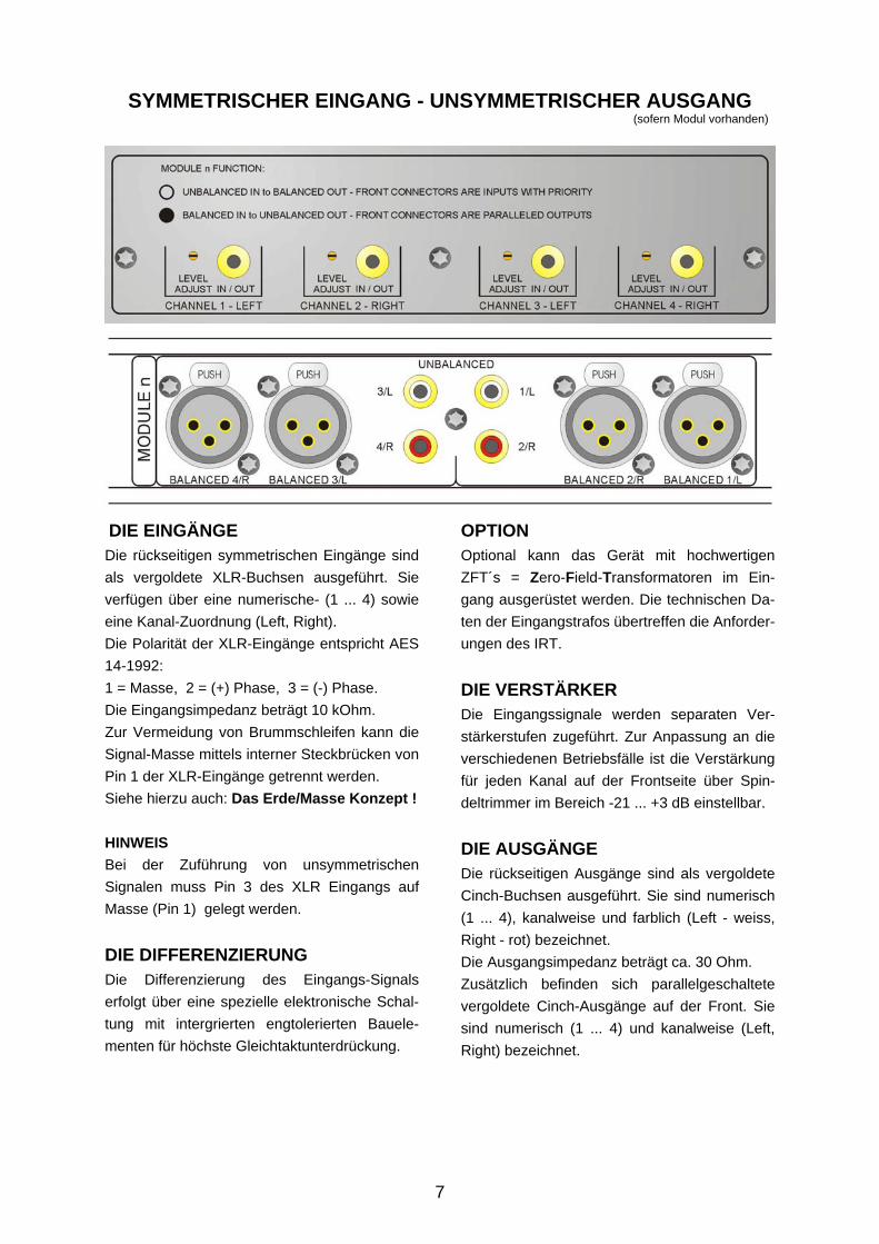
DIE EINGÄNGE Die rückseitigen symmetrischen Eingänge sind als vergoldete XLR-Buchsen ausgeführt. Sie verfügen über eine numerische- (1 ... 4) sowie eine Kanal-Zuordnung (Left, Right). Die Polarität der XLR-Eingänge entspricht AES 14-1992: 1 = Masse, 2 = (+) Phase, 3 = (-) Phase. Die Eingangsimpedanz beträgt 10 kOhm. Zur Vermeidung von Brummschleifen kann die Signal-Masse mittels interner Steckbrücken von Pin 1 der XLR-Eingänge getrennt werden. Siehe hierzu auch: Das Erde/Masse Konzept ! HINWEIS Bei der Zuführung von unsymmetrischen Signalen muss Pin 3 des XLR Eingangs auf Masse (Pin 1) gelegt werden.
DIE DIFFERENZIERUNG Die Differenzierung des Eingangs-Signals erfolgt über eine spezielle elektronische Schal-tung mit intergrierten engtolerierten Bauele-menten für höchste Gleichtaktunterdrückung.
OPTION Optional kann das Gerät mit hochwertigen ZFT´s = Zero-Field-Transformatoren im Ein-gang ausgerüstet werden. Die technischen Da-ten der Eingangstrafos übertreffen die Anforder-ungen des IRT.
DIE VERSTÄRKER Die Eingangssignale werden separaten Ver-stärkerstufen zugeführt. Zur Anpassung an die verschiedenen Betriebsfälle ist die Verstärkung für jeden Kanal auf der Frontseite über Spin-deltrimmer im Bereich -21 ... +3 dB einstellbar.
DIE AUSGÄNGE Die rückseitigen Ausgänge sind als vergoldete Cinch-Buchsen ausgeführt. Sie sind numerisch (1 ... 4), kanalweise und farblich (Left - weiss, Right - rot) bezeichnet. Die Ausgangsimpedanz beträgt ca. 30 Ohm. Zusätzlich befinden sich parallelgeschaltete vergoldete Cinch-Ausgänge auf der Front. Sie sind numerisch (1 ... 4) und kanalweise (Left, Right) bezeichnet.
SYMMETRISCHER EINGANG - UNSYMMETRISCHER AUSGANG (sofern Modul vorhanden)
8
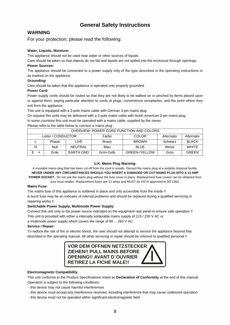
General Safety Instructions WARNING For your protection, please read the following: Water, Liquids, Moisture: This appliance should not be used near water or other sources of liquids. Care should be taken so that objects do not fall and liquids are not spilled into the enclosure through openings. Power Sources: The appliance should be connected to a power supply only of the type described in the operating instructions or as marked on the appliance. Grounding: Care should be taken that this appliance is operated only properly grounded. Power Cord: Power supply cords should be routed so that they are not likely to be walked on or pinched by items placed upon or against them, paying particular attention to cords at plugs, convenience receptacles, and the point where they exit from the appliance. This unit is equipped with a 3-pole mains cable with German 3-pin mains plug. On request this units may be delivered with a 3-pole mains cable with North American 3-pin mains plug. In some countries this unit must be operated with a mains cable, supplied by the owner. Please refer to the table below to connect a mains plug:
OVERVIEW: POWER CORD FUNCTION AND COLORS Leiter / CONDUCTOR Farbe COLOR Alternativ Alternativ
L Phase LIVE Braun BROWN Schwarz BLACK N Null NEUTRAL Blau BLUE Weiss WHITE
E Erde EARTH GND Grün-Gelb GREEN+YELLOW Grün GREEN
U.K. Mains Plug Warning: A moulded mains plug that has been cut off from the cord is unsafe. Discard the mains plug at a suitable disposal facility.
NEVER UNDER ANY CIRCUMSTANCES SHOULD YOU INSERT A DAMAGED OR CUT MAINS PLUG INTO A 13 AMP POWER SOCKET. Do not use the mains plug without the fuse cover in place. Replacement fuse covers can be obtained from
your local retailer. Replacement fuses are 13 amps and MUST be ASTA approved to BS 1362. Mains Fuse: The mains fuse of this appliance is soldered in place and only accessible from the inside !! A burnt fuse may be an indicator of internal problems and should be replaced during a qualified servicing or repairing works !! Switchable Power Supply, Multimode Power Supply: Connect this unit only to the power source indicated on the equipment rear panel to ensure safe operation !! This unit is provided with either a internally solderable mains supply of 115 / 230 V AC or a multimode power supply which covers the range of 90 ... 260 V AC. Service / Repair: To reduce the risk of fire or electric shock, the user should not attempt to service the appliance beyond that described in the operating manual. All other servicing or repair should be referred to qualified personal !!
Electromagnetic Compatibility This unit conforms to the Product Specifications noted as Declaration of Conformity at the end of this manual. Operation is subject to the following conditions: - this device may not cause harmful interferences - this device must accept any interference received, including interference that may cause undesired operation - this device must not be operated within significant electromagnetic field
VOR DEM ÖFFNEN NETZSTECKERZIEHEN!! PULL MAINS BEFOREOPENING!! AVANT D´OUVRIERRETIREZ LA FICHE MALE!!
9
The Earth / Grounding Concept
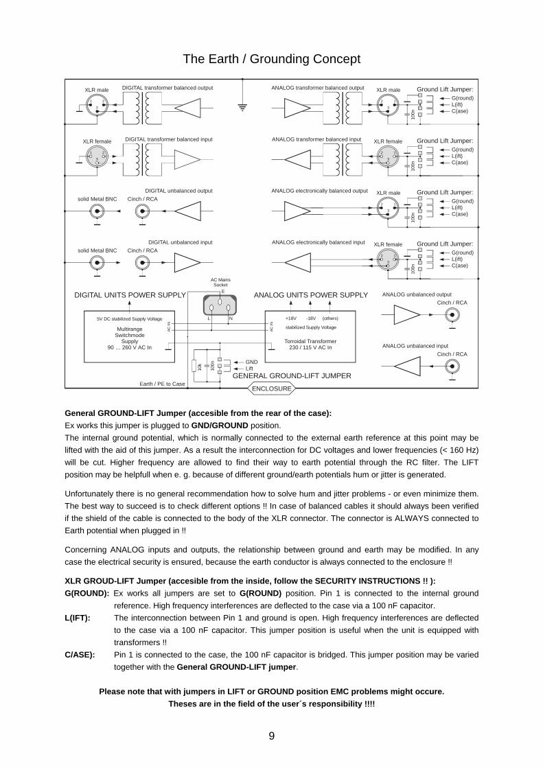
General GROUND-LIFT Jumper (accesible from the rear of the case): Ex works this jumper is plugged to GND/GROUND position. The internal ground potential, which is normally connected to the external earth reference at this point may be lifted with the aid of this jumper. As a result the interconnection for DC voltages and lower frequencies (< 160 Hz) will be cut. Higher frequency are allowed to find their way to earth potential through the RC filter. The LIFT position may be helpfull when e. g. because of different ground/earth potentials hum or jitter is generated.
Unfortunately there is no general recommendation how to solve hum and jitter problems - or even minimize them. The best way to succeed is to check different options !! In case of balanced cables it should always been verified if the shield of the cable is connected to the body of the XLR connector. The connector is ALWAYS connected to Earth potential when plugged in !!
Concerning ANALOG inputs and outputs, the relationship between ground and earth may be modified. In any case the electrical security is ensured, because the earth conductor is always connected to the enclosure !!
XLR GROUD-LIFT Jumper (accesible from the inside, follow the SECURITY INSTRUCTIONS !! ): G(ROUND): Ex works all jumpers are set to G(ROUND) position. Pin 1 is connected to the internal ground
reference. High frequency interferences are deflected to the case via a 100 nF capacitor. L(IFT): The interconnection between Pin 1 and ground is open. High frequency interferences are deflected
to the case via a 100 nF capacitor. This jumper position is useful when the unit is equipped with transformers !!
C/ASE): Pin 1 is connected to the case, the 100 nF capacitor is bridged. This jumper position may be varied together with the General GROUND-LIFT jumper.
Please note that with jumpers in LIFT or GROUND position EMC problems might occure.
Theses are in the field of the user´s responsibility !!!!
1 2
3
XLR male DIGITAL transformer balanced output
XLR female
1 2
3
DIGITAL transformer balanced input
ANALOG unbalanced outputCinch / RCA
ANALOG unbalanced inputCinch / RCA
DIGITAL unbalanced outputCinch / RCAsolid Metal BNC
DIGITAL unbalanced inputCinch / RCAsolid Metal BNC
12
3
12
3
XLR male Ground Lift Jumper:
Ground Lift Jumper:
ANALOG transformer balanced output
G(round)L(ift)C(ase)
100n
G(round)L(ift)C(ase)
100n
G(round)L(ift)C(ase)
100n
G(round)L(ift)C(ase)
100n
XLR female
12
3
12
3
ANALOG transformer balanced input
XLR male Ground Lift Jumper:ANALOG electronically balanced output
XLR female Ground Lift Jumper:
GND
Earth / PE to Case
Lift
ANALOG electronically balanced input
100n
10k
5V DC stabilized Supply Voltage
stabilized Supply VoltageMultirangeSwitchmode
Supply90 … 260 V AC In
Torroidal Transformer230 / 115 V AC In
DIGITAL UNITS POWER SUPPLY ANALOG UNITS POWER SUPPLY
+18V -18V (others)L
E
N
AC IN
AC IN
AC MainsSocket
ENCLOSURE
GENERAL GROUND-LIFT JUMPER
10
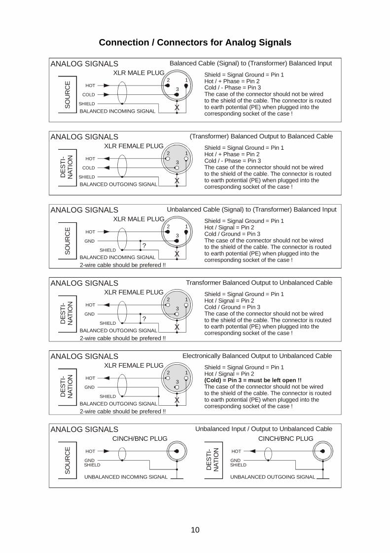
Connection / Connectors for Analog Signals
SO
UR
CE 12
3HOT
COLD
SHIELD X
Balanced Cable (Signal) to (Transformer) Balanced Input
BALANCED INCOMING SIGNAL
XLR MALE PLUG Shield = Signal Ground = Pin 1Hot / + Phase = Pin 2Cold / - Phase = Pin 3The case of the connector should not be wired to the shield of the cable. The connector is routed to earth potential (PE) when plugged into the corresponding socket of the case !
ANALOG SIGNALSD
ES
TI-
NAT
ION
12
3HOT
COLD
SHIELD XBALANCED OUTGOING SIGNAL
XLR FEMALE PLUG(Transformer) Balanced Output to Balanced Cable
Shield = Signal Ground = Pin 1Hot / + Phase = Pin 2Cold / - Phase = Pin 3The case of the connector should not be wired to the shield of the cable. The connector is routed to earth potential (PE) when plugged into the corresponding socket of the case !
ANALOG SIGNALS
SOU
RC
E 12
3HOT
GND
SHIELD X
Unbalanced Cable (Signal) to (Transformer) Balanced Input
BALANCED INCOMING SIGNAL
XLR MALE PLUG Shield = Signal Ground = Pin 1Hot / Signal = Pin 2Cold / Ground = Pin 3The case of the connector should not be wired to the shield of the cable. The connector is routed to earth potential (PE) when plugged into the corresponding socket of the case !
ANALOG SIGNALS
DES
TI-
NAT
ION
12
3HOT
GND
SHIELD XBALANCED OUTGOING SIGNAL
XLR FEMALE PLUGTransformer Balanced Output to Unbalanced Cable
Shield = Signal Ground = Pin 1Hot / Signal = Pin 2Cold / Ground = Pin 3The case of the connector should not be wired to the shield of the cable. The connector is routed to earth potential (PE) when plugged into the corresponding socket of the case !
ANALOG SIGNALS
?
?
2-wire cable should be prefered !!
2-wire cable should be prefered !!
SO
UR
CE HOT HOT
GND GNDSHIELD SHIELD
Unbalanced Input / Output to Unbalanced Cable
UNBALANCED INCOMING SIGNAL UNBALANCED OUTGOING SIGNAL
CINCH/BNC PLUG CINCH/BNC PLUGANALOG SIGNALS
DE
STI
-N
ATIO
N
DES
TI-
NAT
ION
12
3HOT
GND
SHIELD XBALANCED OUTGOING SIGNAL
XLR FEMALE PLUGElectronically Balanced Output to Unbalanced Cable
Shield = Signal Ground = Pin 1Hot / Signal = Pin 2
The case of the connector should not be wired to the shield of the cable. The connector is routed to earth potential (PE) when plugged into the corresponding socket of the case !
(Cold) = Pin 3 = must be left open !!
ANALOG SIGNALS
2-wire cable should be prefered !!
11
GENERAL ANA-TOOL F8xx in its different appearances is a eight-channel unit (four-channel on request) for gain make-up, impedance matching, balan-cing and unbalancing of general audio signal sources. It is the link between unbalanced consumer oriented units and balanced studio equipment. For the connection of consumer technique, gold plated cinch sockets are provided not only on the back panel, but also on the front. Professional studio gear is connected via balanced inputs and outputs. These appear as gold plated XLR typ connectors. All output levels may be conveniently adjusted by front accessible multiturn trimpots The balanced outputs can drive 600 ohm loads. As an option, the balanced inputs and outputs may be equipped with transformers on request.
THE CASE The grounded case is made of 1 -2 mm thick stainless steel. This provides high mechanical stability and resistance against rough handling. The cases surfaces are not treated with any material, so providing excellent electrical con-ductances for optimum EMC characteristics.
THE POWER SUPPLY Mains is connected via a built-in IEC-CEE mains socket. If necessary, mains voltage can be internally altered from 230 to 115 V. The "POWER"-switch is situated on the front panel. Power status is displayed by a LED situated below the power switch. An oversized toroidal transformer delivers the internal supply voltages. They are stabilized by linear voltage regulators to +/- 18 V to guarantee maximum signal headroom.
THE MAINS FUSE The 0,25 AT fuse is internally soldered in place on the power supply PCB.
ATTENTION !! FOLLOW THE SAFETY INSTRUCTIONS: A blown fuse may refer to internal problems and should only been replaced during qualified servicing works !!
12
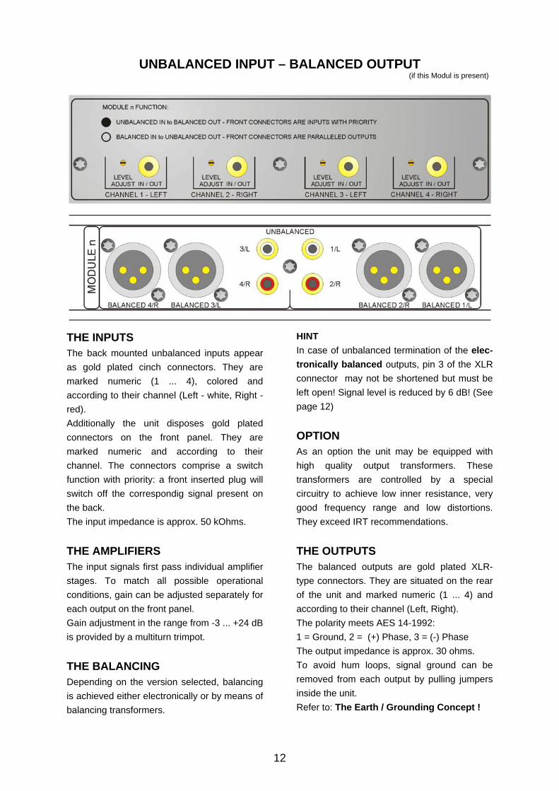
THE INPUTS The back mounted unbalanced inputs appear as gold plated cinch connectors. They are marked numeric (1 ... 4), colored and according to their channel (Left - white, Right - red). Additionally the unit disposes gold plated connectors on the front panel. They are marked numeric and according to their channel. The connectors comprise a switch function with priority: a front inserted plug will switch off the correspondig signal present on the back. The input impedance is approx. 50 kOhms.
THE AMPLIFIERS The input signals first pass individual amplifier stages. To match all possible operational conditions, gain can be adjusted separately for each output on the front panel. Gain adjustment in the range from -3 ... +24 dB is provided by a multiturn trimpot.
THE BALANCING Depending on the version selected, balancing is achieved either electronically or by means of balancing transformers.
HINT In case of unbalanced termination of the elec-tronically balanced outputs, pin 3 of the XLR connector may not be shortened but must be left open! Signal level is reduced by 6 dB! (See page 12)
OPTION As an option the unit may be equipped with high quality output transformers. These transformers are controlled by a special circuitry to achieve low inner resistance, very good frequency range and low distortions. They exceed IRT recommendations.
THE OUTPUTS The balanced outputs are gold plated XLR-type connectors. They are situated on the rear of the unit and marked numeric (1 ... 4) and according to their channel (Left, Right). The polarity meets AES 14-1992: 1 = Ground, 2 = (+) Phase, 3 = (-) Phase The output impedance is approx. 30 ohms. To avoid hum loops, signal ground can be removed from each output by pulling jumpers inside the unit. Refer to: The Earth / Grounding Concept !
UNBALANCED INPUT – BALANCED OUTPUT (if this Modul is present)
13
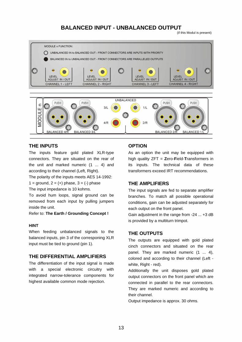
THE INPUTS The inputs feature gold plated XLR-type connectors. They are situated on the rear of the unit and marked numeric (1 ... 4) and according to their channel (Left, Right). The polarity of the inputs meets AES 14-1992: 1 = ground, 2 = (+) phase, 3 = (-) phase The input impedance is 10 kohms. To avoid hum loops, signal ground can be removed from each input by pulling jumpers inside the unit. Refer to: The Earth / Grounding Concept ! HINT When feeding unbalanced signals to the balanced inputs, pin 3 of the corresponing XLR input must be tied to ground (pin 1).
THE DIFFERENTIAL AMPLIFIERS The differentiation of the input signal is made with a special electronic circuitry with integrated narrow-tolerance components for highest available common mode rejection.
OPTION As an option the unit may be equipped with high quality ZFT = Zero-Field-Transformers in its inputs. The technical data of these transformers exceed IRT recommendations.
THE AMPLIFIERS The input signals are fed to separate amplifier branches. To match all possible operational conditions, gain can be adjusted separately for each output on the front panel. Gain adjustment in the range from -24 ... +3 dB is provided by a multiturn trimpot.
THE OUTPUTS The outputs are equipped with gold plated cinch connectors and situated on the rear panel. They are marked numeric (1 ... 4), colored and according to their channel (Left - white, Right - red). Additionally the unit disposes gold plated output connectors on the front panel which are connected in parallel to the rear connectors. They are marked numeric and according to their channel. Output impedance is approx. 30 ohms.
BALANCED INPUT - UNBALANCED OUTPUT (if this Modul is present)
14
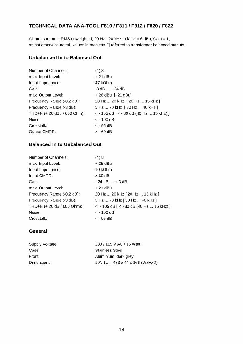
TECHNICAL DATA ANA-TOOL F810 / F811 / F812 / F820 / F822 All measurement RMS unweighted, 20 Hz - 20 kHz, relativ to 6 dBu, Gain = 1, as not otherwise noted, values in brackets [ ] referred to transformer balanced outputs.
Unbalanced In to Balanced Out Number of Channels: (4) 8 max. Input Level: + 21 dBu Input Impedance: 47 kOhm Gain: -3 dB .... +24 dB max. Output Level: + 26 dBu [+21 dBu] Frequency Range (-0.2 dB): 20 Hz ... 20 kHz [ 20 Hz ... 15 kHz ] Frequency Range (-3 dB): 5 Hz ... 70 kHz [ 30 Hz ... 40 kHz ] THD+N (+ 20 dBu / 600 Ohm): < - 105 dB [ < - 80 dB (40 Hz ... 15 kHz) ] Noise: < - 100 dB Crosstalk: < - 95 dB Output CMRR: > - 60 dB
Balanced In to Unbalanced Out Number of Channels: (4) 8 max. Input Level: + 25 dBu Input Impedance: 10 kOhm Input CMRR: > 60 dB Gain: - 24 dB .... + 3 dB max. Output Level: + 21 dBu Frequency Range (-0.2 dB): 20 Hz ... 20 kHz [ 20 Hz ... 15 kHz ] Frequency Range (-3 dB): 5 Hz ... 70 kHz [ 30 Hz ... 40 kHz ] THD+N (+ 20 dB / 600 Ohm): < - 105 dB [ < -80 dB (40 Hz ... 15 kHz) ] Noise: < - 100 dB Crosstalk: < - 95 dB
General Supply Voltage: 230 / 115 V AC / 15 Watt Case: Stainless Steel Front: Aluminium, dark grey Dimensions: 19“, 1U, 483 x 44 x 166 (WxHxD)
15
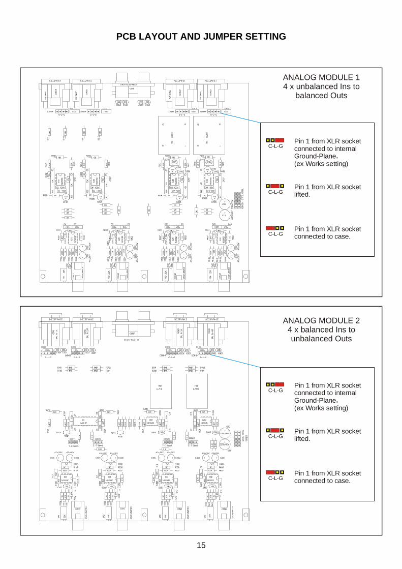
ANALOG MODULE 14 x unbalanced Ins to
balanced Outs
ANALOG MODULE 24 x balanced Ins to unbalanced Outs
C-L-G
C-L-G
C-L-G
Pin 1 from XLR socketconnected to internalGround-Plane.(ex Works setting)
Pin 1 from XLR socketlifted.
Pin 1 from XLR socketconnected to case.
.
C-L-G
C-L-G
C-L-G
Pin 1 from XLR socketconnected to internalGround-Plane.(ex Works setting)
Pin 1 from XLR socketlifted.
Pin 1 from XLR socketconnected to case.
.
PCB LAYOUT AND JUMPER SETTING
16
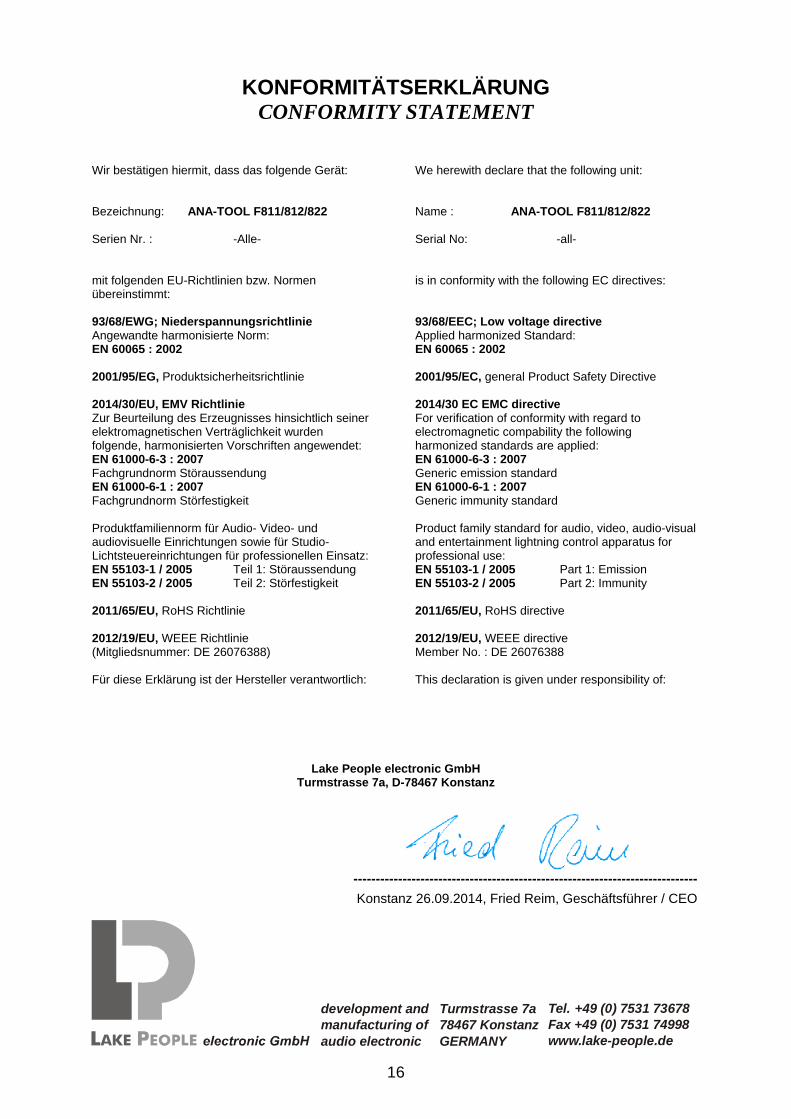
KONFORMITÄTSERKLÄRUNG CONFORMITY STATEMENT
----------------------------------------------------------------------------- Konstanz 26.09.2014, Fried Reim, Geschäftsführer / CEO
Wir bestätigen hiermit, dass das folgende Gerät: Bezeichnung: ANA-TOOL F811/812/822 Serien Nr. : -Alle- mit folgenden EU-Richtlinien bzw. Normen übereinstimmt: 93/68/EWG; Niederspannungsrichtlinie Angewandte harmonisierte Norm: EN 60065 : 2002 2001/95/EG, Produktsicherheitsrichtlinie 2014/30/EU, EMV Richtlinie Zur Beurteilung des Erzeugnisses hinsichtlich seiner elektromagnetischen Verträglichkeit wurden folgende, harmonisierten Vorschriften angewendet: EN 61000-6-3 : 2007 Fachgrundnorm Störaussendung EN 61000-6-1 : 2007 Fachgrundnorm Störfestigkeit Produktfamiliennorm für Audio- Video- und audiovisuelle Einrichtungen sowie für Studio-Lichtsteuereinrichtungen für professionellen Einsatz:EN 55103-1 / 2005 Teil 1: Störaussendung EN 55103-2 / 2005 Teil 2: Störfestigkeit 2011/65/EU, RoHS Richtlinie 2012/19/EU, WEEE Richtlinie (Mitgliedsnummer: DE 26076388) Für diese Erklärung ist der Hersteller verantwortlich:
We herewith declare that the following unit: Name : ANA-TOOL F811/812/822 Serial No: -all- is in conformity with the following EC directives: 93/68/EEC; Low voltage directive Applied harmonized Standard: EN 60065 : 2002 2001/95/EC, general Product Safety Directive 2014/30 EC EMC directive For verification of conformity with regard to electromagnetic compability the following harmonized standards are applied: EN 61000-6-3 : 2007 Generic emission standard EN 61000-6-1 : 2007 Generic immunity standard Product family standard for audio, video, audio-visual and entertainment lightning control apparatus for professional use: EN 55103-1 / 2005 Part 1: Emission EN 55103-2 / 2005 Part 2: Immunity 2011/65/EU, RoHS directive 2012/19/EU, WEEE directive Member No. : DE 26076388 This declaration is given under responsibility of:
Lake People electronic GmbHTurmstrasse 7a, D-78467 Konstanz
development andmanufacturing ofaudio electronic
Turmstrasse 7a78467 KonstanzGERMANY
Tel. +49 (0) 7531 73678Fax +49 (0) 7531 74998www.lake-people.de


![[de] Gebrauchsanleitung 2 [nl] Gebruiksaanwijzing 102 · de Wichtige Sicherheitshinweise 4 Eindringende Feuchtigkeit kann einen Stromschlag verursachen. Nie das Gerät großer Hitze](https://img.pdfslide.tips/doc/110x75/5ba084f309d3f259468cf62c/de-gebrauchsanleitung-2-nl-gebruiksaanwijzing-102-de-wichtige-sicherheitshinweise.jpg)