Embed Size (px)
Citation preview
25022008
C105SControl unit
Kontrolni jednotka
l=4 m
CZ
2
CONTENTS
1. CONTROL UNIT C105S ..............................3 1.2. General ...........................................3 1.2. Technical Information .......................3
2. CONTROL UNIT: USER’S GUIDE ..........................................4 2.1. Selecting presetting times and duration of preset time ......................5 2.2. Presetting times ................................5 2.3. Duration of preset time ......................5
3. INSTRUCTIONS TO ENGINEER FOR MOUNTING THE CONTROL UNIT ................6 3.1. Removing the front ...........................6 3.2. Fixing the device to the wall ...............6 3.3. Mounting the sensor boxes ................7 3.4. Electricial Connections .......................9 230 V 3~, 220 V 3~ .............................13
OBSAH
1. Kontrolni jednotka C105S ..............................3 1.1. Hlavni .....................................3 1.2. Technicke informace .............................3
2. Ridici jednotka Uzivatelska prirucka ......................................4 2.1. Nastaveni casu a doby trvani .............................................5 2.2. Prednastaveni casu ......................................5 2.3. Nastaveni casu ....................................5
3. Navod pro montaz na zed ......................................6 3.1. Vyjmuti predniho krytu .......................6 3.2. Montaz jednotky na zed .......................6 3.3. Montaz cidel ...............7 3.4. Elektricke schema ......................9 230 V 3~, 220 V 3~ .............................13
CZ
3
1.Ridicijednotka C105S
1.1.Hlavni
1.CONTROLUNITC105S
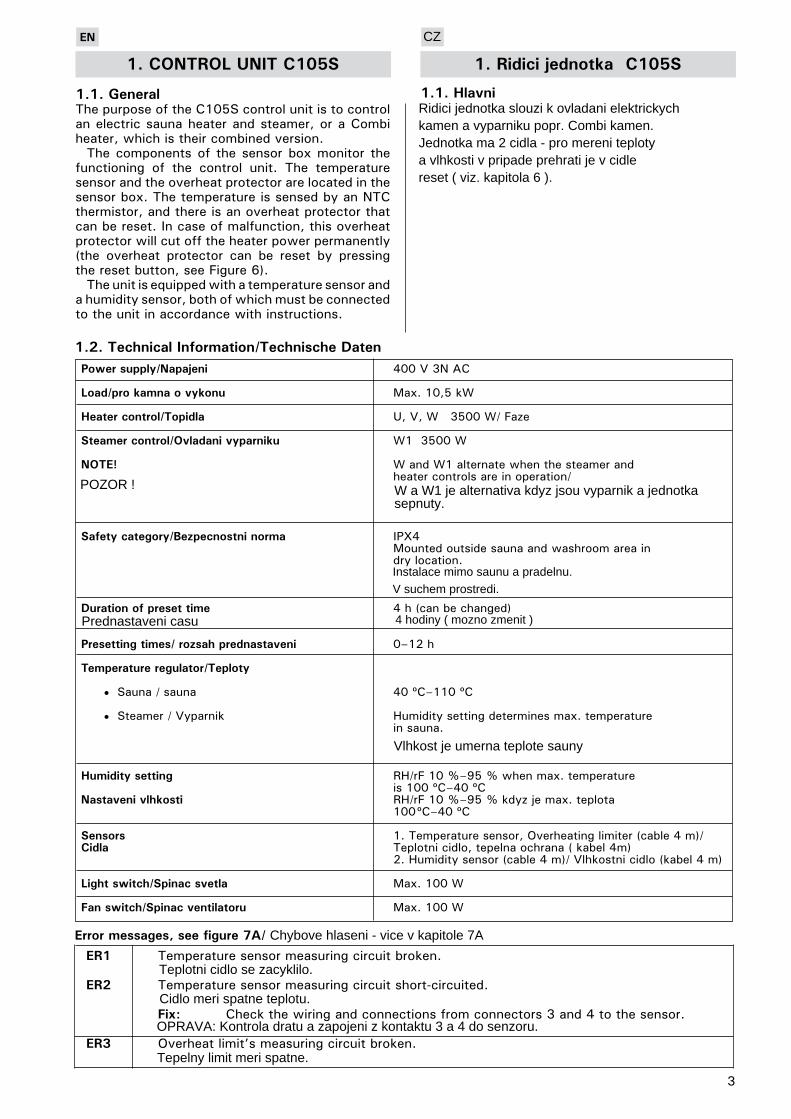
1.1.GeneralThe purpose of the C105S control unit is to control an electric sauna heater and steamer, or a Combi heater, which is their combined version.
The components of the sensor box monitor the functioning of the control unit. The temperature sensor and the overheat protector are located in the sensor box. The temperature is sensed by an NTC thermistor, and there is an overheat protector that can be reset. In case of malfunction, this overheat protector will cut off the heater power permanently (the overheat protector can be reset by pressing the reset button, see Figure 6).
The unit is equipped with a temperature sensor and a humidity sensor, both of which must be connected to the unit in accordance with instructions.
Powersupply/Napajeni 400 V 3N AC
Load/prokamnaovykonu Max. 10,5 kW
Heatercontrol/Topidla U, V, W 3500 W/ Faze
Steamercontrol/Ovladanivyparniku W1 3500 W
NOTE! W and W1 alternate when the steamer and heater controls are in operation/
Safetycategory/Bezpecnostninorma IPX4 Mounted outside sauna and washroom area in dry location.
Durationofpresettime 4 h (can be changed)
Presettingtimes/rozsahprednastaveni 0–12 h
Temperatureregulator/Teploty
• Sauna / sauna 40 ºC–110 ºC • Steamer / Vyparnik Humidity setting determines max. temperature in sauna.
Humiditysetting RH/rF 10 %–95 % when max. temperature is 100 ºC–40 ºC Nastavenivlhkosti RH/rF 10 %–95 % kdyz je max. teplota 100 ºC–40 ºC
Sensors 1. Temperature sensor, Overheating limiter (cable 4 m)/Cidla Teplotni cidlo, tepelna ochrana ( kabel 4m) 2. Humidity sensor (cable 4 m)/ Vlhkostni cidlo (kabel 4 m)
Lightswitch/Spinacsvetla Max. 100 W
Fanswitch/Spinacventilatoru Max. 100 W
1.2.TechnicalInformation/TechnischeDaten
Errormessages,seefigure7A/
ER1 Temperature sensor measuring circuit broken. ER2 Temperature sensor measuring circuit short-circuited. Fix: Check the wiring and connections from connectors 3 and 4 to the sensor. ER3 Overheat limit’s measuring circuit broken.
Ridici jednotka slouzi k ovladani elektrickych kamen a vyparniku popr. Combi kamen. Jednotka ma 2 cidla - pro mereni teploty a vlhkosti v pripade prehrati je v cidle reset ( viz. kapitola 6 ).
POZOR ! W a W1 je alternativa kdyz jsou vyparnik a jednotka sepnuty.
Instalace mimo saunu a pradelnu.V suchem prostredi.
Prednastaveni casu 4 hodiny ( mozno zmenit )
CZ
Vlhkost je umerna teplote sauny
Chybove hlaseni - vice v kapitole 7A
Teplotni cidlo se zacyklilo.
Cidlo meri spatne teplotu.
OPRAVA: Kontrola dratu a zapojeni z kontaktu 3 a 4 do senzoru.
Tepelny limit meri spatne.

Druhým stiskem za vypnou.
Obrazek 1. Kontrolni panel a svetelne kontrolky.
OPRAVA: Kontrola kabelu a zapojeni z kontaktu 5 a 6 do senzoru.
4
2.Navodkpouziti
Figure 1. Control unit connections and indicator lights
1. Hlavni vypinac2. Spinac vyparniku
-
3.
4. Vykon ventilatoru je max. 100 W5. Prikon svetla je max. 100W 6. Displej: Zobrazeni teploty v saune teplota - 13 zablikani Vlhkost 12 zablikani7.
Kontrolka sviti kdyz dosla voda ve vyparniku
8. Kontrolka sviti zelene - vyparnik je zapnuty 9. 10. Kontrolka se rozsviti kdyz je vetrak sepnuty 11. Kontrolka se rozsviti kdyz je svetlo zapnute.
•
•
•
2.INSTRUCTIONSFORUSE
Before you switch the heater on check always that there aren’t any things over the heater or in the near distance of the heater.
1. Master switch2. Steamer’s dual function control switch • knob pushed once: steamer on• knob pushed again: steamer off• knob turned: select desired relative humidity 20 %–95 %. Indicator light 12 flashes whilst adjustment is made.3. Heater’s dual function control switch• knob pushed once: heater on• knob pushed again: heater off• knob turned: select desired sauna bath temperature. Indicator light 13 flashes whilst adjustment is made.4. Fan switch max. 100 W5. Sauna light switch max 100 W6. Screen. Displays sauna temperature (indicator lamp 13 glows) and humidity (indicator lamp 12 glows) alternatively.7. Indicator lamp glows when water in steamer has run out. 8. Indicator light green – steamer on Indicator light flashes – preset time selected9. Indicator light green – heater on Indicator light flashes – preset time selected10. Indicator light glows, when fan is on
Fix: Press the overheat limit reset button. Figure 6. Check the wiring and connections from connectors 1 and 2 to the sensor. Oprava: ER5 Humidity sensor’s temperature measuring circuit open. ER6 Humidity sensor’s temperature measuring circuit short-circuited. Fix: Check the wiring and connections from connectors 5 and 6 to the sensor. Display show all the time only the selected humidity value.
Fix: Check the wiring from connectors 7, 8, 9 and 10 to the humidity sensor.
Stisknuti tlacitka RESET. Viz. kapitola 6.Zkontrolovani kabelu a kontaktu 1 a 2 k senzoru.
Vlhkosti cidlo ukazuje otevreny okruh.
CZ
Vlhkostni cidlo ukazuje kratsi cyklus.
Dispej ukazuje celou dobu jenom vybranou hodnotu vlhkosti.
OPRAVA: Kontrola kabelu a konektoru 7,8,9 a 10 do cidla vlhkosti.
Pred zapnutim kamen zkontrolujte jestli nejsou v blizkosti kamen nejake horlave predmety.
Stiskem se vyparnik zapne.Druhým stiskem za vypne.Otacenim tlacitka se meni vlhkost od 20 do 95 procent.Kontrolka 12krat zablika pote co je nastavena vlhkost.
Spinac kamen
-
•
•
Stiskem se kamna zapnou.
Poté co je nastavena taplota. Kontrolka 13krat zablika.
Kdyz kontrolka blika - lze nastavit prednastaveni sepnutiKontrolka sviti zelene - kamna jsou zapnutyKdyz kontrolka blika - lze nastavit prednastaveni sepnuti
5
12. Kdyz kontrolka sviti, zobrazi se vlhkost 13. Kdyz se kontrolka rozsviti, zobrazi se teplota v saune 14.
2.1.
2.2.Prednastavenicasu
2.3.Dobazprednastavenenhocasu
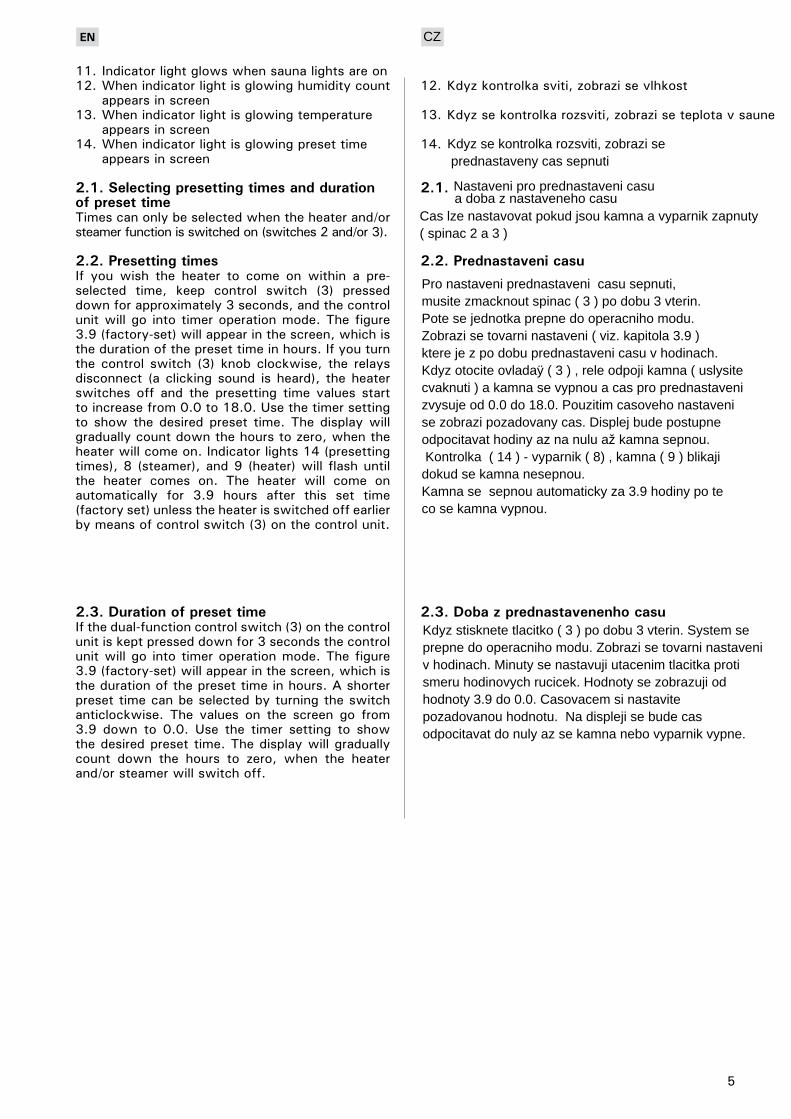
11. Indicator light glows when sauna lights are on12. When indicator light is glowing humidity count appears in screen13. When indicator light is glowing temperature appears in screen14. When indicator light is glowing preset time appears in screen
2.1.SelectingpresettingtimesanddurationofpresettimeTimes can only be selected when the heater and/or steamer function is switched on (switches 2 and/or 3).
2.2.PresettingtimesIf you wish the heater to come on within a pre-selected time, keep control switch (3) pressed down for approximately 3 seconds, and the control unit will go into timer operation mode. The figure 3.9 (factory-set) will appear in the screen, which is the duration of the preset time in hours. If you turn the control switch (3) knob clockwise, the relays disconnect (a clicking sound is heard), the heater switches off and the presetting time values start to increase from 0.0 to 18.0. Use the timer setting to show the desired preset time. The display will gradually count down the hours to zero, when the heater will come on. Indicator lights 14 (presetting times), 8 (steamer), and 9 (heater) will flash until the heater comes on. The heater will come on automatically for 3.9 hours after this set time (factory set) unless the heater is switched off earlier by means of control switch (3) on the control unit.
2.3.DurationofpresettimeIf the dual-function control switch (3) on the control unit is kept pressed down for 3 seconds the control unit will go into timer operation mode. The figure 3.9 (factory-set) will appear in the screen, which is the duration of the preset time in hours. A shorter preset time can be selected by turning the switch anticlockwise. The values on the screen go from 3.9 down to 0.0. Use the timer setting to show the desired preset time. The display will gradually count down the hours to zero, when the heater and/or steamer will switch off.
Kdyz se kontrolka rozsviti, zobrazi se prednastaveny cas sepnuti
CZ
Nastaveni pro prednastaveni casua doba z nastaveneho casu
Cas lze nastavovat pokud jsou kamna a vyparnik zapnuty( spinac 2 a 3 )
Pro nastaveni prednastaveni casu sepnuti,musite zmacknout spinac ( 3 ) po dobu 3 vterin.Pote se jednotka prepne do operacniho modu.Zobrazi se tovarni nastaveni ( viz. kapitola 3.9 )ktere je z po dobu prednastaveni casu v hodinach.Kdyz otocite ovladaÿ ( 3 ) , rele odpoji kamna ( uslysite cvaknuti ) a kamna se vypnou a cas pro prednastaveni zvysuje od 0.0 do 18.0. Pouzitim casoveho nastaveni se zobrazi pozadovany cas. Displej bude postupneodpocitavat hodiny az na nulu až kamna sepnou. Kontrolka ( 14 ) - vyparnik ( 8) , kamna ( 9 ) blikajidokud se kamna nesepnou. Kamna se sepnou automaticky za 3.9 hodiny po te co se kamna vypnou.
Kdyz stisknete tlacitko ( 3 ) po dobu 3 vterin. System se prepne do operacniho modu. Zobrazi se tovarni nastaveni v hodinach. Minuty se nastavuji utacenim tlacitka proti smeru hodinovych rucicek. Hodnoty se zobrazuji od hodnoty 3.9 do 0.0. Casovacem si nastavitepozadovanou hodnotu. Na displeji se bude cas odpocitavat do nuly az se kamna nebo vyparnik vypne.
6
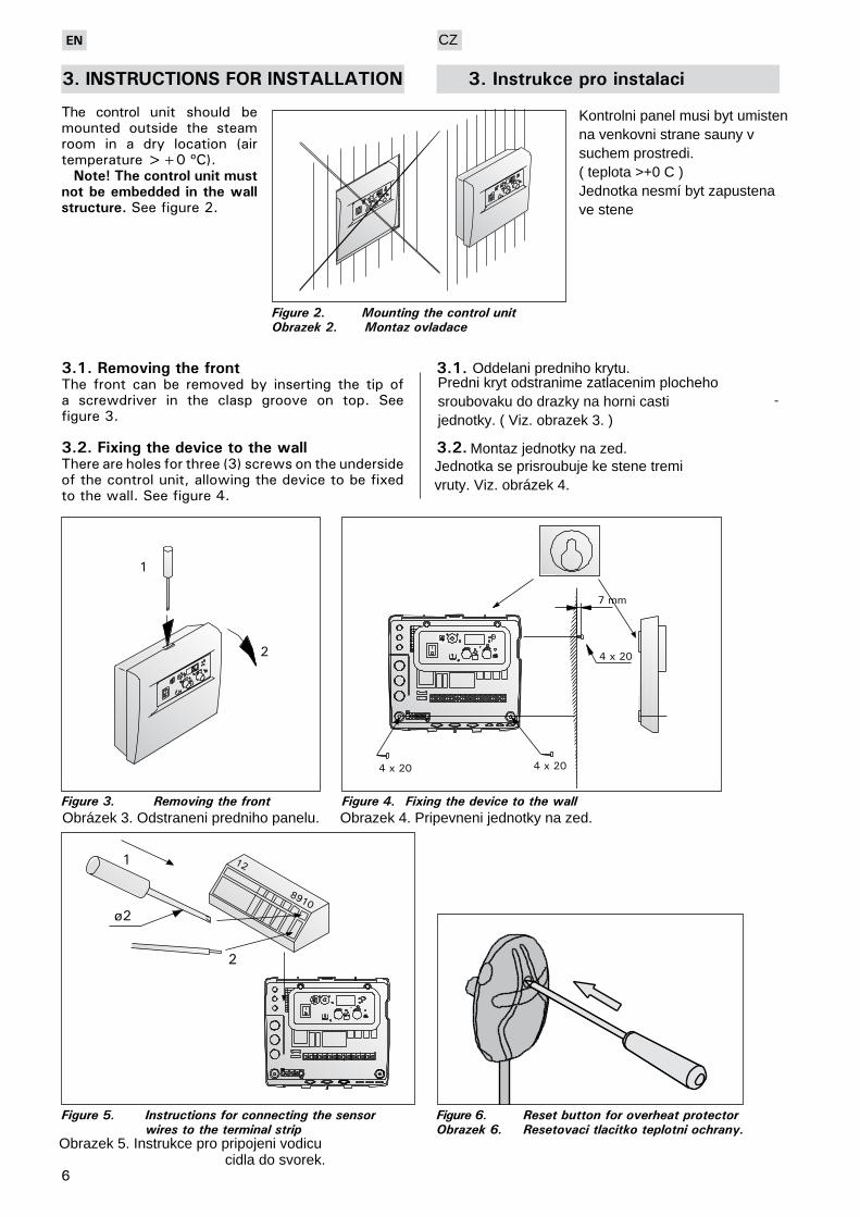
Figure 5. Instructions for connecting the sensor wires to the terminal strip
Figure 4. Fixing the device to the wall
Figure 3. Removing the front
3.1.RemovingthefrontThe front can be removed by inserting the tip of a screwdriver in the clasp groove on top. See figure 3.
3.2.FixingthedevicetothewallThere are holes for three (3) screws on the underside of the control unit, allowing the device to be fixed to the wall. See figure 4.
3.1.
-
3.2.
Figure 6. Reset button for overheat protectorObrazek 6. Resetovaci tlacitko teplotni ochrany.
1
!
2
Figure 2. Mounting the control unitObrazek 2. Montaz ovladace
!
!
3.INSTRUCTIONSFORINSTALLATION
The control unit should be mounted outside the steam room in a dry location (air temperature >+0 ºC).
Note!Thecontrolunitmustnotbeembeddedinthewallstructure. See figure 2.
3.Instrukceproinstalaci
Kontrolni panel musi byt umisten na venkovni strane sauny v suchem prostredi.( teplota >+0 C )Jednotka nesmí byt zapustenave stene
Oddelani predniho krytu.
Montaz jednotky na zed.
Predni kryt odstranime zatlacenim plocheho sroubovaku do drazky na horni casti jednotky. ( Viz. obrazek 3. )
Jednotka se prisroubuje ke stene tremi vruty. Viz. obrázek 4.
Obrázek 3. Odstraneni predniho panelu. Obrazek 4. Pripevneni jednotky na zed.
Obrazek 5. Instrukce pro pripojeni vodicucidla do svorek.
CZ

7
Figure 7A. The location of the C105S control unit temperature and humidity sensor boxes when used with wall-mounted heaters.
Obrazek 7A. Spravne umisteni cidel na zed
3.3.MountingthesensorboxesTo control wall-mounted Combi heaters and heaters and steamers as separate units (Harvia SS20) in the sauna by means of the control unit a temperature sensor, connected to the unit, must be mounted on the sauna wall above the heater in line with the midpoint of the heater’s breadth and 100 mm below the ceiling.
The humidity sensor must be mounted on the sauna wall as far away as possible from the heater and 500–700 mm below the ceiling.
When the C105S control unit is being used to control a Combi heater standing on the floor or
3.3.Montazcidel
CZ
Kontrolni jednotka C105S Resetovaci tlactiko pro tepelnou ochranu ( obr. 6 )
Cidlo teploty.
Cidlo vlhkosti.
Pokud chcete, aby jednotka spravne pracovala musi byt cidla umisteny spravne dle obrazku.Teplotni cidlo 10 cm pod strop.Vlhkostni cidlo od stropu 50 - 70 cm.Viz. obrazek
8
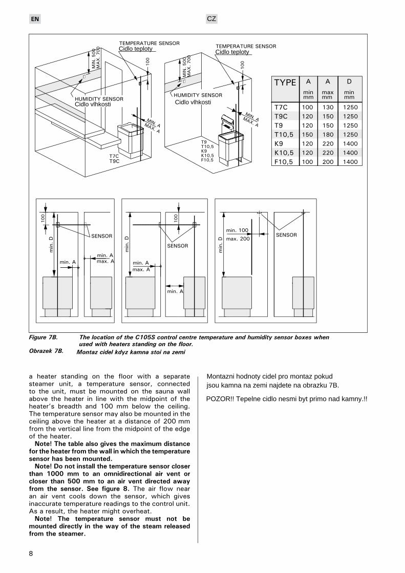
a heater standing on the floor with a separate steamer unit, a temperature sensor, connected to the unit, must be mounted on the sauna wall above the heater in line with the midpoint of the heater’s breadth and 100 mm below the ceiling. The temperature sensor may also be mounted in the ceiling above the heater at a distance of 200 mm from the vertical line from the midpoint of the edge of the heater.
Note!Thetablealsogivesthemaximumdistancefortheheaterfromthewallinwhichthetemperaturesensorhasbeenmounted.
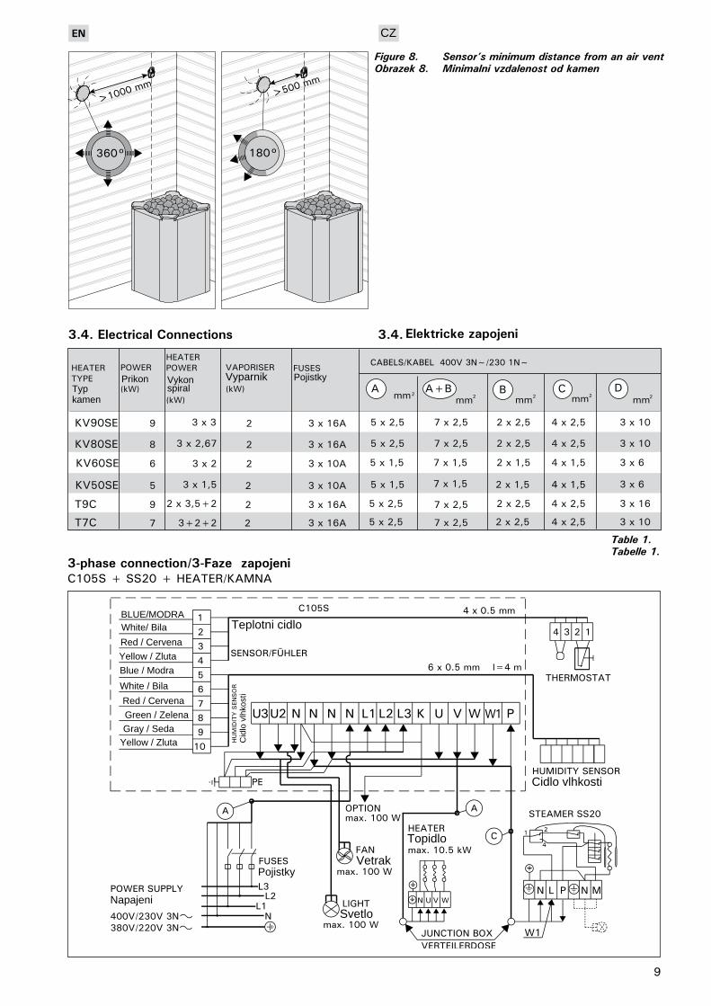
Note!Donotinstallthetemperaturesensorcloserthan 1000 mm to an omnidirectional air vent orcloserthan500mmtoanairventdirectedawayfrom the sensor. See figure 8. The air flow near an air vent cools down the sensor, which gives inaccurate temperature readings to the control unit. As a result, the heater might overheat.
Note! The temperature sensor must not bemounteddirectlyinthewayofthesteamreleasedfromthesteamer.
Figure 7B. The location of the C105S control centre temperature and humidity sensor boxes when used with heaters standing on the floor.Obrazek 7B. Montaz cidel kdyz kamna stoji na zemi
Cidlo teplotyCidlo teploty
CZ
Cidlo vlhkostiCidlo vlhkosti
Montazni hodnoty cidel pro montaz pokudjsou kamna na zemi najdete na obrazku 7B.
POZOR!! Tepelne cidlo nesmi byt primo nad kamny.!!
9
Table 1.Tabelle 1.
C105S + SS20 + HEATER/KAMNA3-phaseconnection/3-Faze zapojeni
360° 180°
>1000 mm>500 mm
Figure 8. Sensor’s minimum distance from an air ventObrazek 8. Minimalni vzdalenost od kamen
3.4.ElectricalConnections 3.4. Elektrickezapojeni
Typ kamen
Prikon
CZ
Vykonspiral
Vyparnik Pojistky
BLUE/MODRAWhite/ Bila
Red / Cervena
Yellow / Zluta
Blue / Modra
White / Bila
Red / Cervena
Green / Zelena
Gray / SedaYellow / Zluta
Teplotni cidlo
Cid
lo v
lhko
sti
Cidlo vlhkosti
Pojistky
NapajeniSvetlo
Vetrak
Topidlo

10
C105S+KV50SEA-KV90SEA (T7CA-T9CA)
C105S+KV50SE-KV90SE, T7C-T9C
Automaticfilling/ Automatickevypousteni
BLUE/MODRAWhite/ Bila
Red / Cervena
Yellow / Zluta
Blue / Modra
White / Bila
Red / Cervena
Green / Zelena
Gray / Seda
Yellow / Zluta
BLUE/MODRAWhite/ Bila
Red / Cervena
Yellow / Zluta
Blue / Modra
White / Bila
Red / Cervena
Green / Zelena
Gray / Seda
Yellow / Zluta
Teplotni cidlo
Teplotni cidlo
Cid
lo v
lhko
sti
Cidlo vlhkosti
Pojistky
Napajeni Svetlo
Vetrak
Topidlo
Cid
lo v
lhko
sti
Cidlo vlhkosti
Pojistky
Napajeni Svetlo
Vetrak
Topidlo

11
*) Heaters’ connections must be changed when using single phase connection. Die Anschlüsse des Saunaofens müssen geändert werden, wenn ein einphasiger Anschluss erfolgt.
C105S+SS20+HEATER/SAUNAOFEN
C105S+KV50SE-KV90SE, T7C-T9C
1-phaseconnection/1-PhaseAnschluss
Cid
lo v
lhko
sti
Cidlo vlhkosti
PojistkyNapajeni
Svetlo
VetrakTopidlo
BLUE/MODRA
White/ Bila
Red / Cervena
Yellow / Zluta
Blue / Modra
White / Bila
Red / Cervena
Green / Zelena
Gray / Seda
Yellow / Zluta
BLUE/MODRAWhite/ Bila
Red / Cervena
Yellow / Zluta
Blue / Modra
White / Bila
Red / Cervena
Green / Zelena
Gray / Seda
Yellow / Zluta
Cidlo vlhkosti
Cid
lo v
lhko
sti
PojistkyNapajeni
Svetlo
Vetrak
Topidlo
CZ
Cidlo vlhkosti
12
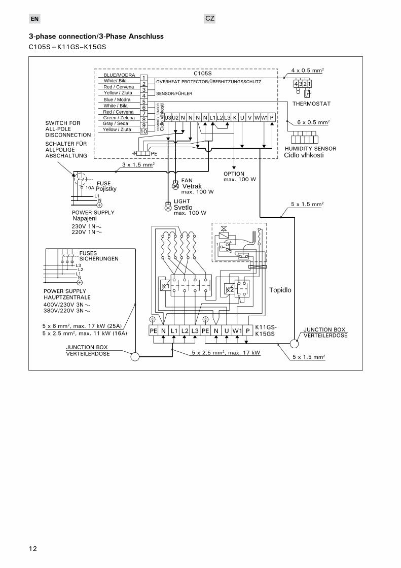
C105S+K11GS–K15GS
3-phaseconnection/3-PhaseAnschluss
Cid
lo v
lhko
sti
Pojistky
Napajeni
Svetlo
Vetrak
Topidlo
CZ
BLUE/MODRAWhite/ BilaRed / CervenaYellow / Zluta
Blue / ModraWhite / BilaRed / CervenaGreen / ZelenaGray / SedaYellow / Zluta
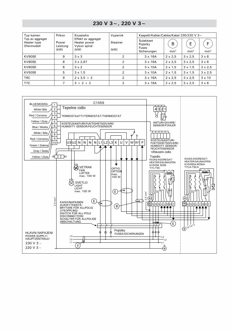
230V3~,220V3~
Typ kamenTyp av aggregatHeater typeOfenmodell
Prikon
PowerLeistung(kW)
KiuastehoEffekt av aggregatHeater powerVykon spiral(kW)
Vyparnik
Steamer
(kW)
Kaapelit/Kablar/Cables/Kabel 230/220 V 3~
SulakkeetPojistkyFusesSicherungen
B
mm2
E
mm2
F
mm2
KV90SE 9 3 x 3 2 3 x 16A 2 x 2,5 3 x 2,5 3 x 6
KV80SE 8 3 x 2,67 2 3 x 16A 2 x 2,5 3 x 2,5 3 x 6
KV60SE 6 3 x 2 2 3 x 10A 2 x 1,5 3 x 1,5 3 x 2,5
KV50SE 5 3 x 1,5 2 3 x 10A 2 x 1,5 3 x 1,5 3 x 2,5
T9C 9 2 x 3,5 + 2 2 3 x 16A 2 x 2,5 3 x 2,5 3 x 10
T7C 7 3 + 2 + 2 2 3 x 16A 2 x 2,5 3 x 2,5 3 x 6
BLUE/MODRA
White/ Bila
Red / Cervena
Yellow / Zluta
Blue / Modra
White / Bila
Red / Cervena
Green / Zelena
Gray / Seda
Yellow / Zluta
SVETLO
VETRAK
HLAVNI NAPAJENI
Vlhkostni cidlo
Pojistky
Topidlo
Tepelne cidlo
Harvia OyPL 12
40951 MuurameFinland
www.harvia.fi


![speciale XIV premio di poesia “Pietro Casu”aprile 2019 a. XXV, n. speciale [149] speciale XIV premio di poesia “Pietro Casu” Ammentu Fabrizio… “L’ultimo concerto”](https://img.pdfslide.tips/doc/110x75/5f8ac193cb1a48727128c615/speciale-xiv-premio-di-poesia-aoepietro-casua-aprile-2019-a-xxv-n-speciale.jpg)