Embed Size (px)
Citation preview
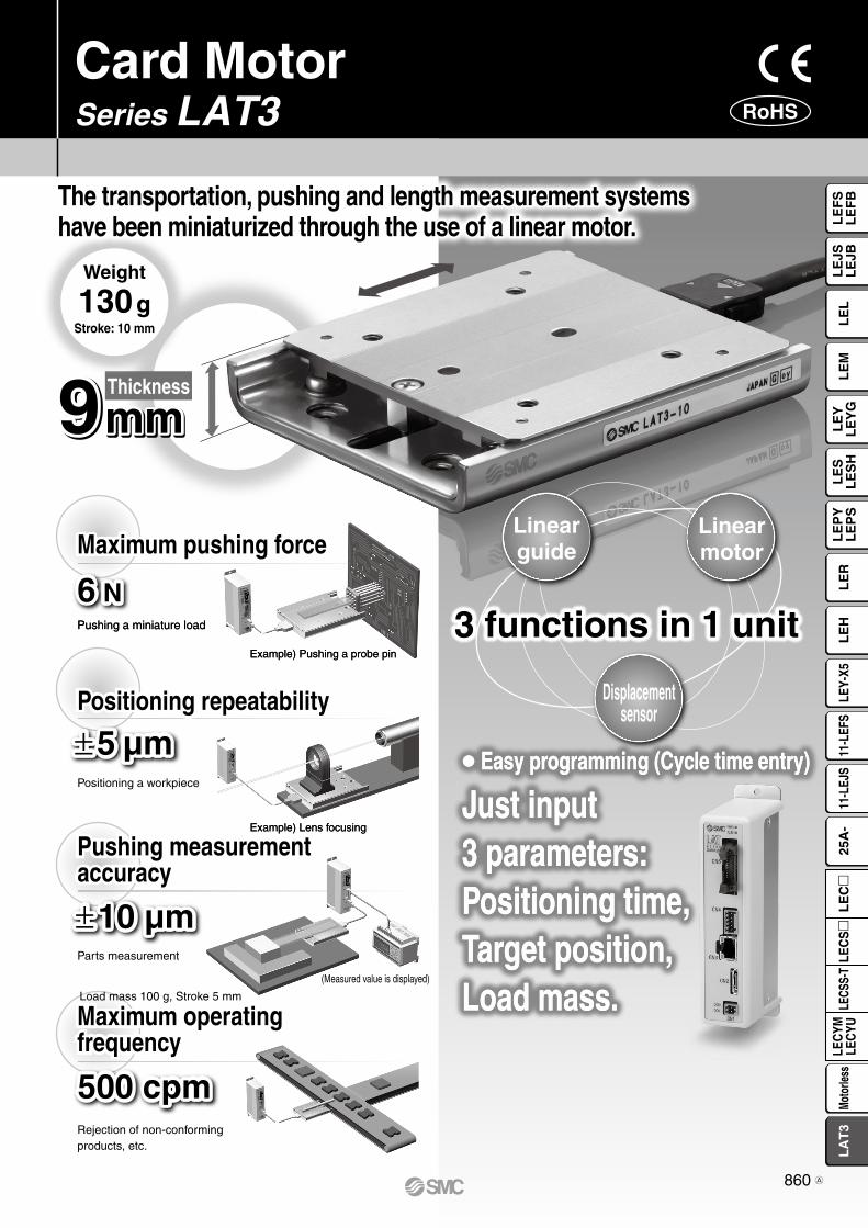
9mm9mm9mmThickness
Pushing a miniature loadPushing a miniature load
Rejection of non-conforming products, etc.Rejection of non-conforming products, etc.
Parts measurement
(Measured value is displayed)
Maximum pushing force
6 N6 N
Pushing measurement accuracy
±10 µm±10 µm
500 cpm500 cpm
Load mass 100 g, Stroke 5 mm
Maximum operating frequency
Positioning a workpiecePositioning a workpiece
Positioning repeatability
±5 µm±5 µm
Example) Lens focusing Example) Lens focusing
Example) Pushing a probe pin Example) Pushing a probe pin
Easy programming (Cycle time entry)
Just input 3 parameters: Positioning time, Target position, Load mass.
Easy programming (Cycle time entry)
Just input 3 parameters: Positioning time, Target position, Load mass.
3 functions in 1 unit
Linearmotor
Linearguide
Displacementsensor
Weight
130 gStroke: 10 mm
The transportation, pushing and length measurement systems have been miniaturized through the use of a linear motor.
Card MotorSeries LAT3 RoHS
860
LE
FS
LE
FB
LE
LL
EJS
LE
JBL
EM
LE
YL
EY
GL
ES
LE
SH
LE
PY
LE
PS
LE
RL
EH
LEY-
X511
-LEF
S11
-LEJ
S25
A-
LEC
YMLE
CYU
LECS
S-T
LA
T3
Moto
rless
LEC
S
LE
C
A

Model
LAT3-10LAT3-20LAT3-30
W (mm)
50
L (mm)
60
90
120
H (mm)
9
Weight (g)
130
190
250
Model StrokeSensor
(Optical linear encoder)
Resolution
Linear motor
Type
Linear guide PushingPositioningrepeatability
Type Maximuminstantaneous thrust Accuracy
Pushingmeasurement
Maximum load mass Maximumspeed
Accuracy Horizontal
LAT3F
LAT3
Compact and lightweight
Series Variations
Card Motor
2 body mounting options
Bottom mounting (Tapped holes)
Top mounting (Through hole)
Linear guide
Table
The cable connector does not protrude above the actuator.
W
H
L
Linear encoder scale
(Moving side)
Linear encoder sensor head
(Fixed side)
Rail
Permanentmagnet
Coil
The permanent magnet is mounted on the bottom side of the table, and the coil is mounted on the top surface of the rail. When current is supplied to the coil, a north pole (N) is generated in the middle of the top surface of the coil. This north pole attracts the south pole (S) of the permanent magnet on the left and repels the north pole on the right, and these attracting and re-pelling forces generate the thrust force. Therefore, thrust force is ap-plied to the table in the right direction, and the table moves to the right.When current is applied to the coil in the reverse direction, a south pole will be generated in the middle of the top surface of the coil. Similarly, a thrust force will be applied to the table in the left direction, and the table moves to the left.
Moves in the left direction
NS
S
Force
Moves in the right direction
NS
N
Force
CoilRail
Permanent magnet
Table
102030
1.25 µm Moving magnetictype linear motor
Linear guide withcirculating balls
500 g
Vertical
100 g
50 g
400 mm/s±5 µm
±90 µm
±10 µm
±100 µm30 µm
The table is provided with dowel pin holes for locating the workpiece as standard equipment.
Dowel pin holesfor locatingthe actuator body
Four tapped holesfor mountingthe actuator body
Structure and Working Principle
Cable Mounting
Workpiece Mounting Body Mounting
Two dowel pin holesfor locating the workpieceWorkpiece mounting
(Tapped holes)
Dowel pin holes for locating the workpiece
Four tapped holesfor mountingthe workpiece
Two dowel pin holes for locating the actuator body
Stopper (to prevent the tablefrom separating from the actuator)
Actuator cable
Card Motor
Table Connector
5.2 N6 N
5.5 N
861

Speed entry methodCycle time entry methodS
peed
Positioning time
Speed entry methodCycle time entry method
Spe
ed
Positioning time
Current positionTarget position
Pushing
Low speed
Target position
The functions described below makes the start-up quick and easy.
CN5CN3
PCController
Parallel input/output signals
Absolute:The table moves to the target position with reference to the origin position and stops there. Relative :The table moves to the target position with reference to the current position and stops there.
Positioning operation (Absolute • Relative)
Pushing operation (Absolute • Relative)Selection of
operation typeOperating condition
Step data
Start-up time is reduced greatly with a systemthat is ready-to-use and easy to set up.
Function for measuring and differentiation of workpieces
Parallel input/output status check function
Built-in operation patterns Cycle time entry method
Step data input
The size of the workpiece can be measured basedon the table stopping position by driving the tableuntil it comes into contact with the workpiece.The workpieces can be differentiated or checked for quality using parallel output signals that correspond topreset table position ranges.Furthermore, using the multi-counter (optional accessory: refer to page 895) makes it possible to display the tableposition and output up to 31 preset points.
A
AB
B
PLC
PLC
Series LAT3
The status of the parallel input signals can be checked, or the parallel output signals can be activated manually using a PC.
Only target position and positioning time need to be entered, so there is no need to enter the speed, acceleration and decel-eration.(Using the speed entry method allows you to enter the speed, acceleration and deceleration.)
The Card Motor operation type and condition are preset in the step data. The Card Motor is operated according to the con-tents of the selected preset step data number.
The table moves to a position close to the target posi-tion, decelerates to low speed and starts pushing after the table has come in contact with the workpiece.
862
LE
FS
LE
FB
LE
LL
EJS
LE
JBL
EM
LE
YL
EY
GL
ES
LE
SH
LE
PY
LE
PS
LE
RL
EH
LEY-
X511
-LEF
S11
-LEJ
S25
A-
LEC
YMLE
CYU
LECS
S-T
LA
T3
Moto
rless
LEC
S
LE
C

Card Motor
Examples of positioning applications
Examples of measurement applications
The applications described below are just a few examples.When using the Card Motor, select an appropriate model by carefully checking the specifications.
Application Examples of Card Motor
Sensor head movement and positioning Component movement and positioning
Component supply to tape Workpiece alignment
Measurement of glass substrate thickness (multiple points)
Measurement of tape thickness
Electronic component pick and place
Component separation (escapement)
Measurement of workpiece height
Measurement of cable outside diameter
863

Alignment of components on pallet by vibration Distribution of workpieces
Pushing of workpieces (soft touch) Positioning of workpieces Cutting of resin mold component runners
Tape alignment Switch inspection High-density layout
Series LAT3
Examples of high frequency actuation
Examples of pushing applications
864
LE
FS
LE
FB
LE
LL
EJS
LE
JBL
EM
LE
YL
EY
GL
ES
LE
SH
LE
PY
LE
PS
LE
RL
EH
LEY-
X511
-LEF
S11
-LEJ
S25
A-
LEC
YMLE
CYU
LECS
S-T
LA
T3
Moto
rless
LEC
S
LE
C
L3
L2
+ A
2
A1 + L1
0.0100
200
300
400
500
600
0
(Horizontal)
15 30 45 60 75 90
(Vertical)Mounting angle θ [°]
Allo
wab
le lo
ad m
ass
Wm
ax [g
]
0
50
100
150
200
250
300
0 5 10 15 20 25 30
Stroke(Positioning distance) St [mm]
Sho
rtes
t pos
ition
ing
time
Tm
in [m
s] W = 200
130
An
M = W/1000 · 9.8 (Ln + An)/1000
Mmax
α = M/Mmax
Σαp + αy + αr 1
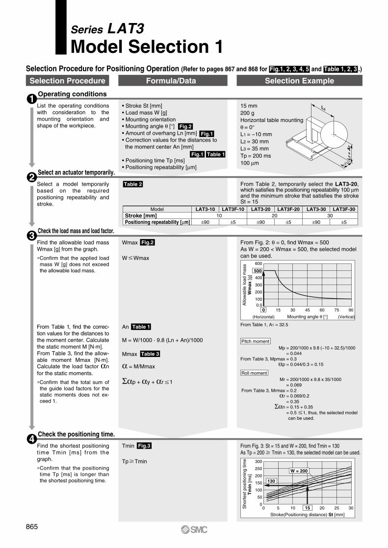
• Stroke St [mm]• Load mass W [g]• Mounting orientation• Mounting angle θ [°]• Amount of overhang Ln [mm]• Correction values for the distances to the moment center An [mm]
• Positioning time Tp [ms]• Positioning repeatability [μm]
Fig.2
Fig.2
Fig.3
Fig.1
Fig.1 Table 1
Table 2
Table 1
Table 3
Selection Procedure for Positioning Operation (Refer to pages 867 and 868 for Fig.1, 2, 3, 4, 5 and Table 1, 2, 3 .)
Operating conditions1
15 mm200 gHorizontal table mountingθ = 0°L1 = −10 mmL2 = 30 mmL3 = 35 mmTp = 200 ms100 μm
List the operating conditions with consideration to the mounting orientation and shape of the workpiece.
Select an actuator temporarily.2
Select a model temporarily based on the required positioning repeatability and stroke.
From Table 2, temporarily select the LAT3-20, which satisfies the positioning repeatability 100 μm and the minimum stroke that satisfies the stroke St = 15
Check the positioning time.4
Tmin
Tp Tmin
Mp = 200/1000 x 9.8 (−10 + 32.5)/1000 = 0.044
From Table 3, Mpmax = 0.3αp = 0.044/0.3 = 0.15
From Table 1, A1 = 32.5
Mr = 200/1000 x 9.8 x 35/1000 = 0.069
From Table 3, Mrmax = 0.2αr = 0.069/0.2
= 0.35Σαn = 0.15 + 0.35
= 0.5 1, thus, the selected model can be used.
From Fig. 3: St = 15 and W = 200, find Tmin = 130As Tp = 200 Tmin = 130, the selected model can be used.
Find the shortest positioning t ime Tmin [ms] f rom the graph.
*Confirm that the positioning time Tp [ms] is longer than the shortest positioning time.
Check the load mass and load factor.3
Wmax
W Wmax
From Fig. 2: θ = 0, find Wmax = 500As W = 200 < Wmax = 500, the selected model can be used.
Find the allowable load mass Wmax [g] from the graph.
*Confirm that the applied load mass W [g] does not exceed the allowable load mass.
From Table 1, find the correc-tion values for the distances to the moment center. Calculate the static moment M [N·m].From Table 3, find the allow-able moment Mmax [N·m]. Calculate the load factor αn for the static moments.
*Confirm that the total sum of the guide load factors for the static moments does not ex-ceed 1.
Selection Procedure Formula/Data Selection Example
Pitch moment
Roll moment
Series LAT3Model Selection 1
Model LAT3-10 LAT3F-10 LAT3-20 LAT3F-20 LAT3-30 LAT3F-30Stroke [mm] 10 20 30Positioning repeatability [μm] ±90 ±5 ±90 ±5 ±90 ±5
865
L1 + A1
L2
+ A
2
L3
Ta
Tb
Pos
ition
Time while pushing force is applied
Time
0123456
0 20 40 60 80 100
Duty ratio [%]
Allo
wab
le th
rust
se
tting
val
ue
LAT3-10
4.2
Tmin
Tp Tmin
An
M = W/1000 · 9.8 (Ln + An)/1000
Mmax
α = M/Mmax
Σαp + αy + αr 1
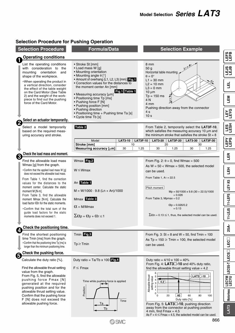
• Stroke St [mm]• Load mass W [g]• Mounting orientation• Mounting angle θ [°]• Amount of overhang (L1, L2, L3) [mm]• Correction values for the distances to the moment center An [mm]
• Measuring accuracy [µm]• Positioning time Tp [ms]• Pushing force F [N]• Pushing position [mm]• Pushing direction• Positioning time + Pushing time Ta [s]• Cycle time Tb [s]
Fig.1
Fig.2
Fig.3
Fig.4
Table 2
Table 1
Table 3
Fig.1 Table 1
Operating conditions1
8 mm50 gHorizontal table mountingθ = 0°L1 = 30 mmL2 = 10 mmL3 = 0 mm10 µmTp = 150 ms4 N4 mmPushing direction away from the connector4 s10 s
List the operating conditions with consideration to the mounting orientation and shape of the workpiece.
*When operating the product in a vertical direction, consider the effect of the table weight on the Card Motor (See Table 2) and the weight of the work-piece to find out the pushing force of the Card Motor.
Select an actuator temporarily.2
Select a model temporarily based on the required meas-uring accuracy and stroke.
From Table 2, temporarily select the LAT3F-10, which satisfies the measuring accuracy 10 µm and the minimum stroke that satisfies the stroke St = 8
Check the positioning time.4
Mp = 50/1000 x 9.8 (30 + 22.5)/1000= 0.026
From Table 3, Mpmax = 0.2
αp = 0.026/0.2 = 0.13
Σαn = 0.13 1, thus, the selected model can be used.
From Table 1, A1 = 22.5
From Fig. 3: St = 8 and W = 50, find Tmin = 100
As Tp = 150 Tmin = 100, the selected model
can be used.
Find the shortest positioning time Tmin [ms] from the graph.*Confirm that the positioning time Tp [ms] is
longer than the minimum positioning time.
Check the load mass and moment.3
From Fig. 2: θ = 0, find Wmax = 500
As W = 50 < Wmax = 500, the selected model
can be used.
Find the allowable load mass Wmax [g] from the graph.
*Confirm that the applied load mass W [g] does not exceed the allowable load mass.
From Table 1, find the correction values for the distances to the moment center. Calculate the static moment M [N·m].From Table 3, find the allowable moment Mmax [N·m]. Calculate the load factor αn for the static moments.
*Confirm that the total sum of the guide load factors for the static moments does not exceed 1.
Selection Procedure Formula/Data Selection Example
Selection Procedure for Pushing Operation
Check the pushing force.5
Duty ratio = Ta/Tb x 100
F Fmax
Duty ratio = 4/10 x 100 = 40%From Fig. 4: LAT3-10 and 40% duty ratio, find the allowable thrust setting value = 4.2
From Fig. 5: LAT3-10, pushing direction away from the connector at pushing position 4 mm, find Fmax = 4.5As F = 4 Fmax = 4.5, the selected model can be used.
Calculate the duty ratio [%].
Find the allowable thrust setting value from the graph.From Fig. 5, find the allowable push ing force Fmax [N] generated at the required pushing position and for the allowable thrust setting value.Confirm that the pushing force F [N] does not exceed the allowable pushing force.
Pitch moment
Wmax
W Wmax
Model LAT3-10 LAT3F-10 LAT3-20 LAT3F-20 LAT3-30 LAT3F-30Stroke [mm] 10 20 30Measuring accuracy [µm] 30 1.25 30 1.25 30 1.25
866
Model Selection Series LAT3
LE
FS
LE
FB
LE
LL
EJS
LE
JBL
EM
LE
YL
EY
GL
ES
LE
SH
LE
PY
LE
PS
LE
RL
EH
LEY-
X511
-LEF
S11
-LEJ
S25
A-
LEC
YMLE
CYU
LECS
S-T
LA
T3
Moto
rless
LEC
S
LE
C

0
50
100
150
200
250
300
600
300
200
150
120
100
0 5 10 15 20 25 30Stroke (Positioning distance) St [mm]
Sho
rtes
t pos
ition
ing
time
Tm
in [m
s]
Fre
quen
cy [c
pm]
W = 0W = 100
W = 200
W = 300
W = 400Load mass W = 500
600
150
200
300
120
100
86
75
Fre
quen
cy [c
pm]
0
50
100
150
200
250
300
350
400
0 5 10 15 20 25 30Stroke(Positioning distance) St [mm]
Sho
rtes
t pos
ition
ing
time
Tm
in [m
s]
W = 0W = 100
W = 200
W = 300W = 400
Load mass W = 500
Mp
W
L1 A1
My
W
L1 A1
Mr
W
Mr
W
L2 A2
L3
Mp
W
L2 A2
My
W
L3
0.0
100
200
300
400
500
600
0(Horizontal)
15 30 45 60 75 90 (Vertical)Mounting angle θ [°]
Allo
wab
le lo
ad m
ass
Wm
ax [g
]
LAT3-10, -20
LAT3-30
Mounting angleθ
LoadCard Motor
Movement direction
0
1
2
3
4
5
6
0 20 40 60 80 100
Duty ratio [%]
Allo
wab
le th
rust
set
ting
valu
e
LAT3-10
LAT3-20
LAT3-30
Fig. 1
Fig. 2
Fig. 3
Amount of Overhang: Ln [mm], Correction Value for the Distances to the Moment Center: An [mm] Correction Value for the Distances to the Moment Center: An [mm]
Table 1
Allowable Load Mass: Wmax [g]
LAT3- LAT3F-
Operating conditionsModel: LAT3F-Mounting orientation: Horizontal/VerticalStep data input version: Cycle time entry method (Triangular movement profile)
Shortest Positioning Time: Tmin [ms] (These are only reference values.)
Operating conditionsModel: LAT3-Mounting orientation: Horizontal/VerticalStep data input version: Cycle time entry method (Triangular movement profile)
Selection
Caution1. The temperature increase of the Card Motor varies depending on the duty ratio and the heat dissipation properties of
the base it is mounted onto. If the temperature of the Card Motor becomes high, reduce the duty ratio by increasing the cycle time, or improve the heat transfer properties of the mounting base and the surroundings.
2. The pushing force generated by the Card Motor varies in relation to the thrust setting value depending on the pushing position and the pushing direction. Refer to Fig. 5 for details.
Fig. 4 Allowable Thrust Setting Value
Series LAT3Model Selection 2
Model A1 A2
LAT3-10 22.5 2.2
LAT3-20 32.5 2.2
LAT3-30 42.5 2.2
Mounting orientation Mp: Pitching My: Yawing Mr: Rolling
Horizontal
Vertical
867

40A1
40A1
40
0
1
2
3
4
5
6
0 2 4 6 8 10
Pushing position [mm]
Pus
hing
forc
e [N
] Thrust setting value: 5
Thrust setting value: 3
Thrust setting value: 1
0
1
2
3
4
5
6
0 5 10 15 20Pushing position [mm]
Pus
hing
forc
e [N
]
Thrust setting value: 4.8
Thrust setting value: 2.8
Thrust setting value: 1
0
1
2
3
4
5
6
0 5 10 15 20 25 30Pushing position [mm]
Pus
hing
forc
e [N
] Thrust setting value: 3.9
Thrust setting value: 2.6
Thrust setting value: 1
0
1
2
3
4
5
6
0 2 4 6 8 10Pushing position [mm]
Pus
hing
forc
e [N
]
Thrust setting value: 5
Thrust setting value: 3
Thrust setting value: 10
1
2
3
4
5
6
0 5 10 15 20Pushing position [mm]
Pus
hing
forc
e [N
]
Thrust setting value: 4.8
Thrust setting value: 2.8
Thrust setting value: 10
1
2
3
4
5
6
0 5 10 15 20 25 30Pushing position [mm]
Pus
hing
forc
e [N
]
Thrust setting value: 3.9
Thrust setting value: 2.6
Thrust setting value: 1
0.00
0.01
0.02
0.03
0.04
0.05
0 2 4 6
Load [N]
Tab
le d
ispl
acem
ent [
mm
]
0.00
0.01
0.02
0.03
0.04
0.05
0 2 4 6
Load [N]
Tab
le d
ispl
acem
ent [
mm
]
0.00
0.02
0.04
0.06
0.08
0 2 4 6
Load [N]
Tab
le d
ispl
acem
ent [
mm
]
Pushingforce
Opposite side of the connectorConnector side
Pushing force
Opposite side of the connectorConnector side
Pushing force: F [N] characteristics (Reference)
LAT3-10 LAT3-20 LAT3-30
LAT3-10, -20, -30 LAT3-10, -20, -30 LAT3-10, -20, -30
Table 2 Table 3Stroke: St [mm], Positioning Repeatability [µm], Measuring Accuracy [µm], Table Weight [g] Allowable Moment: Mmax [N·m]
Table Displacement (Reference)Table displacement due to pitch moment load
Pushing direction away from the connector
Pushing direction toward the connector
Table displacement due to yaw moment load Table displacement due to roll moment load
Displacement through the entire stroke when a load is applied to the point indicated by the arrow
LAT3-10 LAT3-20 LAT3-30
Operating conditionsMounting orientation: Horizontal table mountingThrust setting value: Minimum, continuous, instantaneous maximum of each model.
Table start position: Retracted end (Connector side)Pushing direction: Away from the connectorPushing position: Positioning distance from the connector side, retracted end
Operating conditionsMounting orientation: Horizontal table mountingThrust setting value: Minimum, continuous, instantaneous maximum of each model.
Table start position: Extended end (Opposite side of the connector)Pushing force direction: Toward the connectorPushing position: Positioning distance from the connector side, retracted end
ModelPitch moment/Yaw moment Mpmax, Mymax
Roll momentMrmax
LAT3-10 0.2 0.2LAT3-20 0.3 0.2LAT3-30 0.4 0.2
Model LAT3-10 LAT3F-10 LAT3-20 LAT3F-20 LAT3-30 LAT3F-30Stroke [mm] 10 20 30Positioning repeatability [µm] ±90 ±5 ±90 ±5 ±90 ±5Measuring accuracy [µm] 30 1.25 30 1.25 30 1.25Table weight [g] 50 70 90
Fig. 5
868
Model Selection Series LAT3
LE
FS
LE
FB
LE
LL
EJS
LE
JBL
EM
LE
YL
EY
GL
ES
LE
SH
LE
PY
LE
PS
LE
RL
EH
LEY-
X511
-LEF
S11
-LEJ
S25
A-
LEC
YMLE
CYU
LECS
S-T
LA
T3
Moto
rless
LEC
S
LE
C

System Construction/General Purpose I/O
VCard MotorSeries LAT3
VCounter cable*LATH3-m
LATCA
Counter plug(Accessory)
Separately sold products
VMulti-counterCEU5
PC (Provided by customer)
Communication cableV
VUSB cable(A-mini B type)
Note) When conformity to UL is required, the electric actuator and controller should be used with a UL1310 Class 2 power supply.
Provided by customer
* Option: Can be ordered in the “How to Order” for the Card Motor.* Accessory: Attached to the controller* Separately sold products: Order separately. Refer to pages 894 to 896 for details.
VPower supply plug (Accessory)<Applicable cable size>AWG20 (0.5 mm2)
Power supply for I/O signal 24 VDC Note)
PLC
Provided by customer
Controller power supply 24 VDC Note)
VCard motor controller (Option)
Controller setting software
Power supply for Multi-counter
24 VDC/100 VAC
To CN4
To CN5
To CN3
To CN2
To CN1
Card Motor Controller Series LATCA
V I/O cable (Option)LATH2-mLATH5-m
Actuator cable (Option)VLATH1-m
VController setting kitLATC-W2ContentsqController setting softwarewController setting cable
(Communication cable, USB cable)
869A

System Construction/Pulse Signal
LATCA
VCard motorcontroller (Option)
Counter plug(Accessory)
Actuator cable (Option)VLATH1-m
* Option: Can be ordered in the “How to Order” for the Card Motor.* Accessory: Attached to the controller* Separately sold products: Order separately. Refer to pages 894 to 896 for details.
VPower supply plug (Accessory)<Applicable cable size>AWG20 (0.5 mm2)
V I/O cable (Option)LATH5-m
Power supply for I/O signal 24 VDC Note)
PLC
Provided by customer
VCard MotorSeries LAT3
VCounter cable*LATH3-m
VController setting kitLATC-W2
VMulti-counterCEU5
Communication cableV
VUSB cable(A-mini B type)
ContentsqController setting softwarewController setting cable
(Communication cable, USB cable)
Card Motor Controller Series LATCA
To CN4
To CN5
To CN3
To CN2
To CN1
Note) When conformity to UL is required, the electric actuator and controller should be used with a UL1310 Class 2 power supply.
Provided by customer
Controller power supply 24 VDC Note)
Separately sold products
PC (Provided by customer)
Controller setting software
Power supply for Multi-counter
24 VDC/100 VAC
870
LE
FS
LE
FB
LE
LL
EJS
LE
JBL
EM
LE
YL
EY
GL
ES
LE
SH
LE
PY
LE
PS
LE
RL
EH
LEY-
X511
-LEF
S11
-LEJ
S25
A-
LEC
YMLE
CYU
LECS
S-T
LA
T3
Moto
rless
LEC
S
LE
C
A

RS485Original protocol
System Construction/Serial Communication (One controller)
VCard motorcontroller (Option)
Counter plug(Accessory)
Separately sold productsProvided by customer
ContentsqController setting softwarewController setting cable (Communication cable, USB cable)
* Option: Can be ordered in the “How to Order” for the Card Motor.* Accessory: Attached to the controller* Separately sold products: Order separately. Refer to pages 894 to 896 for details.
VController setting kitLATC-W2
Master equipment (PLC etc.)
orPLC
PC (Provided by customer) Communication cableV
VUSB cable(A-mini B type)Controller
setting software
VActuator cable (Option)LATH1-m
VCard MotorSeries LAT3
VCommunication cable (Separately sold product)LATH6-m
LATCA
VPower supply plug (Accessory)<Applicable cable size>AWG20 (0.5 mm2)
To CN4
To CN3
To CN3
To CN2
To CN1
Card Motor Controller Series LATCA
Note) When conformity to UL is required, the electric actuator and controller should be used with a UL1310 Class 2 power supply.
Provided by customer
Controller power supply 24 VDC Note)
871A

Up to 16 controllersare connectable
RS485Original protocol
System Construction/Serial Communication (2 to 16 controllers)
Communication cableV (Separately sold product)
LEC-CG1-m
VCable between branches (Separately sold product)LEC-CG2-m
VBranch connector (Separately sold product)LEC-CGD
VTerminating resistor connector (Separately sold product)LEC-CGR
VCard MotorSeries LAT3
Actuator cable (Option)VLATH1-m
Counter plug(Accessory)
* Option: Can be ordered in the “How to Order” for the Card Motor.* Accessory: Attached to the controller* Separately sold products: Order separately. Refer to pages 894 to 896 for details.
VCard motor controller (Option)LATCA
Master equipment (PLC etc.)
PLC
To CN4
To CN4
To CN1To CN1 To CN1
To CN2 To CN2To CN2To CN3 To CN3 To CN3
To CN4
Card Motor Controller Series LATCA
Provided by customer
Note) When conformity to UL is required, the electric actuator and controller should be used with a UL1310 Class 2 power supply.
Provided by customer
Controller power supply 24 VDC Note)
VPower supply plug (Accessory)<Applicable cable size>AWG20 (0.5 mm2)
VPower supply plug (Accessory)<Applicable cable size>AWG20 (0.5 mm2)
VPower supply plug (Accessory)<Applicable cable size>AWG20 (0.5 mm2)
BranchVcommunication cable(Separately sold product)
LATH7-m
872
LE
FS
LE
FB
LE
LL
EJS
LE
JBL
EM
LE
YL
EY
GL
ES
LE
SH
LE
PY
LE
PS
LE
RL
EH
LEY-
X511
-LEF
S11
-LEJ
S25
A-
LEC
YMLE
CYU
LECS
S-T
LA
T3
Moto
rless
LEC
S
LE
C
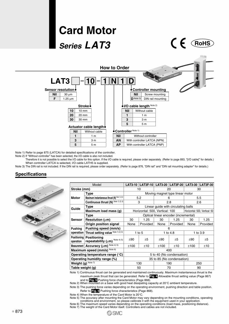
Note 1) Continuous thrust can be generated and maintained continuously. Maximum instantaneous thrust is the maximum peak thrust that can be generated. Refer to Fig. 4 Allowable thrust setting value (Page 867) and to Fig. 5 Pushing force characteristics (Page 868).
Note 2) When mounted on a base with good heat dissipating capacity at 20°C ambient temperature.Note 3) The pushing force varies depending on the operating environment, pushing direction and table position.
Refer to Fig. 5 Pushing force characteristics (Page 868).Note 4) When the temperature of the Card Motor is 20°C.Note 5) The accuracy after mounting the Card Motor may vary depending on the mounting conditions, operating
conditions and environment, so please calibrate it with the equipment used in your application.Note 6) The maximum speed varies depending on the operating conditions (load mass, positioning distance).Note 7) The weight of the Card Motor itself. Controllers and cables are not included.
How to Order
1 N 1 DLAT3 10Sensor resolution Controller mounting
Note 1) Refer to page 875 (LATCA) for detailed specifications of the controller.Note 2) If “Without controller” has been selected, the I/O cable is also not included.
Therefore it is not possible to select the I/O cable for this option. If the I/O cable is required, please order separately. (Refer to page 893, “[I/O cable]” for details.) When controller LATCA is selected, I/O cable LATH5 is supplied.
Note 3) The DIN rail is not included. If the DIN rail is required, please order separately. (Refer to page 876, “DIN rail” and “DIN rail mounting adapter” for details.)
Nil Screw mounting
D Note 3) DIN rail mounting
I/O cable length Note 2)
Nil Without cable
1 1 m
3 3 m
5 5 m
Controller Note 1)
Nil Without controller
AN With controller LATCA (NPN)
AP With controller LATCA (PNP)
Stroke10 10 mm
20 20 mm
30 30 mm
Nil 30 μm
F 1.25 μm
Actuator cable lengthNil Without cable
1 1 m
3 3 m
5 5 m
Card MotorSeries LAT3
Specifications
Model LAT3-10 LAT3F-10 LAT3-20 LAT3F-20 LAT3-30 LAT3F-30Stroke (mm) 10 20 30
MotorType Moving magnet type linear motorMaximum instantaneous thrust (N) Note 1) 2) 3) 5.2 6 5.5Continuous thrust (N) Note 1) 2) 3) 3 2.8 2.6
GuideType Linear guide with circulating ballsMaximum load mass (g) Horizontal: 500, Vertical: 100 Horizontal: 500, Vertical: 50
SensorType Optical linear encoder (incremental)Resolution (μm) 30 1.25 30 1.25 30 1.25Origin position signal None Provided None Provided None Provided
Pushing operation
Pushing speed (mm/s) 6Thrust setting value Note 1) 2) 3) 1 to 5 1 to 4.8 1 to 3.9
Positioning operation
Positioningrepeatability (μm) Note 4) 5) ±90 ±5 ±90 ±5 ±90 ±5
Measurement Accuracy (μm) Note 4) 5) ±100 ±10 ±100 ±10 ±100 ±10Maximum speed (mm/s) Note 6) 400Operating temperature range (°C) 5 to 40 (No condensation)Operating humidity range (%) 35 to 85 (No condensation)Weight (g) Note 7) 130 190 250Table weight (g) 50 70 90
RoHS
873A

depth 2+0.03
0ø3
7.5
dept
h 2
+0.
05 0
3
3.5
6.5
Not
e 2)
Note 2)
Rail dowel pin hole
7
4.7
ø5.
2
depth 1.5+0.03 0ø3
depth 1.5+0.05 03
3.5(R43)
Minimum cable bending radius
Note 2)
Note 1)
Note 2)
Table dowel pin hole
(Rail dowel pin hole)
E
Stroke: A
G 20±0.1
23 68
20 (Fix this part of the cable.)
20
Actuator cable
C x M3 x 0.5 depth 2.5Table mounting screw hole
DB
259.5
HTable
Rail
32
49 (
Tab
le w
idth
)
50
9
F
24
Note 1)4 x M3 x 0.5 depth 2Rail mounting screw hole
32±0.116
Dimensions
LAT3-
Note 1) Refer to page 898 regarding Specific Product Precautions for the mounting screws.Note 2) The length of the part of the dowel pin inserted into the positioning hole should be shorter
than the specified depth.Note 3) This drawing shows the origin position.Note 4) The origin positions G and H are reference dimensions (guide). Refer to page 892 for
details on the origin position.[mm]
ModelStroke Table dimensions Rail dimensions Origin position Note 4)
A B C D E F G H
LAT3-10 10 49 4 — 60 50 4 10.5
LAT3-20 20 69 6 25 90 80 14 20.5
LAT3-30 30 89 6 25 120 110 24 30.5
874
Card Motor Series LAT3
LE
FS
LE
FB
LE
LL
EJS
LE
JBL
EM
LE
YL
EY
GL
ES
LE
SH
LE
PY
LE
PS
LE
RL
EH
LEY-
X511
-LEF
S11
-LEJ
S25
A-
LEC
YMLE
CYU
LECS
S-T
LA
T3
Moto
rless
LEC
S
LE
C

How to Order
Note 1) Either the step data input type or pulse input type can be selected after purchase.Note 2) Do not use a power supply of “inrush current limited” type for the controller.Note 3) Rated current: Current consumption when continuous thrust is generated. Peak current: Current consumption when maximum instantaneous thrust is generated.Note 4) Specification for the connection of the separately sold multi-counter (CEU5).Note 5) Cables are not included.Note 6) This setting software is not supplied with the controller. Order it separately (Refer to page 896 for details).Note 7) Setting cable is included with the controller setting kit.
Note 1) I/O cable LATH5-m is supplied. The actuator cable, the counter cable and the controller setting cable are not supplied with the controller. Refer to pages 893 to 896 for options.
Note 2) The DIN rail is not included. If the DIN rail is required, please order separately. (Refer to page 876.)
LATCA NOption
I/O cable (with shield) length Note 1)
Parallel I/O type
Controller for the Card Motor
Specifications
Model LATCASetting method Note 1) Step data input type Pulse input type
Compatible actuator Card Motor series LAT3
Number of axis 1 axis
Power supply Note 2) Power supply voltage: 24 VDC ±10%, Current consumption Note 3) : Rated 2 A (Peak 3 A) , Power consumption Note 3) : 48 W (Maximum 72 W)
Control system Closed loop
Movement modes Positioning operation, Pushing operation
Number of step data 15 points 4 points
Parallel input 6 inputs (Optically isolated)
Parallel output 4 outputs (Optically isolated, open collector output)
Pulse input mode —Pulse and direction control mode
CW and CCW control modeQuadrature control mode
Pulse signal inputmaximum frequency
—100 kHz (Open collector)
200 kHz (Differential)
Position display output Note 4) A-phase and B-phase pulse signals, RESET signal (NPN open collector output)
Serial communication RS485 (Original protocol)
LED indicator 2 LED’s (Green and Red)
Cooling method Natural air-cooling
Operating temperature range 0 to 40°C (No condensation)
Operating humidity range 90% or less (No condensation)
Insulation resistance Between case and FG: 50 MΩ (500 VDC)
Weight Note 5) Screw mounting: 130 g, DIN rail mounting: 150 g
Controller setting kit Note 6) LATC-W2
Setting cable Note 7) LEC-W2-C, LEC-W2-U (Same cable as included with LEC-W2)
N NPN
P PNP
Nil Without cable
1 1 m
3 3 m
5 5 m
Nil Screw mounting
D Note 2) DIN rail mounting
Series LATCA
Card Motor Controller(Step Data Input Type/Pulse Input Type)
875
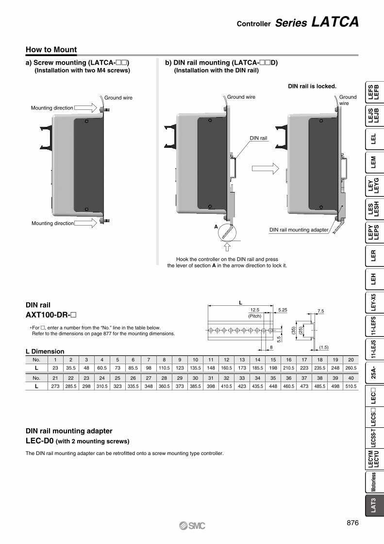
Ground wire
Mounting direction
Mounting direction
DIN rail
Ground wire Groundwire
ADIN rail mounting adapter
L
7.5
(25)
(35)
5.5
5.2512.5(Pitch)
8 (1.5)
a) Screw mounting (LATCA-)(Installation with two M4 screws)
b) DIN rail mounting (LATCA-D)(Installation with the DIN rail)
DIN rail is locked.
Hook the controller on the DIN rail and press the lever of section A in the arrow direction to lock it.
DIN railAXT100-DR-
*For , enter a number from the “No.” line in the table below. Refer to the dimensions on page 877 for the mounting dimensions.
L Dimension
DIN rail mounting adapterLEC-D0 (with 2 mounting screws)
The DIN rail mounting adapter can be retrofitted onto a screw mounting type controller.
How to Mount
No. 1 2 3 4 5 6 7 8 9 10 11 12 13 14 15 16 17 18 19 20
L 23 35.5 48 60.5 73 85.5 98 110.5 123 135.5 148 160.5 173 185.5 198 210.5 223 235.5 248 260.5
No. 21 22 23 24 25 26 27 28 29 30 31 32 33 34 35 36 37 38 39 40
L 273 285.5 298 310.5 323 335.5 348 360.5 373 385.5 398 410.5 423 435.5 448 460.5 473 485.5 498 510.5
876
Controller Series LATCA
LE
FS
LE
FB
LE
LL
EJS
LE
JBL
EM
LE
YL
EY
GL
ES
LE
SH
LE
PY
LE
PS
LE
RL
EH
LEY-
X511
-LEF
S11
-LEJ
S25
A-
LEC
YMLE
CYU
LECS
S-T
LA
T3
Moto
rless
LEC
S
LE
C

35
31
141
132
150
4.6for body mounting
Alarm LED (Red)(When the LED is lit or flashing: Alarm)
CN5: Parallel I/O connector
CN4: Counter connector
CN3: Serial I/O connector
CN2: Motor connector
CN1: Power supply connector
66
81.7
1
Power supply LED (Green)When the LED is lit: Power ONWhen the LED is flashing: Alarm ø4.5
for body mounting
31
35
132
150
167.
3 (W
hen
the
DIN
rai
l mou
ntin
g ad
apte
r is
in lo
cked
pos
ition
)
173.
2 (W
hen
the
DIN
rai
l mou
ntin
g ad
apte
r is
in u
nloc
ked
posi
tion)
66
(81.7)
64.2
35
(91.7)
1
(11.5)Refer to page 876 for L dimension and part number of DIN rail.
a) Screw mounting (LATCA-)
b) DIN rail mounting (LATCA-D)
Note) When two or more controllers are used, the space between the controllers should be 10 mm or more.
Dimensions
877
Series LATCA

24 VDC power supplyfor the output signals
Pulse input circuitPulseinputinternalcircuit
∗ Maximum output current 10 mA
Mai
n ci
rcui
t
∗ The power supply can be either polarity.
24 VDC power supplyfor the input signals
CN5
Internalresistance
10 [kΩ]
A1
A2
A3
A4
A5
A6
A7
A8
A9
A10
B1
B2
B3
B4
B5
B6
B7
B8
B9
B10
DC
1(−
)D
C1(
+)
Pha
seB
Pha
seA
GN
DR
ES
ET
FG
Note) When using the controller by the step data input type, do not wire as there is an internal circuit to use terminals B7 to B10 as the pulse signal input terminals.
Power Supply Connector: CN1
Power Supply Connector Terminal
Counter Connector: CN4
Counter Connector Terminal
∗The counter plug is an accessory (supplied with the controller).
∗Use the counter cable (LATH3-) for connecting the counter to the counter plug.
Parallel I/O Connector: CN5
Power supply plug Counter plug
∗Use the I/O cable (LATH5-) to connect a PLC, etc., to the CN5 parallel I/O connector.∗The wiring is specific to the type of parallel I/O (NPN or PNP). Please refer to the wiring diagrams below for correct wiring of NPN and PNP type controllers.
∗The power supply plug is an accessory (supplied with the controller).Use an AWG20 (0.5 mm2) cable for connecting the power supply plug to a 24 VDC power supply.
Wiring Example
Terminal name Function Details
DC1 (−)Power supply (−)
The negative (−) power supply terminal to the controller.Power (−) is also supplied to the Card Motor via the internal circuit of the controller and actuator cable.
DC1 (+)Powersupply (+)
The positive (+) power supply terminal to the controller.Power (+) is also supplied to the Card Motor via the internal circuit of the controller and actuator cable.
Name Details Cable colorPhaseB Connect to the phase B wire of the counter cable. WhitePhaseA Connect to the phase A wire of the counter cable. Red
GND Connect to the GND wire of the counter cable. Light grayRESET Connect to the Reset wire of the counter cable. Yellow
FG Connect to the FG wire of the counter cable. Green
NPN PNP
878
Controller Series LATCA
LE
FS
LE
FB
LE
LL
EJS
LE
JBL
EM
LE
YL
EY
GL
ES
LE
SH
LE
PY
LE
PS
LE
RL
EH
LEY-
X511
-LEF
S11
-LEJ
S25
A-
LEC
YMLE
CYU
LECS
S-T
LA
T3
Moto
rless
LEC
S
LE
C

B7B8B9B10
PP+PP–NP+NP–
B7B8B9B10
PP+PP–NP+NP–
Counts by L
Counts by L
Counts by H and L
HLPP
NP
NP
HLPP
NP
HLPP
Pulse and direction control mode
CW and CCW control mode
Quadrature control mode
B7
B8
B9
B10
<No. 1>
<No. 2>
<No. 3>
<No. 4>
<No. 5>
<No. 6>
R1
R2
R3
R1
R2
R3
Pul
se in
put
sign
al s
witc
h
Mai
n ci
rcui
t
Wiring Example
Input/Output Signal
Input/Output Signal
Terminal no. Input/Output Function DetailsA1
Input
COM Connect a 24 VDC power supply for the input signals. (Polarity is reversible)A2 IN0
Selection of step data numberspecified by a Bit No.
(combinations of IN0 to IN3)
A3 IN1A4 IN2A5 IN3A6 DRIVE Command to drive the motorA7 SVON Command to turn the servo motor ONA8 NC Not connectedA9 NC Not connectedA10 NC Not connectedB1
Output
DC2 (+) Connect the 24 V power supply terminal for the output signals.B2 DC2 (−) Connect the 0 V power supply terminal for the output signals.B3 BUSY ON when the actuator is moving Note 1)
B4 ALARM OFF when an alarm has been generated Note 2)
B5 OUT0 Select an output function among BUSY, INP, INFP, INF, AREA A and AREA B. Note 3)B6 OUT1
B7
Input
NC Not connectedB8 NC Not connectedB9 NC Not connectedB10 NC Not connected
Note 1) Other output functions can also be assigned to the BUSY output.Note 2) This output signal turns ON when power is supplied to the controller, but turns OFF in alarm condition (N.C.).Note 3) INP is set as a default for OUT0, and INF for OUT1.
Terminal no. Input/Output Function DetailsA1
Input
COM Connect a 24 VDC power supply for the input signals. (Polarity is reversible)A2 IN0 Selection of step data number specified by a Bit No.
(combinations of IN0 and IN1)A3 IN1A4 SETUP Instruction to return to originA5 CLR Deviation resetA6 TL Instruction to pushing operationA7 SVON Command to turn the servo motor ONA8 NC Not connectedA9 NC Not connectedA10 NC Not connectedB1
Output
DC2 (+) Connect the 24 V power supply terminal for the output signals.B2 DC2 (−) Connect the 0 V power supply terminal for the output signals.B3 BUSY ON when the actuator is moving Note 1)
B4 ALARM OFF when an alarm has been generated Note 2)
B5 OUT0 Select an output function among BUSY, INP,INFP, INF, AREA A and AREA B. Note 3)B6 OUT1
B7
Input
PP+
Connect the pulse input signal Note 4)B8 PP−B9 NP+B10 NP−
Note 1) Other output functions can also be assigned to the BUSY output.Note 2) This output signal turns ON when power is supplied to the controller, but turns OFF in alarm condition (N.C.).Note 3) INP is set as a default for OUT0, and INF for OUT1.Note 4) The function assignment changes according to the pulse input
mode.
Pulse Input Type
OUT0 and OUT1 Optional Output Functions Note)
Name DetailsBUSY ON when the actuator is moving Note 1)
INPON when the table is within the “INP” output range
of the current “Target Position”.
INFPON when the table is within the positioning
repeatability range of the actuator for the current “Target Position”.
INFON when the pushing force is within the
“Threshold Force Value”.AREA A, AREA B ON when the table is within the set “Area Ranges”.
Note) One output function can be selected for each OUT0 and OUT1.
Signal input method
Pulse input signalpower supply voltage
Pulse input signalswitch setting
Current limiting resistor R specifications
(a) Opencollector input
24 VDC ±10% No. 2 & No. 5: ON, Others: OFF R2 = 1.5 kΩ(b) 5 VDC ±5% No. 1 & No. 4: ON, Others: OFF R1 = 220 Ω(c) Differential input — No. 3 & No. 6: ON, Others: OFF R3 = 120 Ω
Step Data Input Type
Pulse Input Circuit ExamplePulse signal output of positioning unit is open collector output
Change the switch in the controller according to the pulse input signal power supply voltage.
Pulse signal power supply (24 VDC or 5 V )
Pulse signal output of positioning unit is differential output
Pulse Input Mode
Pulse Input Internal Circuit
Table moves to opposite side of connector
1 2 3 4 5 6 1 2 3 4 5 6 1 2 3 4 5 6
ONONON
(a) Open collector input (24 V) (b) Open collector input (5 V) (c) Differential input (24 V)
Table moves to connector side
879
Series LATCA

Power supply
IN0 to 3
SVON
DRIVE
BUSY
ALARM
Input
Output
Speed
Return to origin
24 V 0 V
ONOFF
0 mm/s
ONOFF
The INP output turns ON after the return to origin has been completed.
The Alarm output turns ON after the controller has been initialized.
OUT0(INP)
The controller scans the step data number.
The SVON input turns ON after the ALARM output has turned ON.
Power supply
IN0 to 3
SVON
DRIVE
BUSY
Input
Output
SpeedPositioning operation
ONOFF
0 mm/s
ONOFF
The INP output turns ON when the Card Motor table is within the INP output range of the "Target Position". The INP signal will turn OFF again if the table moves outside the INP output range.
OUT0(INP)
24 V 0 V
The controller scans the step data number.
Set the step data no.
Power supply
Input
Output
The INF output turns ON when the pushing force exceeds the set "threshold" pushing force value.The INF signal turns OFF when the DRIVE signal is turned OFF.
IN0 to 3
SVON
DRIVE
BUSY
SpeedPushing operation
ONOFF
0 mm/s
ONOFF
OUT1(INF)
24 V 0 V
Set the step data no.
The controllerscans the stepdata number.
AREA B (Position 2)AREA B (Position 1)
AREA A (Position 2)AREA A (Position 1)
AREA A
AREA B
ON
OFFONOFF
SVON
ALARM
Input
Output
ONOFF
ONOFF
Alarm out
Alarm reset
Remove the cause of the alarm.
∗ “ALARM” is expressed as negative-logic circuit.
∗ “ALARM” is expressed as negative-logic circuit.∗ Select the AREA signal for the parallel output (OUT0 or OUT1).
Return to Origin
Positioning Operation
Alarm Reset
Pushing Operation
Signal Timing (When step data input type is selected)
Use a 2 msec interval or more between input signals, and maintain the signal state for at least 2 msec.Turn ON the SVON signal first after that the ALARM signal has turned ON
after power has been supplied to the controller. If the SVON signal is already ON, the operation will not start for safety reasons.Keep the DRIVE signal turned ON until the next operation instruc-
tion is given except when stopped during operation.When the DRIVE signal is turned OFF during positioning operation,
the table of the Card Motor stops, and holds the position.When the DRIVE signal is turned OFF during pushing operation, the
pushing operation is completed and this position is retained.
Caution
AREA Signal
Tableposition
Output
880
Controller Series LATCA
LE
FS
LE
FB
LE
LL
EJS
LE
JBL
EM
LE
YL
EY
GL
ES
LE
SH
LE
PY
LE
PS
LE
RL
EH
LEY-
X511
-LEF
S11
-LEJ
S25
A-
LEC
YMLE
CYU
LECS
S-T
LA
T3
Moto
rless
LEC
S
LE
C

AREA B (Position 2)AREA B (Position 1)
AREA A (Position 2)AREA A (Position 1)
AREA A
AREA B
Tableposition
Output
ON
OFFONOFF
SVON
ALARM
Input
Output
ONOFF
ONOFF
Alarm out
Alarm reset
Remove the cause of the alarm.
0 mm/s
ONOFF
Input
Power supply
Output
IN0 to 1
SVON
SETUP
BUSYOUT0(INP)
ALARM
Speed
ON after controllersystem initialization
Return to origin
SVON input ON after ALARM output ON
SETUP input OFF after INP output ON
OFFON
0 V24 V
OUT0 (INP) and BUSY output ON after return to origin has been completed.
NP–PP–
0 mm/s
ONOFF
OFFON0 V24 V
OUT0(INP)
BUSY
SVON
IN0 to 1
Power supply
Input
Output
Speed Positioningoperation
The controller scans the step data number.
Start of pulse input
Set the stepdata no.
OUT0 (INP) output turns ON in the condition where the pulse input signal is not input for 10 ms or more continuously, and the deviation from the target value becomes the positioning width or less.
Power supply
IN0 to 1
SVON
PP–
NP–
TL
BUSY
Input
OutputOUT0(INP)
OUT1(INF)
Speed
Pushingoperation Positioning
operation
24 V 0 VONOFF
0 mm/s
ONOFF
Set the stepdata no.
The controller scansthe step data number.
When the target value by the pulse input signal conforms to the current location, the pushing operation ends and starts the positioning operation.
When TL input turns OFF, OUT1 (INF) signal turns OFF.
OUT0(INP)
OUT1(INF)
Power supply
IN0 to 1
SVON
PP–
NP–
TL
BUSY
Input
Output
Start of pulse inputSet the stepdata no.
The controller scansthe step data number.
OUT0 (INP) output is always OFF when TL signal is ON.
Speed
OUT1 (INF) output turns ON when the generated force exceeds the trigger LV of the INF signal.
When TL input turns ON, the speed slows down to 6 mm/s (Pushing operation start).
24 V 0 VONOFF
6 mm/s0 mm/s
ONOFF
∗ “ALARM” is expressed as negative-logic circuit.
∗ “ALARM” is expressed as negative-logic circuit.∗ Select the AREA signal for the parallel output (OUT0 or OUT1).
Return to Origin Positioning Operation
Alarm Reset
AREA Signal
Turn ON the SVON signal first after that the ALARM signal has turned ON after power has been supplied to the controller. If the SVON signal is already ON, the operation will not start for safety reasons.During the return to origin, do not input a pulse input signal until the SETUP signal has turned OFF. Pulse input signals input while the SETUP signal is turned ON will be invalidated.Do not input the pulse input signals PP and NP at the same time in the CW and CCW control mode.When changing the moving direction of the actuator, be sure to leave an interval of 10 [msec] or more, and input a pulse signal of reverse direction.After the IN0 and IN1 signals are changed, leave an interval of 10 ms or more, then input a pulse input signal.When the amount of movement is less than the following count, positioning control will not be performed.
Input a pulse input signal that is equal to or more than the following count.LAT3— • : 3 counts, LAT3F— • : 4 counts
Caution
Signal Timing (When pulse input type is selected)
Pushing Operation Operation after Pushing Operation
881
Series LATCA

Serial Communication
Communication SpecificationsItem Details
Protocol Original Note)
Communication data ASCII
Node type Slave (Controller)
Error checking None
Frame size Variable length: Max. 128 bytes
Communication method
RS485, asynchronous system
Communication speed 19200 bps
Data bit 8 bit
Parity Even parity
Stop bit 1 bit
Flow control None
Note) Original (command method) is used as the protocol.
qSetting of step dataThe contents of the step data such as the target position and positioning time can be set.
wAcquisition of operation informationInformation such as the status of a parallel I/O signal and table position can be acquired.
eStep data operationWithout inputting a parallel I/O signal, the step data no. can be selected from the communication device of the PLC, etc. via serial communication to specify the operation.
rDirect operationOperation can be executed by setting the target position, positioning time, etc. each time.
Use the controller setting software to set the basic settings (refer to the following) of the controller.1. Select input type2. Card Motor product number3. Return to origin method4. Step data input method5. Card Motor mounting orientation6. Set the controller ID (Set to “1” at the time of shipment) 7. Select output signal
Function
Caution
882
Controller Series LATCA
LE
FS
LE
FB
LE
LL
EJS
LE
JBL
EM
LE
YL
EY
GL
ES
LE
SH
LE
PY
LE
PS
LE
RL
EH
LEY-
X511
-LEF
S11
-LEJ
S25
A-
LEC
YMLE
CYU
LECS
S-T
LA
T3
Moto
rless
LEC
S
LE
C


Speed Vc
Positioning time tp
Acceleration Aa
Positioning distance S
Time [s]
Spe
ed [m
m/s
]
Speed Vc
tp
ta tdtc
Acceleration Aa
Positioning distance S
Time [s]
Spe
ed [m
m/s
]
Deceleration Ad
0
10000
20000
30000
40000
50000
60000
70000
0 100 200 300 400 500
Load mass [g]
Max
imum
acc
eler
atio
n/de
cele
ratio
n [m
m/s
2 ]
Card MotorLAT3-10
LAT3-20
LAT3-30
Speed entrymethod
There are two methods for setting the step data in the Card Motor controller as described below.
Setting items:
To operate the table at a constant speed.The table moves to the set target position based on the set speed, acceleration and deceleration.
Calculate the positioning distance S [mm] between the start posi-tion and the target position. The table will move to the target posi-tion based on the set positioning time tp [s] according to a triangu-lar movement profile as shown in the diagram on the right.* It is not necessary to enter the speed, acceleration and deceler-
ation since they are calculated automatically by the Card Motor Controller Setting Software.
The positioning time should be set longer than the shortest posi-tioning time shown in Fig. 3 on page 867 with consideration to the load mass during the operation. If there is overshoot or vibration, set the positioning time longer.
Cycle Time Entry Method (Positioning Operation)
Target position [mm]
Target position [mm]
Positioning time [s] Load mass [g]
Setting items:
Calculate the positioning distance S [mm] between the start position and the target position. The table will move to the target position based on the set speed Vc [mm/s], acceleration Aa [mm/s2] and deceleration Ad [mm/s2] according to a trapezoidal movement profile as shown in the diagram on the right.
The acceleration and deceleration should be smaller than the maximum acceleration/deceleration with consideration to the load mass during the operation as specified in the diagram on the right.
If the acceleration/deceleration is low, the table may not reach the set speed due to a triangular movement profile.
Refer to the equations below for how to calculate the acceleration,constant velocity and deceleration times and distances.
(Add settling time to the positioning time to obtain the real cycle time.)*The settling time varies depending on the positioning distance
and load mass. 0.15 seconds can be used as a reference value.
Speed Entry Method (Positioning Operation)
Speed [mm/s] Acceleration [mm/s2] Deceleration [mm/s2] Load mass [g]
Acceleration time: ta = Vc / Aa [s]Deceleration time: td = Vc / Ad [s]Acceleration distance: Sa = 0.5 x Aa x ta2 [mm]Deceleration distance: Sd = 0.5 x Ad x td2 [mm] Distance with constant velocity: Sc = S – Sa – Sd [mm]Time with constant velocity: tc = Sc / Vc [s]Positioning time: tp = ta + tc + td [s]
Caution
Step Data Setting Methods and Movement Profiles
Cycle timeentry method
To operate the table based on the target position and positioning time, or to operate it at high frequency.The speed, acceleration and deceleration are calculated automatically after the target position and posi-tioning time have been set.
888
Controller Series LATCA
LE
FS
LE
FB
LE
LL
EJS
LE
JBL
EM
LE
YL
EY
GL
ES
LE
SH
LE
PY
LE
PS
LE
RL
EH
LEY-
X511
-LEF
S11
-LEJ
S25
A-
LEC
YMLE
CYU
LECS
S-T
LA
T3
Moto
rless
LEC
S
LE
C
A

Target position [mm]
Positioning time [s]
Load mass [g]
Basic settingsSet each item described below and register it to the controller by clicking [Setup].[Card Motor Product Number]: Enter the product number of the connected Card Motor.[Return to Origin Method]: Select origin method and position.[Card Motor Mounting Orientation]: Select horizontal or vertical.[Step Data Input Method]: Select cycle time entry method
A
B
C
D
Step 1
Setting of the operating conditions-Selection of operation type-
Select the [Step Data Setup] tab.Select “Operation” type.
Position For transporting a workpiece to a specific position
Pushing For applying force to a workpiece or for measuring the size of a workpiece
Distance from the origin position (or current position) to the target position
Time required to move to the target position
Select the approximate weight of jigs or workpieces mounted on the Card Motor table.
Target position [mm]
Positioning time [s]Thrust setting value
Force to be appliedLoad mass [g]
<Pushing operation> Items to enter
<Positioning operation>Items to enter
Step 2
Setting of the operating conditions-Entering of the operating values-
Step 3
After the operating conditions have been set, Click the [Download] button to complete the settings.
Download the completed settingsStep 4
G
G
H
H
I
I
J
A C
D
G
K
H I
F
E
B
J
E
F
K
+
Cycle Time Entry
The controller automatically calculates the speed, acceleration and deceleration after the user has entered how many seconds it should take for the Card Motor table to move to the target position. Therefore, there is no need to enter the speed, acceleration and deceleration.
Cycle Time Entry Method
* Refer to the operation manual for details.
889
Series LATCA
A

qMoves at high speed
wStops at the target position
Target position
WorkpieceRail Table
Positioning time [s]
qHigh speed
wStop
Spe
ed [m
m/s
]
Target position
wStop
Constant speedqHigh speed
Acceleration
Spe
ed [m
m/s
]
Deceleration
Target position
ePress
qMoves at high speed
Target position
Jig
wLow speed
Rail Table Workpiece
Target positionPositioning time [s]
qHigh speed
wLow speed
ePress
Spe
ed [m
m/s
]
Target position
ePress
qHigh speed
wLow speed
Spe
ed [m
m/s
]
Position
Pushing
The Card Motor controller has two operation modes as described below.
For transporting a workpiece to a specific position
For applying force to a workpiece or for measuring the size of a workpiece.
Cycle Time Entry Method: The acceleration and deceleration are automatically calculated based on the set positioning time, and the table moves according to a triangular movement profile q and stops at the set target position w.Speed Entry Method: The table moves based on the set acceleration, speed and deceleration according to a trapezoidal movement profile q and stops at the target position w.
Positioning Operation
Cycle Time Entry Method: The acceleration and deceleration are automatically calculated based on the set positioning time, and the table moves according to a triangular movement profile close to the target position q, and continues to move at low speed (6 mm/s) until it comes into contact with the workpiece w. After the table has come into contact with the workpiece the Card Motor presses the workpiece e.Speed Entry Method: The table moves based on the set accelera-tion, speed and deceleration according to a trapezoidal movement profile close to the target position q, and continues to move at low speed (6 mm/s) until it comes into contact with the workpiece w. After the table has come into contact with the workpiece the Card Motor presses the workpiece e.
For pushing operations, set the target position at least 1 mm away from the position where the table or the pushing tool comes into contact with the workpiece. Otherwise, the table may hit the workpiece at a speed exceeding the specified 6 mm/s pushing speed, which could damage the workpiece and Card Motor.The pushing force varies from the thrust setting value depending on the operating environment, pushing direction and table position. The thrust setting value is a nominal value. Please calibrate the thrust setting value according to the application requirements.
Pushing Operation
Caution
Movement profile for the Cycle Time Entry Method (Triangular)
Movement profile for the Speed Entry Method (Trapezoidal)
Movement profile for the Cycle Time Entry Method (Triangular)
Movement profile for the Speed Entry Method (Trapezoidal)
Operation Modes
890
Controller Series LATCA
LE
FS
LE
FB
LE
LL
EJS
LE
JBL
EM
LE
YL
EY
GL
ES
LE
SH
LE
PY
LE
PS
LE
RL
EH
LEY-
X511
-LEF
S11
-LEJ
S25
A-
LEC
YMLE
CYU
LECS
S-T
LA
T3
Moto
rless
LEC
S
LE
C
A

MULTI COUNTER:CEU5 A COM COM COMB DC12V GND F.G. R.S. HOLD BANK1 BANK2
COM S.STOPOUT1OUT2OUT3OUT4OUT5AC100~240V
COUNT PRESET FUNC.
SD SGRD RS-232C
UP
LEFT RIGHT
DOWN
SEL. SETMODE
MULTI COUNTER:CEU5 A COM COM COMB DC12V GND F.G. R.S. HOLD BANK1 BANK2
COM S.STOPOUT1OUT2OUT3OUT4OUT5AC100~240V
COUNT PRESET FUNC.
SD SGRD RS-232C
UP
LEFT RIGHT
DOWN
SEL. SETMODE
MULTI COUNTER:CEU5 A COM COM COMB DC12V GND F.G. R.S. HOLD BANK1 BANK2
COM S.STOPOUT1OUT2OUT3OUT4OUT5AC100~240V
COUNT PRESET FUNC.
SD SGRD RS-232C
UP
LEFT RIGHT
DOWN
SEL. SETMODE
Reference plane
Workpiece dimension
Multi-counter(Accessory)
RS232C orBCD signal output
Card Motor ControllerJig
Workpiece
Tool
The amount of table movement is detected by the sensor (encoder) built into the Card Motor for measuring the size of workpieces.
Length Measurement
The area output range preset in the controller is compared with the table position, and the AREA output signals are activated by the controller when the table is within the set range. These signals are used for quality judgement and differentiation of workpieces.
Workpiece Quality Judgement and Differentiation
The multi-counter may lose pulses when a long counter cable is used or the Card Motor is driven at high speed.
Caution
qTouch the referenceplane with the tooland reset the counter.
eTouch the workpiecewith the tool to measurethe size of it.(The counter displays andoutputs the length.)
wReturn the tool.
CEU5 multi-counter settings
Note) The decimal numbers will not be displayed when the resolution is set to "0.00125", because the CEU5 multi-counter has a 6-digit display.
It is possible to output up to 31 preset points using the multi-counter (optional accessory: refer to page 895).
Length measurement, differentiation and quality judgement of workpieces is possible using the multi-counter (optional accessory: refer to page 895) and the AREA outputs of the controller.
Workpiecequality
judgement
Workpiecedifferentiation
Card Motor model LAT3-l LAT3F-lEncoder resolution [μm] 30 5 2.5 1.25 Note)
Connected model MANUALMultiplication factor X4 X1 X2 X4Value per 1 pulse 00.0300 00.0050 00.0025 0.00125Decimal point position **.**** *.*****Input signal type 2PHASE
AREA B signalat stop
ON OFF
AREA A signalat stop
ON Workpiece A —
OFF Workpiece B —
Judgement
AREA A signalat stop
ON OK
OFF NG
Table position Tolerance range
ONOFF
Time
AREA A signal
Table position
Workpiece B range
Workpiece A range
ONOFFONOFF
Time
AREA A signal
AREA B signal
Judgement results
Judgement results
Operation Modes
891
Series LATCA
A

Connector sideOpposite side of the connector
Maximum stroke position
Mechanical end stopper (Extended end)
Stroke: A
Origin position
Mechanical end stopper (Retracted end)
0.30.3 Table
Rail
qThe stopping position of the table when returningto the origin position on the connector side
eThe stopping position of the table when returning to the sensor origin position
wThe stopping position of the table when returning tothe origin position on the opposite side of the connector
J
H
qRetracted end position
(Connector side)
wExtended end position
The default origin position is set to the connector side [Retracted End Position]. The table is moved toward the connector side, returns 0.3 mm and the origin position (0) is set at 0.3 mm away from the mechanical end stop of the table at the connector side.After [Return to Origin] is completed, the table stops at the origin position.
An external jig is used to stop the table of the Card Motor when the [Return to Origin] is performed. The table is moved to the opposite side of the connector, returns 0.3 mm and the origin position is set at 0.3 mm away from the mechanical end stop of the table at the opposite side of the connector. After [Return to Origin] is completed, the table stops at the maximum stroke end (A).
eSensor origin This method is used to achieve high positioning repeatability accuracy of the origin position. Only the LAT3F-, which is equipped with a origin position signal (Z-pulse) in the sensor, can be used with this method. The origin position is set based on the Z-pulse from the integrated sensor (linear encoder).The table is moved to the Z-pulse of the integrated sensor, and the origin position of the table is set at a certain distance (J) away from the Z-pulse when the [Return to Origin] is performed.After [Return to Origin] is completed, the table stops at the sensor origin signal position.
The Card Motor uses an incremental type sensor (linear encoder) to detect the position of the table.Therefore it is necessary to return the table to the origin position after the power has been turned on.There are three [Return to Origin] methods as stated below.In any of the methods, the origin position (0) will be set at the connector side. When the table is moved away from the connector toward the opposite side, after the [Return to Origin] has been performed, the new position of the table is added in the controller (incremental positive direction).
If the table is returned to the origin position by the mechanical end stopper installed in the Card Motor, the origin position
will be set to the position shown below.
Note) Only for the LAT3F-
· The origin position varies depending on the return to origin position method. Please adjust according to the specific equipment used with this product.
· If the return to origin position is performed using an external jig or workpiece to stop the table, the origin position may be set outside of the travel range. Do not set the target position of the step data outside of the Card Motor movable range. It may damage the workpieces and the Card Motor.
Caution
Return to Origin
Model A H J Note)
LAT3-10 10 10.5 5
LAT3-20 20 20.5 5
LAT3-30 30 30.5 15
892
Controller Series LATCA
LE
FS
LE
FB
LE
LL
EJS
LE
JBL
EM
LE
YL
EY
GL
ES
LE
SH
LE
PY
LE
PS
LE
RL
EH
LEY-
X511
-LEF
S11
-LEJ
S25
A-
LEC
YMLE
CYU
LECS
S-T
LA
T3
Moto
rless
LEC
S
LE
C
A
PLC sideController side
ShieldB1A1
(10) L
(18.
6)
I/O cable
Controller side
Raised area
Actuator side
(25.5)
(18)
(25.5)
(21)
(9)
(ø5.
2)
(7)
L
PLC sideController side
A1(Red)
CB
A
Color polarity indication
(Red)
Polarized key
B1A1B1
(Red)
A1(Red)
View C
(10) L
(18.
6)
(6)
(15.
4)
Fused
Fused Fused (10)
Fused (10)
PLCControllerI/O cable
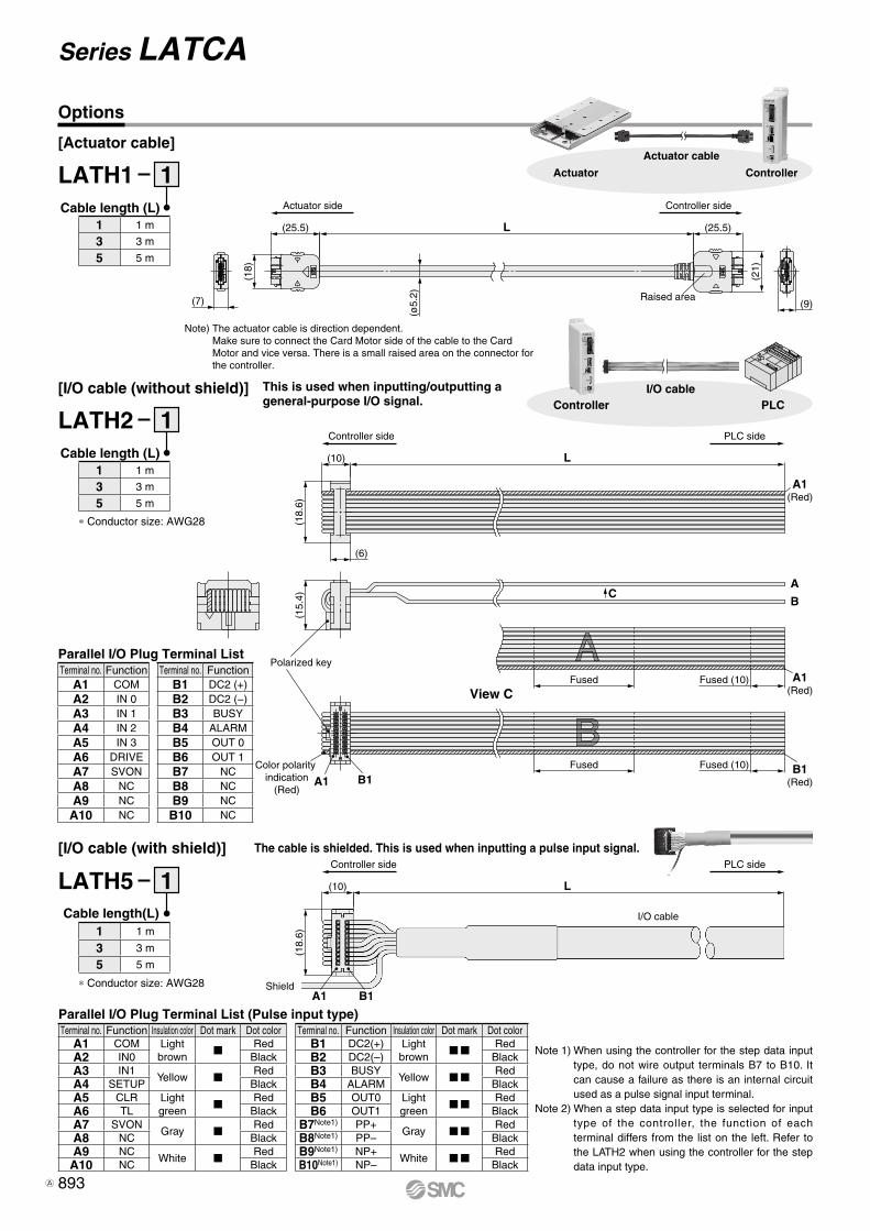
[I/O cable (with shield)]
LATH5 1Cable length(L)
∗ Conductor size: AWG28
Parallel I/O Plug Terminal List (Pulse input type)
Options
Terminal no. Function Insulation color Dot mark Dot colorB1 DC2(+) Light
brownMM Red
B2 DC2(–) BlackB3 BUSY
Yellow MM RedB4 ALARM BlackB5 OUT0 Light
greenMM Red
B6 OUT1 BlackB7Note1) PP+
Gray MM RedB8Note1) PP– BlackB9Note1) NP+
White MM RedB10Note1) NP– Black
Terminal no. Function Insulation color Dot mark Dot colorA1 COM Light
brownM Red
A2 IN0 BlackA3 IN1
Yellow M RedA4 SETUP BlackA5 CLR Light
greenM Red
A6 TL BlackA7 SVON
Gray M RedA8 NC BlackA9 NC
White M RedA10 NC Black
1 1 m
3 3 m
5 5 m
Note 1) When using the controller for the step data input type, do not wire output terminals B7 to B10. It can cause a failure as there is an internal circuit used as a pulse signal input terminal.
Note 2) When a step data input type is selected for input type of the controller, the function of each terminal differs from the list on the left. Refer to the LATH2 when using the controller for the step data input type.
The cable is shielded. This is used when inputting a pulse input signal.
This is used when inputting/outputting a general-purpose I/O signal.
ControllerActuator
Actuator cable[Actuator cable]
LATH1 1Cable length (L)
[I/O cable (without shield)]
LATH2 1Cable length (L)
∗ Conductor size: AWG28
Parallel I/O Plug Terminal List
Note) The actuator cable is direction dependent.Make sure to connect the Card Motor side of the cable to the Card Motor and vice versa. There is a small raised area on the connector for the controller.
Terminal no. FunctionB1 DC2 (+)B2 DC2 (−)B3 BUSYB4 ALARMB5 OUT 0B6 OUT 1B7 NCB8 NCB9 NCB10 NC
Terminal no. FunctionA1 COMA2 IN 0A3 IN 1A4 IN 2A5 IN 3A6 DRIVEA7 SVONA8 NCA9 NC
A10 NC
1 1 m
3 3 m
5 5 m
1 1 m
3 3 m
5 5 m
893
Series LATCA
A

81
4
3
2
1
Up to 16 controllers
are connectable
Multi-counter sideController side
WhiteBlueRedBlack
Yellow
GreenBrown
(7)
(80)
L(40)
(7)
(ø6.
8)
∗1∗1: indicates a twisted pair
cable.
[Cable]
[Communication cable]
[Branch communication cable]
[Branch connector]
[Terminating resistor]
LATH6
LATH7
1
1
Cable length(L)
Cable length(L)
1 1m
1 1m
LEC CG L1 LEC CGD
LEC CGR
Branch connector
Cable between branches
Communication cableCable type1 Communication cable2 Cable between branches
Cable lengthK 0.3 mL 0.5 m1 1 m
Options
PLCControllerCommunication cable
System Construction
Terminal no. Function Insulation color
1 NC —
2 SD+ White
3 FG Shield
4 SD– Black
Branch Communication Plug Terminal List
Branch communicationV cable
(Separately sold product)LATH7-m
VCable between branches (Separately sold product)LEC-CG2-m
VBranch connector (Separately sold product)LEC-CGD
VTerminating resistor connector(Separately sold product)LEC-CGR
Communication cableV(Separately sold product)
LEC-CG1-m
VCard Motor controller(Option)LATCA
Counter plug (Accessory)
To CN2To CN2To CN3
To CN4To CN4
To CN3
Terminal no. Function Insulation color
1 NC —
2 NC —
3 SD+ White
4 SD– Black
5 NC —
6 NC —
7 NC —
8 NC —
Connector case FG Shield
Communication Plug Terminal List
Controller Multi-counter
Counter cable
Wiring Diagram
[Counter cable]
LATH3 1Cable length (L)
1 1 m
3 3 m
5 5 m
Terminal no. Circuit Cable color
1 PhaseB White
2 PhaseA Red
3 GND Light gray
4 RESET Yellow
5 FG Green
894
Controller Series LATCA
LE
FS
LE
FB
LE
LL
EJS
LE
JBL
EM
LE
YL
EY
GL
ES
LE
SH
LE
PY
LE
PS
LE
RL
EH
LEY-
X511
-LEF
S11
-LEJ
S25
A-
LEC
YMLE
CYU
LECS
S-T
LA
T3
Moto
rless
LEC
S
LE
C
A
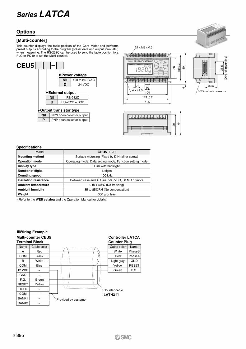
Provided by customer
Counter cable
LATH3-
BCD output connector
33.5
59
64
35.5
(DIN
rai
l mou
ntin
g)
MULTI COUNTER:CEU5 A COM COM COMB DC12V GND F.G. R.S. HOLD BANK1 BANK2
COM S.STOPOUT1OUT2OUT3OUT4OUT5AC100~240V
COUNT PRESET FUNC.
SD SGRD RS-232C
UP
LEFT RIGHT
DOWN
SEL. SETMODE
24 x M3 x 0.5
4 x ø4.5104
113±0.2
125
107
56
68±0
.2
804
Options
Multi-counter CEU5 Terminal Block
Controller LATCA Counter Plug
[Multi-counter]
CEU5Power voltage
External output
Output transistor type
Specifications
Wiring Example
∗ Refer to the WEB catalog and the Operation Manual for details.
This counter displays the table position of the Card Motor and performs preset outputs according to the program (preset data and output form, etc.) when measuring. The RS-232C can be used to send the table position to a PLC or PC or to set the Multi-counter.
Nil 100 to 240 VAC
D 24 VDC
Nil RS-232C
B RS-232C + BCD
Model CEU5-Mounting method Surface mounting (Fixed by DIN rail or screw)
Operation mode Operating mode, Data setting mode, Function setting mode
Display type LCD with backlight
Number of digits 6 digits
Counting speed 100 kHz
Insulation resistance Between case and AC line: 500 VDC, 50 MΩ or more
Ambient temperature 0 to + 50°C (No freezing)
Ambient humidity 35 to 85%RH (No condensation)
Weight 350 g or less
Nil NPN open collector output
P PNP open collector output
Cable color Name
White PhaseB
Red PhaseA
Light gray GND
Yellow RESET
Green F.G.
Name Cable color
A Red
COM Black
B White
COM Blue
12 VDC −
GND −
F.G. Green
RESET Yellow
HOLD −
COM −
BANK1 −
BANK2 −
895
Series LATCA
A

PCController
wCommunication cable
eUSB cable
qController setting software
LATC-W2
[Controller setting kit][For controller LATCA]
qController setting software (CD-ROM) LATC-W2-SwCommunication cable LEC-W2-CeUSB cable LEC-W2-U
Contents
Function
Hardware Requirements
Controller setting kit(Japanese and English are available.)
v Status display for parallel input signals and manual output of parallel output signals
v Entering of driven actuatorv Select input type (Step data input type/Pulse input type)v Setting of the step data operating conditionsv Jog, constant speed and distance movements and test
operationv Monitoring of operation status (parallel input/output
signals, position, speed and thrust)
OS IBM PC/AT compatible machine running Windows®8.1 (32-bit), Windows®8.1 (64-bit), Windows®7 (32-bit) and Windows®7 (64-bit).
Communication interface USB 1.1 or USB 2.0 portsDisplay XGA (1024 x 768)∗ Windows®7 and Windows®8.1 are registered trademarks of Microsoft
Corporation in the United States.∗ Refer to SMC website for version upgrade information, http://www.
smcworld.com
Options
896
Controller Series LATCA
LE
FS
LE
FB
LE
LL
EJS
LE
JBL
EM
LE
YL
EY
GL
ES
LE
SH
LE
PY
LE
PS
LE
RL
EH
LEY-
X511
-LEF
S11
-LEJ
S25
A-
LEC
YMLE
CYU
LECS
S-T
LA
T3
Moto
rless
LEC
S
LE
C
A

Stopper
Card Motor rail (Bottom)
Series LAT3Specific Product Precautions 1Be sure to read this before handling. Refer to page 906 for Safety Instructions. For Electric Actuator Precautions, refer to pages 907 to 912, or “Handling Precautions for SMC Products” and the Operation Manual on SMC website, http://www.smcworld.com
Design/Selection
Warning1. Consider possible movements of the actuator in the
event of an emergency stop, alarm or power failure.If power is not supplied to the product due to an emergency stop or if the SVON signal is turned OFF, in the event of an alarm (when temperature of the Card Motor exceeds 70°C) or at power failure, the table will not be held in place and may be moved by external forces. Design the Card Motor application so that people and equipment will not be injured or damaged by the table movement.
Caution1. Do not apply a load outside the specifications.
The Card Motor should be fitted for the application based on the maximum work load and allowable moments. If the product is used outside the specifications, the excess load applied to the guide will lead to play in the guide, decrease in accuracy and the life span of the product will be shortened.
2. Do not use the product in applications where exces-sive external force or impact is applied to it.Otherwise, a failure or malfunction can result.
3. The Card Motor is equipped with a stopper to prevent the table from coming off and to be resistant to light impacts generated by returning to origin or during transportation. Thus, excessive external force or impact may damage the product, so please install a separate external stopper if the operat-ing conditions require.
4. Strong magnet The Card Motor contains a strong rare earth magnet, whose magnetic field may affect the workpiece. Mount the workpiece away from the Card Motor far enough to prevent the magnetic field from affecting the workpiece.
5. In pushing operation, use thrust setting values within the allowable limits.Otherwise, it may cause overheating of the workpiece or the mounting surface.
6. The flatness of the mounting surface of the table and rail must be 0.02 mm or less.Unevenness of a workpiece the Card Motor is mounted to or of the base the Card Motor is mounted onto, can cause play in the guide and an increase in the sliding resistance.
7. SMC products are not intended for use as instruments for legal metrology.Measurement instruments that SMC manufactures or sells have not been qualified by type approval tests relevant to the metrology (measurement) laws of each country. Therefore, SMC products cannot be used for business or certification ordained by the metrology (measurement) laws of each country.
Handling
Warning1. Do not touch the product when it is energized or for a
few minutes after it has been de-energized.The surface temperature of the Card Motor can increase up to approximately 70°C depending on the operating conditions. Energizing alone may also cause the temperature to increase. Do not touch the Card Motor during operation or when energized to prevent burns or other injuries.
Caution1. Strong magnet
The Card Motor contains a strong rare earth magnet. If a magnetic card is brought close to the Card Motor, the card data may get distorted or lost. Do not bring items, which are sensitive to or affected by magnetism close to the product.
2. Do not operate the Card Motor continuously with an allowable set thrust or more at 100% of duty ratio.The Card Motor may overheat due to the heat generated by the Card Motor itself, and a temperature error or malfunction may occur.
3. Do not hit the stroke ends during operation, except during return to origin and in pushing operation.Otherwise, a failure can result.
4. For pushing operations, set the target position at least 1 mm away from the position where the pushing tool comes into contact with the workpiece.Otherwise, the table may hit the workpiece at a speed exceeding the specified pushing speed.
5. The table and the guide rail are made of special stain-less steel, but can rust in an environment where drop-lets of water adhere to it.
6. Do not dent, scratch or cause other damage to the steel ball rolling surface of the table and the rail.Otherwise, it will result in play or increased sliding friction.
7. Positioning accuracy, thrust and measurement accu-racy may vary after the Card Motor or the work load have been mounted, depending on the mounting conditions and environment.Calibrate them according to the actual application.
8. Consider mounting a bumper on the pushing surface.If impact to the Card Motor should be avoided during pushing operation, we recommend an elastic bumper is attached on the pushing surface.
897
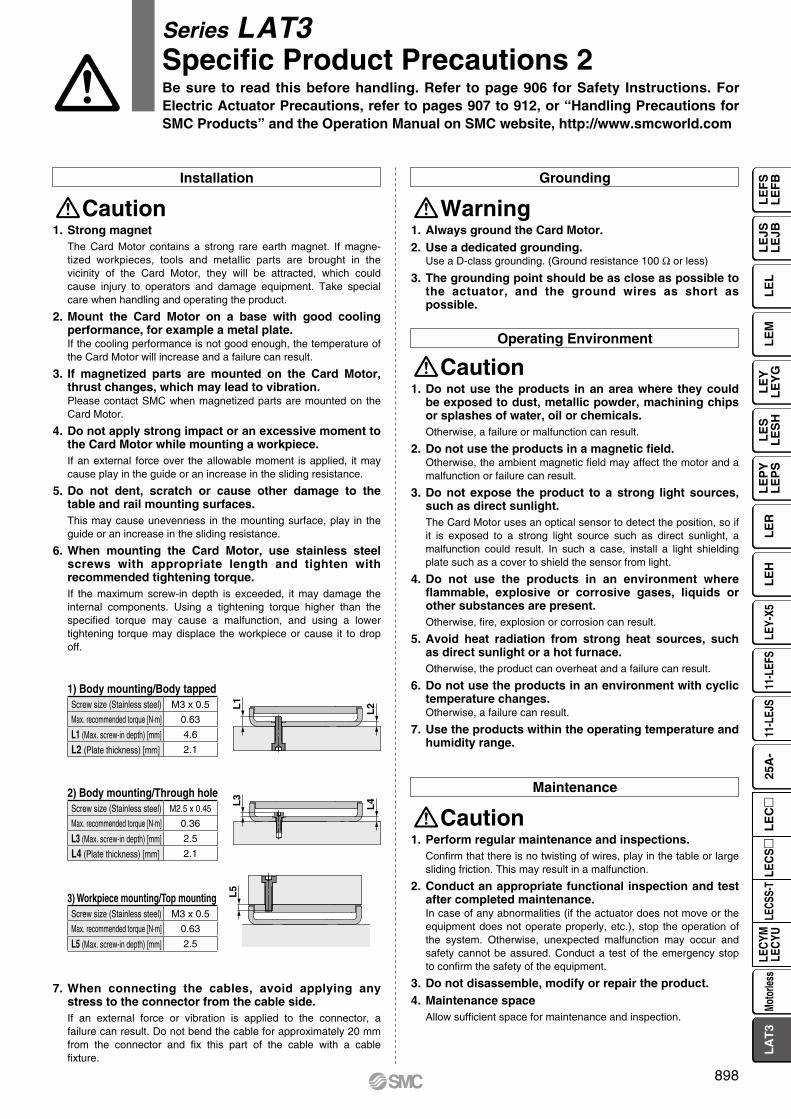
L1
L2
L4L3
L5
1) Body mounting/Body tapped
2) Body mounting/Through hole
3) Workpiece mounting/Top mounting
Operating Environment
Caution1. Do not use the products in an area where they could
be exposed to dust, metallic powder, machining chips or splashes of water, oil or chemicals.Otherwise, a failure or malfunction can result.
2. Do not use the products in a magnetic field.Otherwise, the ambient magnetic field may affect the motor and a malfunction or failure can result.
3. Do not expose the product to a strong light sources, such as direct sunlight.The Card Motor uses an optical sensor to detect the position, so if it is exposed to a strong light source such as direct sunlight, a malfunction could result. In such a case, install a light shielding plate such as a cover to shield the sensor from light.
4. Do not use the products in an environment where flammable, explosive or corrosive gases, liquids or other substances are present.Otherwise, fire, explosion or corrosion can result.
5. Avoid heat radiation from strong heat sources, such as direct sunlight or a hot furnace.Otherwise, the product can overheat and a failure can result.
6. Do not use the products in an environment with cyclic temperature changes.Otherwise, a failure can result.
7. Use the products within the operating temperature and humidity range.
Maintenance
Caution1. Perform regular maintenance and inspections.
Confirm that there is no twisting of wires, play in the table or large sliding friction. This may result in a malfunction.
2. Conduct an appropriate functional inspection and test after completed maintenance.In case of any abnormalities (if the actuator does not move or the equipment does not operate properly, etc.), stop the operation of the system. Otherwise, unexpected malfunction may occur and safety cannot be assured. Conduct a test of the emergency stop to confirm the safety of the equipment.
3. Do not disassemble, modify or repair the product.4. Maintenance space
Allow sufficient space for maintenance and inspection.
Grounding
Warning1. Always ground the Card Motor.2. Use a dedicated grounding.
Use a D-class grounding. (Ground resistance 100 Ω or less)
3. The grounding point should be as close as possible to the actuator, and the ground wires as short as possible.
Installation
Caution1. Strong magnet
The Card Motor contains a strong rare earth magnet. If magne-tized workpieces, tools and metallic parts are brought in the vicinity of the Card Motor, they will be attracted, which could cause injury to operators and damage equipment. Take special care when handling and operating the product.
2. Mount the Card Motor on a base with good cooling performance, for example a metal plate.If the cooling performance is not good enough, the temperature of the Card Motor will increase and a failure can result.
3. If magnetized parts are mounted on the Card Motor, thrust changes, which may lead to vibration.Please contact SMC when magnetized parts are mounted on the Card Motor.
4. Do not apply strong impact or an excessive moment to the Card Motor while mounting a workpiece.If an external force over the allowable moment is applied, it may cause play in the guide or an increase in the sliding resistance.
5. Do not dent, scratch or cause other damage to the table and rail mounting surfaces.This may cause unevenness in the mounting surface, play in the guide or an increase in the sliding resistance.
6. When mounting the Card Motor, use stainless steel screws with appropriate length and tighten with recommended tightening torque.If the maximum screw-in depth is exceeded, it may damage the internal components. Using a tightening torque higher than the specified torque may cause a malfunction, and using a lower tightening torque may displace the workpiece or cause it to drop off.
7. When connecting the cables, avoid applying any stress to the connector from the cable side.If an external force or vibration is applied to the connector, a failure can result. Do not bend the cable for approximately 20 mm from the connector and fix this part of the cable with a cable fixture.
Series LAT3Specific Product Precautions 2Be sure to read this before handling. Refer to page 906 for Safety Instructions. For Electric Actuator Precautions, refer to pages 907 to 912, or “Handling Precautions for SMC Products” and the Operation Manual on SMC website, http://www.smcworld.com
Screw size (Stainless steel) M3 x 0.5
Max. recommended torque [N·m] 0.63
L5 (Max. screw-in depth) [mm] 2.5
Screw size (Stainless steel) M2.5 x 0.45
Max. recommended torque [N·m] 0.36
L3 (Max. screw-in depth) [mm] 2.5
L4 (Plate thickness) [mm] 2.1
Screw size (Stainless steel) M3 x 0.5
Max. recommended torque [N·m] 0.63
L1 (Max. screw-in depth) [mm] 4.6
L2 (Plate thickness) [mm] 2.1
898
LE
FS
LE
FB
LE
LL
EJS
LE
JBL
EM
LE
YL
EY
GL
ES
LE
SH
LE
PY
LE
PS
LE
RL
EH
LEY-
X511
-LEF
S11
-LEJ
S25
A-
LEC
YMLE
CYU
LECS
S-T
LA
T3
Moto
rless
LEC
S
LE
C

1. When the Multi-counter is not used, attach the counter plug to the counter connector of the controller.If foreign matter such as metal fragments enters the counter connector, short-circuit may occur.
2. Be sure to perform return to origin prior to start.If the origin position is not set, the product will not operate even if the step data is performed.
3. The positioning time entered and set in the controller setting software is just a target value. It cannot be guaranteed.The operation may not have been completed even if the set position-ing time has passed. In such a case, the BUSY and INP digital output signals can be used to detect when the operation has been completed.
4. Set the “Load Mass” value in the controller setting software according to the approximate weight of jigs or workpieces mounted on the Card Motor.If the “Load Mass” value in the controller setting software and the weight of the work load are different, the product may vibrate or the positioning accuracy may be reduced.
5. When the load mounted on the Card Motor is small (such as 100 g or less) and the Card Motor has stopped at a target position, depending on the operating conditions the Card Motor may continuously hunt for the target position (vibrate) within the positioning accuracy range.Please contact an SMC sales representative for how to improve it.
6. BUSY signalThe BUSY signal turns ON when the Card Motor begins to operate, and it turns OFF when the operating speed reaches 2 mm/s or less. However, when the Card Motor operates at a slower speed than 5 mm/s, the BUSY signal may not turn ON at all.
7. INP output signal (OUT0)Both in positioning operation and pushing operation, the INP signal will turn ON when the table has reached within the INP output range of the target position.In pushing operation, if the table exceeds the target position and moves outside the INP output range, the INP signal will turn OFF again.
Design/Selection Handling
Warning1. Use the specified voltage.
If the applied voltage is higher than the specified voltage, malfunc-tion and damage to the controller may result. If the applied voltage is lower than the specified voltage, there is a possibility that the load cannot be moved due to internal voltage drop. Check the operating voltage prior to start. Also, confirm that the operating voltage does not drop below the specified voltage during operation.If the current is too low, the Card Motor may not be able to gener-ate the maximum force or cause a malfunction.
2. Do not use the products outside the specifications.Otherwise, fire, malfunction or damage to the product can result. Check the specifications prior to use.
3. Install an emergency stop circuit.Install an emergency stop outside the enclosure in easy reach to the operator so that the operator can stop the system operation immediately and intercept the power supply.
4. To prevent danger and damage due to a breakdown or malfunction of these products, which may occur at a certain probability, a backup system should be arranged in advance by using a multiple-layered struc-ture or by making a fail-safe equipment design, etc.
5. If there is a risk of fire or personal injury due to abnor-mal heat generation, sparking, smoke generated by the product, etc., cut off the power supply from this prod-uct and the system immediately.
Handling
Warning1. Never touch the inside of the controller and its periph-
eral devices.Otherwise, electric shock or failure can result.
2. Do not operate or set up this equipment with wet hands.Otherwise, electric shock can result.
3. Do not use a product that is damaged or missing any components.Electric shock, fire or injury can result.
4. Do not connect the controller to other devices than the Card Motor.Otherwise, it may cause damage to the controller or to the other equipment.
5. Be careful not to touch, get caught or hit by the work-piece while the Card Motor is moving.An injury can result.
6. Do not connect the power supply or power up the product until it is confirmed that the workpiece can be moved safely within the area that can be reached by the workpiece.Otherwise, the movement of the workpiece may cause an accident.
7. Do not touch the product when it is energized and for some time after the power has been disconnected, as it is very hot.Otherwise, it may cause burns due to the high temperature.
8. Check the voltage using a tester at least 5 minutes after power-off when performing installation, wiring and maintenance.Otherwise, electric shock, fire or injury can result.
9. Static electricity may cause a malfunction or damage the controller. Do not touch the controller while power is supplied to it.Take sufficient safety measures to eliminate static electricity when it is necessary to touch the controller for maintenance.
Caution
Output range of the INP signal (OUT0)
Mounting
Warning1. Install the controller and its peripheral devices on
fireproof material.Direct installation on or near flammable material may cause fire.
2. Do not install these products in a place subject to vibration and impact.Otherwise, a malfunction or failure can result.
3. Do not mount the controller and its peripheral devices on the same base together with a large-sized electromagnetic contactor or no-fuse breaker that generate vibration. Mount them on different base plates, or keep the controller and its peripheral devices away from such vibration supplies.Otherwise, a malfunction can result.
4. Install the controller and its peripheral devices on a flat surface.If the mounting surface is not flat or uneven, excessive force may be applied to the housing and other parts resulting in a malfunction.
Power Supply
Warning1. Use a power supply with low noise between lines and
between power and ground.In cases where noise is high, use an isolation transformer.
2. The power supplies should be separated between the controller power and the I/O signal power, and both power supplies must not be of “inrush current limited” type.If the power supply is of “inrush current limited” type, a voltage drop may occur during the acceleration or deceleration of the actuator.
Series LAT3Controller and Peripheral Devices/Specific Product Precautions 1Be sure to read this before handling. Refer to page 906 for Safety Instructions. For Electric Actuator Precautions, refer to pages 907 to 912, or “Handling Precautions for SMC Products” and the Operation Manual on SMC website, http://www.smcworld.com
Model Output range (mm)LAT3F- ±0.05LAT3- ±0.3
899

3. Take appropriate measures to prevent surges from lightning. Ground the surge absorber for lightning separately from the grounding of the controller and its peripheral devices.
4. Use the UL-certified products listed below as direct current power supplies.(1) Limited voltage current circuit in accordance with UL 508.
A circuit in which power is supplied by secondary coil of an insulated transformer that meets the following conditions· Maximum voltage (No load): 30 Vrms (42.4 V peak) or less· Maximum current : q 8 A or less (including short circuit)
w Limited by a circuit protector (such as a fuse) with the following ratings
(2) Circuit (of class 2) which is of maximum 30 Vrms (42.4 V peak) or less, with UL 1310 class 2 power supply unit or UL 1585 class 2 transformer.
Grounding
Maintenance
Warning
Warning
1. Make sure the product is grounded to ensure the noise tolerance of the controller.Otherwise, it may cause a malfunction, damage, electric shock or fire. Do not share the earth with devices or equipment that gener-ates a strong electromagnetic noise.
2. Use a dedicated grounding.Use a D-class grounding. (Ground resistance 100 Ω or less)
3. The grounding point should be as close as possible to the controller, and the ground wires as short as possible.
4. In the unlikely event that malfunction is caused by the ground, it may be disconnected. 1. Perform maintenance checks periodically.
Confirm wiring and screws are not loose. Loose screws or wires may cause unexpected malfunction.
2. Conduct an appropriate functional inspection and test after completed maintenance.In case of any abnormalities (if the actuator does not move or the equipment does not operate properly, etc.), stop the operation of the system. Otherwise, unexpected malfunction may occur and safety cannot be assured. Conduct a test of the emergency stop to confirm the safety of the equipment.
3. Do not disassemble, modify or repair the controller or its peripheral devices.
4. Do not put anything conductive or flammable inside the controller.Otherwise, fire can result.
5. Do not conduct an insulation resistance test or insula-tion withstand voltage test.
Wiring
Warning1. Preparation for wiring
Turn the power supply off before wiring or plugging and unplug-ging of connectors. Mount a protective cover on the terminal block after the wires have been connected.
2. Do not route the digital I/O signal and power cables together.Malfunctions stemming from noise may occur if the signal line and output lines are routed together.
3. Confirm proper wiring before turning the power on.Incorrect wiring will lead to malfunction or may damage the controller or its peripheral devices. Confirm that there is no mis-wiring before turning the power on.
4. Reserve enough space for the routing of the cablesIf the cables are forced into unreasonable positions, it may damage the cables and connectors, which may lead to miscon-nection and result in a malfunction. Avoid bending the cables in sharp angles close to the connectors or where they enter the product. Fix the cable as close as possible to the connectors so that mechanical stress cannot be applied to the connectors.
Operating Environment
Caution1. Do not use the products in an area where they could
be exposed to dust, metallic powder, machining chips or splashes of water, oil or chemicals.Otherwise, a failure or malfunction can result.
2. Do not use the products in a magnetic field.Otherwise, a malfunction or failure can result.
3. Do not use the products in an environment where flammable, explosive or corrosive gases, liquids or other substances are present.Otherwise, fire, explosion or corrosion can result.
4. Avoid heat radiation from strong heat sources, such as direct sunlight or a hot furnace.Otherwise, it will cause a failure to the controller or its peripheral devices.
5. Do not use the products in an environment with cyclic temperature changes.Otherwise, it will cause a failure to the controller or its peripheral devices.
6. Do not use the products in an environment where surges are generated.Devices (solenoid type lifters, high frequency induction furnaces, motors, etc.) that generate a large amount of surge around the product may lead to deterioration or damage to the internal circuits of the products. Avoid supplies of surge generation and crossed lines.
7. The Card Motor and the controller are not immune to lightning strikes.
8. Do not install these products in a place subject to vibration and impact.Otherwise, a malfunction or failure can result.
Caution1. Reserve sufficient space for maintenance.
Design the system so that it allows required space for mainte-nance.
Power Supply
Warning
Series LAT3Controller and Peripheral Devices/Specific Product Precautions 2Be sure to read this before handling. Refer to page 906 for Safety Instructions. For Electric Actuator Precautions, refer to pages 907 to 912, or “Handling Precautions for SMC Products” and the Operation Manual on SMC website, http://www.smcworld.com
Voltage without load (V peak) Maximum current rating
0 to 20 [V] 5.0
Over 20 [V] up to 30 [V]100
Peak voltage
900
LE
FS
LE
FB
LE
LL
EJS
LE
JBL
EM
LE
YL
EY
GL
ES
LE
SH
LE
PY
LE
PS
LE
RL
EH
LEY-
X511
-LEF
S11
-LEJ
S25
A-
LEC
YMLE
CYU
LECS
S-T
LA
T3
Moto
rless
LEC
S
LE
C