Embed Size (px)
Citation preview
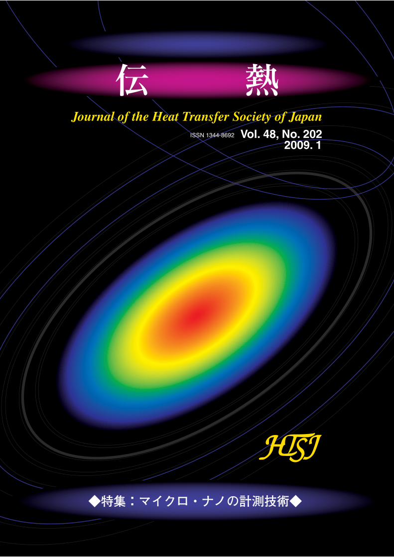
Vol. 48, No. 2022009. 1
◆特集:マイクロ・ナノの計測技術◆

2009 1 J. HTSJ, Vol. 48, No. 202
Anode Microstructure of Solid Oxide Fuel Cell
Naoki SHIKAZONO (The University of Tokyo)[email protected]
SOFC YSZNi / /
SEM-EDX 2 3NiO YSZ
3
SOFC
AGC
http://www.htsj.or.jp/heat-page.html
SEM-EDX SEM-EDX
Ni YSZ Pore Ni YSZ Pore
SEM-EDX SEM-EDX
Ni YSZ Pore Ni YSZ Pore
Vol.48 2009
No.202 January
················································································ ··············1MEMS····································································· ··············8MEMS······························································· ············ 14
························································ ············ 20
····································································· ············ 26
2008························································· ············ 31
heat-pageSOFC
··················································································· ······
······································································································ 37
················································· 3846 ······································································ 40
········································································································ 45····································································································· 50

Vol. 48 No. 202 January 2009
CONTENTS
Special IssueNano-meter, nano-gram, nano-watto in thermal measurement
Osamu NAKABEPPU (Meiji University) ·····················································································1
Boiling on MEMS heat transfer surfaces
Manabu TANGE (AIST) ··············································································································8
Micro Thermophysical Properties Sensor using Optical MEMS
Yoshihiro TAGUCHI, Yuji NAGASAKA (Keio University) ························································14
Measuring Thermal Property of Nano Materials
Koji TAKAHASHI (Kyushu University), Motoo FUJII (AIST) ···················································20
Project QDevelopment of a Pump-less Water Cooling System
Shigetoshi IPPOUSHI (Mitsubishi Electric co. Ltd.) ···································································26
ReportReport on ‘Kids Energy Symposium, 2008’
Kazuyoshi NAKABE (Chair of the Kids Energy Symp. Committee, Kyoto University) ···············31
Opening-page Gravure: heat-pageAnode Microstructure of Solid Oxide Fuel Cell
Naoki SHIKAZONO (The University of Tokyo) ······················································· Opening Page
Calendar ·······················································································································································37
Announcements ··········································································································································38
2009 1 - 1 - J. HTSJ, Vol. 48, No. 202
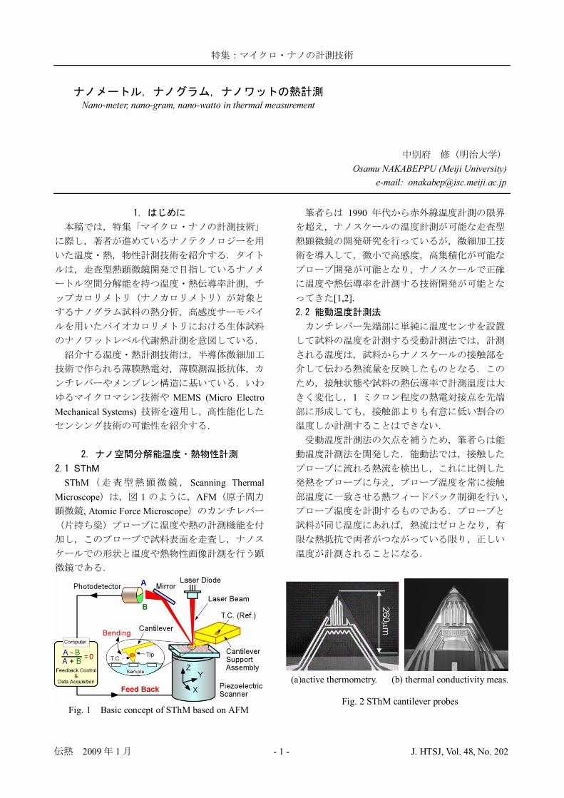
MEMS (Micro Electro Mechanical Systems)
SThMSThM Scanning Thermal
Microscope 1 AFM, Atomic Force Microscope
Fig. 1 Basic concept of SThM based on AFM
1990
[1,2]
1
(a)active thermometry. (b) thermal conductivity meas.
Fig. 2 SThM cantilever probes
Nano-meter, nano-gram, nano-watto in thermal measurement
Osamu NAKABEPPU (Meiji University)e-mail: [email protected]
2009 1 - 2 - J. HTSJ, Vol. 48, No. 202
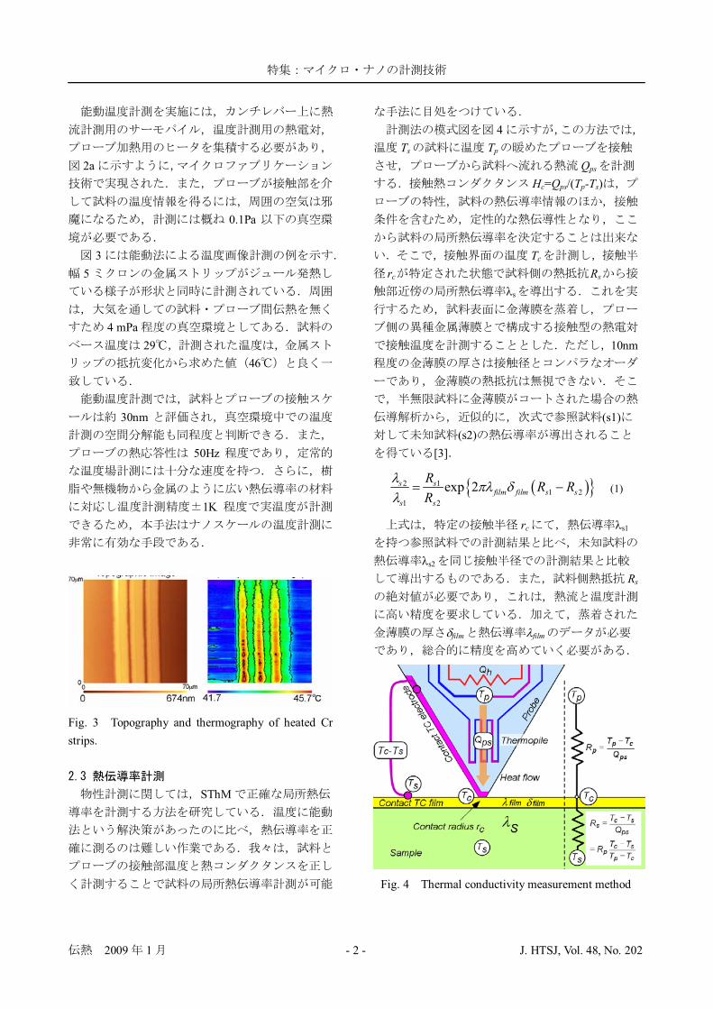
2a
0.1Pa
35
4 mPa29
46
30nm
50Hz
1K
Fig. 3 Topography and thermography of heated Crstrips.
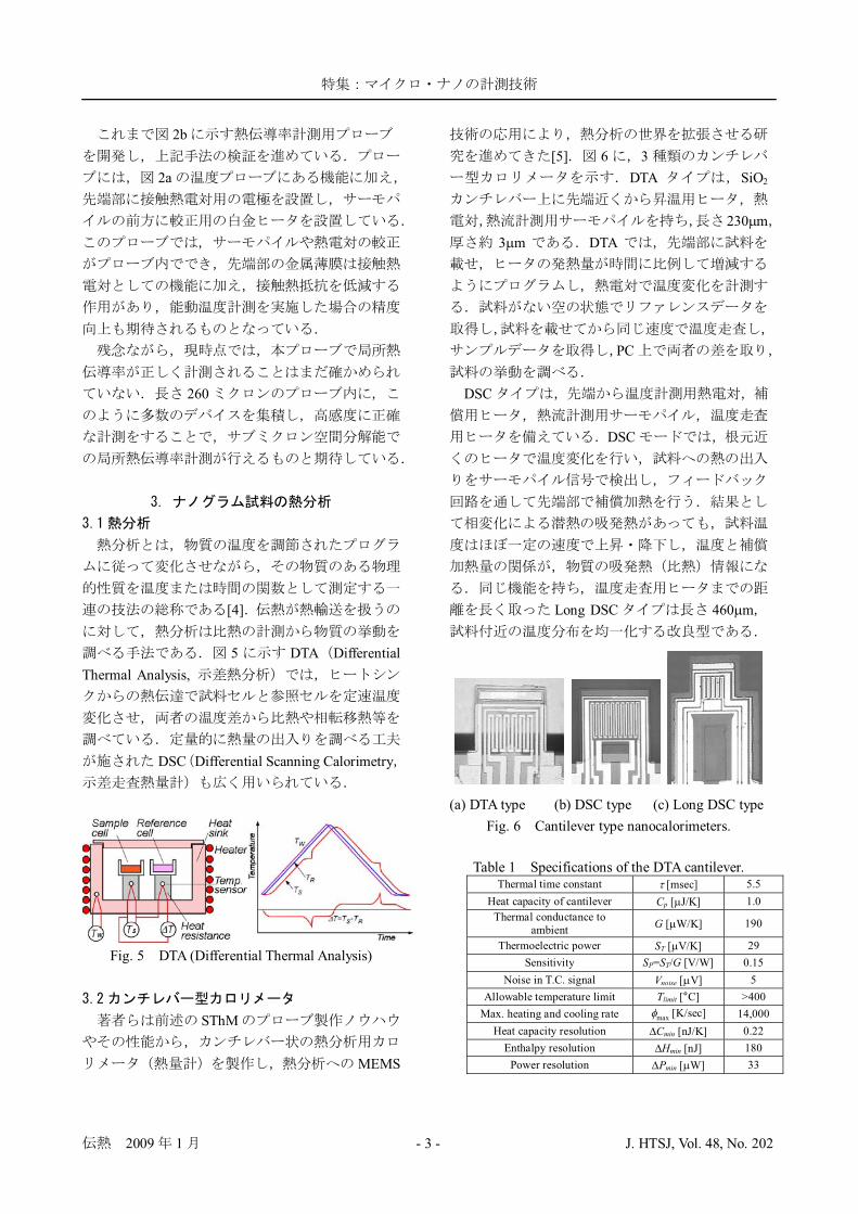
SThM
4Ts Tp
QpsHc=Qps/(Tp-Ts)
Tcrc Rs
s
10nm
(s1)(s2)
[3]
2 11 2
1 2
exp 2s sfilm film s s
s s
R R RR
(1)
rc s1
s2
Rs
film film
Fig. 4 Thermal conductivity measurement method
2009 1 - 3 - J. HTSJ, Vol. 48, No. 202
2b
2a
260
[4]
5 DTA DifferentialThermal Analysis,
DSC Differential Scanning Calorimetry
Fig. 5 DTA (Differential Thermal Analysis)
SThM
MEMS
[5] 6 3DTA SiO2
230 m3 m DTA
PC
DSC
DSC
Long DSC 460 m
(a) DTA type (b) DSC type (c) Long DSC typeFig. 6 Cantilever type nanocalorimeters.
Table 1 Specifications of the DTA cantilever.Thermal time constant [msec] 5.5
Heat capacity of cantilever Cp [ J/K] 1.0Thermal conductance to
ambient G [ W/K] 190
Thermoelectric power ST [ V/K] 29Sensitivity SP=ST/G [V/W] 0.15
Noise in T.C. signal Vnoise [ V] 5Allowable temperature limit Tlimit [°C] >400
Max. heating and cooling rate max [K/sec] 14,000Heat capacity resolution Cmin [nJ/K] 0.22
Enthalpy resolution Hmin [nJ] 180Power resolution Pmin [ W] 33
2009 1 - 4 - J. HTSJ, Vol. 48, No. 202
DTATable 1
Cmin Hminmax
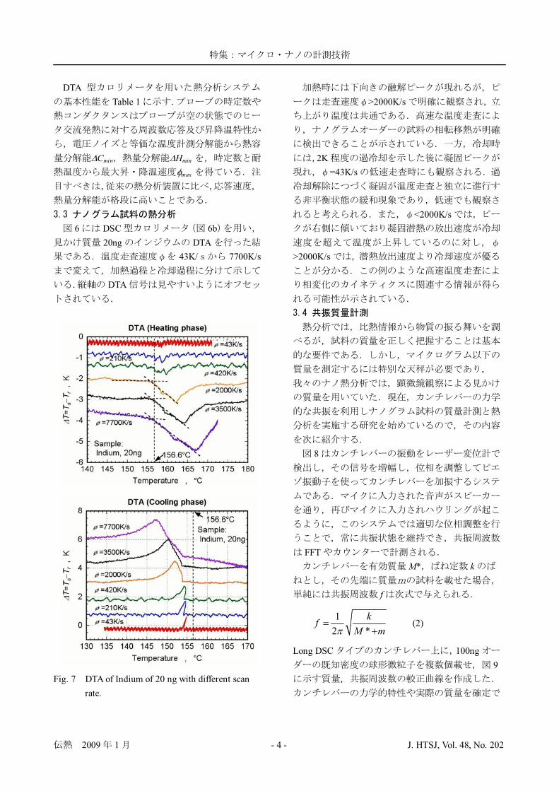
6 DSC 6b20ng DTA
43K/ 7700K/s
DTA
Fig. 7 DTA of Indium of 20 ng with different scanrate.
>2000K/s
2K=43K/s
<2000K/s
>2000K/s
8
FFTM* k
f
12 *
kfM m
(2)
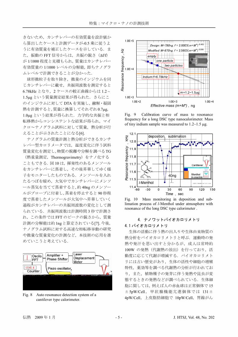
Long DSC 100ng9
2009 1 - 5 - J. HTSJ, Vol. 48, No. 202
-0.5
FFT f/f1/1000
1/1000
6.78kHz 2 1.2 ~1.5 g
DTA0.7 g
1.0 g
[6]
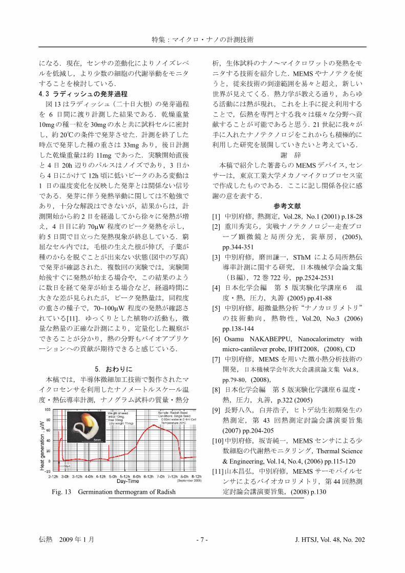
TGThermogravimetry
10
40ng90
3FFT1ng [7]
Fig. 8 Auto resonance detection system of acantilever type calorimeter.
Effective mass (m+M*) , ng
Resonancefrequency,Hz
m=1.2~1.5 g
Indium:f=6.78kHz
two particlesone particle
empty
Fig. 9 Calibration curve of mass to resonancefrequency for a long DSC type nanocalorimeter. Massof tiny indium sample was measured to 1.2~1.5 g.
Fig. 10 Mass monitoring in deposition and sub-limation process of l-Menthol under atmosphere withresonance of the long DSC type calorimeter .
100W
155pW/Cell 131
4pW/Cell 10pW/Cell

2009 1 - 6 - J. HTSJ, Vol. 48, No. 202
40~49pW/Cell 20 3pW/Cell0.067 0.01pW/cell
[8]
100nW 100
[9]MEMS
MEMS
[10]11
350
2.2 V/ W
3
Fig. 11 Thermopile sensor and measurement principle
1Hz40dB
400nW
123wt%
0.1mlM-Green Yeast and Mold Broth 0.05ml
301
8
1 280
80~12010
10,000300
400nW 10,0001,000,000
Yeast Grow th w ith MEMS TP Sensor
0.01
0.1
1
10
100
1000
0 5 10 15 20 25 30 35 40Time , h
HeatGeneration
,W
Fig. 12 Growth thermogram of Yeast.
2009 1 - 7 - J. HTSJ, Vol. 48, No. 202
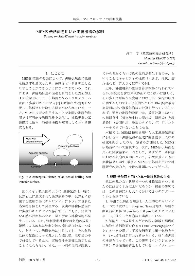
136
10mg 30mg20
33mg11mg
4 20h 34 12h
1
24 70 W
5
70~100 W[11]
Fig. 13 Germination thermogram of Radish
MEMS
21
MEMS
[1] Vol.28 No.1 (2001) p.18-28[2]
(2005),pp.344-351
[3] SThM
72 722 pp.2524-2531[4] 5
(2005) pp.41-88[5]
, Vol.20, No.3 (2006)pp.138-144
[6] Osamu NAKABEPPU, Nanocalorimetry withmicro-cantilever probe, IFHT2008 (2008), CD
[7] MEMSVol.8
pp.79-80 (2008)[8] 5
p.322 (2005)[9]
43(2007) pp.204-205
[10] MEMSThermal Science
& Engineering, Vol.14, No.4, (2006) pp.115-120[11] MEMS
44(2008) p.130
2009 1 - 8 - J. HTSJ, Vol. 48, No. 202
MEMS
[1][2] [3]
MEMS
Fig. 1: A conceptual sketch of an actual boiling heattransfer surface.
1
[4]
[5] Dhir[6]
MEMS
MEMSMEMS
MEMS
2
1Shoji and Takagi[7]
50 m 100 m
2Li and Peterson[8]
MEMSBoiling on MEMS heat transfer surfaces
Manabu TANGE (AIST)e-mail: [email protected]
Flow with
external means
Preceding bubbles
Adjacent bubbles
Cavities
2009 1 - 9 - J. HTSJ, Vol. 48, No. 202
Iida [9]
12
Nakabeppu and Wakasugi[10]
Pt [11][12]
[13] [14]Nakabeppu and
Wakasugi[10] MEMSMEMS
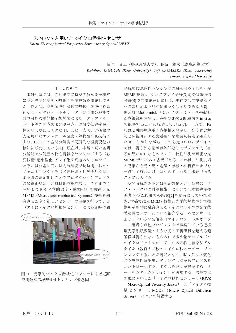
[15]3.1 MEMS
Fig. 2: MEMS heat transfer surface.
2 MEMS MEMS0.5 mm 20 mm
3
1 28 mm
2 2
2 Ni
SiO2
3 2
50 m 7Ni Cr
10 m
Fig. 3: Test section with MEMS heat transfer surface.

2009 1 - 10 - J. HTSJ, Vol. 48, No. 202
MEMS 3PEEK
3.2
Fig. 4: Temperature signal of a single bubblegeneration test; Tsub = 30 K.
Fig. 5: Bubble growth and temperature signal.
4 t=0
5
5 a-b
[16]
12 K2.7 m
4.1
[17]
Microbubble Emission Boiling, MEB
Zvirin [18]
Inada [19] MEB
Kumagai [20]MEB
Suzuki [21]MEB
MEB
[22]
MEB

2009 1 - 11 - J. HTSJ, Vol. 48, No. 202
4.2
Fig. 6: Bubbling pattern map; Tsub = 50 K.
3.1 MEMS
650 K
4
Oscillation
Kuzma-Kichta [23]
No Oscillation
Single Bubble
Oscillation
730 K
Fission 2 MW/m2
135 m SingleBubble 8
9[24]
Fission
MEB
Fig. 7: Successive snapshots of single bubble pattern; q = 1.0 MW/m2, and Tsub = 30 K, tb = 75 ms.
Fig. 8: Successive snapshots of bubble fission on a MEMS heat transfer surface; t' denotes interval from thenucleation; q = MW/m2, Tsub = 50 K, tb = 47.2 ms.

2009 1 - 12 - J. HTSJ, Vol. 48, No. 202
MEMS
MEMS
MEMS
MEMSMEMS
MEMS
16
11038
MEMS
[1] Webb, R. L., Principles of enhanced heat transfer,John Wiley & Sons, Inc., (1994).
[2] A. Ko ar and Yoav Peles, Boiling heat transfer inrectangular microchannels with reentrant cavities,Int. J. Heat Mass Transfer, 48, (2005), pp.4867-4886.
[3] Honda, H., Takamatsu, H., and Wei, J.J.,Enhanced boiling of FC-72 on silicon chips withmicro-pin-fins and submicron-scale roughness,ASME Journal of Heat Transfer, 124, (2002), pp.383–390.
[4] Han, C., and Gri th, P., “The mechanism of heattransfer in nucleate boiling — Part I”, Int. J. ofHeat Mass Transfer, 8, (1965), pp. 887–904.
[5] Son, G., Dhir, V. K., and Ramanujapu, N.,Dynamics and heat transfer associated with asingle bubble during nucleate boiling on ahorizontal surface, ASME Journal of HeatTransfer, 121, (1999), pp. 623-631.
[6] Dhir, V. K., Mechanistic prediction of nucleate
Fig. 9: Successive snapshots of bubble fission on a heated wire at 50 s intervals; q = 2 MW/m2, and Tsub = 40 K.

2009 1 - 13 - J. HTSJ, Vol. 48, No. 202
boiling heat transfer - achievable or hopeless task?,ASME Journal of Heat Transfer, 128, (2006), pp.1-12.
[7] Shoji, M. and Takagi, Y, “Bubbling features froma single artificial cavity”, Int. J. Heat MassTransfer, 44, (2001), pp. 2763–2776.
[8] Li, J., and Peterson, G. P., “Microscaleheterogeneous boiling on smooth surfaces — frombubble nucleation to bubble dynamics”, Int. J.Heat Mass Transfer, 48, (2005), pp. 4316–4332.
[9] Iida, Y., Okuyama, K., and Sakurai, K., Boilingnucleation on a very small film heater subjected toextremely rapid heating, Int. J. Heat MassTransfer, 37, (1994), pp. 2771-2780.
[10]Nakabeppu, O., and Wakasugi, H., “Approach toheat transfer mechanism beneath single boilingbubble with MEMS sensor”, In Proc. of 13thInternational Heat Transfer Conference, (2006),BOI-43 (CD-ROM).
[11]Moghaddam, S., Kiger, K. T., Henriette, J. M.,and Ohadi, M., “Fabrication and testing of a novelmicroelectromechanical device for the study ofboiling bubble dynamics”, In Proc. of ASMEInternational Mechanical Engineering Congress,(2003), pp. 107–114.
[12]Cooper, M. G. and Lloyd, A. J. P. “Miniature thinfilm thermometers with rapid response”, J. ofScientific Instruments, 42, (1965), pp. 791–793.
[13]Zhang, L., and Shoji, M., Nucleation siteinteraction in pool boiling on the artificial surface,Int. J. of Heat Mass Transfer, 46, (2003), pp.513-522.
[14]Kenning, D. B. R., and Yan, Y., “Pool boiling heattransfer on a thin plate: features revealed by liquidcrystal thermography”, Int. J. Heat Mass Transfer,15, (1996), pp. 3117–3137.
[15]Tange, M., Takagi, S., Takemura, F., and Shoji,M., Bubble growth and fission on MEMS heattransfer surfaces under subcooled boilingconditions, Trans. of JSME B, (submitted).
[16]Carey, V. P., Liquid-vapor phase-changephenomena, Taylor & Francis, (1992).
[17]Tange, M., Yuasa, M., Takagi, S., and Shoji, M.,“Microbubble Emission Boiling in aMicrochannel and Minichannel”, Thermal Scienceand Engineering, 12-6, (2004), pp. 23–29.
[18]Zvirin, Y., Hewitt, G. F., and Kenning, D. B. R.,Experimental study of drag and heat transferduring boiling on free falling spheres, Heat andTechnology, 7-3-4, (1989), pp. 13-23.
[19] Inada, S., Miyasaka, Y., Sakumoto, S., andChandratilleke, G. R., “Liquid-solid contact statein subcooled pool transition boiling system”,ASME Journal of Heat Transfer, 108, (1986), pp.219–221.
[20]Kumagai, S., Uhara, T., Nakata, T., and Izumi, M.,Liquid-solid contact in microbubble emissionboiling through void signals, Trans. of JSME B,67, (2001), pp. 2304-2310.
[21]Suzuki K., Torikai, K., Satoh, H., Ishimaru, J.,and Tanaka, Y., “Boiling heat transfer ofsubcooled water in a horizontal rectangularchannel (observation of MEB and MEBgeneration)”, Trans. of JSME B, 65, (1999), pp.3097–3104.
[22]Shoji, M. and Yoshihara, M., Observation ofmicrobubble emission boiling, J. visualizationsociety of Japan, 11, (1991), pp. 143-148.
[23]Kuzma-Kichta, Y., Ustinov, A. K., Ustinov, A. A.,and Kholpanov, L., Investigation of interfaceoscillations during boiling, In proc. of the thirdinternational conference on transport phenomenain multiphase systems, (2002), pp. 45-52.
[24]Shoji, M., Tange, M., Watanabe, M., Kamoshida,J., Sasaki, K., “Subcooled pool boiling on aheated wire with microbubble emission”, In Proc.of EECI International Conference on Boiling HeatTransfer, (2006), paper no. 30 (CD-ROM).
2009 1 - 14 - J. HTSJ, Vol. 48, No. 202
[1]
100 nm[2]
MEMS Microelectromechanical Systems
1
MEMS [3, 4][5]
[6-8]McCormick
3 in vivo[7] Ra
2
[8] MEMS
MEMS
[2]MEMS
MOVSMicro Optical Viscosity Sensor
MODS Micro Optical DiffusionSensor
MEMSMicro Thermophysical Properties Sensor using Optical MEMS
Yoshihiro TAGUCHI (Keio University), Yuji NAGASAKA (Keio University)e-mail: [email protected]
1
2009 1 - 15 - J. HTSJ, Vol. 48, No. 202
[9]
2
Micro Optical ViscositySensor: MOVS [10, 11]
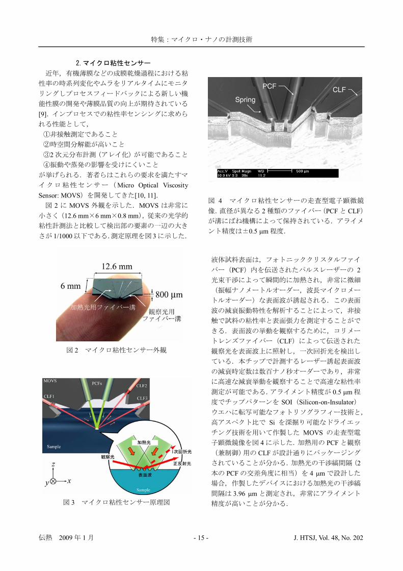
2 MOVS MOVS12.6 mm 6 mm 0.8 mm
1/1000 3
PCF 2
CLF
0.5 mSOI Silicon-on-Insulator
SiMOVS
4 PCFCLF
2PCF 4 m
3.96 m
2
3
42 PCF CLF
0.5 m

2009 1 - 16 - J. HTSJ, Vol. 48, No. 202
MOVS 10 m FWHM
MOVS
CLF1CLF3
5CLF3
PD 200 kHzPID PID
MOVS
500 Hz
6
60
PSF0.7 m
MOVS
MOVS7 Hz 13 m
0.01 wt%7 2
256
S/N 4
MOVS
5
0 10 20 30 40100
150
200
250
0
5
10
15Under controlWithout control
Time , sec
zdisplacem
ent,μm
Ref
lect
edlig
htin
tens
ity,m
V
6
0 1 2 3
0
0.02
0.04
0
0.1
Time, sS
igna
lInt
ensi
ty,m
V
Under Control
Without Control
7
2009 1 - 17 - J. HTSJ, Vol. 48, No. 202
TAS Total Analytical Systems
[12]TAS
MicroOptical Diffusion Sensor: MODS
8
9 MODSITO
a-Si:H
1 1
8
9
10
11

2009 1 - 18 - J. HTSJ, Vol. 48, No. 202
MODS ITOMODS
MEMSMODS 10
11MODS
12
13
1 m
2
14
ITO 10 Vp-p 50kHz
15
10–410–310–210–1 100 101 10210–4
10–3
10–2
Light Intensity, W/cm 2
Con
duct
ivity
,S/m
13
14
1512
2009 1 - 19 - J. HTSJ, Vol. 48, No. 202
MEMS
MEMS
24
S No. 19106004
[1] Taguchi, Y. and Nagasaka, Y., Thermal DiffusivityMeasurement of High-Conductivity Materials byDynamic Grating Radiometry, Int. J. Thermophys.,22 (2001) 289.
[2] Jigami, T., Kobayashi, M., Taguchi, Y. andNagasaka, Y., Development of nanoscaletemperature measurement technique usingnear-field fluorescence, Int. J. Thermophys., 28(2007) 968.
[3] Solgaard, O., Sandejas, F.S.A. and Bloom, D.M.,Deformable grating optical modulator, Opt. Lett.,17 (1992) 688.
[4] Hornbeck, L.J., Current Status of the DigitalMicromirror Device (DMD) for ProjectionTelevision Applications, Tech. Dig. Int. ElectronDevices Meet., (1993) 381.
[5] Bishop, D.J. et al, The Lucent LambdaRouter:MEMS Technology of the Future Here Today,IEEE Communications Magazine, 40 (2002) 75.
[6] Chong, C., Isamoto, K. and Toshiyoshi, H.,Optically Modulated MEMS Scanning Endoscope,IEEE Photo. Tech. Lett., 18 (2006) 133.
[7] McCormick, D.T. et al, A Three DimensionalReal-time MEMS based Optical Biopsy Systemfor In-vivo Clinical Imaging, Proc. 14th Int. Conf.Solid-State Sensors, Actuators and Microsystems,Lyon, (2007) 203.
[8] Ra, H., Piyawattanametha, W., Taguchi, Y., Lee,D., Mandella, M.J., Solgaard, O.,Two-dimensional MEMS scanner for dual-axesconfocal microscopy, J. Microelectromech. Syst.,16 (2007) 969.
[9] Tjong, S.C., Structure, morphology, mechanicaland thermal characteristics of the in situcomposites based on liquid crystalline plymersand thermoplastics, Mater. Sci. Eng. R Rep., 41(2003) 60.
[10]Taguchi, Y., Ebisui, A. and Nagasaka, Y.,Miniaturized optical viscosity sensor based on alaser-induced capillary wave, J. Opt. A Pure Appl.Opt, 10 (2008) 044008.
[11]Nagamachi, R., Taguchi, Y. and Nagasaka, Y.,Development of Miniaturized Optical Viscometerwith Focus Control System for in-situMeasurement, Proc. 18th Europ. Conf.Thermophys. Prop., Pau (2008).
[12]Ebisui, A., Taguchi, Y. and Nagasaka, Y.,Feasibility Study of Micro Optical DiffusionSensor based on Opto-dielectrophoreticManipulation, Proc. 18th Europ. Conf.Thermophys. Prop., Pau (2008).
2009 1 - 20 - J. HTSJ, Vol. 48, No. 202
1
IC
3 [1] [2]
[3]
10,106600W/mK
[4,5]
[6,7]
200W/mK
-
Majumdar[8] [9]
3[10]
3000W/mK[11,12]
Measuring Thermal Property of Nano Materials
Koji TAKAHASHI (Kyushu University), Motoo FUJII (AIST)e-mail: [email protected]

2009 1 - 21 - J. HTSJ, Vol. 48, No. 202
2000W/mK
[13]1
1(b)
TL
1 21
qv
021
112
vqdxxTd (1)
I Vl w
d qv =IV/(lwd) 2
ff
02
2
f
fff dx
xTd (2)
T0Tj
011
02
12111 2
22
Txl
TTlqx
qxT jvv (3)
l
L dxTxTl
T0 0
1(4)
2120
32
31
TTlqll
T jvL (5)
, RR0 (0 )
TL= R/( R0)
qf AhAf
hhff AxTA
xTAq
2
2
1
1 (6)
(3)T1 T2
21
0
2 lllTTlq
AAq jv
f
hf (7)
Sample
Hot Wire
T0
TL
Tj
T0T0
Heat Sink
Hot Wire
TL
T0T0
Heat Sink & Terminal
1 2
(a) (b)1

2009 1 - 22 - J. HTSJ, Vol. 48, No. 202
f
jff l
TTq 0 (8)
(7) (8)
0
21
0
2TTlllTTlq
AlA
j
jv
f
fhf (9)
(5)
ffvLf
vLhfhff AllAllqTlAll
qTAllAll4212
4121
224
/12/12
(10)
TL/qv
2 SiO2
Si
Ti PtTi
5nm Pt SiO2
PtBHF
SiO2
Ti PtKOH
CF4 Si
Pt
Pt
1[14]
SEM
WEBID
TEMSEM
EBID SEM
(2) Electrical beamlithography
Suspended Pt hotfilm
(5) SiO2 etching (6) Si etching
EB resist
Si(100) SiO2
(3) Physical deposition (4) Lift off
(1)EB resist coating
Pt/Ti
(2) Electrical beamlithography
Suspended Pt hotfilm
(5) SiO2 etching (6) Si etching
EB resist
Si(100) SiO2
(3) Physical deposition (4) Lift off
(1)EB resist coating
Pt/Ti
23 SiC
T SEM

2009 1 - 23 - J. HTSJ, Vol. 48, No. 202
W
3
FIB( )W Pt
10-3Pa
Pt
4 [9]4(a)
300K4(b)
SiC [15]SiC
50K340K
[16]
AFM
1Majumdar
UC
100nm
MEMS[8]MEMS
Majumdar
0.5 m
(a)
(b)4
do di

2009 1 - 24 - J. HTSJ, Vol. 48, No. 202
14 m 25 m 22 m 420 m
2
52
3
5(b)
shssb TTGTTGQ 0 (11)
Gs
Gb
[17]
[18]
[19]
[20]
MEMSUC
MembraneSample
Beam
Heat sink
Gs
Gb
Q
Q
V
A
V
A
Th Ts
T0
MembraneSample
Beam
Heat sink
Gs
Gb
Q
Q
VV
AA
VV
AA
Th Ts
T0
(a)
Th Ts T0Gs Gb
Q
Th Ts T0Gs Gb
Q
(b)5 UC MEMS
2009 1 - 25 - J. HTSJ, Vol. 48, No. 202
T
[1] Cahill, D.G., Thermal Conductivity measurementfrom 30-750K: The 3w method, Rev. Sci. Inst.,61-2 (1999) 802.
[2] Kading, O.W. et al, Thermal conduction inmetallized silicon-dioxide layers on silicon, Appl.Phys. Lett., 65 (1994) 1629.
[3] Berber, S. et al., Unusually High ThermalConductivity of Carbon Nanotubes, Phys. Rev.Lett., 84-20 (2000) 4613.
[4] ,, , 19-3 (2005) 185
[5] Lukes, J.R. and Zhong, H., Thermal conductivityof individual single-wall carbon nanotubes,ASME J. Heat Transfer, 129 (2007) 705.
[6] Hone, J. et al., Thermal conductivity ofsingle-walled carbon nanotubes, Phys. Rev. B, 59(1999) 2514.
[7] Hone, J. et al., Electrical and thermal transportproperties of magnetically aligned single wallcarbon nanotube films, App. Phys. Lett., 77-5(2000) 666.
[8] Kim, P. et al., Thermal Transport Measurementsof Individual Multiwalled Nanotubes, Phys. Rev.Lett., 87-21 (2001) 215502.
[9] Fujii, M. et al., Measuring the ThermalConductivity of a Single Carbon Nanotubes, Phys.Rev. Lett., 95 (2005) 065502.
[10]Choi, T.Y. et al., Measurement of the ThermalConductivity of Individual Carbon Nanotubes by
the Four-Point Three- Method, Nano Lett., 6-8(2006) 1589.
[11]Yu, C. et al., Thermal Conductance andThermopower of an Individual Single-WallCarbon Nanotube, Nano Lett., 5-9 (2005) 1842.
[12]Pop, E. et al., Thermal Conductance of anIndividual Single-Wall Carbon Nanotube aboveRoom Temperature, Nano Lett., 6-1 (2006) 96.
[13]Zhang, X., et al., Measurements of thermalconductivity and electrical conductivity of a singlecarbon fiber, Int. J. Thermophysics, 21-4 (2000)965.
[14]Nishijima, H. et al., Carbon nanotube tips forscanning probe microscopy: Preparation by acontrolled process and observation ofdeoxyribonucleic acid, App. Phys. Lett., 74-26(1999) 4061.
[15]Takahashi, K., et al, Thermal conductivity of SiCnanowire formed by combustion synthesis, HighTemperatures-High Pressures, 37-2 (2008) 119.
[16]Dames, C., et al., A hot-wire probe for thermalmeasurements of nanowires and nanotubes insidea transmission electron microscope, Rev. Sci. Inst.,78 (2007) 104903.
[17]Shi, L., et al., Measuring Thermal andThermoelectric Properties of One-DimensionalNanostructures Using a Microfabricated Devices,ASME J. Heat Transfer, 125 (2003) 881.
[18]Chang, C.W., et al., Nanotube Phonon WaveguidePhys. Rev. Lett., 99 (2007) 045901.
[19]Chang, C.W., et al., Solid-State Thermal Rectifier,Science 314 (2006) 1121.
[20]Hochbaum, A.I., et al., Enhanced thermoelectricperformance of rough silicon nanowires, Nature,451 (2008) 163.

Q
2009 1 - 26 - J. HTSJ, Vol. 48, No. 202
1IT IT
IT
2
240
CO2
/
2a
Development of a Pump-less Water Cooling System
Shigetoshi IPPOUSHI (Mitsubishi Electric co. Ltd.)e-mail: [email protected]

Q
2009 1 - 27 - J. HTSJ, Vol. 48, No. 202
1
2
100 110 140
100 100
Q
2009 1 - 28 - J. HTSJ, Vol. 48, No. 202
a b2
2 a
2 b
cm
Q
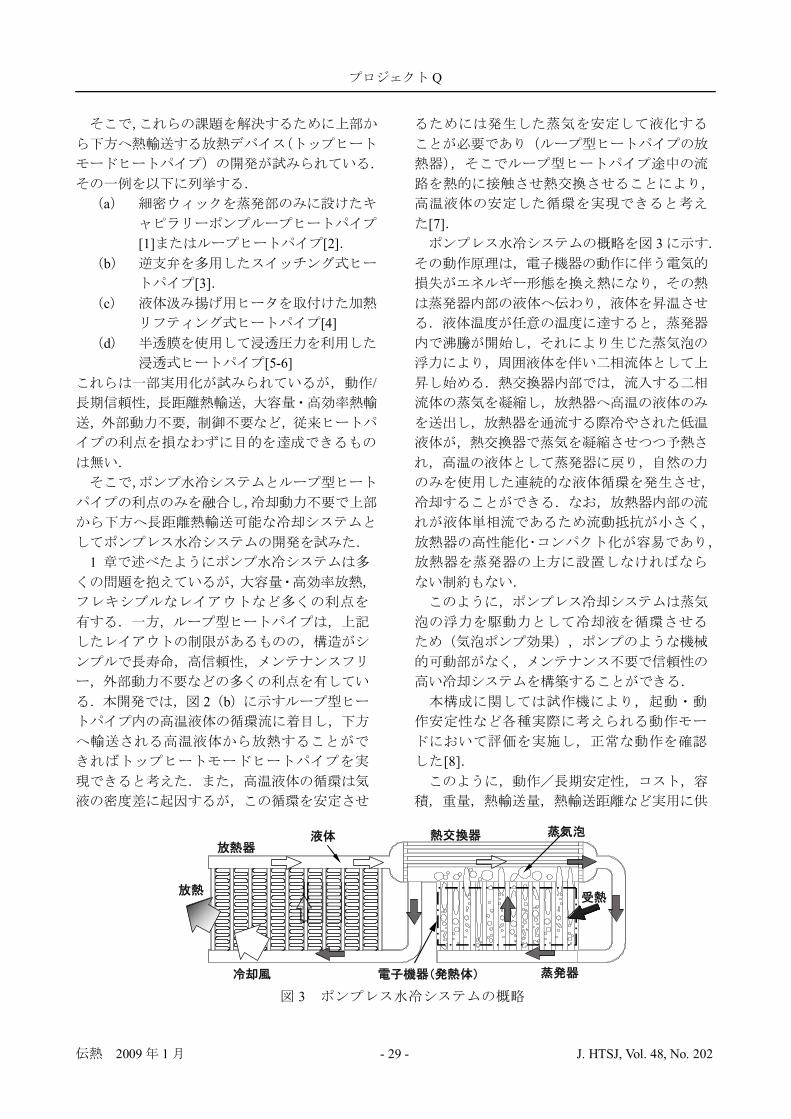
2009 1 - 29 - J. HTSJ, Vol. 48, No. 202
a
[1] [2]b
[3]c
[4]d
[5-6]/
1
2 b
[7]3
[8]
3
Q
2009 1 - 30 - J. HTSJ, Vol. 48, No. 202
/
/
/ /
10040
0
CO2
[1] Stenger, F. J., “Experimental Feasibility Study ofWater-Filled Capillary-Pumped Heat-TransferLoops”, NASA TM X-1310, (1966), 1.
[2] Maidanik, Yu. F., Pastukhov, V. G., Fershtater, Yu.G., Smirnov-Vasiliev, K. G., Chernishev, V. F. andDvirniy, V. V., “Development, Analytical andExperimental Investigation of Loop Heat Pipes”,Proc. 7th Int. Heat Pipe Conf., 2 (1988), 539.
[3] Kawabata, K., Hashimoto, N. and Kamiya, Y.,“Anti-Gravity Heat Pipe”, Proc. 5th Int. Heat PipeSymp., Melbourne, (1997), 168
[4] Chisholm, D., “The Anti-Gravity Thermosyphon”,Proc. I. Chem. E. Symp, Glasgow, Ser. No. 38(1974), F3.
[5] Baer, S. C., “Heat Pipe Condensate Return”, U. S.Patent No. 3561525, (1971).
[6] , “,
”, ,64-617, B (1998), 254.
[7] ” ”,, Vol.50, No.9(2008), P70.
[8]” ”
45514(2008)

2009 1 - 31 - J. HTSJ, Vol. 48, No. 202
2008 9 13
1
53 110 149 100
47 3
10B
1
1
Report on ‘Kids Energy Symposium, 2008’
Kazuyoshi NAKABE(Chair of the Kids Energy Symp. Committee, Kyoto University)
e-mail: [email protected]
1

2009 1 - 32 - J. HTSJ, Vol. 48, No. 202
3
3
2 10
1,000
(http://www.museum.kyoto-u.ac.jp/indexj.html)
1,000
KYO-NANO
59% 13% 10%10% 6% 2%
43% 39%18%
2 3
1
12:30~13:00
13:00~13:05
13:05~13:5513:55~14:1014:10~14:20
14:20~14:40
14:40~14:45
LNG
14:45~16:55
16:55~17:15
2009 1 - 33 - J. HTSJ, Vol. 48, No. 202
2 2
5
200
6
2 1
4 5 6
1
4 (48%) 5 (24%) 6 (15%)(13%) (72%) (28%)
20082
(59%) (13%)(10%) (10%) (6%)(2%)
3
196
LNG
4
6
1mm

2009 1 - 34 - J. HTSJ, Vol. 48, No. 202
2
30
2
3 1
2 3
7
(100%) (0%)

2009 1 - 35 - J. HTSJ, Vol. 48, No. 202
4 52
6
7
8
9-1
9-2 2
10
2009 1 - 37 - J. HTSJ, Vol. 48, No. 202
20096 2 ( )
4 ( )
46
2009.1.26 2009.3.16
Email: [email protected]://nhts2009.me.kyoto-u.ac.jp/index.html 10
1
2009
1 23( ) 2009.1.13
( )160-0016 35
5Web: http://www.jsme.or.jp/kousyu2.htm
1 29 ( )30 ( )
15th Symposium on "Microjoining and AssemblyTechnology in Electronics" 2008.9.4 2008.10.20
( ) Mate 2009101-0025
1-11TEL 03-3253-0488 FAX 03-3253-3059Email: [email protected]: http://wwwsoc.nii.ac.jp/jws/research/
micro/mate/Mate2009.html
3 4( )5( )
20092009
221-0052 5-1 YCS5F( )TEL 045-450-1831 FAX 045-441-8444Email: [email protected]
3 12( ) 2009.2.28TEL & FAX: 03-3259-0749Email: [email protected]
5 12(14( )
14 2009.1.30 2009.4.3
101-8449 3-24( )ICS
TEL 03-3219-3541 FAX 03-3292-1811Email: [email protected]
8 2(5( )
7th Annual International Energy Conversion EngineeringConference (IECEC2009)
Denver, CO, USA2008.12.7 2009.5.19
514-8507 1577
TEL & FAX: 059-231-9386Email: [email protected]: http://www.aiaa.org/content.cfm?pageid=230&lumeetingid=1894&viewcon=overview
8 7( )9( )
200928 2009.3.30 2009.6.5
2009860-8555 2-39-1
TEL/FAX 096-342-3753Email : [email protected]: http://www.mech.kumamoto-u.ac.jp
/jsmf2009/index.php
9
10
27 ( )
2 ( )
13 NURETH13 2008.10.31 2009.1.31
NURETH-13( )
TEL: 0770-37-9110Email: [email protected]: http://www.nureth13.org/
11 16 ( )
19 ( )
The 7th Pacific Symposium on Flow Visualization andImage Processing (PSFVIP-7)
Kaohsiung, Taiwan, ROC2008.10.31 2009.4.15
Dr. Tai, C.H., National Pingtung Univ. ofScience and Technology (Taiwan, ROC)Email: [email protected]: http://www.tuat.ac.jp/%7Epctfe/
1116( )
20( )
International Conference on Power Engineering-09,Kobe (ICOPE-09) 2008.12.31 2009.3.31
Ryosuke MatsumotoKansai UniversityEmail: [email protected]

2009 1 - 38 - J. HTSJ, Vol. 48, No. 202
3 2009FAX
6
1.
1 (1) (2)2
3 (a) (b) (c) (d)
10
2.4 6 FAX
6 7 CD-ROM10 4
3.
1
4FAX

2009 1 - 39 - J. HTSJ, Vol. 48, No. 202
1
2009 1 - 40 - J. HTSJ, Vol. 48, No. 202
46
46
21 6 2 6 4
http://www.icckyoto.or.jp/JR 20 5http://www.icckyoto.or.jp/jp/access/access.html
606-0001 Phone: 075-705-1234 / Fax: 075-705-1100
21 1 7 1 1921 2 24 3 1621 2 24 4 13
URL http://nhts2009.me.kyoto-u.ac.jp/
a)b)c)
1 15 10 55
12,000 14,0005,000 6,000
J-STAGECD-ROM CD-ROM
8,000
21 6 3
2009 1 - 41 - J. HTSJ, Vol. 48, No. 202
8,000 10,0004,000 5,000
250
200 250JST
1 1J-STAGE
J-STAGE 2009 4J-STAGE
CD-ROM
1 A4 22 26 60
82 MB
J-STAGE
“Thermal Science and Engineering TSE ”
TSEON TSE
2009 1 - 42 - J. HTSJ, Vol. 48, No. 202
TSE2 TSE 8
TSETSE
PDFPDF 1 3,000
PDFCD-ROM J-STAGE
J-STAGE
150mm
9 2 1 26 22 60
(1)
Guide for the manuscripts : Times New Roman 12ptThe case of MS-Word : Times New Roman 12pt
112pt
1Taro DENNETSU ( Times New Roman 10pt)
Dept. of Mech. Eng., Kyoto Univ. of Science, Kyotanabe, Kyoto 610-03211
5 English abstract ..... Times New Roman10pt, 100
1Key Words : Heat Transfer Times New Roman 9pt, 3 5
1
150mm
2009 1 - 43 - J. HTSJ, Vol. 48, No. 202
, , - , .1 2 , (B), 12-345(2006), 1234.
PDFPDF
1 J-STAGE
1ID 4 1234
2ID
0001587
111282946
ATMATM
14 14
21 ID3
E-mail Fax
46
E-mail: [email protected]: 075-753-5209

2009 1 - 44 - J. HTSJ, Vol. 48, No. 202
46
46
21 6 2 11 3 SP 80
PP
21 3 31 28
1 146
2

(HP ML )
( )
( )HP ML
1 4 1 ( )
HP ( )
HP
(
)
HP ( )ML ( ) HP ML
()
HP ()
HP
http://www.htsj.or.jp/banner.pdf
Word textHP
[email protected] [email protected]
[email protected] [email protected]
ML pdf
2009 1 - 45 - J. HTSJ, Vol. 48, No. 202

2009 1 - 46 - J. HTSJ, Vol. 48, No. 202
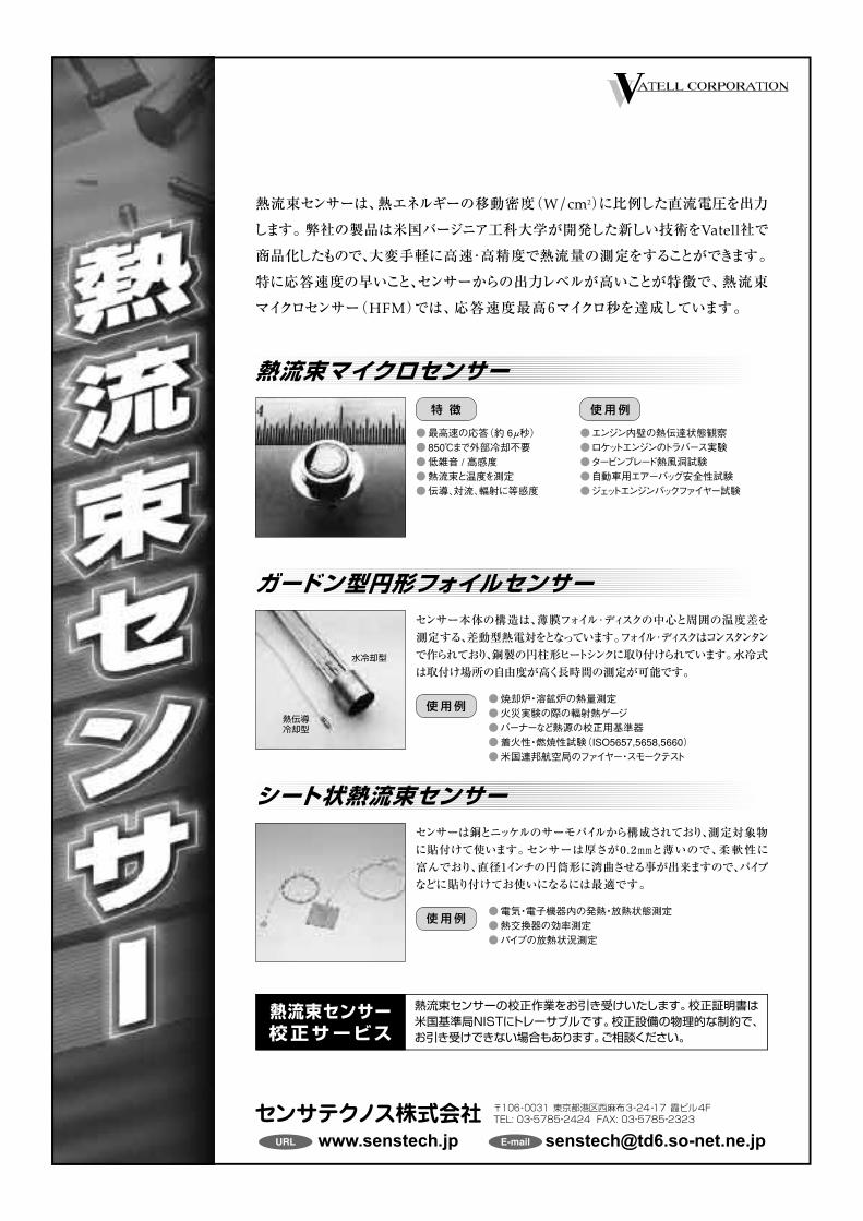
熱流束センサーは、熱エネルギーの移動密度(W/cm2)に比例した直流電圧を出力
します。弊社の製品は米国バージニア工科大学が開発した新しい技術をVatell社で
商品化したもので、大変手軽に高速・高精度で熱流量の測定をすることができます。
特に応答速度の早いこと、センサーからの出力レベルが高いことが特徴で、熱流束
マイクロセンサー(HFM)では、応答速度最高6マイクロ秒を達成しています。
URL E-mail [email protected]
〒106-0031 東京都港区西麻布3-24-17 霞ビル4FTEL: 03-5785-2424 FAX: 03-5785-2323
特 徴
●最高速の応答(約 6μ秒)●850℃まで外部冷却不要●低雑音 / 高感度●熱流束と温度を測定●伝導、対流、輻射に等感度
使用例
●エンジン内壁の熱伝達状態観察●ロケットエンジンのトラバース実験●タービンブレード熱風洞試験●自動車用エアーバッグ安全性試験●ジェットエンジンバックファイヤー試験
センサー本体の構造は、薄膜フォイル・ディスクの中心と周囲の温度差を
測定する、差動型熱電対をとなっています。フォイル・ディスクはコンスタンタン
で作られており、銅製の円柱形ヒートシンクに取り付けられています。水冷式
は取付け場所の自由度が高く長時間の測定が可能です。
使用例●焼却炉・溶鉱炉の熱量測定●火災実験の際の輻射熱ゲージ●バーナーなど熱源の校正用基準器●着火性・燃焼性試験(ISO5657,5658,5660)●米国連邦航空局のファイヤー・スモークテスト
熱流束マイクロセンサー
ガードン型円形フォイルセンサー
センサーは銅とニッケルのサーモパイルから構成されており、測定対象物
に貼付けて使います。センサーは厚さが0.2mmと薄いので、柔軟性に
富んでおり、直径1インチの円筒形に湾曲させる事が出来ますので、パイプ
などに貼り付けてお使いになるには最適です。
熱流束センサーの校正作業をお引き受けいたします。校正証明書は米国基準局NISTにトレーサブルです。校正設備の物理的な制約で、お引き受けできない場合もあります。ご相談ください。
使用例●電気・電子機器内の発熱・放熱状態測定●熱交換器の効率測定●パイプの放熱状況測定
シート状熱流束センサー
熱流束センサー校正サービス
水冷却型
熱伝導冷却型

CAPTECCAPTEC
5 5 300 300 [mm] 0.4 [mm]0.00015 [ /(W/m2)]2.7 W/mK
200 200 [ ]200 [ms]
30 [mm]
T350 [ ] 380 [ ]
5 5 50 50 [mm] 0.25 [mm]
200 250 [ ]50 [ms]
30 [mm] T
350 [ ] 380 [ ]
CAPTEC
CAPTEC URL: http://www.techno-office.com/
225-0011 3-20-8-B TEL. 045 (901) 9861 FAX. 045 (901) 9522

LaVision
Laser Imaging Solution
High-SpeedMaster System
StrainMaster
PlasmaMaster
FlameMasterEngineMaster
SprayMasterSizingMaster
FlowMasterFluidMaster
LIIRayleighRamanPIVLIFMieLaser Imaging Techniques
Email [email protected]. (03)6825-9090 FAX. (03)5371-7680URL http://www.kanomax.co.jp/fgroup.html
PIV LIF Raman Rayleigh LII
2009 1 - 50 - J. HTSJ, Vol. 48, No. 202
Heart Transfer
Takemi Chikahisa (Hokkaido University)e-mail: [email protected]
TSE
060-8628 13 8Tel: 011-706-6785 Fax: 011-706-7889 [email protected]
Note from the Editorial Board


![â Y2017 †fÛ ‰ 1 Ù]‚jÂ] ñ]‚Þ1€¦ · â Y2017 †fÛ ‰ 3 Ù]‚jÂ] ñ]‚Þ1 NIDA-E-AETIDAL DECEMBER - 2017 O¶Z óóóxxxxóóóssssZZZ»»»»ÇÇÇÇààààzzzgggzg—](https://img.pdfslide.tips/doc/110x75/5ecc18b35d36630115296589/-y2017-af-a-1-aj-a1-y2017-af-a-3-aj-a1.jpg)