Embed Size (px)
Citation preview
PART II ACTIONS AND MATERIAL STRENGTH REQUIREMENTS, CHAPTER 3 GEOTECHNICAL CONDITIONS
–207–
Chapter 3 Geotechnical Conditions
Public NoticeGeotechnical Conditions
Article 13Geotechnicalconditionsshallbeappropriatelysetintermsofthephysicalandmechanicalpropertiesofthesoilbasedontheresultsofgroundinvestigationsandsoiltests.
[Commentary]
(1)GeotechnicalConditionsThegeotechnicalconditionsarethevariousconditionsthatrepresent thegeotechnicalcharacteristicstaken into consideration in the verification of the performance of the facility concerned against thetechnicalstandards.Insettingthegeotechnicalconditions,thereliabilityisdeterminedbasedontheresultsofagroundinvestigationandsoiltestscarriedoutbyappropriatemethods.
(2)GroundinvestigationThegroundinvestigationforsettingthegeotechnicalconditionstakesintoconsiderationthestructure,scale,andimportanceofthefacilitythatissubjecttothetechnicalstandards,aswellasthenatureofthegroundclosetothelocationofthefacility.
(3)SoiltestsThesoiltestsforsettingthegeotechnicalconditionsusesmethodsthatenablethegeotechnicalconditionstakenintoconsiderationintheperformanceverificationofthefacilitythatissubjecttothetechnicalstandardstobeappropriatelyset.
[Technical Note]
1 Ground Investigation1.1 Methods of Determining Geotechnical ConditionsThegeotechnicalconditionsnecessaryfortheperformanceverificationandtheconstructionplanningincludedepthofthebearingstrata,depthoftheengineeringfoundationstrata,thicknessofweakstrata,andotherstratigraphicalconditionsoftheground,waterlevels(residualwaterlevel),thedensity(degreeofcompaction),physicalcharacteristics,shearcharacteristics,consolidationcharacteristics,hydraulicconductivity,liquefactioncharacteristics,etc.Soilisamaterialthatisstronglystress-dependent,anditscharacteristicscanchangegreatlyduetoconsolidationwithtime,orchangesinoverburden,etc.Thereforewhennecessaryanewgroundinvestigationshouldbecarriedout.However,the size of ground investigations is limited, so past ground information (including databases, etc.) obtained fromdocumentsurveysshouldbepositivelyutilized.Inthiscase,itisimportanttoconfirmthatthegeotechnicalconditionshavenotchangedduetochangesinoverburdenorconsolidation,ortotakeintoconsiderationthatthegeotechnicalconditionshavechanged.
1.2 Position, Spacing, and Depth of Ground Investigation Locations
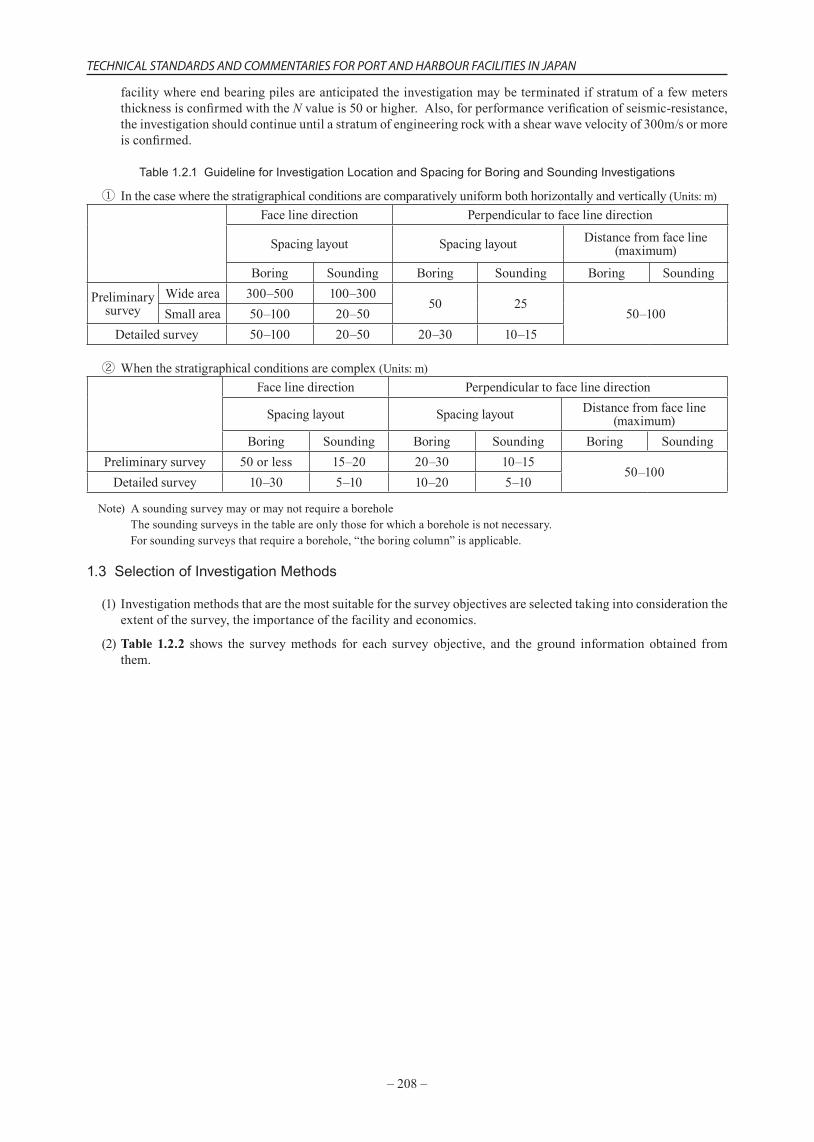
(1)Thelocationofagroundinvestigation,andthespacingandthedepthshouldbedeterminedinaccordancewiththesizeofthefacility,thestressdistributioninthegroundcausedbytheweightofthefacility,andtheuniformityofthestratigraphyoftheground.However,thereisalsotheproblemoftheconstructioncostandimportanceofthefacility,soitisnotpossibletocategoricallyregulatethenumberofsurveypointsandtheirdepth.Indeterminingthe number of survey points the uniformity or non-uniformity of the ground is themost important aspect. Itiseffective tochecktheuniformityornon-uniformityof thegroundfromtheresultsofpast investigations, thetopographyof the land,andgeophysicalexplorationmethodssuchassonicwaveandsurfacewaveexplorationmethods. Automaticallydetermining thespacingofground investigationpoints shouldbeavoidedasmuchaspossible,butforreferenceTable 1.2.1 showsthespacingofgroundinvestigationpointsforboringandsoundingsurveys. Thedepthofthegroundinvestigationshallbesufficienttoconfirmstratawithsufficientbearingcapacity.Whetherastratumhassufficientbearingcapacityornotvariesdependingontheshapeandscaleofthefacility,soitcannotbecategoricallydetermined.However,asaguide,forcomparativelysmallscalefacilitiesorwhenthefoundationsarenotendbearingpiles,theinvestigationmaybeterminatedifstratumofafewmetersthicknessisconfirmedwith theN-valueobtainedfromthestandardpenetration test is30orhigher,or fora largescale
–208–
TECHNICAL STANDARDS AND COMMENTARIES FOR PORT AND HARBOUR FACILITIES IN JAPAN
facilitywhereendbearingpilesareanticipatedtheinvestigationmaybeterminatedifstratumofafewmetersthicknessisconfirmedwiththeNvalueis50orhigher.Also,forperformanceverificationofseismic-resistance,theinvestigationshouldcontinueuntilastratumofengineeringrockwithashearwavevelocityof300m/sormoreisconfirmed.
Table 1.2.1 Guideline for Investigation Location and Spacing for Boring and Sounding Investigations
① Inthecasewherethestratigraphicalconditionsarecomparativelyuniformbothhorizontallyandvertically(Units:m)Facelinedirection Perpendiculartofacelinedirection
Spacinglayout Spacinglayout Distancefromfaceline(maximum)
Boring Sounding Boring Sounding Boring Sounding
Preliminarysurvey
Widearea 300–500 100–30050 25
50–100Smallarea 50–100 20–50Detailedsurvey 50–100 20–50 20–30 10–15
② Whenthestratigraphicalconditionsarecomplex(Units:m)Facelinedirection Perpendiculartofacelinedirection
Spacinglayout Spacinglayout Distancefromfaceline(maximum)
Boring Sounding Boring Sounding Boring SoundingPreliminarysurvey 50orless 15–20 20–30 10–15
50–100Detailedsurvey 10–30 5–10 10–20 5–10
Note)Asoundingsurveymayormaynotrequireaborehole Thesoundingsurveysinthetableareonlythoseforwhichaboreholeisnotnecessary. Forsoundingsurveysthatrequireaborehole,“theboringcolumn”isapplicable.
1.3 Selection of Investigation Methods
(1) Investigationmethodsthatarethemostsuitableforthesurveyobjectivesareselectedtakingintoconsiderationtheextentofthesurvey,theimportanceofthefacilityandeconomics.
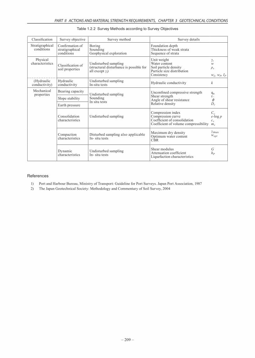
(2)Table 1.2.2 shows the surveymethods for each survey objective, and the ground information obtained fromthem.
PART II ACTIONS AND MATERIAL STRENGTH REQUIREMENTS, CHAPTER 3 GEOTECHNICAL CONDITIONS
–209–
Table 1.2.2Survey Methods according to Survey Objectives
Classification Surveyobjective Surveymethod SurveydetailsStratigraphicalconditions
Confirmationofstratigraphicalconditions
BoringSoundingGeophysicalexploration
FoundationdepthThicknessofweakstrataSequenceofstrata
Physicalcharacteristics Classificationof
soilpropertiesUndisturbedsampling(structuraldisturbanceispossibleforallexceptγt)
UnitweightWatercontentSoilparticledensityParticlesizedistributionConsistency
γtwρs
wL, wP, IP
(Hydraulicconductivity)
Hydraulicconductivity
UndisturbedsamplingIn-situtests Hydraulicconductivity k
Mechanicalproperties
BearingcapacityUndisturbedsamplingSoundingInsitutests
UnconfinedcompressivestrengthShearstrengthAngleofshearresistanceRelativedensity
quτf
Dr
Slopestability
Earthpressure
Consolidationcharacteristics
UndisturbedsamplingCompressionindexCompressioncurveCoefficientofconsolidationCoefficientofvolumecompressibility
Cce-logpcvmv
Compactioncharacteristics
DisturbedsamplingalsoapplicableIn-situtests
MaximumdrydensityOptimumwatercontentCBR
γdmaxwopt
Dynamiccharacteristics
UndisturbedsamplingIn-situtests
ShearmodulusAttenuationcoefficientLiquefactioncharacteristics
GhP
References
1) PortandHarbourBureau,MinistryofTransport:GuidelineforPortSurveys.JapanPortAssociation,19872) TheJapanGeotechnicalSociety:MethodologyandCommentaryofSoilSurvey,2004
–210–
TECHNICAL STANDARDS AND COMMENTARIES FOR PORT AND HARBOUR FACILITIES IN JAPAN
2 Ground Constants2.1 Estimation of Ground Constants 1)
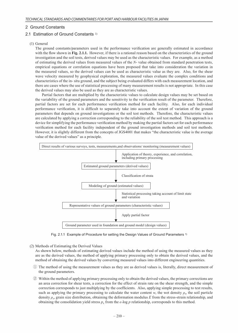
(1)GeneralThe ground constants/parameters used in the performance verification are generally estimated in accordancewiththeflowshowninFig. 2.1.1.However,ifthereisarationalreasonbasedonthecharacteristicsofthegroundinvestigationandthesoiltests,derivedvaluesmaybeusedasthecharacteristicvalues.Forexample,asamethodofestimatingthederivedvaluesfrommeasuredvaluesoftheN-valueobtainedfromstandardpenetrationtests,empirical equations or correlation equations have been proposed that take into consideration the variation inthemeasuredvalues,sothederivedvaluescanbeusedascharacteristicvalueastheyare.Also,fortheshearwavevelocitymeasuredbygeophysicalexploration, themeasuredvaluesevaluate thecomplexconditionsandcharacteristicsofthein-situground,andthesubjectbeingevaluateddifferswitheachmeasurementlocation,andtherearecaseswheretheuseofstatisticalprocessingofmanymeasurementresultsisnotappropriate.Inthiscasethederivedvaluesmayalsobeusedastheyareascharacteristicvalues. Partialfactorsthataremultipliedbythecharacteristicvaluestocalculatedesignvaluesmaybesetbasedonthevariabilityofthegroundparametersandthesensitivitytotheverificationresultoftheparameter.Therefore,partial factors are set for each performance verification method for each facility. Also, for each individualperformance verification, it is difficult to separately take into account the extent of variation of the groundparametersthatdependsongroundinvestigationsorthesoiltestmethods.Therefore,thecharacteristicvaluesarecalculatedbyapplyingacorrectioncorrespondingtothereliabilityofthesoiltestmethod.Thisapproachisadeviceforsimplifyingtheperformanceverificationmethodbymakingthepartialfactorssetforeachperformanceverificationmethod for each facility independent of the ground investigationmethods and soil testmethods.However,itisslightlydifferentfromtheconceptsofJGS4001thatmakes“thecharacteristicvalueistheaveragevalueofthederivedvalues”asaprinciple.
Representative values of ground parameters (characteristic values)
Estimated ground parameters (derived values)
Direct results of various surveys, tests, measurements,and observations/ monitoring (measurement values)
Ground parameter used in foundation and ground model (design values)
Application of theory, experience, and correlation,including primary processing
Statistical processing taking account of limit stateand variation
Apply partial factor
Modeling of ground (estimated values)
Classification of strata
Fig. 2.1.1 Example of Procedure for setting the Design Values of Ground Parameters 1)
(2)MethodsofEstimatingtheDerivedValuesAsshownbelow,methodsofestimatingderivedvaluesincludethemethodofusingthemeasuredvaluesastheyareasthederivedvalues,themethodofapplyingprimaryprocessingonlytoobtainthederivedvalues,andthemethodofobtainingthederivedvaluesbyconvertingmeasuredvaluesintodifferentengineeringquantities.
① Themethodofusingthemeasurementvaluesastheyareasderivedvaluesis,literally,directmeasurementofthegroundparameters.
②Withinthemethodofapplyingprimaryprocessingonlytoobtainthederivedvalues,theprimarycorrectionsareanareacorrectionforsheartests,acorrectionfortheeffectofstrainrateontheshearstrength,andthesimplecorrectioncorrespondstojustmultiplyingbythecoefficients.Also,applyingsimpleprocessingtotestresults,suchasapplyingtheprimaryprocessingtocalculatethewatercontentw,thewetdensityρt,thesoilparticledensityρs,grainsizedistribution,obtainingthedeformationmodulusEfromthestress-strainrelationship,andobtainingtheconsolidationyieldstresspcfromthee-logprelationship,correspondstothismethod.
PART II ACTIONS AND MATERIAL STRENGTH REQUIREMENTS, CHAPTER 3 GEOTECHNICAL CONDITIONS
–211–
③ Themethodofobtainingderivedvaluesbyconvertingthemeasuredvaluesintodifferentengineeringquantitiesisthemethodofconvertingthemeasuredresultsintoengineeringquantitiesbasedontheoreticalorempiricalequations,or,obtainingfittingparametersinaccordancewiththeory.ConvertingN-valuesintotheangleofshearresistance usingempiricalequations,andfittingtheoreticalcurvesofconsolidationtosettlement-timecurvestoobtainthecoefficientofconsolidation cv,correspondtothismethod.
(3)MethodsofsettingtheCharacteristicValues
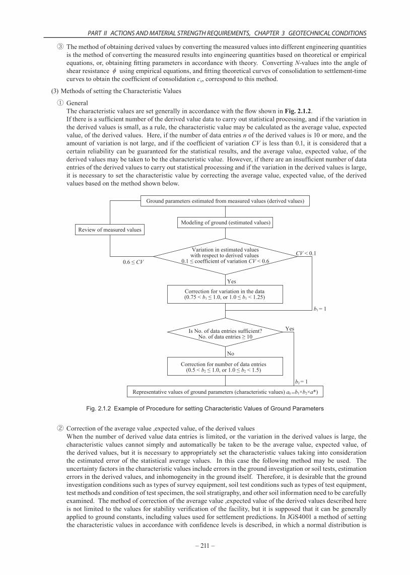
① GeneralThecharacteristicvaluesaresetgenerallyinaccordancewiththeflowshowninFig. 2.1.2.Ifthereisasufficientnumberofthederivedvaluedatatocarryoutstatisticalprocessing,andifthevariationinthederivedvaluesissmall,asarule,thecharacteristicvaluemaybecalculatedastheaveragevalue,expectedvalue,ofthederivedvalues.Here,ifthenumberofdataentriesnofthederivedvaluesis10ormore,andtheamountofvariationisnotlarge,andifthecoefficientofvariationCV islessthan0.1,itisconsideredthatacertain reliabilitycanbeguaranteed for thestatistical results,and theaveragevalue,expectedvalue,of thederivedvaluesmaybetakentobethecharacteristicvalue.However,ifthereareaninsufficientnumberofdataentriesofthederivedvaluestocarryoutstatisticalprocessingandifthevariationinthederivedvaluesislarge,it isnecessarytoset thecharacteristicvaluebycorrectingtheaveragevalue,expectedvalue,of thederivedvaluesbasedonthemethodshownbelow.
Ground parameters estimated from measured values (derived values)
Modeling of ground (estimated values)
Variation in estimated valueswith respect to derived values
0.1 ≤ coefficient of variation CV < 0.6
Review of measured values
Is No. of data entries sufficient?No. of data entries ≥ 10
CV < 0.10.6 ≤ CV
Yes
No
Yes
Representative values of ground parameters (characteristic values) ak =b1×b2×a*)
b1 = 1
b2 = 1
Correction for variation in the data(0.75 < b1 ≤ 1.0, or 1.0 ≤ b1 < 1.25)
Correction for number of data entries(0.5 < b2 ≤ 1.0, or 1.0 ≤ b2 < 1.5)
Fig. 2.1.2Example of Procedure for setting Characteristic Values of Ground Parameters
② Correctionoftheaveragevalue,expectedvalue,ofthederivedvaluesWhenthenumberofderivedvaluedataentriesislimited,orthevariationinthederivedvaluesislarge,thecharacteristic values cannot simply and automatically be taken to be the average value, expected value, ofthederivedvalues,butit isnecessarytoappropriatelysetthecharacteristicvaluestakingintoconsiderationthe estimated error of the statistical average values. In this case the followingmethodmaybe used. Theuncertaintyfactorsinthecharacteristicvaluesincludeerrorsinthegroundinvestigationorsoiltests,estimationerrorsinthederivedvalues,andinhomogeneityinthegrounditself.Therefore,itisdesirablethatthegroundinvestigationconditionssuchastypesofsurveyequipment,soiltestconditionssuchastypesoftestequipment,testmethodsandconditionoftestspecimen,thesoilstratigraphy,andothersoilinformationneedtobecarefullyexamined.Themethodofcorrectionoftheaveragevalue,expectedvalueofthederivedvaluesdescribedhereisnotlimitedtothevaluesforstabilityverificationofthefacility,butit issupposedthatitcanbegenerallyappliedtogroundconstants,includingvaluesusedforsettlementpredictions.InJGS4001amethodofsettingthecharacteristicvaluesinaccordancewithconfidencelevelsisdescribed,inwhichanormaldistributionis
–212–
TECHNICAL STANDARDS AND COMMENTARIES FOR PORT AND HARBOUR FACILITIES IN JAPAN
assumedifthestandarddeviationofthepopulationisknown,andat-distributionisassumedifthestandarddeviationisnotknown.However,whendealingwithgroundparameters,thedistributionandvariationinthederivedvaluesareduetoerrorsinthegroundinvestigationorsoiltests,estimationerrorsinthederivedvalues,andinhomogeneityinthegrounditself,andhence,thisisdifferentfromdealingwithqualityindicesoffactoryproducts,andsimplestatisticalprocessingishardlyapplicable. Toobtainthegroundparameters,whichareobtainedbyadjustingtheaveragevaluesforthestatisticalerrors,andcorrespondtothecharacteristicvalues,forreliability-baseddesign, it isnecessarytoobtainasufficientnumberoftestresultsforstatisticalprocessing.Also,inordertoreflectthesoilinvestigationandsoiltestresultsintheperformanceverification,itisnecessarytomodelthedistributioninthedepthdirectionoftheestimatedvaluesa*ofthegroundparameteraasconstantwithdepth(a*=c1),linearlyincreasingwithdepth(a*=c1z+c2),orashavingaquadraticdistributionwithdepth(a*=c1z2+c2z+c3).Here,c1,c2,andc3areconstants.Ifacertainrangeofdepthistobemodeled,asufficientnumberoftestsare10ormoredataentriesinordertocarryoutstatisticalprocessingonthegroundmodel.Thereliabilityofgroundparametersobtainedfromdifferentsoiltestmethodssuchastheundrainedshearstrengthofcohesivesoilsobtainedfromtriaxialtestsandunconfinedcompressiontestsdiffers,sodifferentpartialfactorsshouldbesetaccordingly,butitisnotknowntowhatextentthefactorsshoulddiffer.However,itiswellknownthatthecoefficientsofvariationofthetwotestresultsaresignificantlydifferent.Basedonthisthecharacteristicvaluesarecalculatednotsimplyasthearithmeticmean,butbymultiplicationbyacorrectioncoefficientthattakesintoaccountthevariationofthederivedvaluestotheestimatedvalues.However,thisisbasedontheassumptionthatthereisasufficientnumberofdataentriestocarryoutstatisticalprocessing,soifthenumberofdataentriesisinsufficient,itisnecessarytofurthersetthecharacteristicvaluesonthesafetyside,bymultiplyingbyacorrectioncoefficientforthenumberofdatapoints.Inotherwords,thecharacteristicvaluesarecalculatedfromthefollowingequation (2.1.1)orequation (2.1.2).Here,ifitisreasonabletoconsiderthevariationonlogarithmicaxes,equation (2.1.2)isused.
(2.1.1)
(2.1.2)
where ak :representativevalueofgroundparameter(characteristicvalue) b1 :correctioncoefficientforvariationinthederivedvalues b2 :correctioncoefficientfornumberofdatapointsofderivedvalues a* :modelvalueofthegroundparameter(estimatedvalue)
Aspecificmethodofsettingthecorrectioncoefficient isdescribedbelow.However,whendealingwiththeunitweightofthein-situgroundinstabilityanalysis,fordeterminingthevaluesatwhichtheactionsideandtheresistancesidearesubstantiallyinbalance,thecorrectioncoefficientsmaybetakentobeb1=1,b2=1.
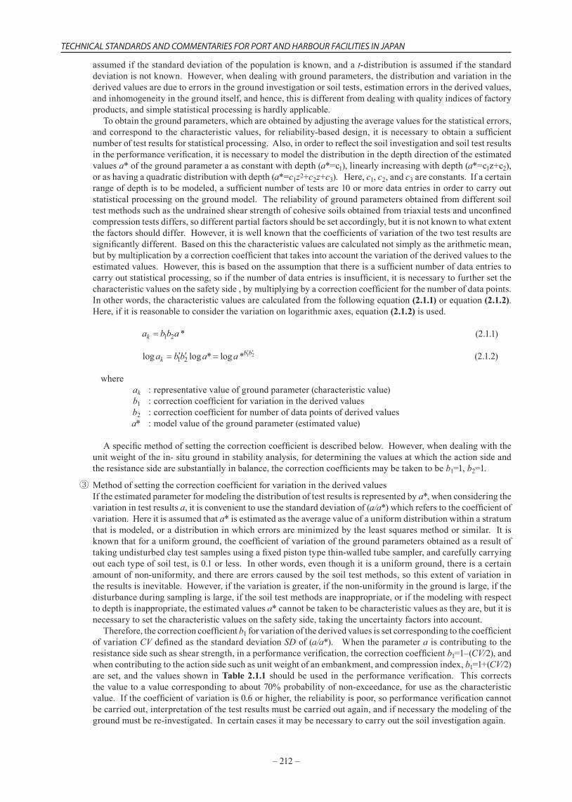
③MethodofsettingthecorrectioncoefficientforvariationinthederivedvaluesIftheestimatedparameterformodelingthedistributionoftestresultsisrepresentedbya*,whenconsideringthevariationintestresultsa,itisconvenienttousethestandarddeviationof(a/a*)whichreferstothecoefficientofvariation.Hereitisassumedthata*isestimatedastheaveragevalueofauniformdistributionwithinastratumthatismodeled,oradistributioninwhicherrorsareminimizedbytheleastsquaresmethodorsimilar.Itisknownthatforauniformground,thecoefficientofvariationofthegroundparametersobtainedasaresultoftakingundisturbedclaytestsamplesusingafixedpistontypethin-walledtubesampler,andcarefullycarryingouteachtypeofsoiltest,is0.1orless.Inotherwords,eventhoughitisauniformground,thereisacertainamountofnon-uniformity,andthereareerrorscausedbythesoiltestmethods,sothisextentofvariationintheresultsisinevitable.However,ifthevariationisgreater,ifthenon-uniformityinthegroundislarge,ifthedisturbanceduringsamplingislarge,ifthesoiltestmethodsareinappropriate,orifthemodelingwithrespecttodepthisinappropriate,theestimatedvaluesa*cannotbetakentobecharacteristicvaluesastheyare,butitisnecessarytosetthecharacteristicvaluesonthesafetyside,takingtheuncertaintyfactorsintoaccount. Therefore,thecorrectioncoefficientb1forvariationofthederivedvaluesissetcorrespondingtothecoefficientofvariationCVdefinedasthestandarddeviationSDof(a/a*).Whentheparameteraiscontributingtotheresistancesidesuchasshearstrength,inaperformanceverification,thecorrectioncoefficientb1=1–(CV/2),andwhencontributingtotheactionsidesuchasunitweightofanembankment,andcompressionindex,b1=1+(CV/2)are set, and thevalues shown inTable 2.1.1 shouldbeused in theperformanceverification. Thiscorrectsthevaluetoavaluecorrespondingtoabout70%probabilityofnon-exceedance,foruseasthecharacteristicvalue.Ifthecoefficientofvariationis0.6orhigher,thereliabilityispoor,soperformanceverificationcannotbecarriedout,interpretationofthetestresultsmustbecarriedoutagain,andifnecessarythemodelingofthegroundmustbere-investigated.Incertaincasesitmaybenecessarytocarryoutthesoilinvestigationagain.
PART II ACTIONS AND MATERIAL STRENGTH REQUIREMENTS, CHAPTER 3 GEOTECHNICAL CONDITIONS
–213–
Table 2.1.1 Values of Correction Coefficients
CoefficientofvariationCV
Correctioncoefficientb1Whenitisnecessarytocorrectthe
characteristicvaluetoavaluesmallerthanthederivedvalues
Whenitisnecessarytocorrectthecharacteristicvaluetoavaluelargerthan
thederivedvalues≥0,<0.1 1.0 1.0≥0.1,<0.15 0.95 1.05≥0.15,<0.25 0.9 1.1≥0.25,<0.4 0.85 1.15≥0.4,<0.6 0.75 1.25≥0.6 Re-investigatetheinterpretationoftheresultsorthemodeling,orre-dothesurvey
Thegroundparametersincludeparameterswhoseresultsareevaluatedaslogarithmicdistributions,suchastheconsolidationyieldstresspc,thecoefficientofconsolidationcv,andthecoefficientofvolumecompressibilitymv. Inorder toobtain thecharacteristicvaluesof theseparameters,several testsarecarriedout,and if thegroundistobetreatedasuniform,theseparametersaredistributedaslog-normal,soitisreasonabletoconsiderthevariationonthelogarithmicaxis.Inotherwords,fortheparametera,ifthestandarddeviationof(loga)/(loga*)isSD,andthisbecomesthecoefficientofvariationCV,thevaluesinTable 2.1.1canbeusedastheyareasthecorrectioncoefficientb1onthelogarithmicaxis.Ontheotherhand,fortheangleofshearresistance ,thevariationof itselfisnotconsidered,butthevariationoftan isconsidered.Inthecaseoftheangleofshearresistanceofamoundmaterial,ifthevalueusedintheperformanceverificationisspecifiedbasedonexperience,thespecifiedvaluealreadyhastheeffectofvariationtakenintoconsideration,soitisnotnecessarytoconsideracorrectioncoefficient.Thecorrectioncoefficientsshownhereareusedaftercarryingoutstatisticalprocessinginordertoobtainthecharacteristicvaluesfromthereportedsoiltestresults.Therefore,itisnecessarytobeawarethatthecoefficientsofvariationinTable 2.1.1donotindicatethelevelofvariationobtainedfromsoilinvestigationsorsoiltestresults.
④MethodofsettingthecorrectioncoefficientforthenumberofdataentriesofthederivedvaluesForthe Method of setting the correction coefficient for variation in the derived valuesin ③above,itwasassumedthatthenumberofdatapointsissufficienttocarryoutstatisticalprocessing.However,inthecasewherethenumberofdatapointsisinsufficientforcarryingoutstatisticalprocessing,thecorrectioncoefficientb2forthenumberofdataentriesofderivedvaluesissetasfollows.Inotherwords,ifthenumberofdataentriesnis10ormore,therewillbeacertainreliabilityinthestatisticalresults,butifthenumberisinsufficientthecorrectioncoefficientshouldbesettob2={1±(0.5/n)}.Herethenegativesignisusedwhenitisnecessarytocorrectthecharacteristicvalueofagroundparameterusedinperformanceverificationtowardsmallervaluesthanthederivedvalues,andthepositivesignisusedwhenitisnecessarytocorrectthevaluetowardlargervaluesthanthederivedvalues.Fortheperformanceverificationtheremustbeatleasttwoormoredataentries.However,eveninthecasewherethereisonlyonedataentries,ifotherparametersforexampleN-valueorgrainsizedistributionhavebeenobtained,andifthedistributioninthedepthdirectionismodeledfromacorrelationwiththeseprovidedonlycommonlyknowncorrelationsareused,thenthatonedataentrymaybeusedintheperformanceverification.Inthiscase,b1=1,andb2=1±0.5areassumed.
⑤MethodofsettingthecharacteristicvaluestakingthemodeoftheperformanceverificationintoaccountThegroundconstantsforconsolidationandthegroundconstantsforsheararenotmutuallyindependent.Intheperformanceverification,iftheseconstantsareconsideredtobeindependent,thecharacteristicvaluescanbeobtainedtakingintoconsiderationthereliabilityoftherespectiveparameters.However,ifastrengthincreasedue to consolidation is expected for stability evaluation, theparameters in respect of consolidation and theparametersinrespectofshearingmustbecloselylinked.Inthesecircumstances,intheprocessofobtainingcharacteristicvaluesfromderivedvalues,theparametersaremodeledasmutuallylinkedwhenmodelingthedistributionofsoiltestresultstoderiveestimatedvalues.Forexample,thecharacteristicvaluesmustbesetbystatisticalprocessingforthevariation,toestimatecompatiblegroundparameters,takingintoconsiderationtherelationshipcu=m×OCR×σ'v0betweentheeffectivesoiloverburdenpressureσ'v0,theconsolidationyieldstresspc,andtheundrainedshearstrengthcu,usingthestrengthincreaseratiom=cu/pc,andtheoverconsolidationratioOCR=pc/σ'v0.
(4)MethodofCalculatingDesignValuesInthevariouscalculationswhenthegroundparametersareusedinperformanceverification,designvaluesareobtainedbymultiplyingthecharacteristicvaluesbyapartialfactorγ.Avalueofthepartialfactorγmaybesetforeachperformanceverificationmethodforeachfacility,butifnotspecifiedotherwise,γmaybetakentobe1.0.
–214–
TECHNICAL STANDARDS AND COMMENTARIES FOR PORT AND HARBOUR FACILITIES IN JAPAN
2.2 Physical Properties of Soils2.2.1 Unit Weight of Soil
(1)Theunitweightmustbeobtainedbycollectingundisturbedsamplesonsite,ordirectlyobtainingitonsite.
(2)Theunitweightisnormallytheweightperunitvolumeinair,andincludesthewetunitweightanddryunitweight.Also,theunitweightinwater(weightperunitvolumefromwhichbuoyancyisdeducted)isreferredtoastheimmersedunitweight.Forthemeasurementoftheunitweight,methodsofcollectingundisturbedsamplesofclaysoilshavebeenestablished,anditispossibletoobtaintestsamplesthatarerepresentativeofthesoilin-situ.Thereforetheunitweightofclaysoilscanbeobtainedfromlaboratorytests.However,theunitweightofsandysoilsorsandmustbeobtaineddirectlyin-situ. Thewetunitweight isoneof the indices indicating the fundamentalpropertiesof a soil, and isused forrecognizingthesoilstiffness,anddegreeoflooseness,andforcalculating,theweightofasoilmassandthevoidratio.
①WetunitweightThewetunitweightisgenerallyexpressedasshowninequation (2.2.1),bycombiningboththeweightofsoilparticlesperunitvolumeandtheweightofwaterwithinthevoid.
(2.2.1)
where γt :wetunitweight(kN/m3) ρt :bulkdensity(t/m3) ρs :soilparticledensity(t/m3) e :voidratio Sr :degreeofsaturation(%) w :watercontent(%) ρw :densityofseawater(t/m3) g :gravitationalacceleration(m/s2)
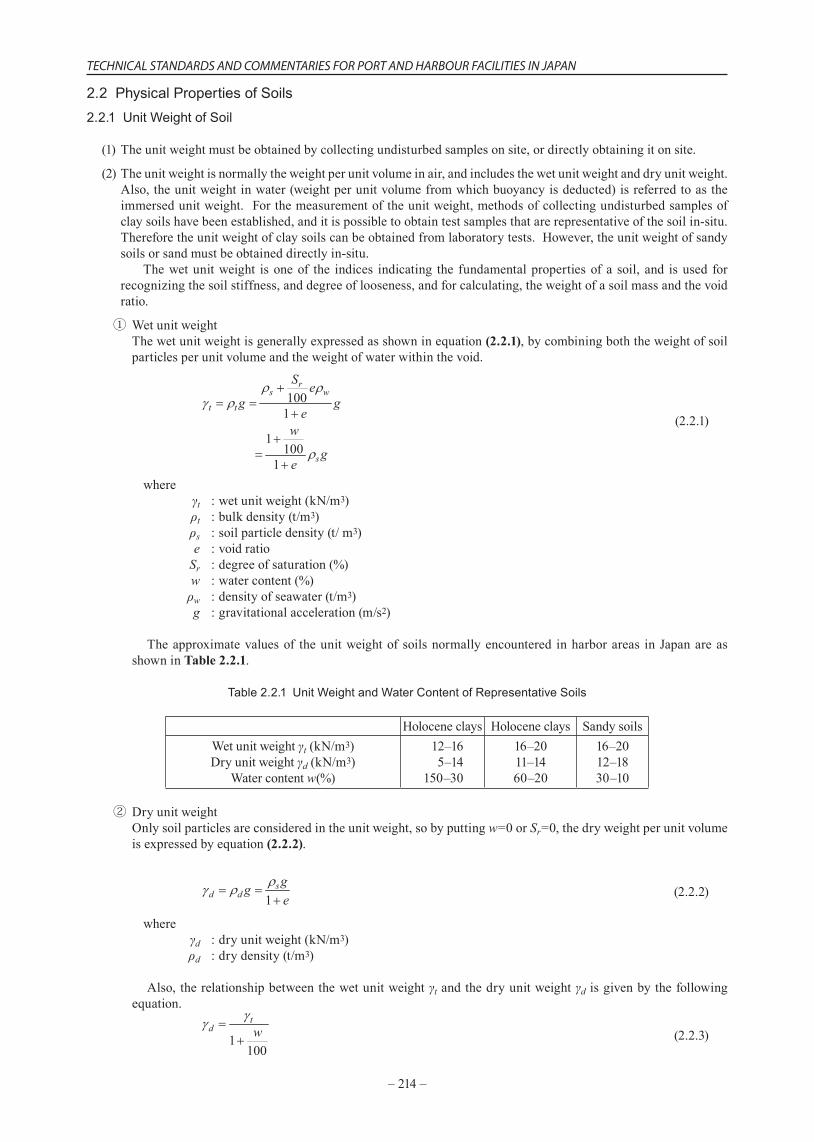
Theapproximatevaluesof theunitweightof soilsnormallyencountered inharborareas inJapanareasshowninTable 2.2.1.
Table 2.2.1Unit Weight and Water Content of Representative Soils
Holoceneclays Holoceneclays SandysoilsWetunitweightγt(kN/m3)Dryunitweightγd(kN/m3)
Watercontentw(%)
12–165–14
150–30
16–2011–1460–20
16–2012–1830–10
② DryunitweightOnlysoilparticlesareconsideredintheunitweight,sobyputtingw=0orSr=0,thedryweightperunitvolumeisexpressedbyequation (2.2.2).
(2.2.2)
where γd :dryunitweight(kN/m3) ρd :drydensity(t/m3)
Also, therelationshipbetweenthewetunitweightγtandthedryunitweightγd isgivenbythefollowingequation.
(2.2.3)
PART II ACTIONS AND MATERIAL STRENGTH REQUIREMENTS, CHAPTER 3 GEOTECHNICAL CONDITIONS
–215–
③ ImmersedunitweightIfthevoidiscompletelysaturatedwithwater,theimmersedunitweightisexpressedbyequation (2.2.4)takingbuoyancyintoaccount.
(2.2.4)
whereγ' :immersedunitweight(kN/m3)γsat :saturatedunitweight(kN/m3)
Although the unitweight ofwater γw is somewhat dependent on salt concentration and temperature, itscorrectvalueisknown.Therefore,whenobtainingthecharacteristicvaluesofasaturatedfoundationtakingthevariationinunitweightintoaccount,thevariationinγ'shouldbeconsidered,notγsat.Inotherwords,whenmultiplyingthecharacteristicvaluesbyapartialfactortoobtainthedesignvalues,thereisnonecessitytoapplyapartialfactortotheunitweightofwaterγw,sotheimmersedunitweightγ'ismultipliedbythepartialfactor,notthesaturatedunitweightγsat.
(3)MeasurementofUnitWeightIn-situMethodsfordirectlyobtainingtheunitweightin-situincludemethodsinwhichmeasurementisonlypossiblenearthegroundsurface,andmethodsofmeasurementinfirmground.Theformerincludesforexampletheso-calledsandreplacementmethod,asimpleandeasymethodasprescribedbyJISA1214Method of Soil Density TestbySand Replacement Method.Also,thelatterincludesexamplemethodsofmeasurementusingradioisotopes(RI).
①MethodsusingthesandreplacementmethodThesandreplacementmethodismainlyappliedtomeasurementonlandnearthegroundsurfaceforcontrolofearthworks,butitcanbeuseddowntoacertaindepthwherepitscanbeexcavated.ThismeasurementmethodisdescribedinJISA1214.
② Radioisotopes(RI)InrecentyearstheuseofRIhasbecomecomparativelyeasy,andalthoughtherearestrictlawsandregulationssuchasthe Law to Prevent Radiological Hazards Caused by Radioactive Isotopes.(LawNo.167,1957)anditsassociatedregulations,therehavebeenmanycasesofmeasurementusingaγ-raydensitometerasanin-situtestwhereitisdifficulttoobtainundisturbedsamplesofsandandsandysoil.Incidentally,theselegalrestrictionsdonotapplyinthecaseofsealedradioactivesourceswhoseradiationsourcestrengthis3.7MBq(megabequerel)orless. Therearetwotypesofγ-raydensitometerthatuseRI:asurfacetypeandaninsertedtype,andthesearedescribedinSoil Density TestMethods using RI Equipment,JGS1614,theStandardofGeotechnicalSocietyofJapan.Thesurfacetypeisappliedtomeasurementnearthegroundsurface,asimpliedbyitsname,andisusedforcontrolofearthworkssameasthesandreplacementmethod. Thesurfacetypeisfurtherclassifiedintobackscattering typesandtransmissiontypes. Measuringequipmentusingthe initiallydevelopedbackscatteringmethodisfrequentlyused,butinrecentyearsequipmentusingthetransmissionmethodhasbecomepopularbecauseof its accuracy. On theotherhand, the insertion type is applied tomeasuring thedensitydistributionintheverticaldirection,inotherwordsforsurveysinthedepthdirection.Forexample,itisusedfor investigating thedensitydistribution in thedepthdirection forgroundsurveys, fordetermining thesoilimprovementeffectbydensitymeasurementofreplacedsand,andmeasurementofthedensityoffilledsandincaissons. TheRImethodhas theadvantage that it isanon-destructive test fromwhich the in- situdensitycanbedirectlymeasured.Also,althoughthemeasurementoperationitselfissimplesoithasahighusabilityvalue,ontheotherhandbecausethereisdangerassociatedwiththeradioactivematerialtherearemanyregulationsregardingitshandling,soitcannotbesimplybroughtoutandusedin-situ.Inaddition,insurveysassociatedwithportconstruction,theinsertedtypeismainlyused,sothereisanoperationofinsertingtheequipmentintotheaccesspipe.Themeasurementaccuracyisgovernedbythematerialandqualityofthepipe,ortheinsertionaccuracy,inotherwords,themeasurementaccuracyisgovernedbythedisturbanceofthesurroundingswhenthepipeisinserted,andhowgoodthecontactbetweenthepipeandthesoilis,socautionisnecessary.RecentlytheRIconepenetrometer,whichincorporatesRIinaconeprobe,isbeingdevelopedasadevicecapableofdirectlypenetratingintothegroundforsurveys.
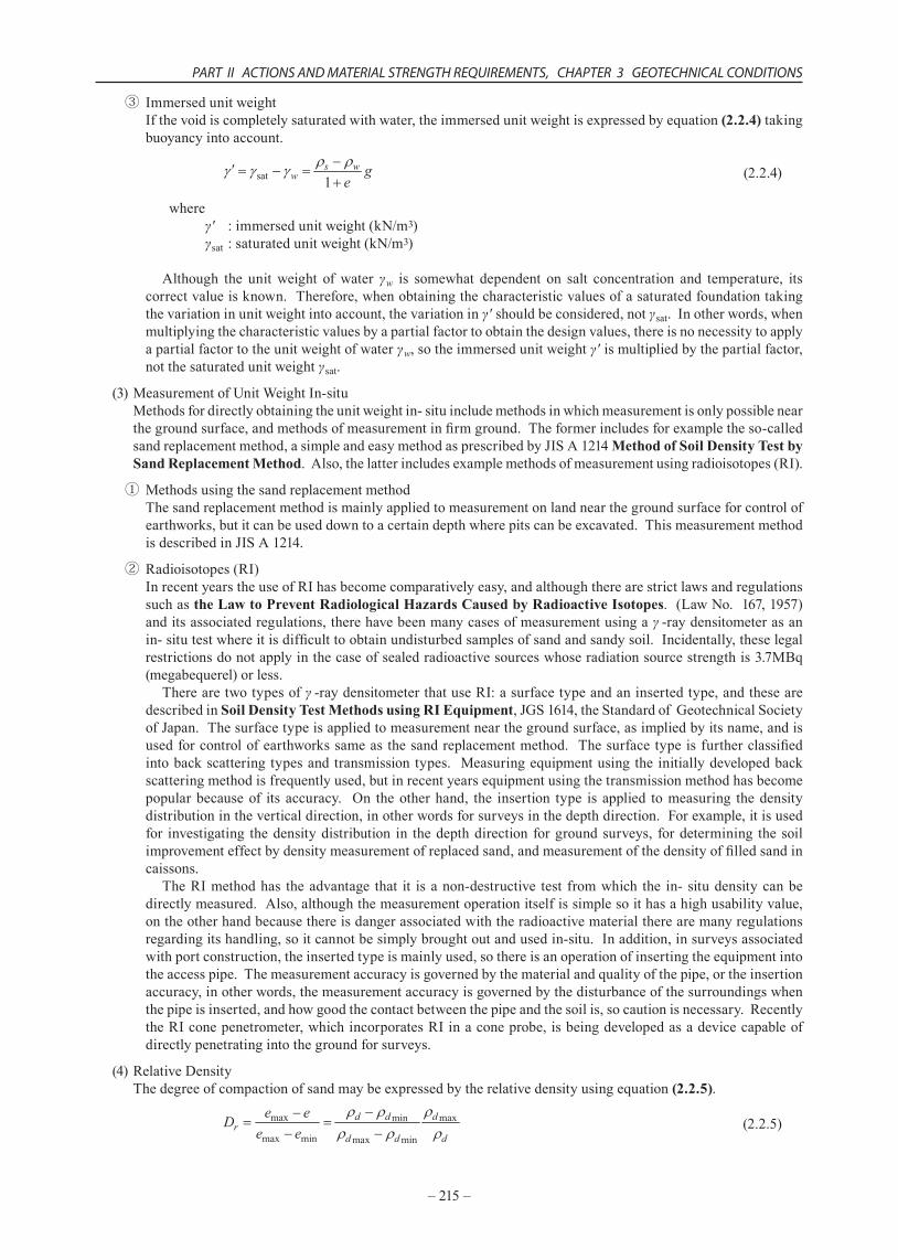
(4)RelativeDensityThedegreeofcompactionofsandmaybeexpressedbytherelativedensityusingequation(2.2.5).
(2.2.5)
–216–
TECHNICAL STANDARDS AND COMMENTARIES FOR PORT AND HARBOUR FACILITIES IN JAPAN
where,Dr :relativedensity
emax :voidratiointhelooseststateemin :voidratiointhedenseststatee :voidratiointhepresentstateofthetestsample
ρdmin :drydensityinthelooseststate(g/cm3)ρdmax :drydensityinthedenseststate(g/cm3)
ρd :drydensityinthepresentstateofthetestsample(g/cm3)
Thedensityofsandisgreatlyaffectedbytheshapeoftheparticlesandbythegrainsizecomposition.Sofromtheunitweightsandthevoidratioscalculatedfromit,thedensityofsandcannotbecorrectlyevaluated.Therefore,therelativedensityisusedtoindicatetherelativevaluewithintherangeofvoidratiosthatcanbetakenwiththissoil.Measurementofemax,emin,(ρdmin,ρdmax)forobtainingDrcanbecarriedoutinaccordancewithJapaneseIndustrialStandardJISA1224Method of Measurement of the Minimum and Maximum Density of Sand. Itisdifficulttotakeundisturbedsamplesofsand,sotherelativedensityisfrequentlymeasuredindirectlybysounding.(see2.3.4(4) Angle of shear resistance of sandy ground).
2.2.2 Classification of Soils
(1)Soilclassificationisperformedbythegradingforcoarsesoilsandbytheconsistencyforfinesoils.
(2)Mechanicalpropertiesofsoilsuchasstrengthordeformationhaveacloserelationshipwiththegradingforcoarsesoils,andwiththeconsistencyforfinesoils.
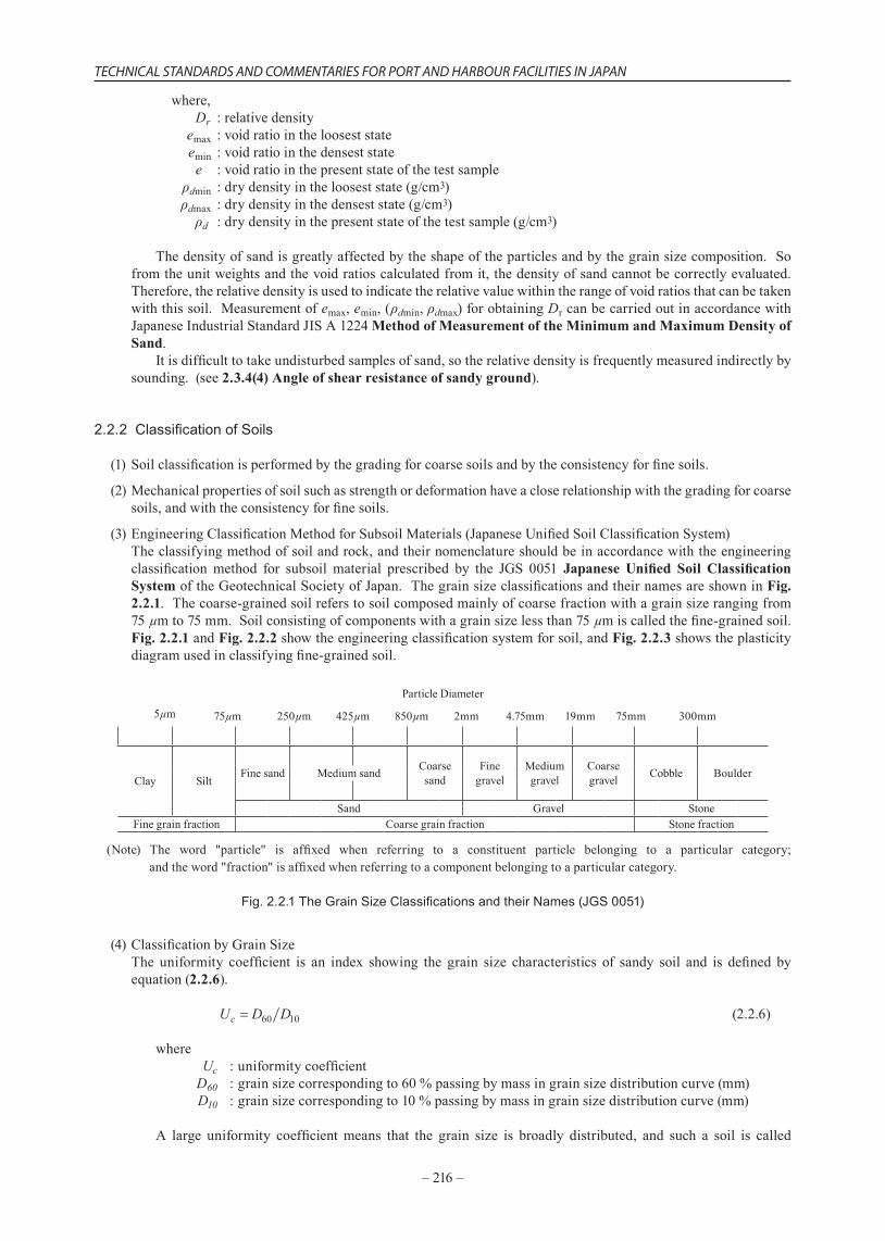
(3)EngineeringClassificationMethodforSubsoilMaterials(JapaneseUnifiedSoilClassificationSystem)Theclassifyingmethodofsoilandrock,andtheirnomenclatureshouldbeinaccordancewiththeengineeringclassificationmethod for subsoil material prescribed by the JGS 0051 Japanese Unified Soil Classification SystemoftheGeotechnicalSocietyofJapan.ThegrainsizeclassificationsandtheirnamesareshowninFig. 2.2.1.Thecoarse-grainedsoilreferstosoilcomposedmainlyofcoarsefractionwithagrainsizerangingfrom75µmto75mm.Soilconsistingofcomponentswithagrainsizelessthan75µmiscalledthefine-grainedsoil.Fig. 2.2.1 and Fig. 2.2.2 showtheengineeringclassificationsystemforsoil,andFig. 2.2.3 showstheplasticitydiagramusedinclassifyingfine-grainedsoil.
ParticleDiameter
5µm 75µm 250µm 425µm 850µm 2mm 4.75mm 19mm 75mm 300mm
Clay SiltFinesand Coarse
sandFinegravel
Mediumgravel
Coarsegravel Cobble BoulderMediumsand
Sand Gravel StoneFinegrainfraction Coarsegrainfraction Stonefraction
(Note) The word "particle" is affixed when referring to a constituent particle belonging to a particular category; andtheword"fraction"isaffixedwhenreferringtoacomponentbelongingtoaparticularcategory.
Fig. 2.2.1 The Grain Size Classifications and their Names (JGS 0051)
(4)ClassificationbyGrainSizeThe uniformity coefficient is an index showing the grain size characteristics of sandy soil and is defined byequation(2.2.6).
(2.2.6)
where Uc :uniformitycoefficientD60 :grainsizecorrespondingto60%passingbymassingrainsizedistributioncurve(mm)D10 :grainsizecorrespondingto10%passingbymassingrainsizedistributioncurve(mm)
A large uniformity coefficientmeans that the grain size is broadly distributed, and such a soil is called
PART II ACTIONS AND MATERIAL STRENGTH REQUIREMENTS, CHAPTER 3 GEOTECHNICAL CONDITIONS
–217–
“wellgraded”.Incontrast,asmallvalueofUcmeansthatthegrainsizedistributionisnarroworthegrainsizeisuniform.Suchasoiliscalled“poorlygraded”. IntheJapaneseUnifiedSoilClassificationSystem,coarsesoilwherefinecontentsarelessthan5%ofthetotalmassisfurtherdividedinto“broadly-distributedsoil”and“uniformedsoil”.
Broadly-distributedsoil :10 ≤ UcUniformedsoil :Uc<10
2.2.3 Hydraulic Conductivity of Soil
(1)Whentheseepageflowinacompletelysaturatedgroundisasteadylaminarflow,thehydraulicconductivityshallbeestimatedbyusingDarcy’slaw.
(2)Thehydraulicconductivitykiscalculatedbyequation(2.2.7),takingintoaccountofthemeasurementofcross-sectionalareaofsoilA,hydraulicgradientiandvolumeofseepageflowinunittime.
(2.2.7)where
k :coefficientofpermeability(cm/s) q :volumeofwaterflowinsoilinunittime(cm3/s)
i :hydraulicgradient,
h :headloss(cm) L :lengthoftheseepagepath(cm) A :cross-sectionalarea(cm2)
Themeasurement fordeterminingcoefficientofpermeabilityk includes a laboratorypermeability testofundisturbedsoilsamplestakenin-situ,orain-situpermeabilitytest.
(3)ApproximatevaluesofthecoefficientofpermeabilityHazenshowedthattheeffectivegrainsizeD10andthepermeabilityofsandkarerelated,andgaveequation(2.2.8)tocalculatekofrelativelyuniformsandwiththeuniformitycoefficientofUclessthan5,andtheeffectivegrainsizeD10from0.1mmto0.3mm.5)
(2.2.8)where
k :coefficientofpermeability(cm/s) C :constant(C=100(1/cm·s)) D10 :grainsizecalledastheeffectivegrainsizecorrespondingto10percentagepassingofmass
ingrainsizedistributioncurve(cm)
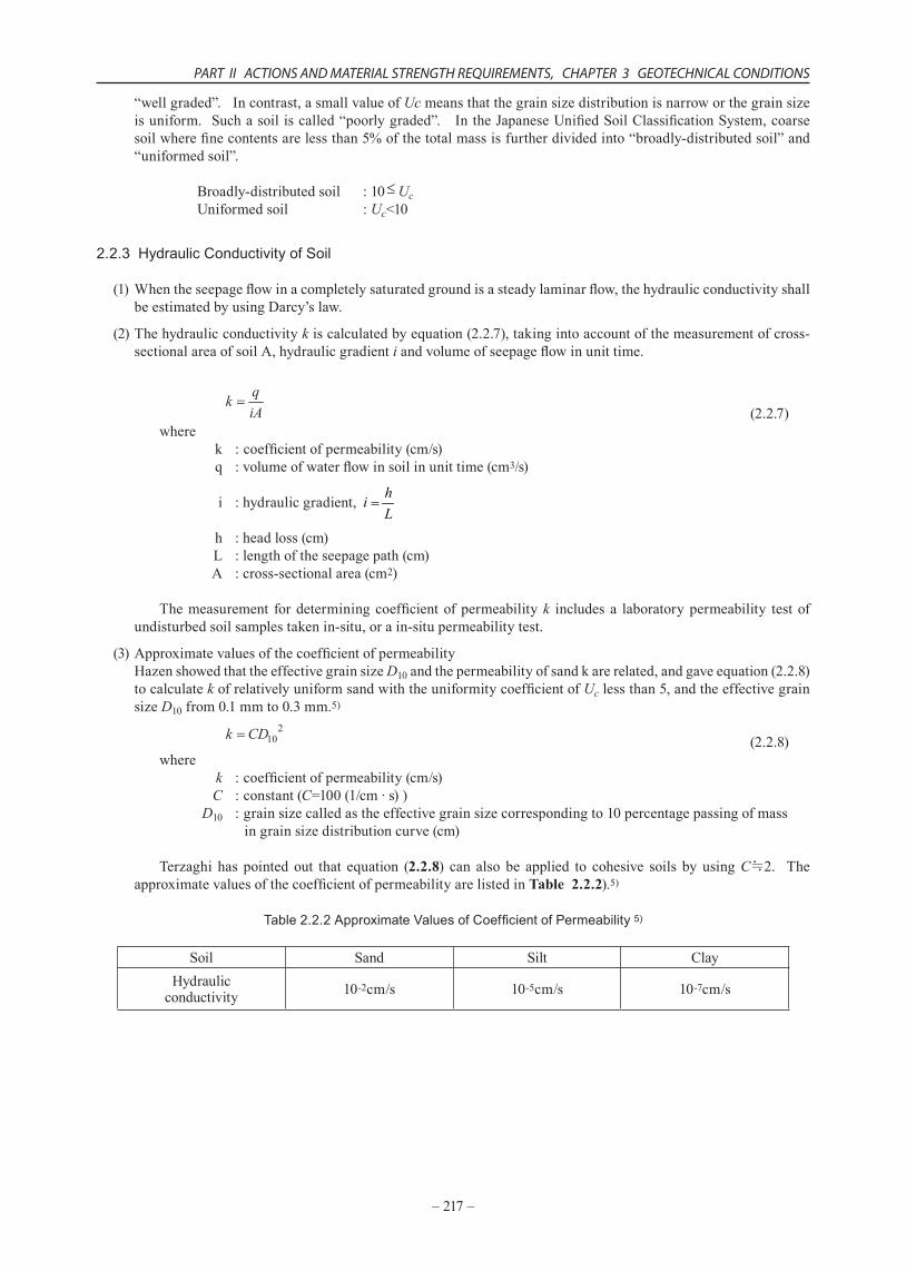
Terzaghi has pointed out that equation (2.2.8) can also be applied to cohesive soils by usingC≒2. TheapproximatevaluesofthecoefficientofpermeabilityarelistedinTable 2.2.2).5)
Table 2.2.2 Approximate Values of Coefficient of Permeability 5)
Soil Sand Silt ClayHydraulicconductivity 10-2cm/s 10-5cm/s 10-7cm/s
–218–
TECHNICAL STANDARDS AND COMMENTARIES FOR PORT AND HARBOUR FACILITIES IN JAPAN
2.3 Mechanical Properties of Soil2.3.1 Elastic Constants
(1)Whenanalyzingsoilbehaviorasanelasticbody,theelasticconstantsaredeterminedwithdueconsiderationforthenonlinearityofstress-strainrelationofsoils.
(2)Whenanalyzingsoilbehaviorasanelasticbody,thedeformationmodulusandPoisson’sratioarenormallyusedastheelasticconstants.Becauseofthestrongnonlinearityofstress-strainrelationshipofsoil,theelasticconstantsinanalysismustbedeterminedbyconsideringthestrainlevelofthegroundtobeanalyzed.
(3)StrainDependencyofDeformationModulusThestress-strainrelationofsoilusuallyshowsastrongnonlinearity.Whenthestrainleveliswithinarangeof10-5orlessnamely0.001%orless,thedeformationmodulusislargestandnearlyconstant.ThismaximumvalueEmaxiscorrespondingtothemeasuredvalueinthedynamictestingmethodssuchastheelasticwaveexploration,andiscalledthedynamicelasticitymodulus.Asthestrainlevelincreases,theelasticitymodulusdecreases.ThesecantmodulusE50,determinedfromaconventionalunconfinedcompressiontestoratriaxialcompressiontest,isconsideredasthedeformationmoduluswhenthestrainisoftheorderof10-3(0.1%).Whenconductinganelasticanalysisofsoil,itisnecessarytodeterminetheelasticconstantbyconsideringthestrainlevelofthesoil.
(4)RelationshipbetweenUndrainedShearStrengthandDeformationModulusForcohesivesoils,theapproximatevaluesfortheinitialtangentelasticmodulusEi,andthesecantelasticmodulusE50canbedeterminedbyusingequation(2.3.1)andequation(2.3.2).7)
(2.3.1)
(2.3.2)
where Ei :initialtangentelasticmodulus(kN/m2) E50 :secantelasticmodulus(kN/m2) cu :undrainedshearstrength(kN/m2)
Theequation(2.3.1)isapplicableonlyforhighlystructuredmarinecohesivesoilwithhighplasticity.
(5)Poisson’sRatioFordeterminingPoisson’sratioofsoil,thereisnoestablishedmethodcurrently,althoughanumberofmethodshavebeenproposed.Practically,v =1/2isusedforundrainedconditionsofsaturatedsoil,andv =1/3–1/2isusedformanyothersituations.
2.3.2 Compression and Consolidation Characteristics
(1)CompressioncharacteristicsofsoilandthecoefficientsforestimatingsettlementoffoundationsduetoconsolidationcanbecalculatedfromthevaluesobtainedbasedonJISA1217Test Method forConsolidation Testof Soils Using Incremental Loading.
(2)When soil is loaded one-dimensionally, compression of the structure with the soil particles which causessettlementisreferredtoascompression.Ifthevoidsofthesoilaresaturatedwithwater,itisnecessaryfortheporewatertobedrainedinordertocontactthestructurewiththesoilparticles.Forsandysoilswithhighhydraulicconductivity,drainageisfast,socontractionoccursimmediatelyafterloadingandissooncompleted.However,forcohesivesoilgroundthehydraulicconductivityisverylow,soalongperiodoftimeisneededfordrainage,andcompressionsettlementoccursslowly.Thisphenomenoninwhichcompressionsettlementincohesivesoilgroundoccursoveralongperiodoftimeisreferredtoasconsolidation. Theconsolidationcharacteristicsofsoilsareusednotonlyforcalculatingthesettlementduetoloading,butalsoforestimatingtheincreaseinshearstrengthofsoilsinsoilimprovementwork.
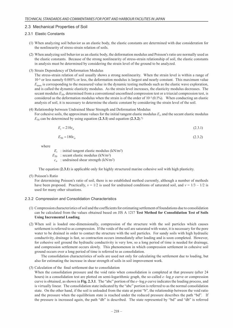
(3)CalculationofthefinalsettlementduetoconsolidationWhentheconsolidationpressureand thevoidratiowhenconsolidation iscompletedat thatpressure(after24hours)inaconsolidationtestareplottedonsemi-logarithmicgraph,theso-callede–logpcurveorcompressioncurveisobtained,asshownin Fig. 2.3.1.The“abc”portionofthee–logpcurveindicatestheloadingprocess,andisvirtuallylinear.Theconsolidationstateindicatedbythe“abc”portionisreferredtoasthenormalconsolidationstate.Ontheotherhand,ifthesoilisunloadedfromthestateatpoint“b”,therelationshipbetweenthevoidratioandthepressurewhentheequilibriumstateisreachedunderthereducedpressuredescribesthepath“bd”.Ifthepressureisincreasedagain,thepath“db”isdescribed.Thestaterepresentedby“bd”and“db”isreferred
PART II ACTIONS AND MATERIAL STRENGTH REQUIREMENTS, CHAPTER 3 GEOTECHNICAL CONDITIONS
–219–
toastheoverconsolidation.Whenaconsolidationtestiscarriedout,thepath“d→b→c”isdescribed,thepoint“b” isobtainedat theboundaryof“d→b”indicating theelasticdeformationand“b→c”indicating theplasticdeformation,andthepressurecorrespondingtothisboundaryisreferredtoastheconsolidationyieldstress.
a
b
c
d
log p
1
2
1 2
e
e
e
p p
Fig. 2.3.1 e–log p Relationship during Consolidation
The relationshipbetween thevoid ratioe and thepressurep for the segment“abc”,normalconsolidationdomaininFig. 2.3.1 isexpressedbyequation(2.3.3).
(2.3.3)
whereCc isanon-dimensionalnumbershowingthedegreeofinclinationofsegment“abc”andiscalledthecompressionindex.
Thefinalsettlementresultingfromtheconsolidationloadcanbecalculatedusingthreemethods:thee-logp curvemethod,theCc method,andthecoefficientofvolumecompressibilitymvmethod.Thedecreaseinvoidratio ewhenthepressureincreasesfromtheoverburdenpressurein-situp0to(p0+ p)canbedeterminedbydirectlyreadingthee–logprelationshipcurveobtainedfromconsolidationtests.Otherwise,ifthesettlementisexpectedtobeoverestimatedtothesafeside,itcanalsobeevaluatedbyequation (2.3.4)usingequation (2.3.3).
(2.3.4)
In thee-logpcurvemethod, thesettlementS iscalculatedbythefollowingequationusing eeitherreaddirectlyordeterminedfromequation (2.3.4):
(2.3.5)
where h :thicknessoflayer
IntheCc method,thesettlementS iscalculatedbythefollowingequation(2.3.6):
(2.3.6)
Thisequationcorrespondstothatwherebyequation (2.3.4)issubstitutedinequation (2.3.5).Thecoefficientofvolumecompressibilitymv isusedforestimatingsettlementandtheamountofcompressionbyaloadisproportionaltomv.However,thisiseffectiveonlywithsmallincreasesinconsolidationpressuresuchaswheremvcanbeassumedtobeconstant,becauseitwouldlinearizethesoilwithstrongnonlinearity.Equation (2.3.7)isusedtocalculatethesettlementSusingmv.
(2.3.7)
where mv :coefficientofvolumecompressibilitywhentheconsolidationpressureis )( 00 ppp ∆+×

–220–
TECHNICAL STANDARDS AND COMMENTARIES FOR PORT AND HARBOUR FACILITIES IN JAPAN
Generally,thevalueofmv duringconsolidationdecreaseswiththeincreaseofeffectiveoverburdenpressure.Undernormallyconsolidatedstate,therelationshipbetweenpandmvplottedonadoublelogarithmicgraphwouldalmostbeastraightline.Themv usedinequation(2.3.7)forcalculatingsettlementisthemeanvalueduringthechangeineffectiveoverburdenpressureofthegroundfromp0to(p0+ p).Usually,thiswouldbethemvforthegeometricmeanoftheeffectiveoverburdenpressure .
(4)SettlementRateInTerzaghi’stheorywhichisaclassicaltheoryofconsolidation,themethodofanalyzingthesettlementrateisasfollows:Whenapressureincrementpisaddedtoasaturatedcohesivesoilunderundrainedconditions,anexcessporewaterpressureequaltothemagnitudeofpisgenerated.Asconsolidationprogresses,thisexcessporewaterpressuregraduallydissipates,andatthesametimethestressσ'actingbetweensoilparticlesincreases.Thisstressisreferredtoasthe“effectivestress”.However,thesumoftheexcessporewaterpressureuandtheincrementofstressσ'betweensoilparticlesisalwaysequaltotheincrementofloadingpressurep,soequation(2.3.8)isestablished.
(2.3.8)
Considerthecasewherehighlypermeablesandlayersexistaboveandbeneathaclaylayerofthickness2H.Whenaconsolidationpressureincrementpisapplied,thedistributionwithdepthofσ'anduareasshowninFig. 2.3.2.Inotherwords,atthetimeofstartofconsolidation(t=0),thestateisindicatedbythelineDCwithu=p,σ'=0,andwhenconsolidationiscompletedthestateisasindicatedbythelineAB,withu=0,σ'=p.ThecurveAEBistheporewaterpressuredistributionatthetimet1afterstartofconsolidation.Thiscurveiscalled“isochrone”.Asshowninthefigure,thepartsofsoildistantfromthedrainagelayershaverelativelyslowrateofconsolidation. Theratiooftheeffectivestressincrementtotheconsolidationpressureincrement(σ'/p)atacertaindepthzisreferredtoasthedegreeofconsolidationUzatthatdepth.ThedegreeofconsolidationateachdepthaveragedoverthewholelayerisreferredtoastheaveragedegreeofconsolidationU.TheaverageconsolidationistheratiooftheareaofAEBCDtotheareaABCDinFig. 2.3.2.
A
BC
D
( =
0 )
( =
)t
E
=
=1
1
vv
∞
u
u
H
H
p p
z
h
h
t
tt T
T
Drainage layer
Drainage layer
Clay layer
'
'
Fig. 2.3.2Distribution of Pore Water Pressure with Depth
The consolidation is the time-dependent settlement phenomenon. The rate of consolidation for an entirecohesivesoillayerisrepresentedwiththeparameterU fortheaveragedegreeofconsolidation.TherelationshipbetweenU andthenon-dimensionaltimefactorTv isobtainedbythetheoryofconsolidation.Therelationshipbetweenthenon-dimensionaltimefactorTv andtheactualtimet isshownbythefollowingequation:
(2.3.9)
where Tv :timefactor cv :coefficientofconsolidation t :timeaftertheconsolidationstarts H* :maximumdrainagedistance
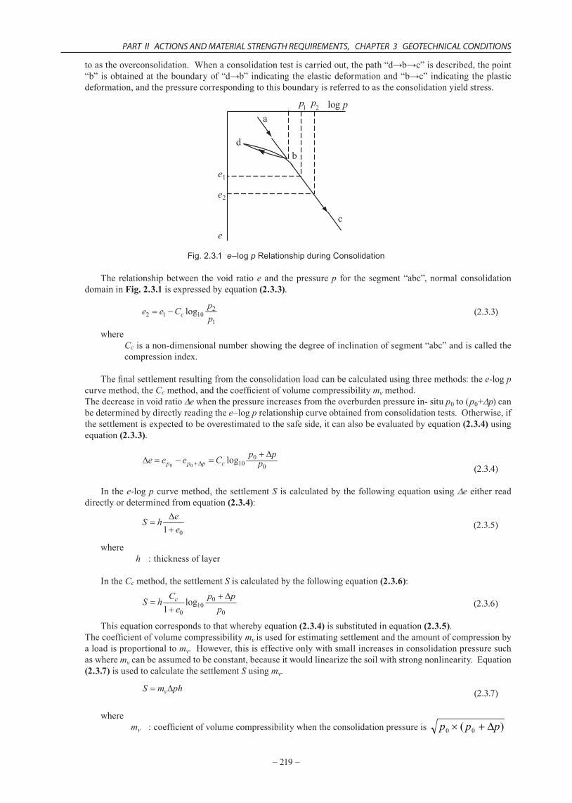
Whenthepermeablelayerexistatbothsidesofthecohesivesoillayer,themaximumdrainagedistanceH*isthesameasH.However,whenthepermeablelayeronlyexistsononeside,H*isequalto2H.ThedegreeofconsolidationateachdepthisshownbytheconsolidationisochronesinFig. 2.3.3.Furthermore,Fig. 2.3.4 shows
PART II ACTIONS AND MATERIAL STRENGTH REQUIREMENTS, CHAPTER 3 GEOTECHNICAL CONDITIONS
–221–
thetheoreticalrelationshipbetweentheaveragedegreeofconsolidationandthetimefactor.
0
0.5
1
1.5
2.00 0.1 0.2 0.3 0.4 0.5 0.6 0.7 0.8 0.9 1.0
H―Z
Degree of consolidation Uz
=0
T v
=0.05
0.10 0.15 0.200.30
0.400.50
0.60
0.70
0.80 0.848
0.90
Tv
Fig. 2.3.3 Consolidation Isochrones
0
20
40
60
80
100 0 0.1 0.2 0.5 0.6 0.7 0.8 0.9
u
u u u
u u uuii = = +
0
0
1
1
2
2
2H
H z-
0.3 0.4
H
Ave
rage
deg
ree
of c
onso
lidat
ion U
(%)
Time factor Tv
Fig. 2.3.4 Theoretical Relationship between Average Degree of Consolidation and Time Factor
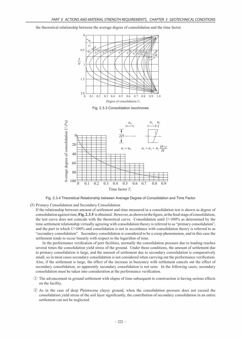
(5)PrimaryConsolidationandSecondaryConsolidationIftherelationshipbetweenamountofsettlementandtimemeasuredinaconsolidationtestisshownasdegreeofconsolidationagainsttime,Fig. 2.3.5 isobtained.However,asshowninthefigure,atthefinalstageofconsolidation,thetestcurvedoesnotcoincidewiththetheoreticalcurve.ConsolidationuntilU=100%asdeterminedbythetimesettlementrelationshipvirtuallyagreeingwithconsolidationtheoryisreferredtoas“primaryconsolidation”,andthepartinwhichU>100%andconsolidationisnotinaccordancewithconsolidationtheoryisreferredtoas“secondaryconsolidation”.Secondaryconsolidationisconsideredtobeacreepphenomenon,andinthiscasethesettlementtendstooccurlinearlywithrespecttothelogarithmoftime. Intheperformanceverificationofportfacilities,normallytheconsolidationpressureduetoloadingreachesseveraltimestheconsolidationyieldstressoftheground.Undertheseconditions,theamountofsettlementduetoprimaryconsolidationislarge,andtheamountofsettlementduetosecondaryconsolidationiscomparativelysmall,soinmostcasessecondaryconsolidationisnotconsideredwhencarryingouttheperformanceverification.Also,if thesettlementislarge,theeffectoftheincreaseinbuoyancywithsettlementcancelsouttheeffectofsecondaryconsolidation,soapparentlysecondaryconsolidationisnotseen.Inthefollowingcases,secondaryconsolidationmustbetakenintoconsiderationattheperformanceverification.
① Theadvancementingroundsettlementwithelapseoftimesubsequenttoconstructionishavingseriouseffectsonthefacility.
② As in the case of deep Pleistocene clayey ground, when the consolidation pressure does not exceed theconsolidationyieldstressofthesoillayersignificantly,thecontributionofsecondaryconsolidationinanentiresettlementcannotbeneglected.
–222–
TECHNICAL STANDARDS AND COMMENTARIES FOR PORT AND HARBOUR FACILITIES IN JAPAN
0
2040
6080
100120
t100
Theoretical curve
Experimental curveU = 100%
Secondaryconsolidation
Ave
rage
deg
ree
of c
onso
lidat
ion U
(%)
Primaryconsolidation
Fig. 2.3.5 Primary Consolidation and Secondary Consolidation
(6)ConsolidationSettlementofVerySoftCohesiveSoilsWhen the landfill iscarriedoutwithdredgingordisposedsludge, it isnecessary topredict theconsolidationsettlementofextremelysoftdeposits.Mikasa’s8)consolidationtheorywhichtakesintoaccounttheeffectofselfweightofclaylayerandthechangesinlayerthicknessduringconsolidationcanbeappliedtoanalyzethisproblem..Inthiscase,theamountandspeedofsettlementcannotbedeterminedanalytically;itmustbecalculatedwiththefinitedifferentialmethod. Whenthereductioninthicknessofalayerduetosettlementcomparedwiththeoriginalthicknessissolargethat it cannotbe ignored, the errors in thenormal consolidation settlement calculationmethodbecome large.Forexample,ifthereductioninthelayerthicknessis10to50%,thedifferencebetweenthenormalcalculationmethodandacalculationthattakesintoconsiderationtheeffectofthechangeinlayerthicknessisintheregion3to30%.Also,theeffectofdeadweightislargestafterallowingtostandafterdredgingandfilling,andastheloadincreases,theeffectisreducedrelatively.Forloadingthatistwiceormoretheaverageownweightofaweaklayer,theeffectofselfweightbecomesverysmall,andcanbevirtuallyignored. Inordertoestimatetheconsolidationparametersofverysoftcohesivesoil,thereisaconstantrateofstrainconsolidationtestinwhichdisplacementiscontinuouslyappliedasstipulatedinJISA1227Test Method for One-dimensional Consolidation Properties of Soils using Constant Rate of Strain Loading. Forcohesivesoilswithalargeagingeffect,orforcohesivesoilsofwhichsettlementcanbesuddenlyseenaftertheconsolidationyieldstress,theconstantrateofstrainconsolidationtestfromwhichacontinuouse–logpcurvecanbeobtainedisaveryusefulmethodforobtaining theconsolidationyieldstress9) However, thee–logpcurve isstronglyaffectedbythestrainrate,andthee–logpcurveobtainedfromthistestisnormallygreatlyshiftedtothelargeconsolidationpressuresidecomparedwiththee–logpcurveobtainedfromanicrementalloadingconsolidationtestasstipulatedinJISA1217.Thereforeitisnecessarytobeawarethattheconsolidationyieldstressbecomeslarger.
(7)CorrelationbetweentheCompressionandConsolidationCoefficientsandthePhysicalPropertiesOfallthesoiltests,theconsolidationtestrequiresthelongestamountoftime.Iftheresultsofconsolidationtestcanbeestimatedfromphysical test results,whichrequireonlydisturbedtestsamples,andisacomparativelysimpletestmethod,andmoreoverwhoseresultscanbequicklyobtained,thiswouldbeveryuseful.Skemptonhasproposedthecorrelationequation (2.3.10)astherelationshipbetweenthecompressionindexCcandtheliquidlimitwL.
(2.3.10)
Equation(2.3.10)isapplicabletoclaythatisre-moldedandre-consolidatedinthelaboratory,oryoungclaygroundformedbyartificialfilling,butittendstoeitheroverorunderestimatethecompressioncharacteristicsofnaturallydepositedclays. The reason why natural cohesive soil grounds have larger compression index values than young clay isbecauseintheprocessofsedimentationwhichoccursovermanyyears,astructureisformedduetoagingeffectssuchascementation. Whenthisstructure isdestroyedasaresultof theconsolidationpressureexceedingtheconsolidationyieldstress,highcompressibilityisdemonstrated.
PART II ACTIONS AND MATERIAL STRENGTH REQUIREMENTS, CHAPTER 3 GEOTECHNICAL CONDITIONS
–223–
2.3.3 Shear Characteristics
(1)Theshearstrengthparametersofsoilaredeterminedbyclassifyingsoilintosandysoilandcohesivesoil.Theshearstrengthofsandysoilisdeterminedunderdrainedconditions,whiletheshearstrengthforcohesivesoilisdeterminedunderundrainedconditions.
(2)Ingeneral,thehydraulicconductivityofsandysoilis103–105timesthatofcohesivesoil.Forsandysoillayer,theexcesswaterinporesisconsideredtobecompletelydrainedduringconstruction.Forcohesivesoillayer,ontheotherhand,almostnodrainageisexpectedduringconstructionbecausethehydraulicconductivityissignificantlylow.Thusinmanycasesforsandysoillayertheshearstrengthisevaluatedusingtheangleofshearresistanceindrainedcondition D andthecohesionindrainedconditioncD.BecausethevalueofcD isusuallyverysmall,practicallycD isignoredandonly D isusedasthestrengthparameter. Inthecaseofsaturatedcohesivesoillayer,theshearstrengthofthelayerundergoesalmostnochangebetweenbeforeandafterconstruction,asthedrainagecannottakeplaceduringconstruction.Theundrainedshearstrengthbeforeconstructionisthereforeusedasthestrengthparameter.Forintermediatesoilthathasthepermeabilitysomewherebetweenthoseofsandysoilandcohesivesoil,thesoilshouldbeviewedassandysoilorcohesivesoilbasedonthecoefficientofpermeabilityandconstructionconditions.
(3)ConsiderationsonShearStrengthTheshearstrengthτ fofasoilisgenerallyexpressedbythefollowingequation.
(2.3.11)where
τf :shearstrength c :cohesionorapparentcohesion :angleofshearresistance(°) σ :normalstressontheshearsurface
Whenastressisappliedtoasoil,thestressactingontheskeletalstructureofthesoilparticles,referredtoastheeffectivestress,andtheporewaterpressure,)bothchange.Ifthetotalstressappliedtothesoildenotesσ,theeffectivestressdenotesσ',andtheporewaterpressuredenotesu,thefollowingrelationshipcanbeestablished.
(2.3.12)
(2.3.13)
Inequation (2.3.11), thestrengthconstantssuchascand ,varydependingon theconditionsduring thesheartests,buttheconditionthathasthegreatesteffectisthedrainageconditionofthesoil.Becausesoilhasthetendencyofchangingvolumeswhichisknownas“dilatancy”whilebeingsheared,shearstrengthofsoilisgreatlydependentuponwhetheravolumechangetakesplaceduringtheshearornot.Thedrainageconditionisclassifiedintothefollowingthreecategoriesanddifferentstrengthparametersareusedforeachcase:
① Unconsolidated,Undrainedcondition(UUcondition)
② Consolidated,Undrainedcondition(CUcondition)
③ Consolidated,Drainedcondition(CDcondition)
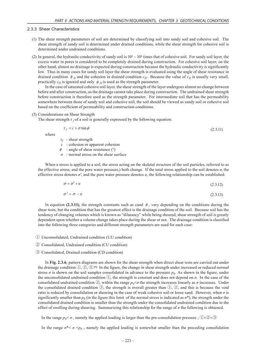
InFig. 2.3.6,patterndiagramsareshownfortheshearstrengthwhendirectsheartestsarecarriedoutunderthedrainagecondition①,②,③.10)Inthefigure,thechangeinshearstrengthunderincreasedorreducednormalstressσ isshownonthesoilsamplesconsolidatedinadvancetothepressurep0.Asshowninthefigure,undertheunconsolidatedundrainedcondition①,thestrengthisconstantanddoesnotdependonσ.Inthecaseoftheconsolidatedundrainedcondition②,withintherangep0<σthestrengthincreaseslinearlyasσincreases.Undertheconsolidateddrainedcondition③, thestrength isoverallgreater than①,②,and this isbecause thevoidratioisreducedbyconsolidationorshearinginthecaseofweakcohesivesoilorloosesand.However,whenσissignificantlysmallerthanp0(inthefigurethislimitofthenormalstressisindicatedasσ*),thestrengthundertheconsolidateddrainedconditionissmallerthanthestrengthundertheconsolidatedundrainedconditionduetotheeffectofswellingduringshearing.Summarizingthisrelationshipfortherangeofσthefollowingisobtained.
Intherangep0<σ , namelytheappliedloadingislargerthanthepre-consolidationpressure;①<②<③
In the rangeσ*<σ <p0 , namely the applied loading is somewhat smaller than thepreceding consolidation
–224–
TECHNICAL STANDARDS AND COMMENTARIES FOR PORT AND HARBOUR FACILITIES IN JAPAN
pressure;②<①<③or②<③<①Intherangeσ<σ*,namelytheappliedloadingissignificantlysmallerthantheprecedingconsolidationpressure;③<②<①
Fig. 2.3.6 Relationship between Drainage Conditions and Shear Strength
Theshearstrengthusedfortheperformanceverificationofgroundshouldbetheshearstrengthforthemostdangerousdrainageconditionsexpectedunderthegivenload.Thedrainageconditionandshearstrengtharethenasinthefollowing:
(a)Whenloadingtakesplacerapidlyonthecohesivesoilground:Becauseconsolidationprogressesandshearstrengthincreaseswiththeelapseoftime,themostdangeroustimewillbeimmediatelyaftertheloadingwhenalmostnodrainagehasoccurred.Thisiscalledtheshort-periodstabilityproblem.Theshearstrengthτfatthistimeistheshearstrengthcu thatisdeterminedfromunconsolidatedundrained(UU)testsusingthesamplebeforeloading.Theparametercu (undrainedshearstrength) isalsocalled theapparentcohesion,andtheanalysisusingcu isalsocalled the“ =0method”.Constructionsofseawallsorbreakwaterswithoutexcavation,landfill,andembankmentsonsoftcohesivesoilgroundfallinthiscategory.
(b)Whengroundpermeability is largeorwhendrainagefromconsolidated layer isalmostcompletedduringconstructionperiodbecausetheloadingiscarriedoutveryslowly: Becausedrainagefromthelayeroccurssimultaneouslywith loadingandanincreaseinstrengthof thelayer is expectedalongwith the loading, theperformanceverificationof structures shouldbecarriedoutusing cD and D determinedunderconsolidatedanddrained(CD)conditions.Constructionsofseawallsorbreakwaters,landfillandembankmentsonsandysoilbelongtothiscategory.
(c)Whenthehydraulicconductivityofthegroundispoorandtheloadisremovedtodecreasethenormalstressσontheshearplane: Inthiscase,themostdangeroussituationisafteralongtimehaselapsed,whenthesoilabsorbswater,expands,andlosesitsshearstrength,thisiscalledthelong-termstabilityproblem.AsshowninFig. 2.3.6,undrained shear strength becomes the lowest after water absorption and soil expansion when the over-consolidationratioissmall,inotherwords,σisalittlelessthanp0.Inthissituation,therefore,thecu valueshould be usedwith consideration of soil swelling. Earth retaining and excavation in clayey ground orremovalofpreloadingoncohesivesoilgroundbelongstothiscategory.Ontheotherhand,inthecaseofheavilyover-consolidatedgroundwhereσisverysmallcomparedtop0,theparameterscD and D areusedforperformanceverificationbecausetheshearstrengthunderconsolidated,drainedconditionisthesmallest.Usually,thisoftenappliestocaseswherecutearthmethodsareemployedbutitalsoappliestoconstructionworksincoastalareassuchasworkstodeeperquaywalldepthanddredgingworksonseabedsoil. In almost all cases for normal construction conditionsof port facilities, theundrained strength inUUconditionsof(a)isusedintheperformanceverificationforcohesivesoilsandthestrengthparameterintheCDconditionsof(b)isusedforsandysoils.Thefollowingequationsshowthestrengthcalculationmethodsrespectively:
1) Forcohesivesoilwiththesandcontentislessthan50%
(2.3.14)
PART II ACTIONS AND MATERIAL STRENGTH REQUIREMENTS, CHAPTER 3 GEOTECHNICAL CONDITIONS
–225–
whereτ:shearstrengthcu:undrainedshearstrength
2) Forsandysoilwiththesandcontentishigherthan80%
(2.3.15)where
τ :shearstrength σ :normalstresstoshearplane u :hydraulicpressureatthesite D :angleofshearresistancefordrainedconditions(º)
Furthermore, because soil with a sand fraction ranging from 50% – 80% displays intermediatecharacteristicsbetweensandysoilandcohesivesoil,itiscalledtheintermediatesoil.Theevaluationofshearstrengthofintermediatesoilisdifficultcomparedwiththatofsandysoilorcohesivesoil.Hence,theshearstrengthforsuchsoilshouldbeevaluatedcarefullybyreferringtothemostrecentresearchresults.Withrespecttointermediatesoilthatcanbetreatedascohesivesoil,itispreferabletoutilizeresultsoftriaxialCUtestsetc.ratherthanevaluateshearstrengthfromunconfinedcompressivestrength.
(4)ShearStrengthofSandBecausesandysoilhashighhydraulicconductivityandisregardedincompletelydrainedcondition,theshearstrengthofsandisrepresentedbyequation(2.3.15).Theangleofshearresistance D fordrainedconditionscanbedeterminedusingatriaxialCDtestunderconsolidatedanddrainedcondition.Becausethevalueof D becomeslargewhensand’svoidratiobecomessmallanditsdensitybecomeshigh,thevoidratioe0in-situshouldbeaccuratelydetermined.Therefore,itisbesttotakeandtestanundisturbedsample.Althoughthe D valuesofsandwiththesamedensitywillvaryalittlewiththeshearconditions,thevalueof D determinedbyatriaxialCDtest,whichisconductedwiththeconsolidationpressurecorrespondingtodesignconditionswithundisturbedsample, canbeused as thedesignparameter for stability analysis. However, in the caseofbearing capacityproblemforfoundation,whichismuchinfluencedbyprogressivefailure,thebearingcapacityisover-estimatedinsomecasesifthevalueof D determinedbyatriaxialCDtestisdirectlyusedasthedesignparameter. Comparedwiththecaseofcohesivesoil,samplingofundisturbedsandsamplesistechnicallydifficultandalsoveryexpensive.ThisisthereasonthattheshearstrengthforsandysoilisfrequentlydeterminedfromtheN-valueofstandardpenetrationtestratherthanfromalaboratorysoiltest.Fortheequationtodetermine DfromN-values,referto2.3.4 (4) Angle of shear resistance of sandy ground.
(5)ShearStrengthofCohesiveSoilHere, soil ofwhich the clay and silt fraction by percentage is greater than 50% is regarded as cohesive soil.Thereareseveralmethods,aspresentedbelow, todetermine theundrainedshearstrengthcu ofcohesivesoil.Anappropriatemethodshouldbechosen inconsiderationof such factorsas thepast experiences, the subsoilcharacteristicsandtheimportanceofthestructures.
① qu method:Thismethodusestheaveragevalueofunconfinedcompressivestrengthdeterminedfromundisturbedsamples.Theundrainedshearstrengthcu usedfortheperformanceverificationisgivenbythefollowingequation:
(2.3.16)
Inthisequation, uq istheaveragevalueofunconfinedcompressivestrength.Inunconfinedcompressiontests,confiningpressureisnotappliedonthetestsampleandtherefore, thestrengthresultobtainedmayberemarkablysmallduetodisturbanceofthesample.ApplicationisparticularlydifficultonclayeysoilsampledfromdepthsuchasstiffPleistoceneclayeysoilinwhichcrackscanappeareasily.Cautionisalsoneededforapplicationonintermediatesoilwithhighsandcontentaseffectivestressmaynotbemaintainedinthetestsampleandconsequently,aremarkablysmallshearstrengthmaybeobtained.Inthiscase,itispreferabletoemployothertestmethodssuchastriaxialtestordirectsheartest.
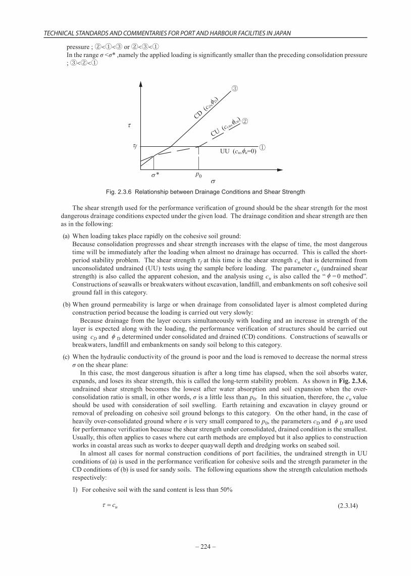
②Methodofusingstrengthbytriaxialteststakinginitialstressandanisotropyintoconsideration:Considerthestabilityanalysisofaembankmentontheclayeygroundusingacircularslip,asshowninFig. 2.3.7.Directlybelowtheembankmentshearingiscausedbytheincreaseinverticalstress,soitispossibletoevaluatetheshearstrengthcorrespondingtothisbythetriaxialconsolidatedundrainedcompressiontest(CUCtest),althoughstrictlyspeakingtherearedifferencesintheplanestrainandaxialsymmetry.Ontheotherhand,shearingoccursattheendpointofthecirculararc,inotherwordsnearthebaseoftheslope,duetotheincreaseinhorizontalstress,soitispossibletoevaluatethisbythetriaxialconsolidatedundrainedextensiontest(CUE).
–226–
TECHNICAL STANDARDS AND COMMENTARIES FOR PORT AND HARBOUR FACILITIES IN JAPAN
Ofcourse,therearedifferencesintheplanestrainandaxialsymmetry,andthereisthemajordifferencethatincontrasttothetriaxialextensiontestinwhichtheaxialforcereduces,inthefailureofanembankmentthehorizontalstressincreases.Nearthebottomofthecirculararc,thedeformationmodeisnotcompressionnorextension.,butvirtuallyhorizontalshearingisproduced.Therefore,itispossibletoevaluatethisbyadirectsheartestorasimplesheartest. Theshearstrengthsu*usedintheperformanceverificationmaybetheaveragevalueoftheshearstrengthsucobtainedfromacompressiontestandtheshearstrengthsueobtainedfromanextensiontestasgivenbythefollowingequation
(2.3.17)
orthedirectshearstrengthsusmaybeusedastherepresentativevalue.
usu ss =*
Formostsoils,thetriaxialextensionstrengthsueisabout70%ofthetriaxialcompressionstrengthsuc.
Triaxialextension
sue suc
sus
Triaxialcompression
Box shear
Fig. 2.3.7 Stability Problem and Strength Anisotropy for an Embankment Constructed on a Clayey Ground
Disturbanceofatestspecimenduringsamplingisinevitabletoacertainextent,evenifeffortsaremadetominimizeit.Also,ithasbeensaidforalongtimethattheunconfinedcompressiontestislackinginreliability,but the performance verification methods are frequently based on them, as in the present situation othermethodscannotbeadopted.Asamethodofdeterminingtheundrainedshearstrength,themethodknownasthe“recompressionmethod”11)issaidtobethemostreliableamongthetestmethodscurrentlyproposed.Thismethodisbasedonthethinkingthatbyreproducingthesamestressstateasthesampledtestspecimenintheoriginallocation,theeffectofdisturbanceinthetestspecimencanbemadesmallerbyconsolidation. Elementswithin a ground are subject to the vertical overburden effective stressσ'v0, and the horizontalearthpressureatrestσ'h0(=K0σ'v0).Asampledtestspecimenhaszerostressunderatmosphericpressure,andanisotropicresidualeffectivestressduetosuctionremainstoacertainextent.However,byconsolidationtoσ'1=σ'v0,σ'3=K0σ'v0intriaxialtestapparatus,undrainedsheartestscanbecarriedoutwiththesameeffectivestressstateastheoriginalpositionreproduced.Theeffectiveoverburdenpressureσ'v0canbecalculatedfromtheunitweightofthesampledtestspecimens.However,aproblematthisstageishowtoobtainthecoefficientofearthpressureK0.Severalmethodsforobtainingitfromin-situtestshavebeenproposed,butitcanalsobeobtainedfromalaboratorybyaK0consolidationtestusingatriaxialcell.12)Here,theK0consolidationtestisatestinwhichthecellpressureσ3iscontrolledsothatthecross-sectionalareaofthetestspecimendoesnotchangewhentheaxialpressureσ1ortheaxialstrainε1increases.However,K0obtainedbythismethodisK0forthenormallyconsolidatedstate,frequentlyexpressedasK0NC,soitisnecessarytobeawarethatitisnottheK0forsoilwiththeagingeffectasinarealground.InJapaneseclays,K0undernormallyconsolidatedconditionsismostlyintherange0.45to0.55. Therecompressionmethodisalsopossiblewiththedirectsheartest.Inthiscase,thechangeinthediameterofthetestspecimenisconstrainedbytheshearring,sobysimplymakingtheconsolidationpressureequaltotheeffectiveoverburdenpressureσ'v0,thereisnoparticularneedtobeawareofK0.Althoughtheundrainedshearstrength(qu/2)obtainedfromaunconfinedcompressiontesthasalargeamountofvariation,theaveragevalueisvirtuallythesameastheaveragevaluevalueofsucandsueoftheundrainedshearstrengthobtainedfromtriaxialcompressionandextensiontestsbytherecompressionmethodwithconsolidationofσ'v0andK0σ'v0,which iscapableofreproducing thesamestressstateas the testspecimenin theoriginallocation.Thereliabilityofthetestresultsusingtriaxialcompressionandextensiontestsbytherecompressionmethodwhosemechanicalbasisisclearer,isslightlyhigherthanthatoftheunconfinedcompressiontests.Insection2.1 Estimation of Ground Constants,itisexpectedthattriaxialtests,fromwhichresultswithsmall
PART II ACTIONS AND MATERIAL STRENGTH REQUIREMENTS, CHAPTER 3 GEOTECHNICAL CONDITIONS
–227–
variationcanbeobtained,arepreferablefortheperformanceverification.
③Methodusingstrengthfromadirectsheartest:ThismethodusesthestrengthτDS determinedbyadirectsheartestafterundisturbedsampleisconsolidatedone-dimensionallyunderin-situeffectiveoverburdenpressure.Thedirectsheartestcanbeconductedaccordingto theJGS 0560 Method for Consolidation parameters Pressure Direct Direct shear test on Soilof theGeotechnicalSocietyofJapan.Theundrainedshearstrengthcu usedfortheperformanceverificationisgivenbythefollowingequation:
(2.3.18)
Inthisequation,0.85isacorrectionfactorrelatedtoshearrateeffect.Themeasuredvalueshavethereforeundergoneprimaryprocessingtoarriveatthederivativevalues.
④Methodscombiningunconfinedcompressivestrengthandstrengthfromtriaxialcompressiontests:Oneproblemwiththequ methodisthatthetest’sreliabilityislowinsoilwithnopastrecords,becausethetestissubjecttotheinfluenceofdisturbanceduringsampling.Toresolvethisproblem,acombinationmethodcanbeusedtodeterminethestrengthbycomparingthequ ofundisturbedsampleswiththestrengthfromatriaxialCUtestandevaluatingthequalityofthesample.Inthismethod,thesampleisisotropicallyconsolidatedbyin-situmeaneffectivestressof2σ'v0/3whenK0=0.5,afterwhichtriaxialCUtestisperformedinundrainedcompressioncondition.Theundrainedshearstrengththusobtainedmustbeempiricallycorrectedbymultiplying0.75.Inotherwords,asisthecasewiththedirectsheartest,forthistriaxialtest,measuredvaluesmustundergoprimaryprocessingtoarriveatthederivativevalues.Thismethodisusedfornaturalsoilgroundandcannotbeappliedtounconsolidatedreclaimedground.Formoredetailsseethereferences13)and14).
⑤Methodfordeterminingundrainedshearstrengthfromanin-situvanesheartest:Avanesheartestisconductedasdescribedin1.3 Selection of Investigation Methods.Theaveragevalueoftheobtainedshearstrengthcu(v) canbeusedintheperformanceverificationastheundrainedshearstrengthcu 15).Anin-situvanesheartestcanbecarriedoutrathereasilywithmobilityatafieldsite.Thetestisabletodeterminetheshearstrengthforverysoftclayforwhichanunconfinedcompressiontestcannotbeperformedduetothedifficultyinmakingaspecimenfreestanding.Itcanthusbeapplied,forexample,totheconstructionmanagementwheresoilisbeingimprovedusingverticaldrains.Althoughthetestmethodandprinciplearesimple,attentionmustbegiventotheeffectoffrictionontherod.Waysofreducingthefrictionandcalibratingitseffectneedtobedevised. Eachmethodhasitsowncharacteristics,whichmustbedulyconsideredinordertoselectthemostappropriateone.Theundrained shear strengthcu of cohesive soils increases as consolidationprogresses, and thehigher theconsolidationloadthelargerthecuafterconsolidation.Therefore,theconsolidationpressureincreaseswithdepthastheoverburdenpressureincreases,sonormallythecuofaclaygroundincreaseswithdepth,andthedistributionofundrainedshearstrengthused in theperformanceverification is frequentlyexpressedby thefollowingequation.
(2.3.19)
where cu :undrainedshearstrengthatdepthzfromthesurfaceoftheclaylayer cu0 :undrainedshearstrengthatsurfaceoftheclaylayer k :rateofincreaseofcuwithdepthz z :depthfromthesurfaceoftheclaylayer
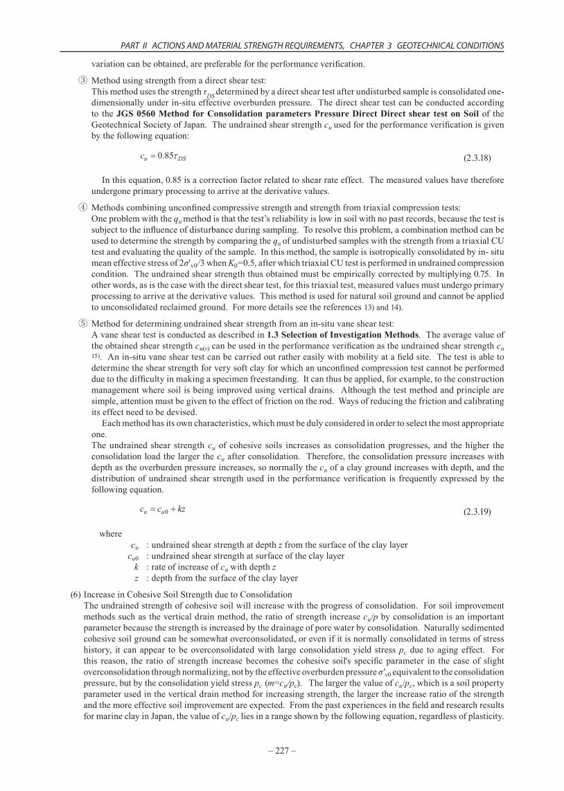
(6)IncreaseinCohesiveSoilStrengthduetoConsolidationTheundrainedstrengthofcohesivesoilwillincreasewiththeprogressofconsolidation.Forsoilimprovementmethodssuchastheverticaldrainmethod,theratioofstrengthincreasecu/p byconsolidationisanimportantparameterbecausethestrengthisincreasedbythedrainageofporewaterbyconsolidation.Naturallysedimentedcohesivesoilgroundcanbesomewhatoverconsolidated,orevenifitisnormallyconsolidatedintermsofstresshistory, it canappear tobeoverconsolidatedwith largeconsolidationyield stresspc due toagingeffect. Forthis reason, the ratio of strength increase becomes the cohesive soil's specific parameter in the case of slightoverconsolidationthroughnormalizing,notbytheeffectiveoverburdenpressureσ'v0equivalenttotheconsolidationpressure,butbytheconsolidationyieldstresspc (m=cu/pc).Thelargerthevalueofcu/pc,whichisasoilpropertyparameterusedintheverticaldrainmethodforincreasingstrength,thelargertheincreaseratioofthestrengthandthemoreeffectivesoilimprovementareexpected.FromthepastexperiencesinthefieldandresearchresultsformarineclayinJapan,thevalueofcu/pc liesinarangeshownbythefollowingequation,regardlessofplasticity.
–228–
TECHNICAL STANDARDS AND COMMENTARIES FOR PORT AND HARBOUR FACILITIES IN JAPAN
(2.3.20)
InviewofthefactthattheoverconsolidationratioOCRofnaturallysedimentedcohesivesoilisnormallyintherangefrom1.0to1.5,andσ'v0=pc/OCR,therefore,thedatainFig. 2.3.8 15)providessubstantiationforequation (2.3.20).
Triaxial compressionDirect shearTriaxial extension
0.4
0.3
0.2
0.1
00 4020 60 80 100
Plasticity Index Ip
c u /
σ'v0
Fig. 2.3.8 Relationship between Plasticity Index and cu/σ'v0
(7)DecreaseofStrengthofCohesiveSoilsduetoSwellingIfpartoftheloadisremovedafterconsolidation,cohesivesoilsabsorbwaterandswellwithtime,whichcausesthecu toreduce. Inaddition,thetimerequiredforswellingisconsiderablyshorterthanthetimerequiredforconsolidation.Thedrainageconditionsofthiscasecorrespondtotheleftof③asshowninFig. 2.3.6,soitisnecessarytoevaluatethelikelystrengthdecreaseafterswelling.16)Specifically,theremovalofloadattheendofconsolidationinsoilimprovementworkssuchastheverticaldrainmethodorthepreloadmethod,excavationforearthretainingstructures,17)anddredgingtodeepertheseabottom,etc.,correspondtothissituation.
(8)StrengthofIntermediateSoilSoilwithasandcontentintherangeof50%-80%isintermediatesoilbetweensandysoilandcohesivesoil.10)Forthistypeofsoil,thehydraulicconductivityanddesignconditionsaretakenintoconsiderationtodeterminewhetherthesoilissandysoilorcohesivesoil.Thentheshearstrengthisdeterminedaccordingly.Forintermediatesoilwithalargesandfractionorwithcoralgravel,thehydraulicconductivitydeterminedfromanincrementalloadingoedometertestgenerallygivesanunderestimatedvalue,becauseofthelimitationsoftestconditions.Itispreferablenotonlytoimprovethetestprocedure,butalsotoconductanin-situpermeabilitytestoranelectricalconetesttodeterminethehydraulicconductivity.19) Whenthehydraulicconductivitydeterminedbythiskindofprocedureisgreaterthan10-4cm/s,thegroundisregardedpermeable.Hence,thevalueof D determinedfromanelectricalconepenetrationresistanceoratriaxialCDtestcanbeusedasdesignparametersregarding cD =0.AccordingtoexperienceininvestigatingthepropertiesofintermediatesoilsinJapan,thevalueof D isgreaterthan30ºinmanycases.20),21),22) Whenthehydraulicconductivityislessthan10-4cm/s,theperformanceverificationoftheintermediatesoilshouldbeconductedasacohesivesoil.Becausetheinfluenceofstressreleaseduringsamplinginintermediatesoilismuchgreaterthanthatincohesivesoil,theshearstrengthdeterminedbyqu methodisunderestimated.Acorrectionmethodisusedforthestrengthofsuchintermediatesoilwithalargesandfractionbymeansofclayfractionandplasticityindex.23)However,itispreferablethatthecombinedmethodwithunconfinedcompressiontestand triaxialcompression testor thedirectshear testbeusedas themethodforevaluating thestrengthofintermediatesoil.24)
2.3.4 Interpretation Method for N Values
(1)Theangleofshearresistanceforsandysoilsiscalculatedusingthefollowingequationfromastandardpenetrationtestvalue.
(2.3.21)
where :angleofshearresistanceofsand(º)

PART II ACTIONS AND MATERIAL STRENGTH REQUIREMENTS, CHAPTER 3 GEOTECHNICAL CONDITIONS
–229–
N :standardpenetrationtestvalue σ'v0 :effectiveoverburdenpressure at thedepthwhere the standardpenetration test is performed
(kN/m2)
(2)RelationshipsbetweentheN-valueandmanysoilparametershavebeenestablishedbythedataatvarioussites.Whenusingtheserelationships,however,itisnecessarytoconsiderthebackgroundoftheirderivationandthegroundconditionsofthedataandtoconfirmtherangeoftheirapplicability.AscanbeseeninDunham’sequation,which has commonly been used formany years, the value of was determined directly from theN-valueswithoutconsideringtheeffectiveoverburdenpressureσ'v0.However,becausetherelativedensityDr varieswithσ'v0asseeninFig. 2.3.9,σ'v0mustbetakenintoconsiderationtodetermineDrfromanN-value.Thisconceptwasincorporatedinthejudgmentofliquefaction.Inthisjudgment,liquefactionresistanceisexaminedfromN65,theequivalentN-valueconvertedintoN-valuewheneffectiveoverburdenpressureσ'v0=65kN/m2.Similarly,itisknownthateveningroundswiththesame , theN-valueincreaseswiththeincreaseineffectiveoverburdenpressure.Therefore,theinfluenceofσ'v0mustbetakenintoaccountwhendetermining fromtheN-values.
0
10
20
30
40
50
40 600
80 100
'v0=200kN/m2
'v0=100kN/m2
'v0=100kN/m2
'v0=0
'v0=200kN/m2
N-v
alue
Relative density Dr (%)
σ'v0
: Terzaghi
: Gibbs, Holtz (dry sand, wet sand)
: Yanase (wet fine sand)
: " (saturated fine sand)
: effective overburden pressure
: Terzaghi
: Gibbs, Holtz (dry sand, wet sand)
: Yanase (wet fine sand)
: " (saturated fine sand)
: effective overburden pressure
Fig. 2.3.9 Influence of Effective Overburden Pressure and Relative Density on N-Values
(3)FactorsAffectingtheN-valuesThe factors that affectN-valuesmutually overlap, andmethods for quantitatively correcting for these factorshavenotyetbeenestablished.However,forunderstandingofN-values,theextentoftheeffectoftheimportantinfluencingfactorsisasfollows:
① DensityAsthedensity,relativedensity,ofthesubsoilincreases,inparticularforsandysoils,theN-valueincreases.
②WatercontentApartfromwellcompactedfinesandandsiltysoils,theN-valueincreasesintheorderofsaturatedsand,drysand,andwetsand.
③ EffectiveoverburdenpressureTheN-valueincreasesastheeffectiveoverburdenpressureincreases.
④ EffectofgroundwaterlevelAsthegroundwaterlevelfluctuates,theeffectiveoverburdenpressureandthedegreeofsaturationofthesoilvaries,sotheN-valuesvaryaccordingly.
⑤ OtherinfluencingfactorsTheN- value varies in accordancewith the soil particle shape, the grain size distribution, and themineralcompositionofthesoil.
–230–
TECHNICAL STANDARDS AND COMMENTARIES FOR PORT AND HARBOUR FACILITIES IN JAPAN
(4)AngleofShearResistanceofSandyGroundTheangleofshearresistance isanimportantconstantfor theperformanceverificationofgrounds,similartotheundrainedshearstrengthofclaysoils.However, isacomplexvaluethatisgovernedbymanyfactors,andeventhesamesoilwillnothaveaconstantvalue.Therefore,itisnecessarytoinvestigatesufficientlythebackground toestablishing theperformanceverificationmethods,suchaswhatconditionsareassumedin theperformanceverificationmethodsusing .
(5)N-valueofCohesiveSoilGroundComparedwithsandground,theN-valueofacohesivesoilissmall,anditsreliabilityislow.Accordingtopastexperienceandtestresults,ifthequis100kN/m2orlowerthemeasurementofN-valueisdifficult.Incohesivesoilswithquofthisvalue,whensoftcohesivesoilsarefoundbytakingtestspecimenswithastandardpenetrationtesttypesamplerduringapreliminaryinvestigation,orwhentestsarecarriedouttoknowthephysicalproperties,thishassignificance,butthestrengthandothermechanicalsubsoilconstantscannotbedeterminedfromtheN-valuesonly.InthecaseofaPleistoceneclaysoilwithhighstrength,thepastdepositionenvironmentandstresshistoryhaschangedseveraltimes,soevenwithinthesamestratumthepropertiesofthesoilarenotuniform,andanoverconsolidatedstatethatisunrelatedtothepresenteffectiveoverburdenpressureisfrequentlyfound.Therefore,theN-valuesandsoilpropertieschangegreatlywithonlysmallchangesinpositionordepth.Also,techniquesforsamplingstiffsoilsaredifficult,andcrackscaneasilybefirmedinthetestspecimens.InJapanthestrengthofstiffcohesivesoilisfrequentlyevaluatedusingthequvalue,butthequvalueisveryeasilyaffectedbythequalityofthetestspecimens.
2.4 Dynamic Analysis2.4.1 Dynamic Modulus of Deformation
(1)Forseismicresponseanalysis,anappropriatedynamicmodulusofdeformationofsoilsshallbedeterminedtoprescribetherelationshipbetweentheshearstressandshearstrainofsoil.
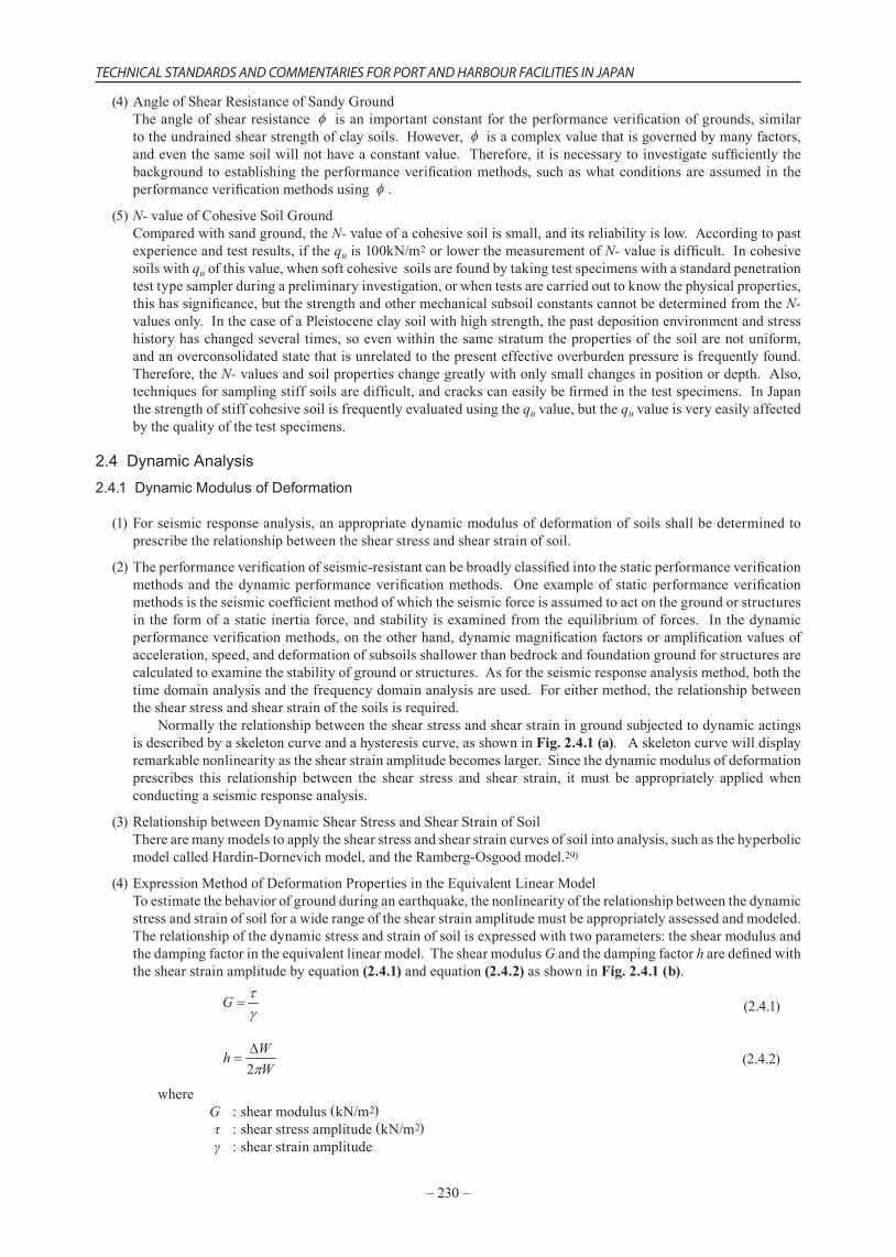
(2)Theperformanceverificationofseismic-resistantcanbebroadlyclassifiedintothestaticperformanceverificationmethodsand thedynamicperformanceverificationmethods. Oneexampleof staticperformanceverificationmethodsistheseismiccoefficientmethodofwhichtheseismicforceisassumedtoactonthegroundorstructuresintheformofastaticinertiaforce,andstabilityisexaminedfromtheequilibriumofforces. Inthedynamicperformanceverificationmethods,ontheotherhand,dynamicmagnificationfactorsoramplificationvaluesofacceleration,speed,anddeformationofsubsoilsshallowerthanbedrockandfoundationgroundforstructuresarecalculatedtoexaminethestabilityofgroundorstructures.Asfortheseismicresponseanalysismethod,boththetimedomainanalysisandthefrequencydomainanalysisareused.Foreithermethod,therelationshipbetweentheshearstressandshearstrainofthesoilsisrequired. Normallytherelationshipbetweentheshearstressandshearstrainingroundsubjectedtodynamicactingsisdescribedbyaskeletoncurveandahysteresiscurve,asshowninFig. 2.4.1 (a).Askeletoncurvewilldisplayremarkablenonlinearityastheshearstrainamplitudebecomeslarger.Sincethedynamicmodulusofdeformationprescribes this relationship between the shear stress and shear strain, itmust be appropriately appliedwhenconductingaseismicresponseanalysis.
(3)RelationshipbetweenDynamicShearStressandShearStrainofSoilTherearemanymodelstoapplytheshearstressandshearstraincurvesofsoilintoanalysis,suchasthehyperbolicmodelcalledHardin-Dornevichmodel,andtheRamberg-Osgoodmodel.29)
(4)ExpressionMethodofDeformationPropertiesintheEquivalentLinearModelToestimatethebehaviorofgroundduringanearthquake,thenonlinearityoftherelationshipbetweenthedynamicstressandstrainofsoilforawiderangeoftheshearstrainamplitudemustbeappropriatelyassessedandmodeled.Therelationshipofthedynamicstressandstrainofsoilisexpressedwithtwoparameters:theshearmodulusandthedampingfactorintheequivalentlinearmodel.TheshearmodulusG andthedampingfactorh aredefinedwiththeshearstrainamplitudebyequation(2.4.1)andequation(2.4.2)asshowninFig. 2.4.1 (b).
(2.4.1)
(2.4.2)
where G :shearmodulus(kN/m2) τ :shearstressamplitude(kN/m2) γ :shearstrainamplitude
PART II ACTIONS AND MATERIAL STRENGTH REQUIREMENTS, CHAPTER 3 GEOTECHNICAL CONDITIONS
–231–
h :dampingfactor W :strainenergy(kN/m2) W :dampingenergy(kN/m2)
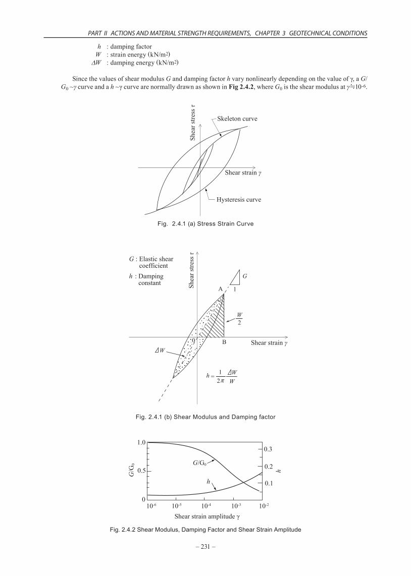
SincethevaluesofshearmodulusG anddampingfactorh varynonlinearlydependingonthevalueofγ,aG/ G0~γcurveandah ~γcurvearenormallydrawnasshowninFig 2.4.2,whereG0istheshearmodulusatγ≒10-6.
Hysteresis curve
Skeleton curve
Shear strain γ
Shea
r stre
ss τ
Fig. 2.4.1 (a) Stress Strain Curve
G : Elastic shear coefficienth : Damping constant
G
h
W
WW
A
B
1
2
0
21
-
-
W
-=
Shear strain γ
Shea
r stre
ss τ
Fig. 2.4.1 (b) Shear Modulus and Damping factor
1.0
0.5
0.3
0.2
0.1
010-510-6 10-4 10-210-3
G/G
0 G/G0
h
Shear strain amplitude γ
h
Fig. 2.4.2 Shear Modulus, Damping Factor and Shear Strain Amplitude
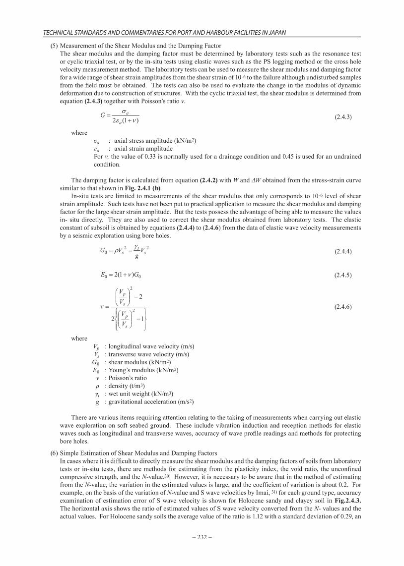
–232–
TECHNICAL STANDARDS AND COMMENTARIES FOR PORT AND HARBOUR FACILITIES IN JAPAN
(5)MeasurementoftheShearModulusandtheDampingFactorTheshearmodulusand thedampingfactormustbedeterminedby laboratory testssuchas theresonance testorcyclictriaxialtest,orbythein-situtestsusingelasticwavessuchasthePSloggingmethodorthecrossholevelocitymeasurementmethod.Thelaboratorytestscanbeusedtomeasuretheshearmodulusanddampingfactorforawiderangeofshearstrainamplitudesfromtheshearstrainof10-6tothefailurealthoughundisturbedsamplesfromthefieldmustbeobtained.Thetestscanalsobeusedtoevaluatethechangeinthemodulusofdynamicdeformationduetoconstructionofstructures.Withthecyclictriaxialtest,theshearmodulusisdeterminedfromequation (2.4.3)togetherwithPoisson’sratiov.
(2.4.3)
where σa :axialstressamplitude(kN/m2) εa :axialstrainamplitudeForv, thevalueof0.33isnormallyusedforadrainageconditionand0.45isusedforanundrainedcondition.
Thedampingfactoriscalculatedfromequation (2.4.2)withW and Wobtainedfromthestress-straincurvesimilartothatshowninFig. 2.4.1 (b). In-situtestsarelimitedtomeasurementsoftheshearmodulusthatonlycorrespondsto10-6levelofshearstrainamplitude.Suchtestshavenotbeenputtopracticalapplicationtomeasuretheshearmodulusanddampingfactorforthelargeshearstrainamplitude.Butthetestspossesstheadvantageofbeingabletomeasurethevaluesin-situdirectly. Theyarealsousedtocorrect theshearmodulusobtainedfromlaboratory tests. Theelasticconstantofsubsoilisobtainedbyequations (2.4.4)to(2.4.6)fromthedataofelasticwavevelocitymeasurementsbyaseismicexplorationusingboreholes.
(2.4.4)
(2.4.5)
(2.4.6)
where Vp :longitudinalwavevelocity(m/s) Vs :transversewavevelocity(m/s) G0 :shearmodulus(kN/m2) E0 :Young’smodulus(kN/m2) ν :Poisson’sratio ρ :density(t/m3) γt :wetunitweight(kN/m3) g :gravitationalacceleration(m/s2)
Therearevariousitemsrequiringattentionrelatingtothetakingofmeasurementswhencarryingoutelasticwaveexplorationonsoft seabedground. These includevibration inductionandreceptionmethods forelasticwavessuchaslongitudinalandtransversewaves,accuracyofwaveprofilereadingsandmethodsforprotectingboreholes.
(6)SimpleEstimationofShearModulusandDampingFactorsIncaseswhereitisdifficulttodirectlymeasuretheshearmodulusandthedampingfactorsofsoilsfromlaboratorytestsor in-situ tests, therearemethodsforestimatingfromtheplasticity index, thevoidratio, theunconfinedcompressivestrength,andtheN-value.30)However,itisnecessarytobeawarethatinthemethodofestimatingfromtheN-value,thevariationintheestimatedvaluesislarge,andthecoefficientofvariationisabout0.2.Forexample,onthebasisofthevariationofN-valueandSwavevelocitiesbyImai,31)foreachgroundtype,accuracyexaminationofestimationerrorofSwavevelocity isshownforHolocenesandyandclayeysoil inFig.2.4.3.ThehorizontalaxisshowstheratioofestimatedvaluesofSwavevelocityconvertedfromtheN-valuesandtheactualvalues.ForHolocenesandysoilstheaveragevalueoftheratiois1.12withastandarddeviationof0.29,an
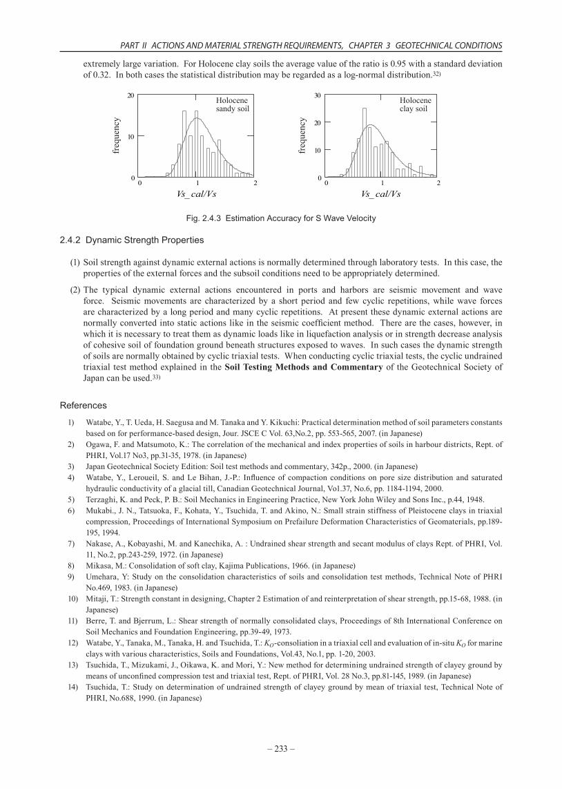
PART II ACTIONS AND MATERIAL STRENGTH REQUIREMENTS, CHAPTER 3 GEOTECHNICAL CONDITIONS
–233–
extremelylargevariation.ForHoloceneclaysoilstheaveragevalueoftheratiois0.95withastandarddeviationof0.32.Inbothcasesthestatisticaldistributionmayberegardedasalog-normaldistribution.32)
0 1 20
10
20
Vs_ cal/Vs Vs_ cal/Vs0 1 2
0
10
20
30
freq
uenc
yHolocenesandy soil
Holoceneclay soil
freq
uenc
y
Fig. 2.4.3 Estimation Accuracy for S Wave Velocity
2.4.2 Dynamic Strength Properties
(1)Soilstrengthagainstdynamicexternalactionsisnormallydeterminedthroughlaboratorytests.Inthiscase,thepropertiesoftheexternalforcesandthesubsoilconditionsneedtobeappropriatelydetermined.
(2)The typical dynamic external actions encountered in ports and harbors are seismic movement and waveforce. Seismicmovements are characterized by a short period and few cyclic repetitions,whilewave forcesarecharacterizedbyalongperiodandmanycyclicrepetitions.Atpresentthesedynamicexternalactionsarenormallyconvertedintostaticactionslikeintheseismiccoefficientmethod.Therearethecases,however,inwhichitisnecessarytotreatthemasdynamicloadslikeinliquefactionanalysisorinstrengthdecreaseanalysisofcohesivesoiloffoundationgroundbeneathstructuresexposedtowaves.Insuchcasesthedynamicstrengthofsoilsarenormallyobtainedbycyclictriaxialtests.Whenconductingcyclictriaxialtests,thecyclicundrainedtriaxial testmethodexplained in theSoil Testing Methods and Commentaryof theGeotechnicalSocietyofJapancanbeused.33)
References
1) Watabe,Y.,T.Ueda,H.SaegusaandM.TanakaandY.Kikuchi:Practicaldeterminationmethodofsoilparametersconstantsbasedonforperformance-baseddesign,Jour.JSCECVol.63,No.2,pp.553-565,2007.(inJapanese)
2) Ogawa,F.andMatsumoto,K.:Thecorrelationofthemechanicalandindexpropertiesofsoilsinharbourdistricts,Rept.ofPHRI,Vol.17No3,pp.31-35,1978.(inJapanese)
3) JapanGeotechnicalSocietyEdition:Soiltestmethodsandcommentary,342p.,2000.(inJapanese)4) Watabe,Y.,Leroueil,S. andLeBihan, J.-P.: Influenceof compaction conditionsonpore sizedistribution and saturated
hydraulicconductivityofaglacialtill,CanadianGeotechnicalJournal,Vo1.37,No.6,pp.1184-1194,2000.5) Terzaghi,K.andPeck,P.B.:SoilMechanicsinEngineeringPractice,NewYorkJohnWileyandSonsInc.,p.44,1948.6) Mukabi.,J.N.,Tatsuoka,F.,Kohata,Y.,Tsuchida,T.andAkino,N.:SmallstrainstiffnessofPleistoceneclaysintriaxial
compression,ProceedingsofInternationalSymposiumonPrefailureDeformationCharacteristicsofGeomaterials,pp.189-195,1994.
7) Nakase,A.,Kobayashi,M.andKanechika,A.:UndrainedshearstrengthandsecantmodulusofclaysRept.ofPHRI,Vol.11,No.2,pp.243-259,1972.(inJapanese)
8) Mikasa,M.:Consolidationofsoftclay,KajimaPublications,1966.(inJapanese)9) Umehara,Y:Studyon theconsolidationcharacteristicsofsoilsandconsolidation testmethods,TechnicalNoteofPHRI
No.469,1983.(inJapanese)10) Mitaji,T.:Strengthconstantindesigning,Chapter2Estimationofandreinterpretationofshearstrength,pp.15-68,1988.(in
Japanese)11) Berre,T.andBjerrum,L.:Shearstrengthofnormallyconsolidatedclays,Proceedingsof8thInternationalConferenceon
SoilMechanicsandFoundationEngineering,pp.39-49,1973.12) Watabe,Y.,Tanaka,M.,Tanaka,H.andTsuchida,T.:KO-consoliationinatriaxialcellandevaluationofin-situKOformarine
clayswithvariouscharacteristics,SoilsandFoundations,Vol.43,No.1,pp.1-20,2003.13) Tsuchida,T.,Mizukami,J.,Oikawa,K.andMori,Y.:Newmethodfordeterminingundrainedstrengthofclayeygroundby
meansofunconfinedcompressiontestandtriaxialtest,Rept.ofPHRI,Vol.28No.3,pp.81-145,1989.(inJapanese)14) Tsuchida,T.:Studyondeterminationofundrainedstrengthofclayeygroundbymeanof triaxial test,TechnicalNoteof
PHRI,No.688,1990.(inJapanese)
–234–
TECHNICAL STANDARDS AND COMMENTARIES FOR PORT AND HARBOUR FACILITIES IN JAPAN
15) Tanaka,H.andTanaka,M.:Determinationofundrainedshearstrengthofclayeygroundmeasuredbyvanesheartests,Rept.ofPHRI,Vol.33,No.4,pp.1-17,1994.(inJapanese)
16) Nakase,A.,KobayashiM.andKatsunoM.:Changeinshearstrengthofsaturatedclaysthroughconsolidationandrebound,Rept.ofPHRI,Vol.8,No.4,pp.103-143,1969.(inJapanese)
17) Tanaka,H.:Behaviorofbracedexcavationsinsoftground,TechnicalNoteofPHRI,No.734,p.21,1992.(inJapanese)18) Kurata,S.,Morishita,T.,Goto,K.,Suzuki,K.andFukazawa,K.:Studyonengineeringcharacteristicsofsand-claymixed
soil,Rept.ofTransportTechnicalResearchInstitute,Vol.11,No.9,pp.36,1961.(inJapanese)19) Tanaka,H.,Sakakibara,M.,Goto,K.,Suzuki,K.andFukazawa,K.:PropertiesofJapaneseNormallyConsolidatedmarine
claysobtainedfromstaticpiezoconepenetrationtest,Rept.ofPHRI,Vol.31,No.4,pp.61-92,1992.(inJapanese)20) Kobayashi,M., Tsuchida, T. and Kamei, Y.: Intermediate soil-Sand or clay?-Geotech-Note 2, Japanese Society of Soil
MechanicsandFoundation,1992.(inJapanese)21) Tsuchida,T.,Kobayashi,M.,Ifuku,S.andFukuda,I.:EngineeringpropertiesofcoralsoilsinJapanesesouthwesternislands,
InternationalConferenceonlimecontainingsoil,1988.(inJapanese)22) Tsuchida,T:Consolidationcompressionandpermeabilitycharacteristicofintermediatesoil,Tsuchi-to-Kiso,Vol.41,Japanese
GeotechnicalSociety,1993.(inJapanese)23) Nakase,A.,KatsunoM.andKobayashi,M.:Unconfinedcompressionstrengthofsoilsofintermediategradingbetweensand
andclay,Rept.ofPHRI,Vol.11No.4,1972.(inJapanese)24) Tanaka,H.,Tanaka,M.andTsuchida,T.:Strengtheningcharacteristicsofundisturbedintermediatesoil,Jour.JSCE,No.589/
III-42,pp.195-204,1998.(inJapanese)25) Iwasaki,T.:Problemsrelatedtostandardpenetrationtest,TheFoundationEngineering&Equipment,Vol.18,No.3pp.40-48,
1990.(inJapanese)26) Meyerhof,G.G.:Discussiononsoilpropertiesandtheirmeasurement,Discussion2,Proc.ofthe4thInternationalConference
onSoilMechanicsandFoundationEngineering,Vol.III,p.110,1957.27) Iai, S., Koizumi, K. and Tsuchida, H. : Affiliation a new criterion for assessing liquefaction potential using grain size
accumulationcurveandN-value,Rept.ofPHRI,Vol.25,No.3,pp.125-234,1986.(inJapanese)28) Meyerhof,G.G.:Compactionofsandsandbearingcapacityofpiles,ASCE,Vol.85,No.SM6,pp.l-29,1959.29) Ishihara,K:Fundamentalsofsoildynamics.KajimaPublishing,pp.7-34,1976.(inJapanese)30) CoastalDevelopmentInstituteofTechnology(CDIT):Handbookofcountermeasureagainstliquefactionofreclaimedland
(Revisededition),CDIT,pp.60-77,1997.(inJapanese)31) Imai,T.:PandSwavevelocitiesofthegroundinJapan,Proc.IXthICSMFE,1977.32) Nagao,T.etal.:ReliabilitydesignmethodagainstLevel1earthquakemotionofpiers,ProceedingofStructuralEng.Vol.52A,
2006.(inJapanese)33) JapaneseGeotechnicalSociety:Soiltestmethodsandcommentary,pp,421-450,1990(inJapanese)34) Ishihara,K.:FundamentalsofSoilDynamics.KajimaPublishing,pp.1-6,1976(inJapanese)35) JapaneseGeotechnicalSociety:Soiltestmethodsandcommentary,pp.421-457,1990.(inJapanese)36) CoastalDevelopmentInstituteofTechnology(CDIT):Handbookofcountermeasureagainstliquefactionofreclaimedland
(Revisededition),CDIT,pp.60-77,1997.(inJapanese)


![[chapter] [chapter] atiques](https://img.pdfslide.tips/doc/110x75/62ab0da599df7d685a5c7171/chapter-chapter-atiques.jpg)