Embed Size (px)
Citation preview
Comparison of angle-of-arrival characteristics at2.4GHz and 60GHz bands
Takuto Kurose, Satoru Kishimoto, and Minseok Kima)
Graduate School of Science and Technology, Niigata University,
8050 Ikarashi 2-no-cho, Nishi-ku, Niigata 950–2181, Japan
Abstract: For seamless communication in millimeter-wave (mm-wave)
transmission systems, the robustness against link blockage and user mobility
should be guaranteed. Cooperative joint network design over conventional
microwave bands and mm-wave bands is essential in future mm-wave
WLANs (e.g., IEEE 802.11ay) and 5G cellular networks, and hence under-
standing the discrepancy between the propagation properties at those fre-
quency bands is crucial. In this letter, the angle-of-arrival characteristics at
mm-wave band (60GHz) and microwave band (2.4GHz) in indoor environ-
ments are presented. From the measurement results, it was seen that the line-
of-sight and first-order reflected paths agree well each other, but diffraction
and scattering are observed only at microwave band. It was also shown that
the angular spreads at mm-wave band was about 25 degrees smaller than
those at microwave band.
Keywords: fast session transfer, millimeter wave, microwave, channel
sounding, angle-of-arrival, angle spread, antenna array
Classification: Antennas and Propagation
References
[1] “Channel models for 60GHz WLAN systems,” IEEE Document 802.11-09/0334r8, May 2010.
[2] “Channel models for IEEE 802.11ay,” IEEE Document 802.11-15/1150r2,Sept. 2015.
[3] A. Patra, L. Simić, and M. Petrova, “Design and experimental evaluation of a2.4GHz-AoA-enhanced beamsteering algorithm for IEEE 802.11ad mm-waveWLANs,” IEEE 18th International Symposium on A World of Wireless,Mobile and Multimedia Networks (WoWMoM), July 2017. DOI:10.1109/WoWMoM.2017.7974290
[4] S. Sur, I. Pefkianakis, X. Zhang, and K. Kim, “WiFi-assisted 60GHz wirelessnetworks,” The 23rd Annual International Conference on Mobile Computingand Networking, Snowbird, Utah, United States, Oct. 2017. DOI:10.1145/3117811.3117817
[5] C. Gustafson, F. Tufvesson, S. Wyne, K. Haneda, and A. F. Molisch,“Directional analysis of measured 60GHz indoor radio channels using SAGE,”IEEE 73rd Vehicular Technology Conference (VTC Spring), Yokohama, Japan,May 2011. DOI:10.1109/VETECS.2011.5956639
[6] J. Medbo, N. Seifi, and H. Asplund, “Frequency dependency of measured
© IEICE 2019DOI: 10.1587/comex.2019XBL0093Received June 10, 2019Accepted June 28, 2019Publicized July 16, 2019Copyedited October 1, 2019
404
IEICE Communications Express, Vol.8, No.10, 404–409
highly resolved directional propagation channel characteristics,” The 10thEuropean Conference on Antennas and Propagation (EuCAP), Oulu, Finland,May 2016.
[7] J. Medbo, H. Asplund, and J.-E. Berg, “60GHz channel directional character-ization using extreme size virtual antenna array,” IEEE 26th AnnualInternational Symposium on Personal, Indoor, and Mobile Radio Communi-cations (PIMRC), Hong Kong, China, Sept. 2015. DOI:10.1109/PIMRC.2015.7343290
[8] S. Kishimoto, M. Kim, D. He, and K. Guan, “Scattering process identificationand cluster analysis for millimeter-wave indoor channel model,” 2018International Symposium on Antennas and Propagation (ISAP 2018), Oct.2018.
[9] T. Min, K. Saito, and J. Takada, “Development of directional channel sounderusing USRP and GNU radio,” ASEAN Eng. J., vol. 7, no. 1, 2017.
[10] C. L. Dolph, “A current distribution for broadside arrays which optimizes therelationship between beam width and side-lobe level,” Proc. IRE, vol. 34,no. 6, pp. 335–348, June 1946. DOI:10.1109/JRPROC.1946.225956
1 Introduction
Recently, the demand for ultra high-speed wireless data transfer for various new
applications such as ultra-high definition (4K/8K) and virtual/augmented reality
(VR/AR) technologies is increasing. The technical standard for multi-gigabit
WLANs at 60GHz millimeter-wave (mm-wave) band has developed in IEEE
802.11ad [1] and the advanced version is currently being delopved in IEEE
802.11ay [2] which can support up to 30Gbps throughput. However, the prop-
agation loss at mm-wave bands is significantly large and the attenuation by
diffraction and penetration is also very large. In this regard, the functionality of
fast session transfer (FST) is seriously considered in IEEE 802.11ad [1] to
seamlessly switch to Wi-Fi (2.4/5GHz) when the mm-wave link becomes un-
available due to blockage or beam misalignment. However, existing FST tech-
niques need time-consuming sector sweep and power-consuming mm-wave chan-
nel monitoring, thus various multiband techniques have been studied for more
efficient FST [3, 4]. In order to design multiband WLANs the discrepancy between
the propagation characteristics of different frequency bands should be investigated.
Especially, the angular properties such as power spectra of angle-of-arrival (AoA)
and angle-of-departure (AoD), are important to apply spatial transmission tech-
niques such as beamforming and MIMO (multiple-input-multiple-output).
In order to compare the angular channel characteristics at different frequency
bands, they should be measured by using the identical measurement conditions.
Several super-resolution parameter estimation methods such as SAGE and RIMAX
[5] which can extract the multi-path components (MPCs) where the entire response
of the measurement system including the antennas can be removed. These para-
metric methods are based on the assumption that the radio channels can be
decomposed by a set of discrete plane waves and diffuse scattering. However,
since we may have ambiguous decomposition of the channel components due to the
signal processing limitation in treating the diffuse scattering, the angular power
© IEICE 2019DOI: 10.1587/comex.2019XBL0093Received June 10, 2019Accepted June 28, 2019Publicized July 16, 2019Copyedited October 1, 2019
405
IEICE Communications Express, Vol.8, No.10, 404–409
spectrum (APS) is more appropriate way for the comparison purpose [6, 7]. In this
letter, we compared the AoA properties at two different frequency bands from the
APS where angular scanning of high-gain horn antenna and virtual cylindrical array
were employed for mm-wave band and microwave band, respectively. It should be
noted that the half-power beamwidth (HPBW) of the virtual cylindrical array was
designed equal to that of the horn antennas as much as possible to achieve identical
angular resolution. The observation from the measurement results and discussion
on the discrepancy of the propagation mechanisms and angular characteristics are
presented.
2 APS measurement methods
2.1 Millimeter wave band
For mm-wave band, a full polarimetric 2 � 2 MIMO channel sounder at the center
frequency exactly of 58.5GHz was used [8]. Rotating highly directive horn
antennas with a gain of 24 dBi (HPBW of 12 degrees) at both transmitter (Tx)
and receiver (Rx), the 5-dimensional channel transfer functions (CTFs) of 256 sub-
carriers over 400MHz bandwidth as
Hqpðfk; �0i0 ; �
0j0 ; �i; �jÞ ð1Þ
were measured by transmitting an unmodulated multitone signal where the sub-
script p; q 2 f�; �g denote polarization for Tx and Rx antennas, respectively, and � 0i0and �0
j0 , and �i and �j indicate the i0-th pointing co-elevation (zenith) and the j0-thpointing azimuth angle at Tx, and the i-th pointing co-elevation and the j-th
pointing azimuth angle at Rx, respectively. The double-directional angle delay
power spectrum (DDADPS) is given by
Pqpðl; i0; j0; i; jÞ ¼ jhqpð�l; � 0i0 ; �0j0 ; �i; �jÞj2 ð2Þ
where the channel impulse response hqp is obtained by inverse Fourier transform of
(1). From DDADPS, the polarization combined APS is synthesized by
APSð�i; �jÞ ¼ 1
2
Xp,q2f�;�g
Xl;i0;j0
Pqpðl; i0; j0; i; jÞ ð3Þ
where the angle sampling interval is typically 12 degrees.
2.2 Microwave band
For microwave band, a software radio based narrowband channel sounder [9]
having 400 kHz bandwidths at center frequency exactly of 2.425GHz was used. In
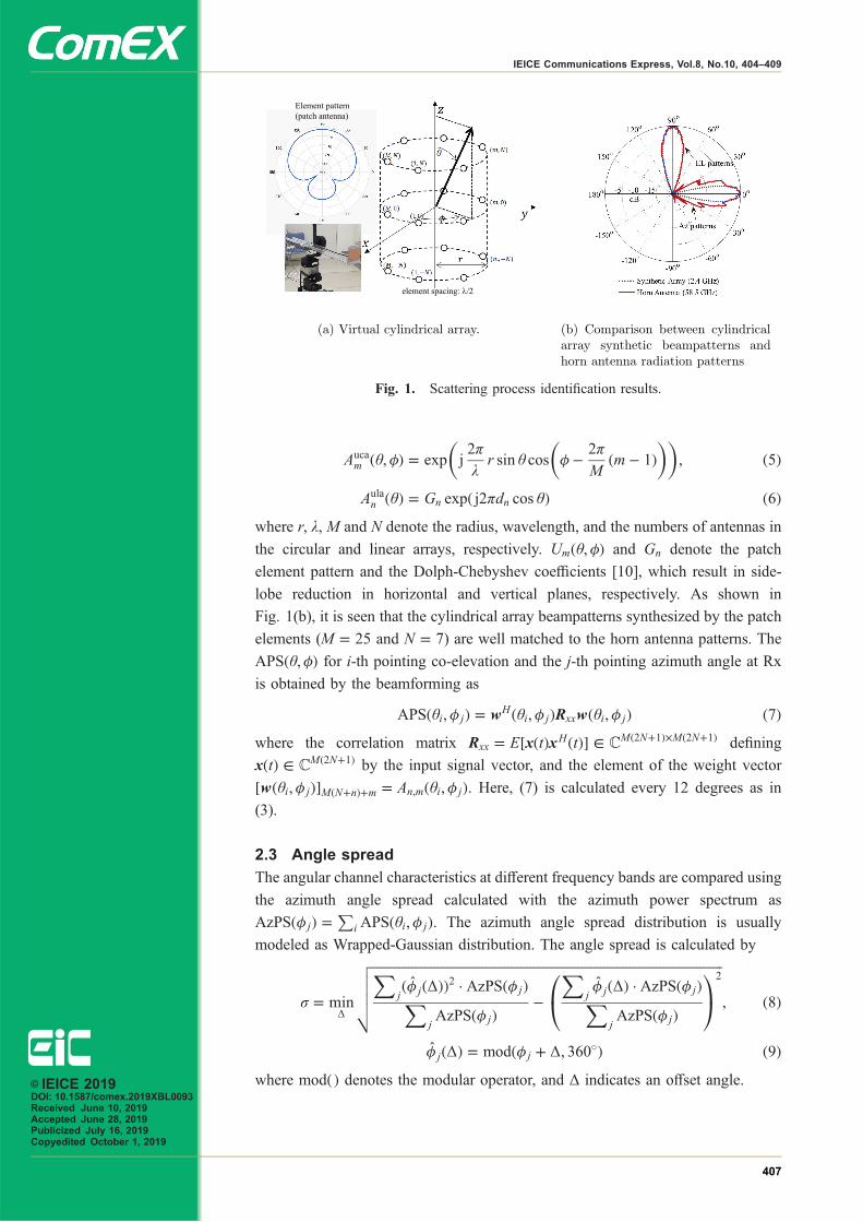
Fig. 1(a), the cylindrical antenna array structure having half-wavelength element
spacing is shown where the APS was synthesized by beamforming with the patch
antenna element of 7.3 dBi gain. The response function at the position ðm; nÞ form ¼ 1; � � � ; M, and n ¼ �N; � � � ; N can be expressed as
An;mð�; �Þ ¼ Aucan;mð�; �ÞAula
n ð�ÞUmð�; �Þ ð4Þwhere Auca
m and Aulam denote the circular and linear array responses, respectively,
which are expressed as© IEICE 2019DOI: 10.1587/comex.2019XBL0093Received June 10, 2019Accepted June 28, 2019Publicized July 16, 2019Copyedited October 1, 2019
406
IEICE Communications Express, Vol.8, No.10, 404–409
Aucam ð�; �Þ ¼ exp j
2�
�r sin � cos � � 2�
Mðm � 1Þ
� �� �; ð5Þ
Aulan ð�Þ ¼ Gn expð j2�dn cos �Þ ð6Þ
where r, λ, M and N denote the radius, wavelength, and the numbers of antennas in
the circular and linear arrays, respectively. Umð�; �Þ and Gn denote the patch
element pattern and the Dolph-Chebyshev coefficients [10], which result in side-
lobe reduction in horizontal and vertical planes, respectively. As shown in
Fig. 1(b), it is seen that the cylindrical array beampatterns synthesized by the patch
elements (M ¼ 25 and N ¼ 7) are well matched to the horn antenna patterns. The
APSð�; �Þ for i-th pointing co-elevation and the j-th pointing azimuth angle at Rx
is obtained by the beamforming as
APSð�i; �jÞ ¼ wHð�i; �jÞRxxwð�i; �jÞ ð7Þwhere the correlation matrix Rxx ¼ E½xðtÞxHðtÞ� 2 C
Mð2Nþ1Þ�Mð2Nþ1Þ defining
xðtÞ 2 CMð2Nþ1Þ by the input signal vector, and the element of the weight vector
½wð�i; �jÞ�MðNþnÞþm ¼ An;mð�i; �jÞ. Here, (7) is calculated every 12 degrees as in
(3).
2.3 Angle spread
The angular channel characteristics at different frequency bands are compared using
the azimuth angle spread calculated with the azimuth power spectrum as
AzPSð�jÞ ¼P
iAPSð�i; �jÞ. The azimuth angle spread distribution is usually
modeled as Wrapped-Gaussian distribution. The angle spread is calculated by
� ¼ min�
ffiffiffiffiffiffiffiffiffiffiffiffiffiffiffiffiffiffiffiffiffiffiffiffiffiffiffiffiffiffiffiffiffiffiffiffiffiffiffiffiffiffiffiffiffiffiffiffiffiffiffiffiffiffiffiffiffiffiffiffiffiffiffiffiffiffiffiffiffiffiffiffiffiffiffiffiffiffiffiffiffiffiffiffiffiffiffiffiffiffiffiffiffiffiffiffiffiffiffiffiffiffiffiffiffiffiXjð�̂jð�ÞÞ2 � AzPSð�jÞX
jAzPSð�jÞ
�X
j�̂jð�Þ � AzPSð�jÞX
jAzPSð�jÞ
0@
1A
2vuuut ; ð8Þ
�̂jð�Þ ¼ modð�j þ �; 360�Þ ð9Þwhere modðÞ denotes the modular operator, and Δ indicates an offset angle.
(a) Virtual cylindrical array. (b) Comparison between cylindricalarray synthetic beampatterns andhorn antenna radiation patterns
Fig. 1. Scattering process identification results.
© IEICE 2019DOI: 10.1587/comex.2019XBL0093Received June 10, 2019Accepted June 28, 2019Publicized July 16, 2019Copyedited October 1, 2019
407
IEICE Communications Express, Vol.8, No.10, 404–409
3 Measurement results
3.1 Measurement scenarios
We conducted the measurement campaign at a conference room environment which
is a typical usage scenario in IEEE 802.11ad and 802.11ay. The Tx as an access
point (AP) was set on the television at a height of approximately 2.1m close to the
wall where the antenna radiation pattern covers the front side of the wall. The
channel responses were measured at the five Rx positions (denoted by Rx1–Rx5)
where the Rx was assumed to be a station (STA), e.g., a laptop PC. The STA
antenna was located from 3.12 to 5.65m away from the AP at the height of 0.9m
from the floor (15 cm from the table). As can be seen, the LoS between Tx and Rx
was available in all Rx positions. This refers to the setup of the STA-AP conference
room sub-scenario in [1].
3.2 Results and observation
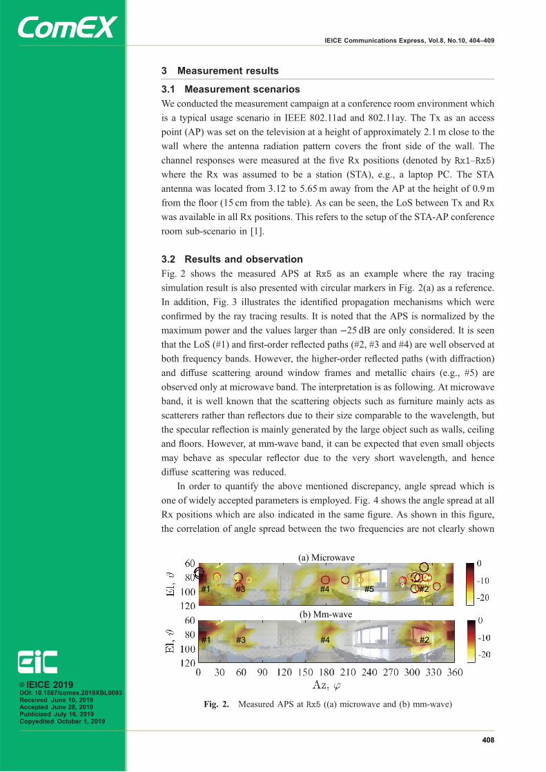
Fig. 2 shows the measured APS at Rx5 as an example where the ray tracing
simulation result is also presented with circular markers in Fig. 2(a) as a reference.
In addition, Fig. 3 illustrates the identified propagation mechanisms which were
confirmed by the ray tracing results. It is noted that the APS is normalized by the
maximum power and the values larger than −25 dB are only considered. It is seen
that the LoS (#1) and first-order reflected paths (#2, #3 and #4) are well observed at
both frequency bands. However, the higher-order reflected paths (with diffraction)
and diffuse scattering around window frames and metallic chairs (e.g., #5) are
observed only at microwave band. The interpretation is as following. At microwave
band, it is well known that the scattering objects such as furniture mainly acts as
scatterers rather than reflectors due to their size comparable to the wavelength, but
the specular reflection is mainly generated by the large object such as walls, ceiling
and floors. However, at mm-wave band, it can be expected that even small objects
may behave as specular reflector due to the very short wavelength, and hence
diffuse scattering was reduced.
In order to quantify the above mentioned discrepancy, angle spread which is
one of widely accepted parameters is employed. Fig. 4 shows the angle spread at all
Rx positions which are also indicated in the same figure. As shown in this figure,
the correlation of angle spread between the two frequencies are not clearly shown
(a) Microwave
#1 #2#3 #4 #5
(b) Mm-wave
#1 #2#3 #4
Fig. 2. Measured APS at Rx5 ((a) microwave and (b) mm-wave)
© IEICE 2019DOI: 10.1587/comex.2019XBL0093Received June 10, 2019Accepted June 28, 2019Publicized July 16, 2019Copyedited October 1, 2019
408
IEICE Communications Express, Vol.8, No.10, 404–409
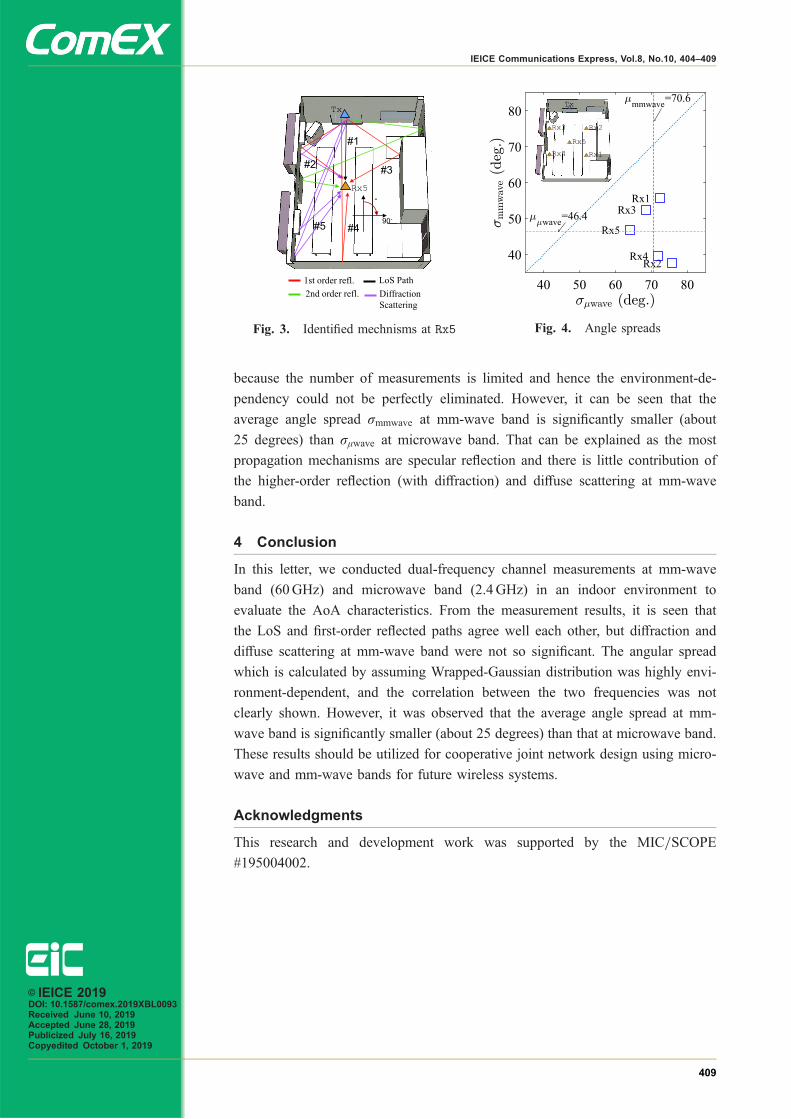
because the number of measurements is limited and hence the environment-de-
pendency could not be perfectly eliminated. However, it can be seen that the
average angle spread �mmwave at mm-wave band is significantly smaller (about
25 degrees) than ��wave at microwave band. That can be explained as the most
propagation mechanisms are specular reflection and there is little contribution of
the higher-order reflection (with diffraction) and diffuse scattering at mm-wave
band.
4 Conclusion
In this letter, we conducted dual-frequency channel measurements at mm-wave
band (60GHz) and microwave band (2.4GHz) in an indoor environment to
evaluate the AoA characteristics. From the measurement results, it is seen that
the LoS and first-order reflected paths agree well each other, but diffraction and
diffuse scattering at mm-wave band were not so significant. The angular spread
which is calculated by assuming Wrapped-Gaussian distribution was highly envi-
ronment-dependent, and the correlation between the two frequencies was not
clearly shown. However, it was observed that the average angle spread at mm-
wave band is significantly smaller (about 25 degrees) than that at microwave band.
These results should be utilized for cooperative joint network design using micro-
wave and mm-wave bands for future wireless systems.
Acknowledgments
This research and development work was supported by the MIC/SCOPE
#195004002.
Fig. 4. Angle spreadsFig. 3. Identified mechnisms at Rx5
© IEICE 2019DOI: 10.1587/comex.2019XBL0093Received June 10, 2019Accepted June 28, 2019Publicized July 16, 2019Copyedited October 1, 2019
409
IEICE Communications Express, Vol.8, No.10, 404–409