Embed Size (px)
Citation preview

1
Comparison of different joining
techniques in a crashworthiness
perspective
Massimiliano Avalle – Politecnico di Torino
Pierfranco Mauri – Henkel Loctite Italia

2
Contents
Comparison of joining techniques
Joining technique for car body construction
Mechanical testing
Results and discussion
Design of crash structures with different
joining techniques
Experimental results from crash boxes
Redesign of crash box with adhesive bonding
Comparison of the results

3
Why using alternative joining
solutions?
Adhesive bonding helps increasing stiffness
During polymerisation other fixing system is
needed
Adhesive bad compatibility with spot-welds
Adhesive and other mechanical fasteners can
join different materials
Repairing possible

4
Joints testing
Spot-weld strength
Static
Fatigue
Dynamic/Impact
Loading conditions

5
KS2 specimen
60°
30°
0°
90°
• Formerly used by Hahn
et al. for fatigue
• Material ZST340
• Samples from
for

6
Testing system
Double sliding
frame
Connections with
spherical joints
Inclined grips
(0°-90°)
piezoelectric loadpiezoelectric load--
cells cells (during
dynamic tests)
Details of the 30°
loading system

7
Testing apparatus
•• DropDrop--towertower
•• Height 12 m, Height 12 m,
•• Mass 60Mass 60--120 kg 120 kg
•• 300 kN max.300 kN max.
•• 13 m/s v13 m/s vmaxmax
•• Equipped for Equipped for
impact testing (in impact testing (in
compression)compression)
•• Equipped with Equipped with
tensile test griptensile test grip
•• Load measured Load measured
with piezoelectric with piezoelectric
loadload--cellscells
•• Stroke measured Stroke measured
with an optical with an optical
encoderencoder
•• Universal Universal
hydraulic hydraulic
material material
testing testing
equipment equipment
DARTEC DARTEC
HA100HA100
•• 100 kN max100 kN max
•• 100 mm/s v100 mm/s vmaxmax
•• Load Load
measured with measured with
a straina strain--gage gage
loadload--cellcell
•• Stroke Stroke
measured with measured with
LVDTLVDT
8
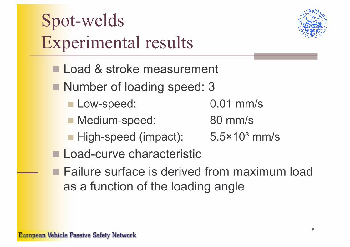
Spot-welds
Experimental results
Load & stroke measurement
Number of loading speed: 3
Low-speed: 0.01 mm/s
Medium-speed: 80 mm/s
High-speed (impact): 5.5×10³ mm/s
Load-curve characteristic
Failure surface is derived from maximum load
as a function of the loading angle

9
Spot-weld results
Low speed
0°
30°
60°
90°
• Apparatus: DARTEC HA100
• Loading speed: 0.01 mm/s
Stroke (mm)
Load (kN)

10
Spot-weld results
Medium speed
0°
30°
60°
90°
• Apparatus: DARTEC HA100
• Loading speed: 80 mm/s (=0.08 m/s)
Stroke (mm)
Load (kN)

11
Spot-weld results
High speed
0°
30°
60°
90°
• Apparatus: DARTEC HA100
• Loading speed: 5.5 m/s
Stroke (mm)
Load (kN)

12
Spot-welds
Low speed samples

13
Spot-welds
High speed samples

14
Analysis of the results
Joint strength is analysed as a function of the
loading angle:
An elliptic limit curve is assumed:
A different limit curve is obtained for each
loading speed
1
2
max
2
max
=
+
N
N
T
T

15
Spot-weld strength vs. loading
Limit curve as a function of the loading angle
( )2maxmax
2
max
tan1
1
cos NT
TF
αα +=
Loading angle (deg)
Maximum load (kN)

16
Spot-weld strength vs.
loading components
1
2
max
2
max
=
+
N
N
T
T
Maximum tensile load (kN)
Maximum shearing load (kN)
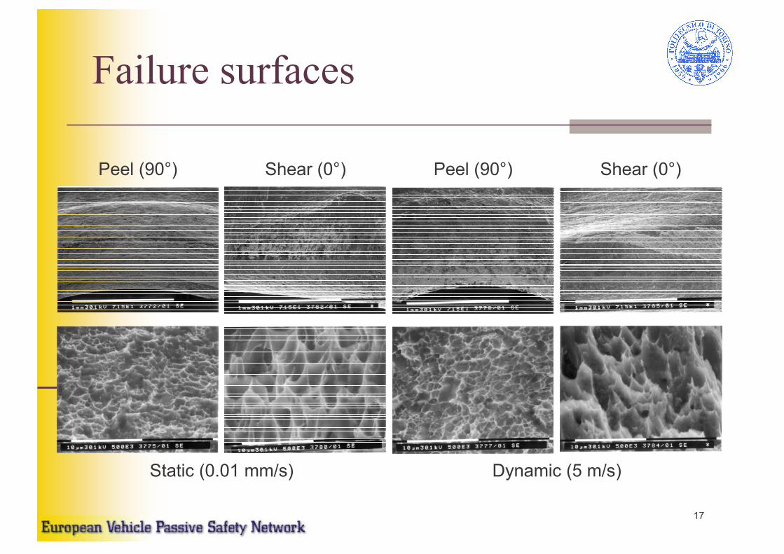
17
Failure surfaces
Static (0.01 mm/s) Dynamic (5 m/s)
Peel (90°) Shear (0°) Peel (90°) Shear (0°)

18
Alternative joining systems
for automotive constructions
Riveting
Self-riveting, punch riveting, Henrob joint
Clinching
Adhesive bonding
punch riveting Clinching

19
Clinching compared to
spot-welds (1/2)
Material: Mild Steel ( approx. 300 N/mm2)
1. Round die, ∅ 5mm 2. Round die, ∅ 8mm, 3a. Rectangular die, w. 4mm, shear 90 ° 3b.
Rectangular die, w. 4mm, shear 0 ° 4. Spot Weld, Standard spec. minimum, ∅3 & 4mm
Copyright© 2001 ATTEXOR Clinch Systems SA

20
Clinching compared to
spot-welds (2/2)
Mondino, I., Properzi, M., Giunti, T., Calderale, P.M., “La fatica di
giunzioni meccaniche per strutture veicolistiche innovative”
(Fatigue of mechanics joints for innovative car body structures)
Proceedins XXVIII AIAS Conf., 1999

21
KS2 specimen
60°30°0° 90°• Formerly used by Hahn
et al. for fatigue
• Material DC04
• Samples from

22
Clinching and Bonding
Experimental plan
KS2 specimen loaded at different angles
Clinched 21 samples
Bonded LOCTITE Hysol® 9466 21 samples
Clinched+bonded 22 samples
Loading speed: quasi-static 0.01 mm/s
Bonding procedure
Sanding (paper sand P80)
Degreasing (LOCTITE® 7063) and bonding
Polymerisation: 90 minutes @ 100°C
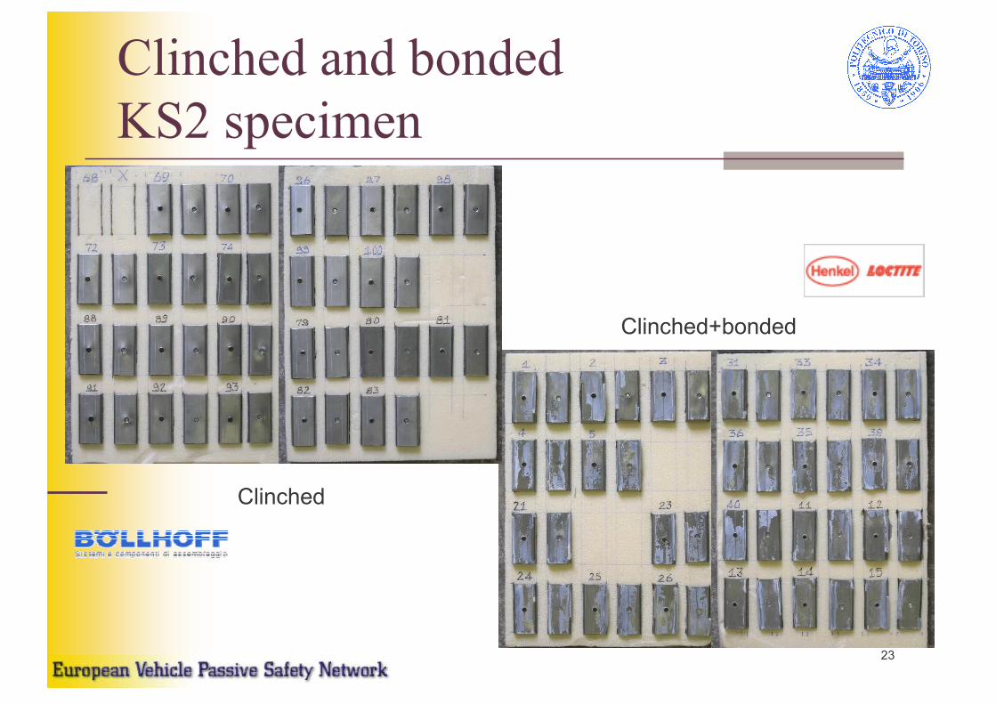
23
Clinched and bonded
KS2 specimen
Clinched+bonded
Clinched

24
Clinched & clinched+bonded
samples
Clinched+bonded,
90°Clinched+bonded,
0°
Clinched+bonded,
60°
Clinched+bonded,
30°
Clinched, 30° Clinched, 90°Clinched, 60°Clinched, 0°

25
0
0.2
0.4
0.6
0.8
1
1.2
1.4
0 0.5 1 1.5 2 2.5 3
Stroke (mm)
Load (kN)
Clinching
Test results
0°
30°
60°
90°
• Apparatus: DARTEC HA100
• Loading speed: 0.01 mm/s
26
0
2
4
6
8
10
12
0 2 4 6 8 10
Stroke (mm)
Load (kN)
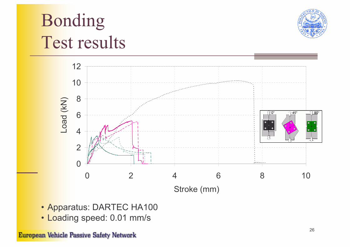
Bonding
Test results
• Apparatus: DARTEC HA100
• Loading speed: 0.01 mm/s

27
0
2
4
6
8
10
12
0 1 2 3 4 5 6
Stroke (mm)
Load (kN)
Clinching+bonding
Test results
• Apparatus: DARTEC HA100
• Loading speed: 0.01 mm/s
0°
30°
60°
90°

28
0
2
4
6
8
10
12
0 15 30 45 60 75 90
Loading angle (deg)
Maximum load (kN)
Clinched
Bonded
Clinched+bonded
Clinched and bonded joint
strength vs. loading
Limit curve vs. Loading angle
( )2maxmax
2
max
tan1
1
cos NT
TF
αα +=

29
Clinched and bonded joint
strength vs. load components
0
2
4
6
8
10
12
0 2 4 6 8 10 12
Normal load (kN)
Shear load (kN)
Clinched
Bonded
Clinched+bonded
1
2
max
2
max
=
+
N
N
T
T

30
Clinched and bonded joint
energy vs. loading angle
Failure energy vs. Loading angle
0
10
20
30
40
50
60
0 15 30 45 60 75 90
Loading angle (deg)
Failure energy (J)
Clinched
Bonded
Clinched+bonded
31
Different joining solutions:
conclusions
Joining by clinching is effective and a good
alternative to spot-weld
The use of adhesive strongly increase
strength and energy absorption capability
Clinching can be use to make bonding
operations easier: the pieces are kept in
place up to complete polymerisation
Clinching in addiction to bonding offers
additional safety as an extreme protection in
the case of adhesive premature failure

32
Behaviour of crash boxes with
alternative joining solutsions
Is it possible to substitute spot-welds with
other joining systems directly in the common
constructive solutions?
Crash behaviour can be improved?

33
• Cleaning and surface preparation with sand paper• Degreasing with Loctite 7063• Activation with Loctite 7388• Application of Loctite 330 adhesive• NDT ultrasonic inspection
Bonded crash-box production
60 60
• Cleaning and surface preparation with sand paper• Chemical degrease• Mixing of components and application of CIBA araldite adhesive• NDT ultrasonic inspection

34
NDT procedure by Rossetto & Goglio(ref. XXIX AIAS et al.)
Ultrasonic NDT inspection

35
Stress analysis of the bonded
flanges15
30
30
60 15
sp.1
F
F F
F
0
40
80
120
160
200
-10 -8 -6 -4 -2 0
coordinate y [mm]
Von Mises equivalent stress [MPa]
adhesive layer thickness 0.2 mm
adhesive layer thickness 0.4 mm
Position (mm)
Equivalent stress (MPa)

36
0
5
10
15
20
25
-10 -8 -6 -4 -2 0 2 4 6
coordinate y [mm]
Von Mises equivalent stress [MPa]
flat fillet filling
round fillet filling
Improvements by filleting
Position (mm)
Equivalent stress (MPa)

37
Quasi-static crushing
Spot-welded crash-box
0
5
10
15
20
25
30
0 10 20 30 40 50 60 70 80 90 100
spostamento [mm]
Forza [kN]
saldatura a punti - trave N4016003
saldatura a punti - trave N4016002
saldatura a punti - trave N4016001
0
200
400
600
800
1000
1200
0 10 20 30 40 50 60 70 80 90 100
spostamento [mm]
Energia [J]
saldatura a punti - trave N4016003
saldatura a punti - trave N4016002
saldatura a punti - trave N4016001
Spot-welded - test N4016003
Spot-welded - test N4016002
Spot-welded - test N4016001
Energia(J)
Stroke (mm)
Load (kN)
Stroke (mm)
Spot-welded - test N4016003
Spot-welded - test N4016002
Spot-welded - test N4016001

38
0
5
10
15
20
25
30
35
40
45
0 10 20 30 40 50 60 70 80 90 100
spostamento [mm]
Forza [kN]
adesivo LOCTITE 330 - trave B1
adesivo LOCTITE 330 - trave B5
adesivo LOCTITE 330 - trave B3
0
200
400
600
800
1000
1200
0 10 20 30 40 50 60 70 80 90 100
spostamento [mm]
Energia [J]
adesivo LOCTITE 330 - trave B1
adesivo LOCTITE 330 - trave B5
adesivo LOCTITE 330 - trave B3
Quasi-static crushing
Adhesively bonded crash-box
Bonded LOCTITE 330 - test B1
Bonded LOCTITE 330 - test B5
Bonded LOCTITE 330 - test B3
Energia(J)
Stroke (mm)
Load (kN)
Stroke (mm)
Bonded LOCTITE 330 - test B1
Bonded LOCTITE 330 - test B5
Bonded LOCTITE 330 - test B3

39
Quasi-static crushing
Comparisons (1/2)
0
200
400
600
800
1000
1200
0 10 20 30 40 50 60 70 80 90 100
spostamento [mm]
Energia [J]
saldatura a punti - trave N4016002
adesivo LOCTITE 330 - trave B1
adesivo CIBA araldite 2010 - trave B4
Stroke (mm)
Energy (J)
0
5
10
15
20
25
30
0 10 20 30 40 50 60 70 80 90 100
spostamento [mm]
Forza [kN]
saldatura a punti - trave N4016002
adesivo LOCTITE 330 - trave B1
adesivo CIBA araldite 2010 - trave B4
Stroke (mm)
Load (kN)
Spot-welded - test N4016002
Bonded - LOCTITE 330 – test B1
Bonded - CIBA Araldite 2010 - test B4
Spot-welded - test N4016002
Bonded - LOCTITE 330 – test B1
Bonded - CIBA Araldite 2010 - test B4
0
5
10
15
20
25
30
0 10 20 30 40 50 60 70 80 90 100
displacement [mm]
Force [kN]
spot weld - piece N4016003
spot weld - piece N4016002
spot weld - piece N4016001
adhesive LOCTITE 330 - piece B1
adhesive LOCTITE 330 - piece B5
adhesive LOCTITE 330 - piece B3
0
200
400
600
800
1000
1200
0 10 20 30 40 50 60 70 80 90 100
displacement [mm]
Energy [J]
spot weld - piece N4016003
spot weld - piece N4016002
spot weld - piece N4016001
adhesive LOCTITE 330 - piece B1
adhesive LOCTITE 330 - piece B3
adhesive LOCTITE 330 - piece B5
Stroke (mm)
Energy (J)
Stroke (mm)
Load (kN)

40
Mean load (kN) Max load (kN)
B1 11.62 28.57
B3 10.80 27.62
B5 11.79 41.75
mean value 11.40 32.65
stand. dev. 0.53 7.90
LOCTITE 330 adhesiveLOCTITE 330LOCTITE 330 adhesiveadhesive
Spot-weldSpotSpot--weldweldMean load (kN) Max load (kN)
N1 8.09 20.92
N2 7.92 21.92
N3 7.57 21.41
mean value 7.86 21.42
stand. dev. 0.26 0.50
Quasi-static crushing
Comparisons (2/2)

41
•Made with an ΩΩΩΩ elements bonded to a flat plate (top-
hat section)
15
60
60 15
sp.1
Alternative solutions for
improved bonded box (1/2)
15
70
60 15
sp.110
• New shape with two ΩΩΩΩelements one (smaller)
inserted into the other
AA BB

42
• Bonding flanges as simple
substitution of spot-welds
•Made with two ΩΩΩΩ elements (double hat section)
15
30
30
60 15
sp.1
60
22
22
sp. 1
16
• Double U section
• Can be obtained by joining
two identical U elements
Single-lapjoint
Alternative solutions for
improved bonded box (2/2)
CC DD

43
Components characteristics
Crash-boxes length 300 mm
Sheet thickness 0.8 mm
Material DC04 (ex FeP04)
LOCTITE 330 adhesive
procedure:
cleaning and sanding (sand-paper P100)
Application of “cleaner” 7063 and activator
7388
Polymerisation for at least 3 days

44
Quasi-static tests
Load and energy curves
C shape: 2 folds followed by global instability and debonding
other sections: regular folding some debonding (except D shape)
0
10000
20000
30000
40000
0 50 100 150 200
Schiacciamento (mm)
Carico (N)
0
750
1500
2250
3000
Energia (J)
Vel. 15 mm/min
A
0
10000
20000
30000
40000
0 50 100 150 200
Schiacciamento (mm)
Carico (N)
0
750
1500
2250
3000
Energia (J)
Vel. 15 mm/min
B
0
10000
20000
30000
40000
0 50 100 150 200
Schiacciamento (mm)
Carico (N)
0
750
1500
2250
3000
Energia (J)
Vel. 15 mm/min
C
0
10000
20000
30000
40000
0 50 100 150 200
Schiacciamento (mm)
Carico (N)
0
750
1500
2250
3000
Energia (J)
Vel. 15 mm/min
D
Energy (J)
Stroke (mm)
Load (N)
Energy (J)
Stroke (mm)
Load (N)
Energy (J)
Stroke (mm)
Load (N)
Energy (J)
Stroke (mm)
Load (N)

45
Quasi-static tests
C shape: 2 folds followed by global instability and
debonding
other sections: regular folding some debonding
(except D shape)

46
Medium-speed tests
Load and energy curves
0
10000
20000
30000
40000
0 50 100 150 200
Schiacciamento (mm)
Carico (N)
0
750
1500
2250
3000
Energia (J)
Vel. 480 mm/min
0
10000
20000
30000
40000
0 50 100 150 200
Schiacciamento (mm)
Carico (N)
0
750
1500
2250
3000
Energia (J)
Vel. 480 mm/min
0
10000
20000
30000
40000
0 50 100 150 200
Schiacciamento (mm)
Carico (N)
0
750
1500
2250
3000
Energia (J)
Vel. 480 mm/min
0
10000
20000
30000
40000
0 50 100 150 200
Schiacciamento (mm)
Carico (N)
0
750
1500
2250
3000
Energia (J)
Vel. 480 mm/min
A B
C D
C shape: 2 folds followed by global instability and debonding
other sections: regular folding some debonding (except D shape)
Energy (J)
Stroke (mm)
Load (N)
Energy (J)
Stroke (mm)
Load (N)
Energy (J)
Stroke (mm)
Load (N)
Energy (J)
Stroke (mm)
Load (N)

47
Medium-speed tests
C shape: 2 folds followed by global instability and
debonding
other sections: regular folding some debonding
(except D shape)

48
0
10000
20000
30000
40000
50000
60000
0 50 100 150 200
Schiacciamento (mm)
Carico (N)
0
200
400
600
800
1000
1200
Energia (J)
Vel. 6.5 m/s
C
Impact tests (6 m/s)
Load and energy curves
0
10000
20000
30000
40000
50000
60000
0 50 100 150 200
Schiacciamento (mm)
Carico (N)
0
200
400
600
800
1000
1200
Energia (J)
Vel. 6.5 m/s
0
10000
20000
30000
40000
50000
60000
0 50 100 150 200
Schiacciamento (mm)
Carico (N)
0
200
400
600
800
1000
1200
Energia (J)
Vel. 6.5 m/s
0
10000
20000
30000
40000
50000
60000
0 50 100 150 200
Schiacciamento (mm)
Carico (N)
0
200
400
600
800
1000
1200
Energia (J)
Vel. 6.5 m/s
A B
D
A, B, C shapes: irregular debonding in the crushed part
D shape: no debonding
Energy (J)
Stroke (mm)
Load (N)
Energy (J)
Stroke (mm)
Load (N)
Energy (J)
Stroke (mm)
Load (N)
Energy (J)
Stroke (mm)
Load (N)

49
Impact tests (6 m/s)
A, B, C shapes: irregular debonding in the crushed part
D shape: no debonding

50
Impact tests (9 m/s)
Load and energy curves
0
10000
20000
30000
40000
50000
60000
0 50 100 150 200
Schiacciamento (mm)
Carico (N)
0
400
800
1200
1600
2000
2400
Energia (J)
Vel. 9 m/s
0
10000
20000
30000
40000
50000
60000
0 50 100 150 200
Schiacciamento (mm)
Carico (N)
0
400
800
1200
1600
2000
2400
Energia (J)
Vel. 9 m/s
0
10000
20000
30000
40000
50000
60000
0 50 100 150 200
Schiacciamento (mm)
Carico (N)
0
400
800
1200
1600
2000
2400
Energia (J)
Vel. 9 m/s
picco 62.85 kN
0
10000
20000
30000
40000
50000
60000
0 50 100 150 200
Schiacciamento (mm)
Carico (N)
0
400
800
1200
1600
2000
2400
Energia (J)
Vel. 9 m/s
A B
C D
A, B, C shapes: irregular debonding in the crushed part
D shape: complete regular folding, no debonding at all
Energy (J)
Stroke (mm)
Load (N)
Energy (J)
Stroke (mm)
Load (N)
Energy (J)
Stroke (mm)
Load (N)
Energy (J)
Stroke (mm)
Load (N)

51
Impact tests (9 m/s)
A, B, C shapes: irregular debonding in the crushed part
D shape: complete regular folding, no debonding at all

52
0
10000
20000
30000
40000
50000
60000
Sez. A Sez. B Sez. C Sez. D
Carico (N) 15 mm/min
480 mm/min
6.5 m/s
9 m/s
Valore massimo
A, B shapes: maximum load in the average (≈30 kN), good energy absorption characteristics (2÷2.7 kJ)
C shape: high maximum load (35 kN), low energy absorption
(1.6-0.7 kJ), complete debonding and global instability
D shape: lowest maximum load (24-28 kN), good energy
absorption (1.6-1.8 kJ), regular folding
Quasi-static and medium-speed tests
Comparison of the different
shapes: low speedMaximum load(kN)

53
0
10000
20000
30000
40000
50000
60000
Sez. A Sez. B Sez. C Sez. D
Carico (N) 15 mm/min
480 mm/min
6.5 m/s
9 m/s
Valore massimo
C shape: high maximum load (53-63 kN), low compression (50-
104 mm);
B shape: low maximum load (39 kN) and crushing (57-115 mm);
A shape: average maximum load (38-51 kN), high crushing
(111-184 mm)
D shape: quite low maximum load (39-44 kN), high crushing
(83-181 mm), regular folding
Comparison of the different
shapes: high speedMaximum load(kN)

54
Conclusions
Similar results both from low and medium speed and
impact tests
Adhesive bonding is a good solution also for energy
absorption during crash
Sensitive improvements by means of suitable (but
simple) geometrical modification of more common
shapes used for spot-welded structures:
- C shape: bonded sections normal to sides → bad
design
- D shape: bonded sections parallel to sides →optimal design