Embed Size (px)
Citation preview
FPZ S.p.A. Via F.lli Cervi 16
20863 Concorezzo (MB), ITALIA Tel. +39 039 69 06 81
[email protected] www.fpz.com
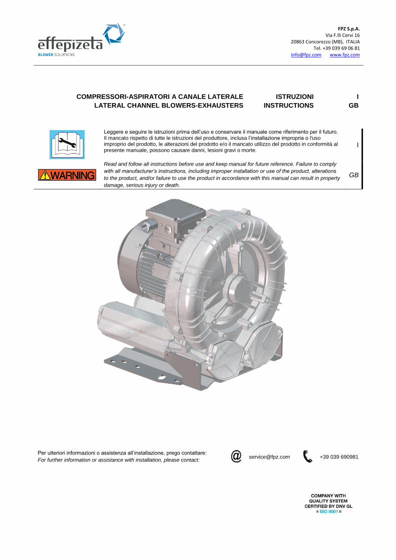
Leggere e seguire le istruzioni prima dell’uso e conservare il manuale come riferimento per il futuro. Il mancato rispetto di tutte le istruzioni del produttore, inclusa l’installazione impropria o l'uso improprio del prodotto, le alterazioni del prodotto e/o il mancato utilizzo del prodotto in conformità al presente manuale, possono causare danni, lesioni gravi o morte.
I
Read and follow all instructions before use and keep manual for future reference. Failure to comply
with all manufacturer’s instructions, including improper installation or use of the product, alterations
to the product, and/or failure to use the product in accordance with this manual can result in property
damage, serious injury or death.
GB
Per ulteriori informazioni o assistenza all’installazione, prego contattare:
+39 039 690981
For further information or assistance with installation, please contact:
COMPRESSORI-ASPIRATORI A CANALE LATERALE ISTRUZIONI I
LATERAL CHANNEL BLOWERS-EXHAUSTERS INSTRUCTIONS GB
FPZ S.p.A. Via F.lli Cervi 16
20863 Concorezzo (MB), ITALIA Tel. +39 039 69 06 81
[email protected] www.fpz.com
Table of contents 1 GENERAL INFORMATION ............................................................................................................................................................... 3
1.1 PURPOSE OF MANUAL ............................................................................................................................................................ 3
1.1 TECHNICAL DATA – NAMEPLATE ........................................................................................................................................... 3
1.1 TESTING, WARRANTY AND LIABILITY .................................................................................................................................... 3
2 SAFETY RULES ............................................................................................................................................................................... 4
2.1 IMPORTANT SAFETY INFORMATION ..................................................................................................................................... 4
2.2 PROHIBITIONS ......................................................................................................................................................................... 4
3 PROPER AND IMPROPER USE ....................................................................................................................................................... 5
3.1 OPERATING CONDITIONS....................................................................................................................................................... 5
3.2 STANDARD SIDE CHANNEL BLOWER .................................................................................................................................... 5
3.3 ATEX BLOWERS (Category 3GD – Category 2G) ..................................................................................................................... 5
3.4 IMPROPER USE AND ASSOCIATED RISKS ............................................................................................................................ 6
4 STORAGE AND TRANSPORT.......................................................................................................................................................... 7
4.1 RECEIPT AND CHECK OF THE PACKAGE .............................................................................................................................. 7
4.2 HANDLING AND TRANSPORT ................................................................................................................................................. 7
4.3 STORAGE ................................................................................................................................................................................. 7
5 INSTALLATION ................................................................................................................................................................................. 7
5.1 INSTALLATION CONDITIONS .................................................................................................................................................. 7
5.2 BLOWER WITHOUT ELECTRIC MOTOR (GOR – GVR EXECUTION) ..................................................................................... 9
5.3 ATEX 2G BLOWER (EXCLUDED TMD VERSION) ................................................................................................................... 9
5.4 GOR TMD ATEX 2G BLOWER .................................................................................................................................................. 9
5.4.1 INSTALLATION OF SENSOR GOR TMD ATEX 2G BLOWERS .................................................................................... 10
5.4.2 CONNECTION OF THE MECHANICAL SEAL FOR GOR TMD ATEX 2G BLOWER ..................................................... 11
5.5 ELECTRIC MOTOR ................................................................................................................................................................. 12
5.5.1 ELECTRIC CONNECTION ............................................................................................................................................. 12
5.5.2 ELECTRIC MOTOR POWERED BY FREQUENCY CONVERTER ................................................................................ 12
5.5.3 ROTATION DIRECTION ................................................................................................................................................ 13
6 START UP AND NORMAL OPERATION ........................................................................................................................................ 13
6.1 PRELIMINARY CHECKS ......................................................................................................................................................... 13
6.2 OPERATION............................................................................................................................................................................ 13
6.3 STOPPING .............................................................................................................................................................................. 14
7 MAINTENANCE .............................................................................................................................................................................. 15
7.1 MAINTENANCE AND FAILURE CONDITIONS........................................................................................................................ 15
7.2 PERIODICAL CHECKS ........................................................................................................................................................... 16
7.3 ROUTINE MAINTENANCE REPAIR OF BREAKDOWNS ........................................................................................................ 16
7.4 LIFESPAN OF BEARINGS ...................................................................................................................................................... 16
7.5 DISMANTLING AND DEMOLITION ......................................................................................................................................... 16
8 RESIDUAL RISKS ........................................................................................................................................................................... 17
9 TROUBLESHOOTING .................................................................................................................................................................... 18
10 REFERENCES ........................................................................................................................................................................ 19
11 INSTALLATION DIAGRAMS .................................................................................................................................................... 20
FPZ S.p.A. Via F.lli Cervi 16
20863 Concorezzo (MB), ITALIA Tel. +39 039 69 06 81
[email protected] www.fpz.com
Pag. 3 a 18
1 GENERAL INFORMATION
Read the manual for safety information on correct installation, operation and maintenance.
1.1 PURPOSE OF MANUAL
• The purpose of the manual is to complete the information contained in the operative instructions (Figure 1) supplied with the blower
in order to give "instructions for use" to the skilled operator to prevent and minimize risks during the interaction between man and
machine.
• For safe installation, carefully read this manual before installing the product and follow all instructions exactly as shown.
• The information was prepared by the manufacturer in the original language (ITALIAN) considering the content communication
effectiveness for the interested parties also depending on the operator’s qualifications and perspicacity.
• Keep the operative instructions (Figure 1) for the entire service life of the unit in a known and easy to access place to make it
always at hand for reference.
• Any observations made by recipients can be an important contribution to improve the after-sales services provided by the
manufacturer.
• The information contained in this manual is intended for use by specialized operators whose definition is contained in the document
MAN_PIC (Figure 2).
Figure 1 – Operating Instruction
Figure 2 - Document MAN_PIC
1.1 TECHNICAL DATA – NAMEPLATE
On the product nameplate are stated:
• Unit description
• Performance (Noise [dB], Flow [m3/h] and Pressure [mbar]) at 50 Hz and 60 Hz frequency referring to 20°C and 1013 mbar abs.
• Serial number and year of manufacture
• Reference Doc. (Operating Instruction)
• Weight [kg/lbs]
• Reference temperature for the working blower (T. amb)
1.1 TESTING, WARRANTY AND LIABILITY
Testing and inspection
• The entire unit is sent to the customer ready for installation, after passing the tests and inspections required by the manufacturer, in conformity with the applicable laws and the mandatory technical standards.
Warranty
• Warranties are defined in the general terms and conditions of sale. Liability
• See document MAN_PIC.
It is strictly forbidden to remove or tamper with the product label.
Pag. 4 of 20
2 SAFETY RULES
2.1 IMPORTANT SAFETY INFORMATION
• Do not start the unit until its operation is clearly understood.
• All installation, commissioning and maintenance operations must be carried out by specialized operators only (see doc MAN_PIC).
• Keep the area around the unit constantly free of obstructions.
• Use appropriate PPE (Personal Protective Equipment) such as boots, gloves, goggles and work clothes.
• Pay attention to all danger and caution signs placed on the unit.
• Do not wear clothes, jewelry or accessories that can get caught in the cooling fan of the electric motor or that can be sucked into
the blower.
• Do not modify the electrical connections on the unit.
• Observe all local, state and national electrical codes.
• Before starting the unit and/or with weekly frequency, the operator must check the efficiency of the devices that ensure the
operation of the unit and any other unit defects. In case of any defects, immediately notify FPZ S.p.A.
• Devices that ensure the operation of the unit must never be removed or rendered useless.
• During maintenance or repair work, it may be necessary to exclude some mentioned devices from the service. This operation must
be carried out by specialized operators only (see doc MAN_PIC).
• Always apply and enforce the safety rules; in case of any doubts, always consult this manual before acting.
2.2 PROHIBITIONS
Failure to comply the following PROHIBITIONS can cause personal (even serious) injury (or death) or
damage to equipment.
• NEVER suck up and convey aggressive, corrosive, and/or harmful fluids.
• NEVER use the unit under conditions that differ from those indicated on the nameplate.
• NEVER use the unit without having installed a suction filter.
• NEVER operate with the suction and/or delivery openings closed.
• NEVER make conversions or changes to the unit, maintenance or repair work on one’s own initiative or not envisaged in the manual. Maintenance work can be carried out only in compliance with what is described in this user manual, exclusively by specialized operators (see document MAN_PIC).
• NEVER use the unit in places where ATEX classification does not comply with Annex II of Directive 1999/92/EC.
• NEVER use the unit without having first installed and connected the sensors and/or regulators required to the plant and correctly installed and checked the seal system of the machine.
• NEVER use the unit with ambient temperatures below -15°C (+5°F) and above +40°C (+104°F).
• NEVER use the unit before ensuring correspondence between grid voltage and motor label voltage.
The instructions listed below must be read carefully and become a fundamental part of daily procedures
in the normal use and maintenance of all the equipment, in order to prevent any kind of personal or
domestic animals (even serious) injury (or death) or damage to equipment.
Non-compliant installation with the unit's intended use can cause personal (even serious) injury (or
death) or damage to equipment.
The unit must only be started:
• in conformity with the purposes of use, transport and handling specified in "FORESEEN USE";
• respecting the values given in the nameplate data.
Pag. 5 of 20
3 PROPER AND IMPROPER USE
3.1 OPERATING CONDITIONS
3.2 STANDARD SIDE CHANNEL BLOWER
FPZ side channel blowers / exhausters are designed to generate vacuum and overpressure for conveying non-explosive, non-flammable, non-dangerous gases and air in continuous use in a non-explosive environment. Side channel blowers are not designed to transport dusts of any grain size.
FPZ side channel blowers / exhausters are designed and built for use in industrial plants and are equipped with three-phase or single-
phase asynchronous bipolar electric motors in compliance with IEC 60034-1.
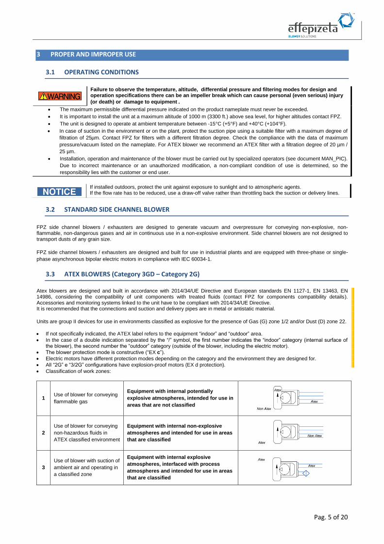
3.3 ATEX BLOWERS (Category 3GD – Category 2G)
Atex blowers are designed and built in accordance with 2014/34/UE Directive and European standards EN 1127-1, EN 13463, EN 14986, considering the compatibility of unit components with treated fluids (contact FPZ for components compatibility details). Accessories and monitoring systems linked to the unit have to be compliant with 2014/34/UE Directive. It is recommended that the connections and suction and delivery pipes are in metal or antistatic material.
Units are group II devices for use in environments classified as explosive for the presence of Gas (G) zone 1/2 and/or Dust (D) zone 22.
• If not specifically indicated, the ATEX label refers to the equipment “indoor” and “outdoor” area.
• In the case of a double indication separated by the “/” symbol, the first number indicates the “indoor” category (internal surface of the blower), the second number the “outdoor” category (outside of the blower, including the electric motor).
• The blower protection mode is constructive (“EX c”).
• Electric motors have different protection modes depending on the category and the environment they are designed for.
• All “2G” e “3/2G” configurations have explosion-proof motors (EX d protection).
• Classification of work zones:
1 Use of blower for conveying
flammable gas
Equipment with internal potentially
explosive atmospheres, intended for use in
areas that are not classified
2
Use of blower for conveying
non-hazardous fluids in
ATEX classified environment
Equipment with internal non-explosive
atmospheres and intended for use in areas
that are classified
3
Use of blower with suction of
ambient air and operating in
a classified zone
Equipment with internal explosive
atmospheres, interfaced with process
atmospheres and intended for use in areas
that are classified
Failure to observe the temperature, altitude, differential pressure and filtering modes for design and operation specifications there can be an impeller break which can cause personal (even serious) injury
(or death) or damage to equipment.
• The maximum permissible differential pressure indicated on the product nameplate must never be exceeded.
• It is important to install the unit at a maximum altitude of 1000 m (3300 ft.) above sea level, for higher altitudes contact FPZ.
• The unit is designed to operate at ambient temperature between -15°C (+5°F) and +40°C (+104°F).
• In case of suction in the environment or on the plant, protect the suction pipe using a suitable filter with a maximum degree of
filtration of 25µm. Contact FPZ for filters with a different filtration degree. Check the compliance with the data of maximum
pressure/vacuum listed on the nameplate. For ATEX blower we recommend an ATEX filter with a filtration degree of 20 µm /
25 µm.
• Installation, operation and maintenance of the blower must be carried out by specialized operators (see document MAN_PIC).
Due to incorrect maintenance or an unauthorized modification, a non-compliant condition of use is determined, so the
responsibility lies with the customer or end user.
If installed outdoors, protect the unit against exposure to sunlight and to atmospheric agents. If the flow rate has to be reduced, use a draw-off valve rather than throttling back the suction or delivery lines.
Pag. 6 of 20
3.4 IMPROPER USE AND ASSOCIATED RISKS
• Listed below are some improper uses, identified through risk assessment and experiences. Improper uses are subdivided
according to the conditions that they may generate.
• The list is a non-exhaustive and representative example of improper use and associated risks.
IMPROPER USE POSSIBLE CONSEQUENCES RISKS
IMPROPER USE LINKED TO NORMAL OPERATION
Absence of cyclic monitoring and control.
Anomalous operation not detected / hidden.
Risk of damage to the unit, with possible injury (or death) for the operator if present nearby.
Different installation with respect to manufacturer’s suggestion.
Yielding / break of fastening points. Risk of damage to the unit, with possible injury (or death) for the operator if present nearby. The unit may fall or be subject to damage due to incorrect load at support.
Operation outside the performance indicated on the blower and electric nameplate.
Seizure of the impeller. Risk of damage to the unit, with possible injury (or death) for the operator if present nearby. The unit may break.
Proceeding at all stages without consulting the operating instructions and this manual.
Using the unit for unforeseen purposes and without considering the associated risk factors.
Risk of damage to the unit, with possible injury (or death) for the operator if present nearby.
IMPROPER USE LINKED TO METHODS OF USE
Use of a fluid different from that indicated / forbidden.
Incorrect workload. Risk of damage to the unit, with possible injury (or death) for the operator if present nearby. The unit may break.
Physical load applied to the machine (no element excluded).
Breakage and/or presence of leakage of fluid collected.
Risk of damage to the unit, with possible injury (or death) for the operator if present nearby due to inhalation of harmful substances.
IMPROPER USE LINKED TO THE STOPPAGE OF A BLOWER
Manipulation of the machine still rotating / moving.
Direct contact of the operator with moving parts and with the surface unit still hot.
Risk of possible injury for the operator such as burns and entanglement.
Disconnecting the unit from the electricity with the voltage inserted.
Direct contact of the operator with the live parts.
Risk of possible injuries for the operator through electrocution.
IMPROPER USE LINKED TO MAINTENANCE WORK
Handling the machine differently from instructions for use.
Falling or sudden movement of the unit.
Risk of damage to the unit, with possible injury for the operator if present nearby.
Use of liquid during unit cleaning operations.
In case of stagnation, characteristics of the material may be compromised.
Risk of damage to the unit, with possible injury for the operator if present nearby.
Use of types of spare parts different to those supplied by FPZ.
Different performance from design (pressure, noise, vibration, sealing).
Risk of damage to the unit, with possible injury for the operator if present nearby.
BREAKDOWN AND EMERGENCY CONDITIONS
Not stopping the machine when it is making an unusual noise.
Seizure of the impeller and overheating of the unit and of the electric motor.
Risk of damage for the unit, with possible injury (or death) for the operator if present nearby. The unit may break down.
Non-compliance with the unit’s intended use or with prohibitions/obligations can cause personal (also
serious) injury (or death) or equipment damage.
Pag. 7 of 20
4 STORAGE AND TRANSPORT
4.1 RECEIPT AND CHECK OF THE PACKAGE
• When receiving the unit, it is necessary to check that the packaging is intact and free from signs of damage due to transport or storage conditions.
• In the case of damage to the packaging, immediately inform the shipping agent and the manufacturer.
4.2 HANDLING AND TRANSPORT
4.3 STORAGE
• Store in a dry place, possibly keeping the machine in the packaging.
• Do not remove the protective covers of the openings.
• In the event of long-term storage, remove dust deposits on external surfaces and, before commissioning, check the unit's functional status with a startup test.
5 INSTALLATION
5.1 INSTALLATION CONDITIONS
Danger of crushing and / or impacting various parts of the body
During the transport and handling phases due to the sudden drop or displacement of the packaging, there may be a risk of crushing and
/ or impacting various parts of the body. During the activities around the unit, the operator may fall due to stumbling or slipping.
Use equipment compliant with the laws and follow the handling and manual handling procedures described in the operating manual, based on the weight indications on the packaging and in accordance with applicable regulations in the state in which this activity takes place. Use safety shoes during this phase.
Commissioning and operation must only take place under the following installation conditions:
• The unit must be completely assembled and intact (not damaged or tampered).
• Silencers must be connected to the pipe system (see operating instructions); if silencers are not present, make sure that the connection is made by flexible sleeve.
• The machine must be securely fastened to the predetermined site and in the recommended modes (see operating instructions).
• The motor must be connected to a suitable control panel.
• Ensure the visibility of the unit installed from the position of the control elements.
Danger of ejection of objects
The entry of foreign bodies into the unit, even if very small, can cause personal serious injury (or death) and/or equipment damage with probable breakage of the impeller blades, including the danger of debris can be thrown out of the machine violently. Remove the closure caps from the silencers and connect the pipes of the system, making sure to carry out the operation in a non-dusty area to prevent the entry of foreign bodies.
Danger of crushing and / or impacting various parts of the body
During the installation phase due to the sudden drop or displacement of the packaging, there may be a risk of crushing and / or impacting various parts of the body. During work around the unit, the operator may fall due to stumbling or slipping. Use the appropriate device (eg. toe) to hook and lift the unit properly.
Danger of injury to upper limbs
The risk of injury to upper limbs may arise due to a combination of hazards during the mechanical assembly phase and the connection of the machine to the piping. Observe the operating manual to install the unit safely.
Pag. 8 of 20
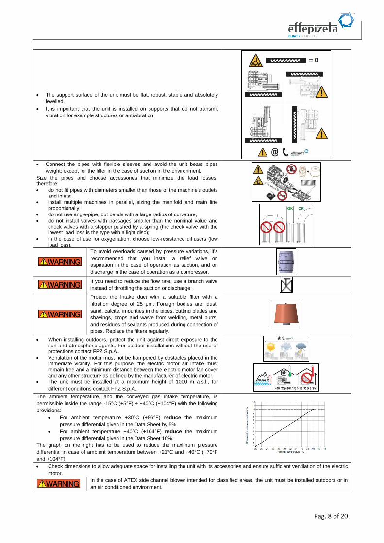
• The support surface of the unit must be flat, robust, stable and absolutely
levelled.
• It is important that the unit is installed on supports that do not transmit
vibration for example structures or antivibration
• Connect the pipes with flexible sleeves and avoid the unit bears pipes
weight; except for the filter in the case of suction in the environment.
Size the pipes and choose accessories that minimize the load losses, therefore:
• do not fit pipes with diameters smaller than those of the machine's outlets and inlets;
• install multiple machines in parallel, sizing the manifold and main line proportionally;
• do not use angle-pipe, but bends with a large radius of curvature;
• do not install valves with passages smaller than the nominal value and check valves with a stopper pushed by a spring (the check valve with the lowest load loss is the type with a light disc);
• in the case of use for oxygenation, choose low-resistance diffusers (low load loss).
To avoid overloads caused by pressure variations, it’s
recommended that you install a relief valve on
aspiration in the case of operation as suction, and on
discharge in the case of operation as a compressor.
If you need to reduce the flow rate, use a branch valve
instead of throttling the suction or discharge.
Protect the intake duct with a suitable filter with a
filtration degree of 25 μm. Foreign bodies are: dust,
sand, calcite, impurities in the pipes, cutting blades and
shavings, drops and waste from welding, metal burrs,
and residues of sealants produced during connection of
pipes. Replace the filters regularly.
• When installing outdoors, protect the unit against direct exposure to the sun and atmospheric agents. For outdoor installations without the use of protections contact FPZ S.p.A..
• Ventilation of the motor must not be hampered by obstacles placed in the immediate vicinity. For this purpose, the electric motor air intake must remain free and a minimum distance between the electric motor fan cover and any other structure as defined by the manufacturer of electric motor.
• The unit must be installed at a maximum height of 1000 m a.s.l., for
different conditions contact FPZ S.p.A..
The ambient temperature, and the conveyed gas intake temperature, is
permissible inside the range -15°C (+5°F) ÷ +40°C (+104°F) with the following
provisions:
• For ambient temperature +30°C (+86°F) reduce the maximum
pressure differential given in the Data Sheet by 5%;
• For ambient temperature +40°C (+104°F) reduce the maximum
pressure differential given in the Data Sheet 10%.
The graph on the right has to be used to reduce the maximum pressure
differential in case of ambient temperature between +21°C and +40°C (+70°F
and +104°F)
• Check dimensions to allow adequate space for installing the unit with its accessories and ensure sufficient ventilation of the electric
motor.
In the case of ATEX side channel blower intended for classified areas, the unit must be installed outdoors or in
an air conditioned environment.
Pag. 9 of 20
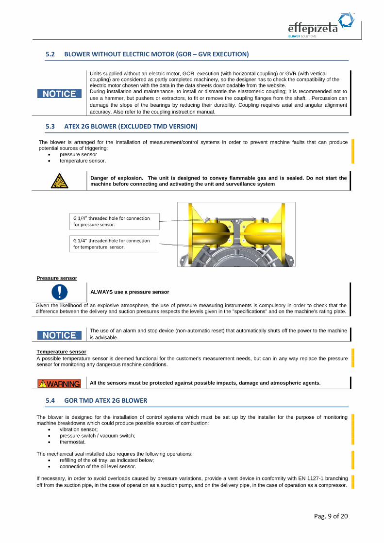
5.2 BLOWER WITHOUT ELECTRIC MOTOR (GOR – GVR EXECUTION)
5.3 ATEX 2G BLOWER (EXCLUDED TMD VERSION)
The blower is arranged for the installation of measurement/control systems in order to prevent machine faults that can produce potential sources of triggering:
• pressure sensor
• temperature sensor.
Pressure sensor
Temperature sensor
A possible temperature sensor is deemed functional for the customer's measurement needs, but can in any way replace the pressure sensor for monitoring any dangerous machine conditions.
5.4 GOR TMD ATEX 2G BLOWER
The blower is designed for the installation of control systems which must be set up by the installer for the purpose of monitoring machine breakdowns which could produce possible sources of combustion:
• vibration sensor;
• pressure switch / vacuum switch;
• thermostat. The mechanical seal installed also requires the following operations:
• refilling of the oil tray, as indicated below;
• connection of the oil level sensor. If necessary, in order to avoid overloads caused by pressure variations, provide a vent device in conformity with EN 1127-1 branching
off from the suction pipe, in the case of operation as a suction pump, and on the delivery pipe, in the case of operation as a compressor.
Units supplied without an electric motor, GOR execution (with horizontal coupling) or GVR (with vertical coupling) are considered as partly completed machinery, so the designer has to check the compatibility of the electric motor chosen with the data in the data sheets downloadable from the website. During installation and maintenance, to install or dismantle the elastomeric coupling; it is recommended not to
use a hammer, but pushers or extractors, to fit or remove the coupling flanges from the shaft. . Percussion can
damage the slope of the bearings by reducing their durability. Coupling requires axial and angular alignment
accuracy. Also refer to the coupling instruction manual.
Danger of explosion. The unit is designed to convey flammable gas and is sealed. Do not start the machine before connecting and activating the unit and surveillance system
ALWAYS use a pressure sensor
Given the likelihood of an explosive atmosphere, the use of pressure measuring instruments is compulsory in order to check that the difference between the delivery and suction pressures respects the levels given in the "specifications" and on the machine's rating plate.
The use of an alarm and stop device (non-automatic reset) that automatically shuts off the power to the machine
is advisable.
All the sensors must be protected against possible impacts, damage and atmospheric agents.
G 1/4” threaded hole for connection for pressure sensor. SENSORE Pressione
G 1/4” threaded hole for connection for temperature sensor.
Pag. 10 of 20
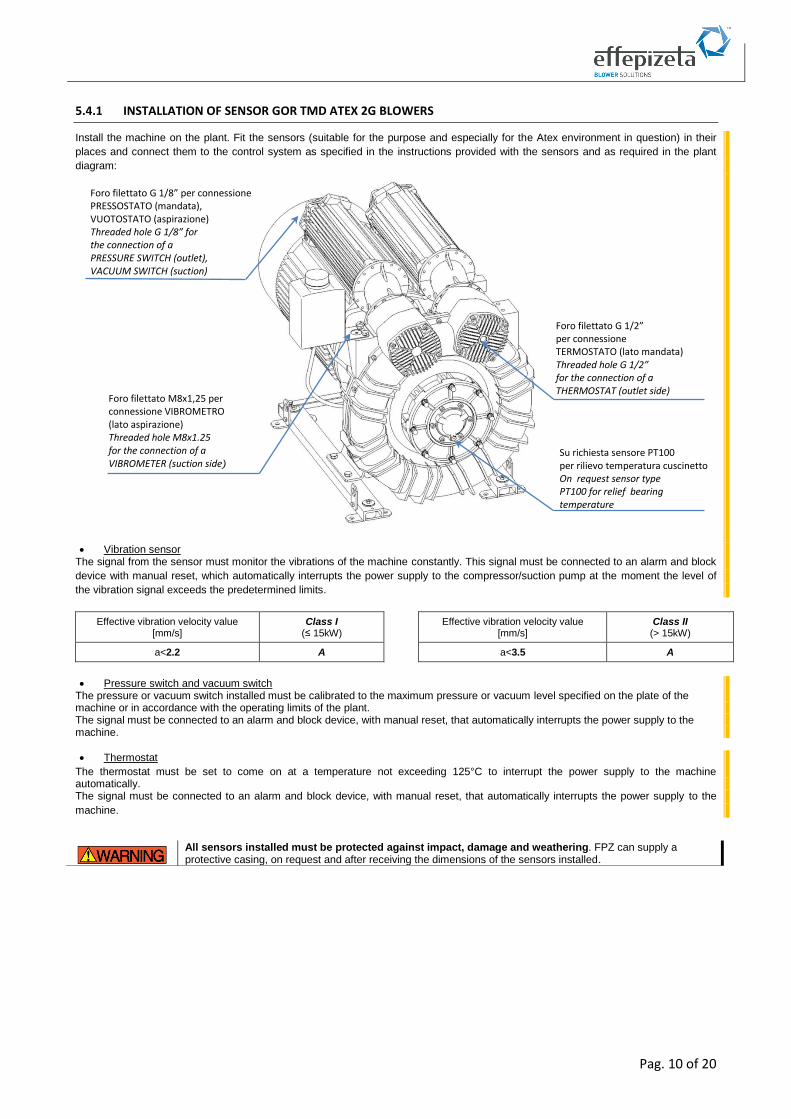
5.4.1 INSTALLATION OF SENSOR GOR TMD ATEX 2G BLOWERS
Install the machine on the plant. Fit the sensors (suitable for the purpose and especially for the Atex environment in question) in their
places and connect them to the control system as specified in the instructions provided with the sensors and as required in the plant
diagram:
• Vibration sensor The signal from the sensor must monitor the vibrations of the machine constantly. This signal must be connected to an alarm and block
device with manual reset, which automatically interrupts the power supply to the compressor/suction pump at the moment the level of
the vibration signal exceeds the predetermined limits.
Effective vibration velocity value [mm/s]
Class I (≤ 15kW)
Effective vibration velocity value [mm/s]
Class II (> 15kW)
a<2.2 A a<3.5 A
• Pressure switch and vacuum switch The pressure or vacuum switch installed must be calibrated to the maximum pressure or vacuum level specified on the plate of the machine or in accordance with the operating limits of the plant. The signal must be connected to an alarm and block device, with manual reset, that automatically interrupts the power supply to the machine.
• Thermostat
The thermostat must be set to come on at a temperature not exceeding 125°C to interrupt the power supply to the machine automatically. The signal must be connected to an alarm and block device, with manual reset, that automatically interrupts the power supply to the
machine.
All sensors installed must be protected against impact, damage and weathering. FPZ can supply a protective casing, on request and after receiving the dimensions of the sensors installed.
Foro filettato M8x1,25 per connessione VIBROMETRO (lato aspirazione) Threaded hole M8x1.25 for the connection of a VIBROMETER (suction side)
Foro filettato G 1/8” per connessione PRESSOSTATO (mandata), VUOTOSTATO (aspirazione) Threaded hole G 1/8” for the connection of a PRESSURE SWITCH (outlet), VACUUM SWITCH (suction)
Foro filettato G 1/2” per connessione TERMOSTATO (lato mandata) Threaded hole G 1/2” for the connection of a THERMOSTAT (outlet side)
Su richiesta sensore PT100 per rilievo temperatura cuscinetto On request sensor type PT100 for relief bearing temperature
Pag. 11 of 20
5.4.2 CONNECTION OF THE MECHANICAL SEAL FOR GOR TMD ATEX 2G BLOWER
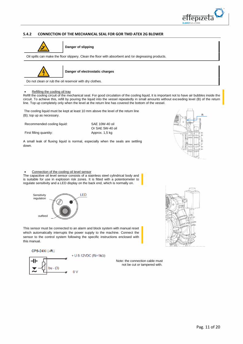
• Refilling the cooling oil tray Refill the cooling circuit of the mechanical seal. For good circulation of the cooling liquid, it is important not to have air bubbles inside the circuit. To achieve this, refill by pouring the liquid into the vessel repeatedly in small amounts without exceeding level (B) of the return line. Top up completely only when the level at the return line has covered the bottom of the vessel.
The cooling liquid must be kept at least 10 mm above the level of the return line
(B); top up as necessary.
Recommended cooling liquid: SAE 10W-40 oil
Or SAE 5W-40 oil
First filling quantity: Approx. 1,5 kg
A small leak of fluxing liquid is normal, especially when the seals are settling
down.
• Connection of the cooling oil level sensor The capacitive oil level sensor consists of a stainless steel cylindrical body and is suitable for use in explosion risk zones. It is fitted with a potentiometer to regulate sensitivity and a LED display on the back end, which is normally on.
This sensor must be connected to an alarm and block system with manual reset
which automatically interrupts the power supply to the machine. Connect the
sensor to the control system following the specific instructions enclosed with
this manual.
Danger of slipping
Oil spills can make the floor slippery. Clean the floor with absorbent and /or degreasing products.
Danger of electrostatic charges
Do not clean or rub the oil reservoir with dry clothes.
Note: the connection cable must not be cut or tampered with.
Sensitivity regulation
outfeed
B

Pag. 12 of 20
5.5 ELECTRIC MOTOR
Before starting working on the unit or system, the following precautions must be taken:
• make sure that the unit is NOT connected to electrical power mains;
• take precautions to prevent electricity from being reconnected;
• open the terminal box only after making sure that there is absolutely no live current.
5.5.1 ELECTRIC CONNECTION
Incorrect motor connection may seriously damage the unit.
• Check that the details on the data plate are compatible with the line voltage and
frequency.
• Always connect the motor’s earth cable to the relevant terminal marked with this symbol
before connecting to the mains supply and check the dispersion capacity. The earth
cable can be recognized by its color (yellow/green).
• Connect the machine to the earth system too, using the specific hole (marked with the
relative symbol) located on the base of the unit. Connection to the power grid must be
carried out in compliance with what is shown in the diagram inside the terminal box.
• Use the cable gland openings to allow power supply cables to pass into the terminal box.
• Proceed to tighten the power supply cables, taking the section of the electrical cables
into account each time.
• The terminal boards for the electrical connections must be tightened properly to avoid high contact resistances and resulting
overheating.
• Check that the insulation gaps between the various conductors are kept in the air and between surfaces, as indicated in the
standards.
• All the screws used to close the terminal board must be tightened properly. Damaged screws must be replaced immediately, using screws of the same or better quality.
The connection must guarantee:
• long-lasting safety;
• that no wire ends are sticking out;
• protection with a (thermal or amperometric) trip switch is essential for dealing with risks of overloading, a loss of one phase in the
mains supply, excessive voltage fluctuations, or the rotor getting stuck;
• that the motor trip switch have to be set using the current level shown on the nameplate as a maximum.
5.5.2 ELECTRIC MOTOR POWERED BY FREQUENCY CONVERTER
The unit’s nominal pressure or vacuum characteristics for service at mains frequency cannot be maintained if the unit is powered via a
frequency converter. Contact FPZ S.p.A. for information about unit powered by a frequency converter performance.
When power is supplied with a frequency converter, the installer is responsible for:
• respecting the laws;
• checking with FPZ assistance if the motor can be powered by a frequency converter, if it doesn’t appear on data sheet;
• checking and making any measures necessary to comply with the immunity and emission limits set by the standards;
• checking the suitability of the plant and the frequency converter for operation with standard motors (class F), or the need to use
specific motors for these types of operation.
Comply with safety measures and instructions indicated in the instruction manual for the electric motor.
Danger due to electricity
• If connecting operations are carried out without removing the voltage from the electrical system or without setting up a system to avoid reinsertion, direct contact between the operator and the live parts can occur. This can also cause personal serious injury (or death).
• Work on electrical equipment (installation and maintenance) has to be done only by specialized operators (see document MAN_PIC), wearing PPE.
• In the event of contact with a defective unit there is a risk of electrocution. Always have seals and electrics checked regularly by a specialized operator (see document MAN_PIC).
• The terminal box must not contain foreign bodies, impurities or humidity. Close the terminal box with the cover, and seal the cable gland openings to prevent dust, water and humidity from getting inside.
In the case of several motor starts during an hour, there is a limitation of 6 start-ups per hour, evenly distributed; failure to respect this can severely damage the unit.
Pag. 13 of 20
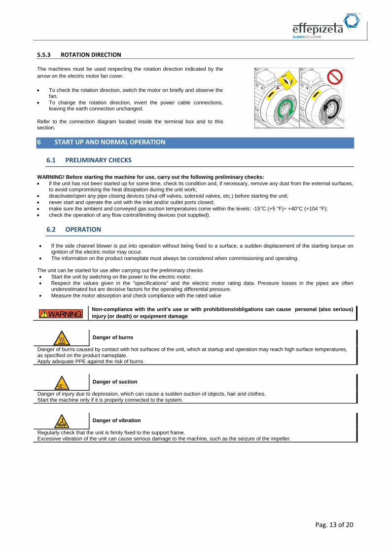
5.5.3 ROTATION DIRECTION
The machines must be used respecting the rotation direction indicated by the
arrow on the electric motor fan cover.
• To check the rotation direction, switch the motor on briefly and observe the fan.
• To change the rotation direction, invert the power cable connections, leaving the earth connection unchanged.
Refer to the connection diagram located inside the terminal box and to this section.
6 START UP AND NORMAL OPERATION
6.1 PRELIMINARY CHECKS
WARNING! Before starting the machine for use, carry out the following preliminary checks:
• if the unit has not been started up for some time, check its condition and, if necessary, remove any dust from the external surfaces, to avoid compromising the heat dissipation during the unit work;
• deactivate/open any pipe closing devices (shut-off valves, solenoid valves, etc.) before starting the unit;
• never start and operate the unit with the inlet and/or outlet ports closed;
• make sure the ambient and conveyed gas suction temperatures come within the levels: -15°C (+5 °F)÷ +40°C (+104 °F);
• check the operation of any flow control/limiting devices (not supplied).
6.2 OPERATION
• If the side channel blower is put into operation without being fixed to a surface, a sudden displacement of the starting torque on ignition of the electric motor may occur.
• The information on the product nameplate must always be considered when commissioning and operating.
The unit can be started for use after carrying out the preliminary checks
• Start the unit by switching on the power to the electric motor.
• Respect the values given in the "specifications" and the electric motor rating data. Pressure losses in the pipes are often underestimated but are decisive factors for the operating differential pressure.
• Measure the motor absorption and check compliance with the rated value
Non-compliance with the unit’s use or with prohibitions/obligations can cause personal (also serious)
injury (or death) or equipment damage
Danger of burns
Danger of burns caused by contact with hot surfaces of the unit, which at startup and operation may reach high surface temperatures, as specified on the product nameplate. Apply adequate PPE against the risk of burns.
Danger of suction
Danger of injury due to depression, which can cause a sudden suction of objects, hair and clothes. Start the machine only if it is properly connected to the system.
Danger of vibration
Regularly check that the unit is firmly fixed to the support frame. Excessive vibration of the unit can cause serious damage to the machine, such as the seizure of the impeller.
Pag. 14 of 20
6.3 STOPPING
• The unit must be stopped by switching off the power supply to the motor.
• On shutdown, make sure to operate the unit with open outlet (suction / delivery) for about 20 minutes. This operation allows the
removal of any condensation inside.
Danger due to noise
Some machines can produce loud noise, even over 80 dB (A). Reference levels are shown on the table of characteristic data that does not consider environmental reverb. Warning to be taken: Measure the acoustic pressure of the machine in the installation environment. In the case of levels above the threshold defined by local standards:
• report the noise hazard
• prepare the use of PPE
• isolate the environment
Danger of ejection of objects
• Danger due to exceeding performance levels that may cause seizure of the impeller. Check that operating conditions are in accordance with values declared on the nameplate. Avoid operating with the inlet and/or outlet ports closed even temporarily. Install a limit valve or equivalent circuit that can avoid excessive vacuum and / or overpressure and allow the compliance with levels shown on the product plate
• Danger of injury due to objects and fluids aspirated and thrown at high speed (injury to the skin or eyes). Only start the unit (first start) if it is properly connected and check it accurately. In the case of unusual noise from the impeller, switch off the unit immediately and check it accurately.
Danger of injury to upper limbs
During the start-up (first start) phase due to a combination of hazards, the risk of injury to upper limbs may arise.
Danger of sudden leakage and/or aspiration of fluids (even harmful ones)
They could cause damage to the respiratory system due to the leakage of gas while the unit is in use and/or the slowing down of connection to the gas flow circuit.
Danger due to a limited view of the place in which the unit is installed.
Make sure you always have the unit installed in your sight while carrying out any activities close to it.
Pag. 15 of 20
7 MAINTENANCE
In order to prevent faults and damage it is important to check periodically the units in operation; therefore it is advisable to adopt a
maintenance plan in line with this manual, providing for:
• periodical checks;
• periodical maintenance.
7.1 MAINTENANCE AND FAILURE CONDITIONS
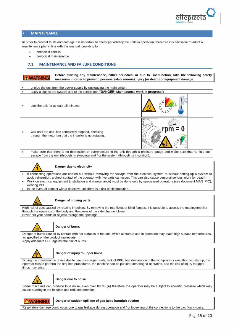
• unplug the unit from the power supply by unplugging the main switch;
• apply a sign to the system and to the control unit “DANGER! Maintenance work in progress";
• cool the unit for at least 15 minutes;
• wait until the unit has completely stopped, checking through the motor fan that the impeller is not rotating;
• make sure that there is no depression or overpressure in the unit through a pressure gauge and make sure that no fluid can
escape from the unit (through its stopping) and / or the system (through its insulation).
Before starting any maintenance, either periodical or due to malfunction, take the following safety
measures in order to prevent personal (also serious) injury (or death) or equipment damage:
Danger due to electricity
• If connecting operations are carried out without removing the voltage from the electrical system or without setting up a system to avoid reinsertion, a direct contact of the operator with live parts can occur. This can also cause personal serious injury (or death).
• Work on electrical equipment (installation and maintenance) must be done only by specialized operators (see document MAN_PIC), wearing PPE.
• In the event of contact with a defective unit there is a risk of electrocution.
Danger of moving parts
High risk of cuts caused by rotating impellers. By removing the manifolds or blind flanges, it is possible to access the rotating impeller through the openings of the body and the cover of the side channel blower. Never put your hands or objects through the openings.
Danger of burns
Danger of burns caused by contact with hot surfaces of the unit, which at startup and in operation may reach high surface temperatures, as specified on the product nameplate. Apply adequate PPE against the risk of burns.
Danger of injury to upper limbs
During the maintenance phase due to use of improper tools, lack of PPE, bad illumination of the workplace or unauthorized startup, the operator fails to perform the required procedures, the machine can be put into unmanaged operation, and the risk of injury to upper limbs may arise.
Danger due to noise
Some machines can produce loud noise, even over 80 dB (A) therefore the operator may be subject to acoustic pressure which may cause buzzing in the headset and reduced attention.
Danger of sudden spillage of gas (also harmful) suction
Respiratory damage could occur due to gas leakage during operation and / or loosening of the connections to the gas flow circuits.
Pag. 16 of 20
7.2 PERIODICAL CHECKS
In order to avoid any defects that may directly or indirectly cause damage, it is important that the unit is inspected by specialized
operators (see document MAN_PIC).
A) When the unit is running, routinely carry out the following checks:
• delivery temperature;
• operating pressure and/or vacuum;
• electric motor current absorption;
• vibrations;
• state of the filter and related load loss.
Changes to normal working conditions (power ups, abnormal noise, vibrations, excessive overheating of the service fluid) are indications that the units is not working properly. B) With the unit stopped and cooled, periodically carry out the following checks:
• dust: check and remove deposits from the external surfaces of the unit;
• suction filter (if fitted): every 10-15 days, check and clean or replace the filter cartridge. The dirty cartridge creates strong suction resistance and consequently a higher pressure differential, power absorption and operating temperature;
• for unit supplied with elastic joint, check the condition of the elastic joint as indicated in its operating manual;
• condensation discharge (if present): every 8-10 days, turn the yellow valve counterclockwise 90° to allow draining of the condensation that has built up inside the blower;
• check for oil leaks (TMD version) near the joint; if leaks are found, maintenance work must be scheduled to replace the seals.
7.3 ROUTINE MAINTENANCE REPAIR OF BREAKDOWNS
See the following chapter “TROUBLESHOOTING” for identifying possible critical situations and types of breakdowns. Always disconnect the unit and remove it from the plant to do routine maintenance, cleaning and replacing components and in the event of a breakdown.
7.4 LIFESPAN OF BEARINGS
Under normal operating conditions, the bearings of the unit must be replaced by a specialized operator (see document MAN_PIC), after
a time fixed by the manufacturer (see details in the table below).
Non Atex Blower 25000 hours or 3 years Atex Blower 18000 hours or 3 years
7.5 DISMANTLING AND DEMOLITION
Danger of seizure of the impeller due to excess vibration. Vibrations above the threshold (see table below) are considered NOT eligible and can cause damage to the machine and consequently personal injury even serious (or death) and / or damage to things. In the event of unusual noise and / or vibration over parameters, that may indicate the possibility the impeller is seizing up, turn off the unit immediately.
Class I ( Blower with electric motor of power ≤15kW ) Class II ( Blower with electric motor of power >15kW )
a > 2,2 a > 3,5
a = effective vibration speed level [mm/s]
Danger due to residual overpressure or drop in pressure:
• with residual overpressure, process fluids can leak, with the risk of injury to the skin and eyes;
• with a drop in pressure there is the risk that hair and clothes can be trapped;
• disconnect the unit only after closing and bleeding the system connected to it.
Replace the bearings of the unit only if you have all the instructions, the parts list and the section/explosion of
the unit
Danger of crushing and / or impacting various parts of the body
During the dismantling and demolition phases due to the sudden drop or displacement of the packaging, there may be a risk of crushing
and / or impacting various parts of the body. During work around the unit, the operator may fall due to stumbling or slipping.
Pag. 17 of 20
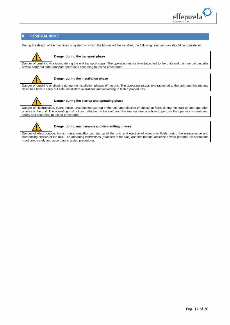
8 RESIDUAL RISKS
During the design of the machines or system on which the blower will be installed, the following residual risks should be considered.
Danger during the transport phase
Danger of crushing or slipping during the unit transport steps. The operating instructions (attached to the unit) and this manual describe how to carry out safe transport operations according to tested procedures.
Danger during the installation phase
Danger of crushing or slipping during the installation phases of the unit. The operating instructions (attached to the unit) and this manual describes how to carry out safe installation operations and according to tested procedures.
Danger during the startup and operating phase
Danger of electrocution, burns, noise, unauthorized startup of the unit, and ejection of objects or fluids during the start-up and operation phases of the unit. The operating instructions (attached to the unit) and this manual describe how to perform the operations mentioned safely and according to tested procedures.
Danger during maintenance and dismantling phases
Danger of electrocution, burns, noise, unauthorized startup of the unit, and ejection of objects or fluids during the maintenance and dismantling phases of the unit. The operating instructions (attached to the unit) and this manual describe how to perform the operations mentioned safely and according to tested procedures.
Pag. 18 of 20
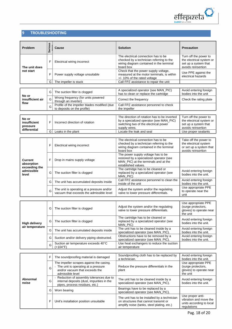
9 TROUBLESHOOTING
Problem S
eri
ou
s
ne
ss
Cause Solution Precaution
The unit does not start
F Electrical wiring incorrect
The electrical connection has to be checked by a technician referring to the wiring diagram contained in the terminal board box
Turn off the power to the electrical system or set up a system that avoids reinsertion
F Power supply voltage unsuitable Check that the power supply voltage, measured at the motor terminals, is within +/- 10% of the rated voltage
Use PPE against the electrical hazards
G The impeller is stuck Call FPZ assistance to repair the unit
No or insufficient air flow
G The suction filter is clogged A specialized operator (see MAN_PIC) has to clean or replace the cartridge
Avoid entering foreign bodies into the unit
G Wrong frequency (for units powered through an inverter)
Correct the frequency Check the rating plate
G Profile of the impeller blades modified (due to deposits on the profile)
Call FPZ assistance personnel to check the impeller
No or insufficient pressure differential
F Incorrect direction of rotation
The direction of rotation has to be inverted by a specialized operator (see MAN_PIC) switching two of the electrical power supply wires.
Turn off the power to the electrical system or set up a system that avoids reinsertion
G Leaks in the plant Locate the leak and seal Use proper sealants
Current absorption exceeding the admissible level
F Electrical wiring incorrect
The electrical connection has to be checked by a technician referring to the wiring diagram contained in the terminal board box
Take off the power to the electrical system or set up a system that avoids reinsertion
F Drop in mains supply voltage
The power supply voltage has to be restored by a specialized operator (see MAN_PIC) at the terminals and at the established values.
G The suction filter is clogged The cartridge has to be cleaned or replaced by a specialized operator (see MAN_PIC)
Avoid entering foreign bodies into the unit.
G The unit has accumulated deposits inside Call FPZ assistance personnel to clean the inside of the unit
Avoid entering foreign bodies into the unit.
G The unit is operating at a pressure and/or vacuum that exceeds the admissible level
Adjust the system and/or the regulating valve to lower pressure differentials.
Use appropriate PPE to operate near the unit
High delivery air temperature
G The suction filter is clogged Adjust the system and/or the regulating valve to lower pressure differentials.
Use appropriate PPE (surge protectors, gloves) to operate near the unit
G The suction filter is clogged The cartridge has to be cleaned or replaced by a specialized operator (see MAN_PIC)
Avoid entering foreign bodies into the unit.
G The unit has accumulated deposits inside The unit has to be cleaned inside by a specialized operator (see MAN_PIC).
Avoid entering foreign bodies into the unit.
G Suction and/or delivery piping obstructed. Obstructions have to be removed by a specialized operator (see MAN_PIC).
Avoid entering foreign bodies into the unit.
G Suction air temperature exceeds 40°C (+104°F)
Use heat exchangers to reduce the suction air temperature
Abnormal noise
F The soundproofing material is damaged Soundproofing cloth has to be replaced by a technician.
Avoid entering foreign bodies into the unit.
G
The impeller scrapes against the casing. Reduce the pressure differentials in the plant
Use appropriate PPE (surge protectors, gloves) to operate near the unit
- The unit is operating at a pressure and/or vacuum that exceeds the admissible level
G - Reduction of assembly tolerances due to
internal deposits (dust, impurities in the pipes, process residues, etc.)
The unit has to be cleaned inside by a specialized operator (see MAN_PIC).
Avoid entering foreign bodies into the unit.
G Worn bearing Bearings have to be replaced by a specialized operator (see MAN_PIC).
F Unit’s installation position unsuitable The unit has to be installed by a technician on structures that cannot transmit or amplify noise (tanks, steel plating, etc.)
Use proper anti-vibration and move the units according to local regulations
Pag. 19 of 20
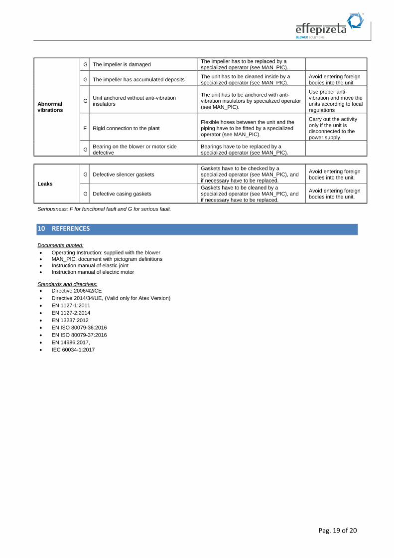
Abnormal vibrations
G The impeller is damaged The impeller has to be replaced by a specialized operator (see MAN_PIC).
G The impeller has accumulated deposits The unit has to be cleaned inside by a specialized operator (see MAN_PIC).
Avoid entering foreign bodies into the unit
G Unit anchored without anti-vibration insulators
The unit has to be anchored with anti-vibration insulators by specialized operator (see MAN_PIC).
Use proper anti-vibration and move the units according to local regulations
F Rigid connection to the plant Flexible hoses between the unit and the piping have to be fitted by a specialized operator (see MAN_PIC).
Carry out the activity only if the unit is disconnected to the power supply.
G Bearing on the blower or motor side defective
Bearings have to be replaced by a specialized operator (see MAN_PIC).
Leaks
G Defective silencer gaskets Gaskets have to be checked by a specialized operator (see MAN_PIC), and if necessary have to be replaced.
Avoid entering foreign bodies into the unit.
G Defective casing gaskets Gaskets have to be cleaned by a specialized operator (see MAN_PIC), and if necessary have to be replaced.
Avoid entering foreign bodies into the unit.
Seriousness: F for functional fault and G for serious fault.
10 REFERENCES
Documents quoted:
• Operating Instruction: supplied with the blower
• MAN_PIC: document with pictogram definitions
• Instruction manual of elastic joint
• Instruction manual of electric motor
Standards and directives:
• Directive 2006/42/CE
• Directive 2014/34/UE, (Valid only for Atex Version)
• EN 1127-1:2011
• EN 1127-2:2014
• EN 13237:2012
• EN ISO 80079-36:2016
• EN ISO 80079-37:2016
• EN 14986:2017,
• IEC 60034-1:2017
Pag. 20 of 20
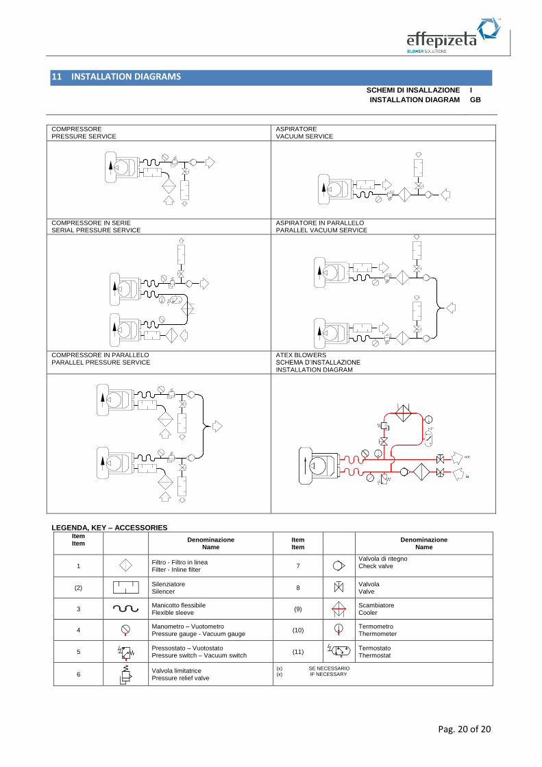
11 INSTALLATION DIAGRAMS
SCHEMI DI INSALLAZIONE I
INSTALLATION DIAGRAM GB
COMPRESSORE PRESSURE SERVICE
ASPIRATORE VACUUM SERVICE
COMPRESSORE IN SERIE SERIAL PRESSURE SERVICE
ASPIRATORE IN PARALLELO PARALLEL VACUUM SERVICE
COMPRESSORE IN PARALLELO PARALLEL PRESSURE SERVICE
ATEX BLOWERS SCHEMA D’INSTALLAZIONE INSTALLATION DIAGRAM
LEGENDA, KEY – ACCESSORIES Item Item
Denominazione Name
Item Item
Denominazione
Name
1
Filtro - Filtro in linea Filter - Inline filter
7
Valvola di ritegno Check valve
(2)
Silenziatore Silencer
8
Valvola Valve
3
Manicotto flessibile Flexible sleeve
(9)
Scambiatore Cooler
4
Manometro – Vuotometro Pressure gauge - Vacuum gauge
(10)
Termometro Thermometer
5
Pressostato – Vuotostato Pressure switch – Vacuum switch
(11)
Termostato Thermostat
6
Valvola limitatrice Pressure relief valve
(x) SE NECESSARIO (x) IF NECESSARY