Embed Size (px)
Citation preview
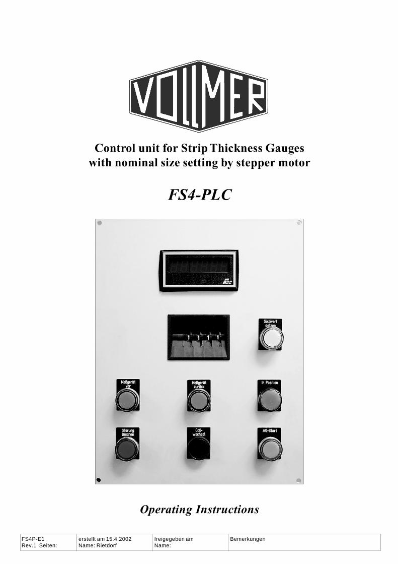
Control unit for Strip Thickness Gaugeswith nominal size setting by stepper motor
�������
Operating Instructions
FS4P-E1 erstellt am 15.4.2002 freigegeben am BemerkungenRev.1 Seiten: Name: Rietdorf Name:
� ������� ������������� ������ FS4P-e1
�������� �� � ��� ���� �� ��� ���� �� ��� ���� � �� � ��������� �
Content page
Intended use of this machine ......................................................................... 2
Safety Precautions, please read carefully! ................................................... 3
Design and function ....................................................................................... 4
Start-up and repairs ........................................................................................ 7
Operation ........................................................................................................ 8
Nominal size selection / setting ......................................................... 8
Safety note ........................................................................................... 8
On strip motion of the gauge ............................................................. 9
Errors ................................................................................................. 10
Error messages .................................................................................. 10
Off strip motion of the gauge ........................................................... 11
Automatic zero adjustment A0 ........................................................ 12
Coil change ........................................................................................ 12
Service mode ..................................................................................... 12
Automatic symmetry adjustment .................................................... 13
Quick off strip (optional) ................................................................. 13
Notes ............................................................................................................ 14
Subject to change without prior notice
Intended use of this machine
This gauge must be used exclusively as a control unit for the individualVollmer gauge it has be designed for and adapted to by the Vollmer compa-ny. It must be firmly installed in its intended position and electrically andelectronically connected as intended by the Vollmer company. Any altera-tion might cause severe damage.
������������� ������ �������FS4P-e1
FRIEDRICH VOLLMER��������������� ����������������� ���������� ����� ������������������� ����� !����������"�
Safety Precautions, please read carefully!
This manual has to be handed to the machine operator, and one copy mustbe permanently available to operator and service personnel. Nobody is al-lowed to work on or with this gauge, before he has read and understood thismanual. Feel free to call the Vollmer company in case of any questions (phone+49 2334 507 0). In addition, the operator has to read the instruction man-uals for the other Vollmer devices, such as the VMF amplifier and the thicknessgauge. They are part of the entire documentation and they contain safetyrelevant information which might not be included in this manual..
Check if the voltage on the model label is the same as the main supply volt-age. Never connect the product to any power supply which has a differentvoltage than on the model label.
Warning , Crushing Hazard ! In many applications, this gauge has a hy-draulic traverse unit. Such traversing units are very powerful and mightcause severe injury. Before operating this device, you must read the safetyprecautions in the operating instructions manual of the gauge ! The gaugecontrol system has to be switched to the mode 'Service I', before anybodyenters the danger zone close to the gauge. When operating in the standardmode ('Service 0') the gauge might rush back or forward unexpected anduncontrollable.
Attention, risk of mechanical damage! Enter a new nominal value only aslong as the gauge head is in the rear limit position. The gauge and or the millmight become severely damaged if a new nominal thickness value is readinto the control electronics as long as the gauge is on strip or as long as themill`s thickness control is in operation.
Do not perform any manipulations on this product not described in this manual.Wrong handling might cause hazards for the user, and it terminates the in-strument warranty period.
This product may only be used if it is in a technically perfect condition. Anychanges or defects which might affect the safety must be eliminated beforethe product is put into operation.
Expose this product only to such environmental conditions as it is designedfor. Stick to the notes in the technical documentation. This product is notdesigned for use in wet environments. Do not use this product in explosionhazardous areas.
Before putting this product into operation and regularly during operation,check this product for damage. Defects of all kinds must be eliminated atonce by authorized service personnel. The use of original spare parts and ofadditions from the manufacturer reduce the security hazard.
Never operate this product if any cover is open or removed. Check all con-nections regularly and replace defective parts immediately.
Caution! Crush-ingHazard by thetraversing deviceof the gaugehead !
Before operatingthis device, youmust read thesafety precautionsin the operatinginstructionsmanual of thegauge !
� ������� ������������� ������ FS4P-e1
�������� �� � ��� ���� �� ��� ���� �� ��� ���� � �� � ��������� �
Design and function
The FS4-PLC unit is a programmable control unit for Vollmer gauges, suchas strip thickness gauges, gap sensors or position sensors on mills. In thefollowing only strip thickness gauges are mentioned in order to make thereading easier.
Each of the controlled gauges has one Vollmer measurement transducer whichsposition may be shifted to different nominal size positions by a stepper motor.This is done to extend the measurement range of the gauge since the trans-ducer itself has only a stroke of one or two millimetres, depending on thetransducer type. The nominal size position to which the transducer has beenshifted by the stepper motor forms a reference position and is not alteredduring the actual measurement. The transducer measures only the differ-ence to this set nominal value.
The different nominal values within a rolling program are usually automat-ically read into the FS4-PLC from an external control stand. However, it ispossible to enter such data manually.
The FS4-PLC controls the stepper motor which shifts the transducer to theselected nominal size. This is done by means of a high precision steppermotor and high precision spindles without any feedback from the measure-ment ram. The ram will not touch the material surface unless the gauge is inmeasurement position and a strip is in the mill.
During the measurement, the VMF measurement amplifier indicates thedifference between the measured actual thickness and the nominal size. Thethickness data (together with additional data) are available on the outputsof the VMF amplifier. The functions of the gauge and of the connected VMFamplifier are described in separate manuals. These manuals are part of theVollmer documentation.
There are several gauge control keys on the control panel of the FS4-PLC.All these functions may be selected from external sources as well.
Because the FS4-control unit features many parameters which may be seton site, it can be adjusted to meet virtually every individual situation. TheFS4-PLC is an important element for the high reliability of the Vollmermeasurement and control systems for strip processing machines.
������������� ������ �������FS4P-e1
FRIEDRICH VOLLMER��������������� ����������������� ���������� ����� ������������������� ����� !����������"�
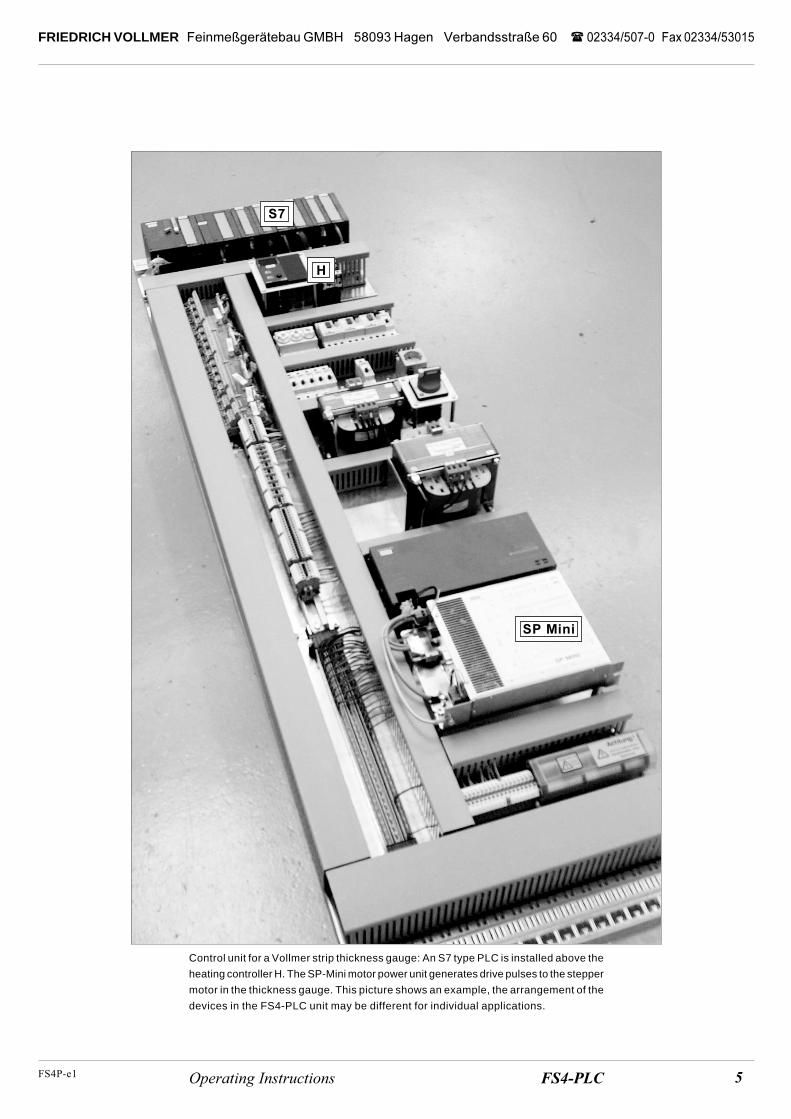
Control unit for a Vollmer strip thickness gauge: An S7 type PLC is installed above the
heating controller H. The SP-Mini motor power unit generates drive pulses to the stepper
motor in the thickness gauge. This picture shows an example, the arrangement of the
devices in the FS4-PLC unit may be different for individual applications.
��
�������
�
� ������� ������������� ������ FS4P-e1
�������� �� � ��� ���� �� ��� ���� �� ��� ���� � �� � ��������� �
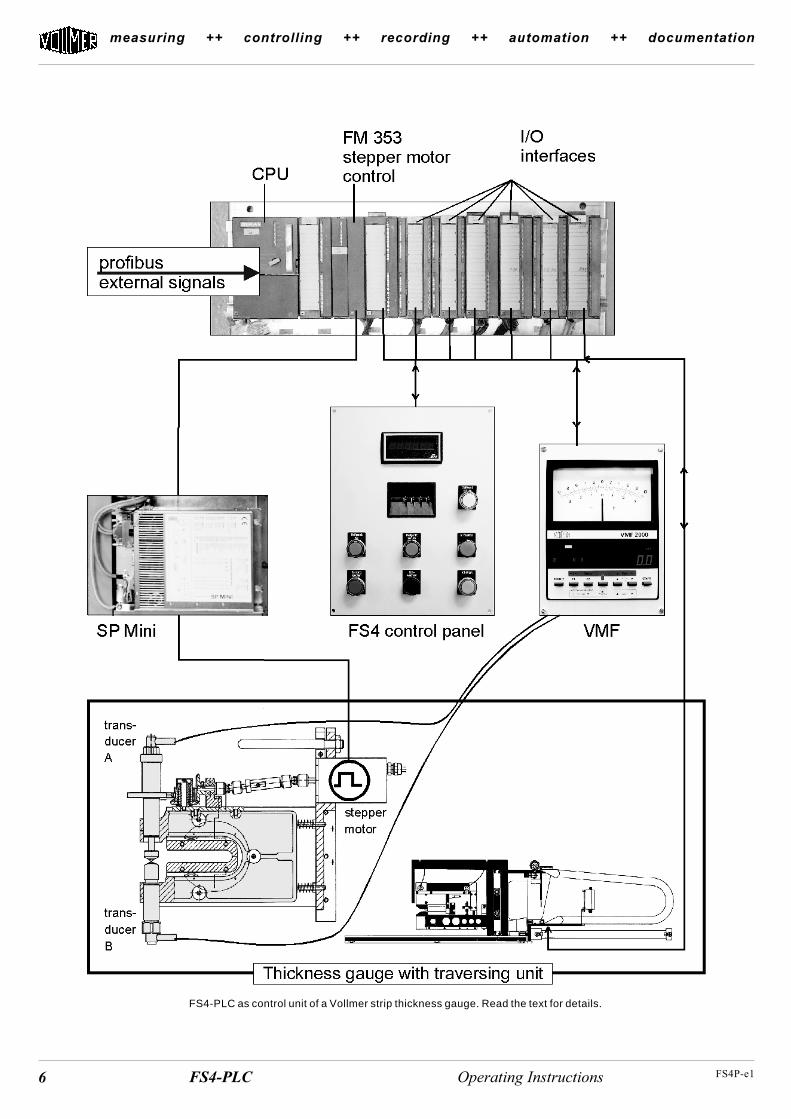
FS4-PLC as control unit of a Vollmer strip thickness gauge. Read the text for details.
�������������� ������ �������FS4P-e1
FRIEDRICH VOLLMER��������������� ����������������� ���������� ����� ������������������� ����� !����������"�
The sketch on the left shows the general design of the FS4-PLC control:The profibus feeds external signals into the S7. The CPU converts such sig-nals so that they can be passed on by the interfaces, e.g. for traversing thegauge head back or forth. In addition, the S7 generates the signals for theVMF amplifier and the SP-Mini.
Such commands may be entered at an external control stand and are trans-ferred by the profibus or they may be entered manually at the FS4-PLC`scontrol panel.
The VMF amplifier sums up the signals of the two transducers and passesthe measurement value to the S7.
The SP-Mini generates drive pulses for the stepper motor which shifts theadjustable transducer to the position of the selected nominal size.
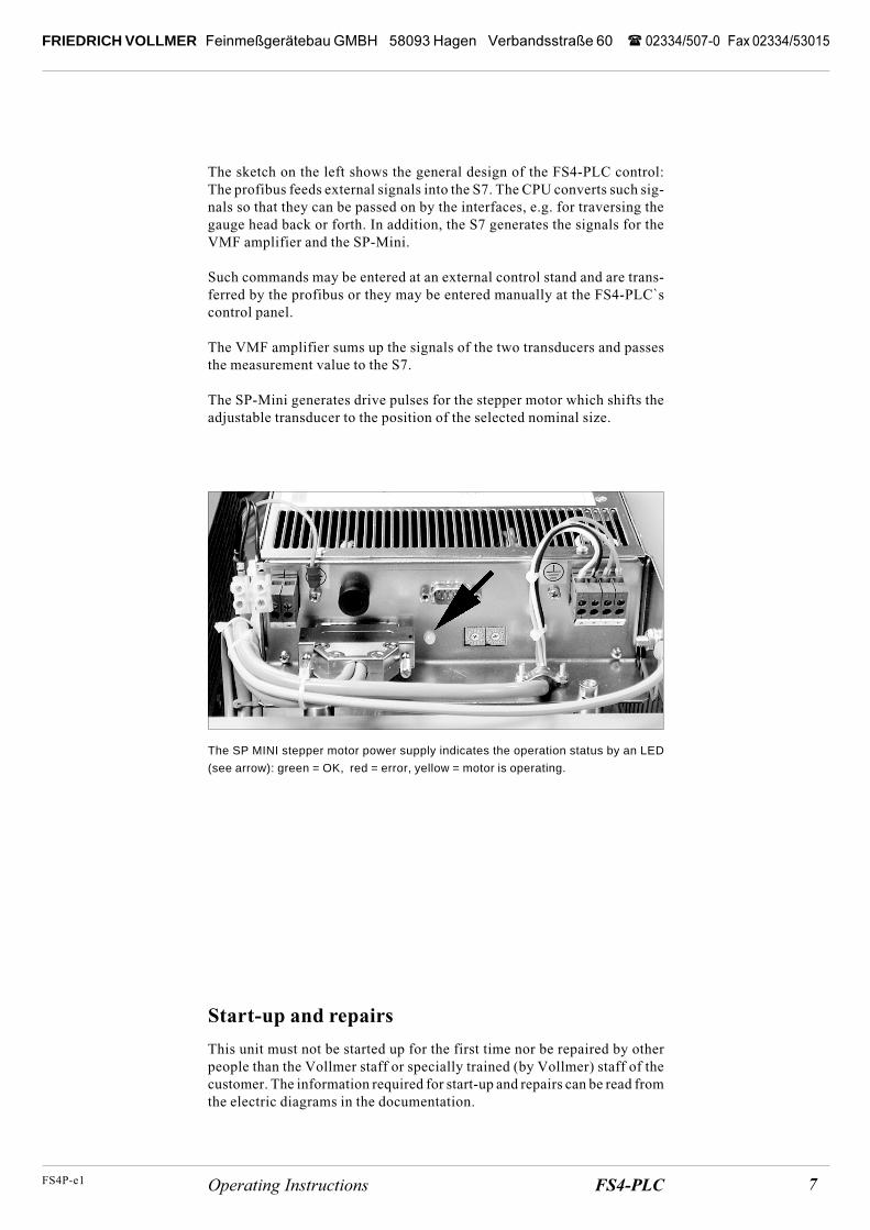
The SP MINI stepper motor power supply indicates the operation status by an LED
(see arrow): green = OK, red = error, yellow = motor is operating.
Start-up and repairs
This unit must not be started up for the first time nor be repaired by otherpeople than the Vollmer staff or specially trained (by Vollmer) staff of thecustomer. The information required for start-up and repairs can be read fromthe electric diagrams in the documentation.
������� ������������� ������ FS4P-e1
�������� �� � ��� ���� �� ��� ���� �� ��� ���� � �� � ��������� �
Operation
The functions described in this section may be activated either manually atthe control panel of the FS4-PLC or by external signals.
Nominal size selection / setting
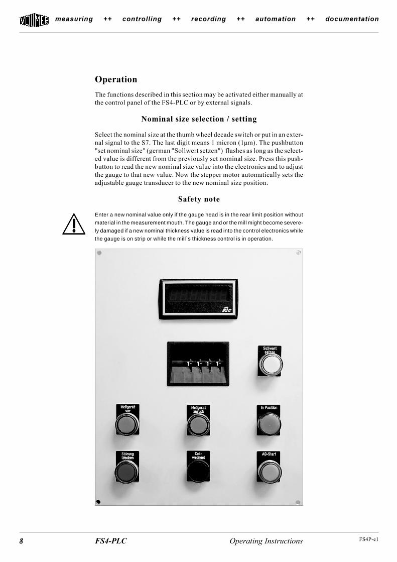
Select the nominal size at the thumb wheel decade switch or put in an exter-nal signal to the S7. The last digit means 1 micron (1µm). The pushbutton"set nominal size" (german "Sollwert setzen") flashes as long as the select-ed value is different from the previously set nominal size. Press this push-button to read the new nominal size value into the electronics and to adjustthe gauge to that new value. Now the stepper motor automatically sets theadjustable gauge transducer to the new nominal size position.
Safety note
Enter a new nominal value only if the gauge head is in the rear limit position without
material in the measurement mouth. The gauge and or the mill might become severe-
ly damaged if a new nominal thickness value is read into the control electronics while
the gauge is on strip or while the mill`s thickness control is in operation.
�������������� ������ �������FS4P-e1
FRIEDRICH VOLLMER��������������� ����������������� ���������� ����� ������������������� ����� !����������"�
On strip motion of the gauge
This pushbutton is active if all conditions are fulfilled to enable the gaugetraversing towards the strip.
The thickness gauge can be moved on strip under the following conditions:- no signal „emergency stop“- signal „strip tension“ is OK- no error signal from the pneumatic pressure detector- no error signal from the limit switch in the gauge`s measurement mouth- no error in the zero adjustment cycle A0- light barrier is open- service mode switch is set to "Service 0"
The thickness gauge is moved onto the strip by pressing the „on strip“ push-button. The following functions are operated:
- magnetic valve „thickness gauge on strip“ is switched on (gauge movesforwards and lamp „on strip“ flashes slowly at a rate of one flash persecond)
- the two magnetic valves for diamond lifting, "DAV top“ and "DAVbottom", are switched on (measurement tips of the upper and lower transducerare pneumatically pulled in)
- light barrier signals, that the gauge has reached the strip edge(infrared light beam is interrupted)
0,1 to 10 seconds (adjustable) after the light barrier was interrupted, thefollowing functions are operated:
- magnetic valve „thickness gauge on strip“ is switched off (gauge stops)
- the two magnetic valves for diamond lifting, "DAV top" and DAV bot-tom" are switched off (the measurement pressure springs in the trans-ducers push the measurement tips of the upper and lower transducer againstthe strip surface)
- the magnetic valve „pneumatic guide rollers“ is switched on(upper guide rollers are pneumatically pushed down onto the strip withthe adjusted working pressure)
- the magnetic valve „pneumatic diamond cooling“ is switched on (com-pressed air is blown against the measurement tips)
- the control lamp „on strip“ goes on
- the signal „in position“, which enables the automatic control, is generat-ed after a short time period for stabilizing (e.g. 1.3 seconds); the lamp"in position" goes on.
Warning !
Crushing hazard
As long as somebody is in
the danger zone close to the
gauge, the gauge must be
operated in the Service mode.
No other operation mode is
allowed.
�� ������� ������������� ������ FS4P-e1
�������� �� � ��� ���� �� ��� ���� �� ��� ���� � �� � ��������� �
Errors
The gauge head is not enabled to be traversed forward if the light barrier isinterrupted when the gauge is in its rear limit position. The lamp in the „quiterror“ pushbutton flashes to indicate the error.
Other possible reasons for errors:
- rear limit switch is defective
- service function is on, i.e. the "service" switch is set to "I"
- signal „emergency stop“ is on
- light barrier is dirty or defective (cable)
- limit switch in the gauge measurement mouth is defective
- no feedback from the compressed air pressure detector
First eliminate the error reason(s) and then press "quit error". The lamp willonly go off if all error reasons were eliminated before.
Error messages
The digital indication shows an error code if an error occurs:
9001 error Sp Mini not ready
9001 error Sp Mini error
XXXX wrong input FM 353 (special error No.)
9004 data error FM 353
9005 reading error FM 353
9006 error VMF 2000 system not active
9007 error write command "speed" to FM 353
9008 error write command "enable regulator" to FM 353
9009 error write command "reference position" to FM 353
9010 error transducer holder not open during A0
9011 error motor moves to plus direction 1 mm
9012 error transducer control A0
9013 error transducer signal > 500µm
FM 353 means the positioning device (to control the stepper motor) in theS7-PLC.
��������������� ������ �������FS4P-e1
FRIEDRICH VOLLMER��������������� ����������������� ���������� ����� ������������������� ����� !����������"�
Off strip motion of the gauge
The thickness gauge moves off strip to its rear limit position, if:
- the „off strip“ pushbutton is pressed or
- „emergency stop“ is activated or
- the limit switch „measurement mouth“ is contacted by strip slipping awayto the side or
- strip tension breaks down
The following functions are operated after the signal „off strip“:
- control lamp "off strip" flashes
- feedback control is switched off immediately
- control lamp „in position“ goes out
- magnetic valves „pneumatic diamond cooling" and "pneumatic guiderollers" are switched off (the cooling air jet is switched off and the upperguide rollers are released from a portion of their pneumatic pressure
- the two magnetic diamond lifting valves „DAV top“ and DAV bottom"are switched on (measurement tips of the upper and lower transducerare pneumatically lifted off the strip)
- the magnetic valve „gauge off strip“ is switched on (gauge moves backand the control lamp in the „off strip“ pushbutton flashes slowly onceper second)
The following functions are operated after the gauge reached the rear limitposition switch :
- magnetic valve „gauge off strip“ is switched off (gauge stops in rearlimit position)
- control lamp „off strip“ turns to permanent light
- DAV is switched off (transducer tips contact each other)
�� ������� ������������� ������ FS4P-e1
�������� �� � ��� ���� �� ��� ���� �� ��� ���� � �� � ��������� �
Automatic zero adjustment A0
If the gauge is in the rear limit position, the A0 cycle can be started with"A0". Pressing of the „A0“ pushbutton (or external signal) starts these functions:
- A0 key starts to flash in 1 second strokes during the A0 cycle
- memory of the VMF measurement amplifier is erased by a pulse
- analogue value of the VMF amplifier is used to move the upper trans-ducer to zero
- motor stops within the tolerance window (a few microns + and minus tozero)
- VMF indicator is set to zero- FS4PLC counter is set to zero
- stepper motor moves the adjustable transducer to the last valid nominalsize
- A0 key stops flashing
The A0 cycle may also be performed with the gauge head in measurementposition (on strip). In that case the automatic strip thickness control is dis-abled for the duration of the A0 cycle. Pressing the A0 key makes the gaugemoving „off strip“ into the rear limit position. There the A0 cycle runs asusual. After the zero adjustment the thickness gauge moves back on stripand the strip thickness control is automatically enabled.
The „A0“ control lamp flashes if the system requires an A0 procedure, e.g.after Power On or after an error. No measurement is enabled unless a suc-cessful A0 cycle has been performed before.
Coil change
This signal terminates the data reading and starts the statistic evaluation forthe finished coil.
Service mode
Activating of the service mode (when all of the thickness gauges are in theirrear limit position), switches off the following functions:
- pneumatic diamond cooling
- diamond lifting system DAV
- strip tension monitoring
- pneumatic guide rollers
- measurement mouth limit switch
Regard the
Safety Notes
about the service mode
which are printed in the
Operating Instructions man-
ual of the strip thickness
gauge !
�������������� ������ �������FS4P-e1
FRIEDRICH VOLLMER��������������� ����������������� ���������� ����� ������������������� ����� !����������"�
- light barrier
- compressed air pressure detector
- emergency stop
Now the thickness gauge can be moved on and off strip by inching service.The service mode remains active (even if the service switch is turned off)until the gauge was brought to its rear limit position.
Automatic symmetry adjustment
Automatic symmetry adjustment can only be operated when the Servicemode is on. First set the gauge to the nominal size zero.
By switching „sym on“ this type of the FS4 PLC switches the pneumaticvalves for the diamond lifting alternating for the top and the bottom side.
A detailed description about the service mode and the automatic symmetryadjustment is in the Operating Instructions manual for the gauge and in theinstruction manual for the VMF amplifier.
Quick off strip (optional)
With this option the gauge is able to move back faster than in normal modebecause of an additional bypass valve. This function is activated in follow-ing situations:
- emergency stop is activated
- breakdown of strip tension
- measurement mouth limit switch has been actuated
�� ������� ������������� ������ FS4P-e1
�������� �� � ��� ���� �� ��� ���� �� ��� ���� � �� � ��������� �
Notes