Embed Size (px)
Citation preview
*e-mail: [email protected]
Creep-Age Forming of AA7475 Aluminum Panels for Aircraft Lower Wing Skin Application
Diego José Inforzatoa, Paulo Roberto Costa Juniora, Fernando Ferreira Fernandeza,
Dilermando Nagle Travessab*
aEmpresa Brasileira de Aeronáutica S.A. – Embraer, Av. Brigadeiro Faria Lima, 2170, CEP 12227-901, São José dos Campos, SP, Brasil
bDepartamento de Ciência e Tecnologia, Universidade Federal de São Paulo – UNIFESP, Rua Talim, 330, CEP 12231-380, São José dos Campos, Brasil
Received: November 7, 2011; Revised: May 3, 2012
Creep-age forming (CAF) is an interesting process for the airframe industry, as it is able to form or shape panels into smooth, but complex, curvatures. In the CAF process, the ageing cycle of the alloy is used to relax external loads imposed to the part, through creep mechanisms. Those relaxed stresses impose a new curvature to the part. At the end of the process, significant spring back (sometimes about 70%) is observed and the success in achieving the desired form depends on how the spring back can be predicted in order to compensate it by tooling changes. Most of the applications relate to simple (non stiffened) panels. The present work deals with the CAF of aluminum panels for aircraft wing skin application. CAF was performed using vacuum-bagging autoclave technique in small scale complex shape stiffened panels, machined from an AA7475 alloy plate. An analytical reference model from the literature was employed estimate the spring back effect in such panel geometry. This model that deals with simple plates was adapted to stiffened panels using a geometric simplification, resulting in a semi-empirical model. The results demonstrate that CAF is a promising process to form stiffened panels, and the spring back can be roughly estimated through a simple model and few experiments.
Keywords: creep-age forming, spring back, semi-empirical modeling, AA7475 alloy
1. IntroductionCreep-age forming (CAF) is a process that combines
two metallurgical phenomena, creep and precipitation hardening, in order to form a metallic part. Both phenomena are highly dependent on temperature and time. The CAF process is very interesting for the aerospace industry, mainly to form large-contoured wing skins, which presents smooth curvatures on both wing span and wing chord directions. In this case, flat panels can be machined from thinner gauge plates, resulting in cost reductions related to material and machining time. On the other hand, wings having severe dihedral angle, mainly in lower skins, can demand double curvature surfaces in narrow regions, increasing the complexity of the forming process.
Some of the examples of CAF application to form upper wing panels include1,2 the B1B and Hawk bombers, the executive jet Gufstream G-IV and the commercial Airbus jets A330 and A340, as well as the A380. This late is the biggest commercial aircraft in operation, demanding very big parts and structures and in this case, CAF process made feasible the manufacturing of the upper wing skin in lesser parts, as no aeronautical grade alloys were available in the necessary gauge to machine the curved panel in a single piece. All of these examples, however, are related to non-stiffened panels (no stringers integrated to the skin), including only localized thickness reductions optimizing
the part weight. There are no examples of CAF application on complex stiffened panels.
In the CAF process, the part to be formed is initially forced against a tooling which has a desired curvature, through clamping mechanisms or vacuum-bagging autoclave techniques. In this first step, the forces imposed are below the yielding limit of the material. Subsequent heating starts a stress-induced deformation process that allows the material to simultaneously relax these external forces through creep mechanisms and to age by precipitation hardening. The creep mechanism introduces some permanent deformation in the material. At the final stage, the part is cooled and, as the external load is removed, part of the contour is lost due to the spring back. The magnitude of the spring back is considerable, reaching about 40 up to 70% of the imposed initial curvature1.
When comparing to other forming processes for wing panels, CAF results in parts with lower residual stresses, resulting in a better fatigue performance1. Furthermore, CAF is able to form panels into the smooth curvatures that are typical for wing applications, including double curvatures (cell shapes). The process is very reproducible. One of the challenges of the process for wing skin forming relates to the metallurgy of the alloy, which shall result in a product having good strength and toughness after the creep-age cycle. Moreover, the desired curvature can only be precisely achieved if the spring back can be anticipated, enabling
OI:D 10.1590/S1516-14392012005000080Materials Research. 2012; 15(4): 596-602 © 2012
Creep-Age Forming of AA7475 Aluminum Panels for Aircraft Lower Wing Skin Application
the tooling to compensate (by over-curving) the elastic return. Modeling the spring back is a quite complex task, mainly in stiffened panels that are very stiff and have abrupt thicknesses transitions2. The material properties are transient during the process, as the precipitation hardening progresses, giving an additional complexity to the modeling task. Several attempts have been made in order to model the CAF process. Simple mathematic/phenomenological models3
or complex FEM (finite elements modeling) have been developed, mainly related to simple plates having a constant thickness. Those models usually employ equilibrium relations, as well as constitutive equations to describe the creep behavior of the material. Constitutive equations that combine creep and precipitation hardening simultaneously have been established for the AA7010 aluminum alloy4. Those equations were subsequently employed in a FEM to model thick plates with double curvature5. Using this model, the authors report that it is possible to estimate the effect of the plate thickness and process time on the spring back magnitude.
The use of CAF process to shape aircraft wing skin panels demands the use of alloys that exhibit high relaxation rates combined with high strength and toughness after the forming cycle. Fatigue and fatigue crack-growth behavior of the alloy is critical for lower skin wing panels, commonly resulting in the selection of AA2XXX series alloys, in the natural aged temper (T351). Those alloys are not suitable for creep-age forming, as in their artificial aged condition (T6 or T8 tempers), higher strength develops at the expense of the toughness and fatigue-crack growth resistance. New AA2XXX alloys with additions of Li, Zr and SC are also being developed specifically for CAF application6. In these alloys, the addition of Li (from 0,5 to 1,6 wt%) increases the damage tolerance of the alloy after ageing, while Zr and Sc stabilizes the microstructure and enhance the stress relaxation capability by creeping. The commercially available AA7475 alloy can also be a good alternative for creep-age formed lower wing skins, as it is frequently used in the overaged condition, resulting in a good combination of strength, toughness and stress corrosion cracking resistance7. In addition, the overaged temper (T73) of the AA7475 alloy shows an interesting process window for creep-age forming, as the recommended overaging procedure consists in a two step cycle of 6 to 8 hours at 121 °C followed by 24 to 30 hours at 163 °C8,9. It has been observed that in the second ageing step, the relaxation rate is higher due to the dissolution of GP zones formed in the first step, nucleating the metastable η’ that indicates the initiation of the overaging process10. Further, the relaxation rate of this alloy is appreciable when the CAF applied load is higher than 30% of the yielding strength at the temperature10. From this behavior, it can also be observed that spring back will always be present in the CAF process. Its similarity to the simple bending condition results in the presence of a neutral line that is a consequence of the equilibrium state. In the neutral line and close to it, the stresses are close to zero and consequently the CAF process will have no effect in this region.
In the presented context, the present work deals with the application of the CAF process to shape complex
stiffened panels for lower wing skin applications. The CAF is performed simultaneously to the second stage of overaging of the AA7475 aluminum alloy, using a vacuum-bagging autoclave process. Further, an analytical reference model existing in the literature is used to estimate the spring back of the panels. This reference model was adapted to the case of a stiffened panel by geometric considerations and the creep-age modeling was replaced by a calibration using the final deflection of real parts, resulting in a semi-empirical model. The semi-empirical model offers a simple and cost effective form of roughly estimate the spring back, as it does not depend on complex material testing or FEM and can be calibrated by few experiments. The results are also discussed in the light of the equivalent thickness (height) approach for the model and its use to predict the spring back.
2. Experimental Setup
2.1. Materials and forming process
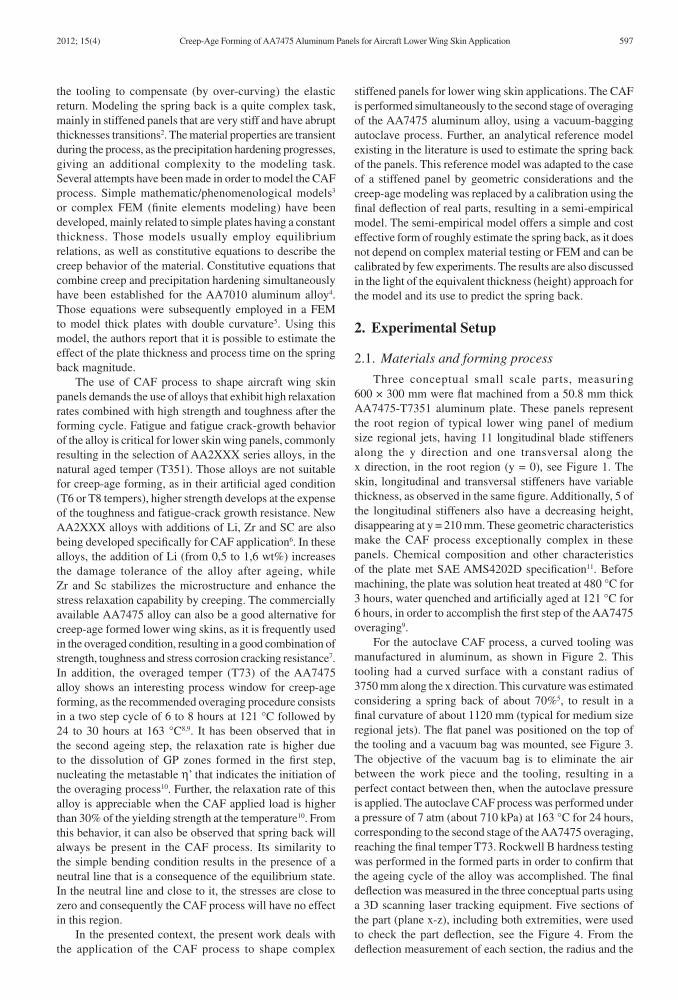
Three conceptual small scale parts, measuring 600 × 300 mm were flat machined from a 50.8 mm thick AA7475-T7351 aluminum plate. These panels represent the root region of typical lower wing panel of medium size regional jets, having 11 longitudinal blade stiffeners along the y direction and one transversal along the x direction, in the root region (y = 0), see Figure 1. The skin, longitudinal and transversal stiffeners have variable thickness, as observed in the same figure. Additionally, 5 of the longitudinal stiffeners also have a decreasing height, disappearing at y = 210 mm. These geometric characteristics make the CAF process exceptionally complex in these panels. Chemical composition and other characteristics of the plate met SAE AMS4202D specification11. Before machining, the plate was solution heat treated at 480 °C for 3 hours, water quenched and artificially aged at 121 °C for 6 hours, in order to accomplish the first step of the AA7475 overaging9.
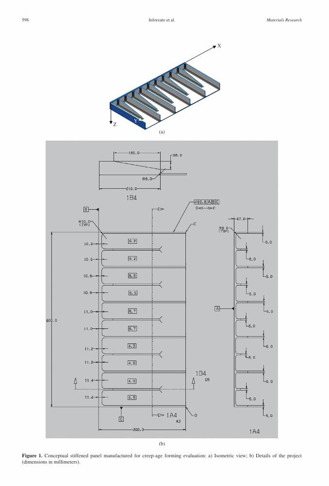
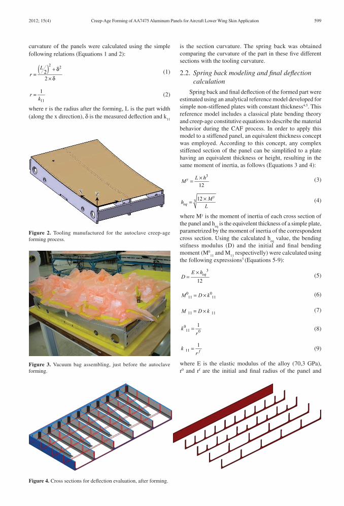
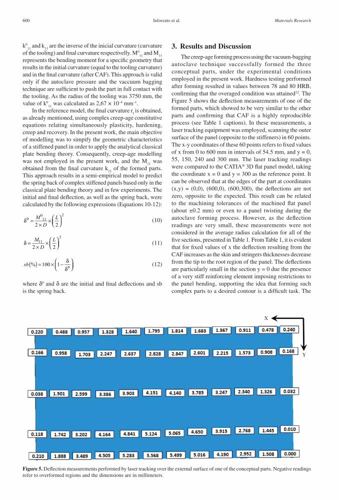
For the autoclave CAF process, a curved tooling was manufactured in aluminum, as shown in Figure 2. This tooling had a curved surface with a constant radius of 3750 mm along the x direction. This curvature was estimated considering a spring back of about 70%5, to result in a final curvature of about 1120 mm (typical for medium size regional jets). The flat panel was positioned on the top of the tooling and a vacuum bag was mounted, see Figure 3. The objective of the vacuum bag is to eliminate the air between the work piece and the tooling, resulting in a perfect contact between then, when the autoclave pressure is applied. The autoclave CAF process was performed under a pressure of 7 atm (about 710 kPa) at 163 °C for 24 hours, corresponding to the second stage of the AA7475 overaging, reaching the final temper T73. Rockwell B hardness testing was performed in the formed parts in order to confirm that the ageing cycle of the alloy was accomplished. The final deflection was measured in the three conceptual parts using a 3D scanning laser tracking equipment. Five sections of the part (plane x-z), including both extremities, were used to check the part deflection, see the Figure 4. From the deflection measurement of each section, the radius and the
2012; 15(4) 597
Inforzato et al.
Figure 1. Conceptual stiffened panel manufactured for creep-age forming evaluation: a) Isometric view; b) Details of the project (dimensions in millimeters).
598 Materials Research
Creep-Age Forming of AA7475 Aluminum Panels for Aircraft Lower Wing Skin Application
is the section curvature. The spring back was obtained comparing the curvature of the part in these five different sections with the tooling curvature.
2.2. Spring back modeling and final deflection calculation
Spring back and final deflection of the formed part were estimated using an analytical reference model developed for simple non-stiffened plates with constant thickness4,5. This reference model includes a classical plate bending theory and creep-age constitutive equations to describe the material behavior during the CAF process. In order to apply this model to a stiffened panel, an equivalent thickness concept was employed. According to this concept, any complex stiffened section of the panel can be simplified to a plate having an equivalent thickness or height, resulting in the same moment of inertia, as follows (Equations 3 and 4):
3
12y L hM ×= (3)
3 12 y
eqMh
L×= (4)
where My is the moment of inertia of each cross section of the panel and h
eq is the equivelent thickness of a simple plate,
parametrized by the moment of inertia of the correspondent cross section. Using the calculated h
eq value, the bending
stifness modulus (D) and the initial and final bending moment (M0
11 and M
11 respectivelly) were calculated using
the following expressions5 (Equations 5-9):
3
12eqE h
D×
= (5)
0 011 11M D k= ×
(6)
11 11M D k= × (7)
=011 0
1kr
(8)
=111fk
r (9)
where E is the elastic modulus of the alloy (70,3 GPa), r0 and rf are the initial and final radius of the panel and
Figure 2. Tooling manufactured for the autoclave creep-age forming process.
Figure 4. Cross sections for deflection evaluation, after forming.
Figure 3. Vacuum bag assembling, just before the autoclave forming.
curvature of the panels were calculated using the simple following relations (Equations 1 and 2):
( )2 222
+ δ=
× δ
Lr (1)
=11
1rk (2)
where r is the radius after the forming, L is the part width (along the x direction), δ is the measured deflection and k
11
2012; 15(4) 599
Inforzato et al.
k011
and k11
are the inverse of the inicial curvature (curvature of the tooling) and final curvature respectivelly. M0
11 and M
11
represents the bending moment for a specific geometry that results in the initial curvature (equal to the tooling curvature) and in the final curvature (after CAF). This approach is valid only if the autoclave pressure and the vaccuum bagging technique are sufficient to push the part in full contact with the tooling. As the radius of the tooling was 3750 mm, the value of k0
11 was calculated as 2,67 × 10⁻⁴ mm–1.
In the reference model, the final curvature rf is obtained,
as already mentioned, using complex creep-age constitutive equations relating simultaneously plasticity, hardening, creep and recovery. In the present work, the main objective of modelling was to simpify the geometric characteristics of a stiffened panel in order to apply the analytical classical plate bending theory. Consequently, creep-age modelling was not employed in the present work, and the M
11 was
obtained from the final curvature k11
of the formed parts. This approach results in a semi-empirical model to predict the spring back of complex stiffened panels based only in the classical plate bending theory and in few experiments. The initial and final deflection, as well as the spring back, were calculated by the following expressions (Equations 10-12):
200 11
2 2M L
D δ = × ×
(10)
211
2 2M L
D δ = × × (11)
( ) 0% 100 1sb δ = × − δ (12)
where δ0 and δ are the initial and final deflections and sb is the spring back.
3. Results and DiscussionThe creep-age forming process using the vacuum-bagging
autoclave technique successfully formed the three conceptual parts, under the experimental conditions employed in the present work. Hardness testing performed after forming resulted in values between 78 and 80 HRB, confirming that the overaged condition was attained12. The Figure 5 shows the deflection measurements of one of the formed parts, which showed to be very similar to the other parts and confirming that CAF is a highly reproducible process (see Table 1 captions). In these measurements, a laser tracking equipment was employed, scanning the outer surface of the panel (opposite to the stiffeners) in 60 points. The x-y coordinates of these 60 points refers to fixed values of x from 0 to 600 mm in intervals of 54.5 mm, and y = 0, 55, 150, 240 and 300 mm. The laser tracking readings were compared to the CATIA® 3D flat panel model, taking the coordinate x = 0 and y = 300 as the reference point. It can be observed that at the edges of the part at coordinates (x,y) = (0,0), (600,0), (600,300), the deflections are not zero, opposite to the expected. This result can be related to the machining tolerances of the machined flat panel (about ±0.2 mm) or even to a panel twisting during the autoclave forming process. However, as the deflection readings are very small, these measurements were not considered in the average radius calculation for all of the five sections, presented in Table 1. From Table 1, it is evident that for fixed values of x the deflection resulting from the CAF increases as the skin and stringers thicknesses decrease from the tip to the root region of the panel. The deflections are particularly small in the section y = 0 due the presence of a very stiff reinforcing element imposing restrictions to the panel bending, supporting the idea that forming such complex parts to a desired contour is a difficult task. The
Figure 5. Deflection measurements performed by laser tracking over the external surface of one of the conceptual parts. Negative readings refer to overformed regions and the dimensions are in millimeters.
600 Materials Research
Creep-Age Forming of AA7475 Aluminum Panels for Aircraft Lower Wing Skin Application
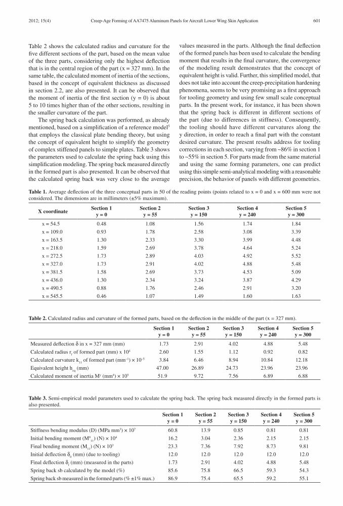
Table 2 shows the calculated radius and curvature for the five different sections of the part, based on the mean value of the three parts, considering only the highest deflection that is in the central region of the part (x = 327 mm). In the same table, the calculated moment of inertia of the sections, based in the concept of equivalent thickness as discussed in section 2.2, are also presented. It can be observed that the moment of inertia of the first section (y = 0) is about 5 to 10 times higher than of the other sections, resulting in the smaller curvature of the part.
The spring back calculation was performed, as already mentioned, based on a simplification of a reference model5 that employs the classical plate bending theory, but using the concept of equivalent height to simplify the geometry of complex stiffened panels to simple plates. Table 3 shows the parameters used to calculate the spring back using this simplification modeling. The spring back measured directly in the formed part is also presented. It can be observed that the calculated spring back was very close to the average
values measured in the parts. Although the final deflection of the formed panels has been used to calculate the bending moment that results in the final curvature, the convergence of the modeling result demonstrates that the concept of equivalent height is valid. Further, this simplified model, that does not take into account the creep-precipitation hardening phenomena, seems to be very promising as a first approach for tooling geometry and using few small scale conceptual parts. In the present work, for instance, it has been shown that the spring back is different in different sections of the part (due to differences in stiffness). Consequently, the tooling should have different curvatures along the y direction, in order to reach a final part with the constant desired curvature. The present results address for tooling corrections in each section, varying from ~86% in section 1 to ~55% in section 5. For parts made from the same material and using the same forming parameters, one can predict using this simple semi-analytical modeling with a reasonable precision, the behavior of panels with different geometries.
Table 1. Average deflection of the three conceptual parts in 50 of the reading points (points related to x = 0 and x = 600 mm were not considered. The dimensions are in millimeters (±5% maximum).
X coordinateSection 1
y = 0Section 2
y = 55Section 3y = 150
Section 4y = 240
Section 5y = 300
x = 54.5 0.48 1.08 1.56 1.74 1.84
x = 109.0 0.93 1.78 2.58 3.08 3.39
x = 163.5 1.30 2.33 3.30 3.99 4.48
x = 218.0 1.59 2.69 3.78 4.64 5.24
x = 272.5 1.73 2.89 4.03 4.92 5.52
x = 327.0 1.73 2.91 4.02 4.88 5.48
x = 381.5 1.58 2.69 3.73 4.53 5.09
x = 436.0 1.30 2.34 3.24 3.87 4.29
x = 490.5 0.88 1.76 2.46 2.91 3.20
x = 545.5 0.46 1.07 1.49 1.60 1.63
Table 2. Calculated radius and curvature of the formed parts, based on the deflection in the middle of the part (x = 327 mm).
Section 1y = 0
Section 2y = 55
Section 3y = 150
Section 4y = 240
Section 5y = 300
Measured deflection δ in x = 327 mm (mm) 1.73 2.91 4.02 4.88 5.48
Calculated radius rf of formed part (mm) x 104 2.60 1.55 1.12 0.92 0.82
Calculated curvature k11
of formed part (mm–1) × 10–5 3.84 6.46 8.94 10.84 12.18
Equivalent height heq
(mm) 47.00 26.89 24.73 23.96 23.96
Calculated moment of inertia My (mm4) × 105 51.9 9.72 7.56 6.89 6.88
Table 3. Semi-empirical model parameters used to calculate the spring back. The spring back measured directly in the formed parts is also presented.
Section 1y = 0
Section 2y = 55
Section 3y = 150
Section 4y = 240
Section 5y = 300
Stiffness bending modulus (D) (MPa mm3) × 107 60.8 13.9 0.85 0.81 0.81
Initial bending moment (M011
) (N) × 104 16.2 3.04 2.36 2.15 2.15
Final bending moment (M11
) (N) × 103 23.3 7.36 7.92 8.73 9.81
Initial deflection δ0 (mm) (due to tooling) 12.0 12.0 12.0 12.0 12.0
Final deflection δf (mm) (measured in the parts) 1.73 2.91 4.02 4.88 5.48
Spring back sb calculated by the model (%) 85.6 75.8 66.5 59.3 54.3
Spring back sb measured in the formed parts (% ±1% max.) 86.9 75.4 65.5 59.2 55.1
2012; 15(4) 601
Inforzato et al.
4. ConclusionsBased on the results obtained in the present work, the
following conclusions can be presented:• Thesimplificationofthereferencemodel,including
the equivalent height concept was valid for the AA7475 aluminum alloy, under the forming conditions employed in this work. The classical plate bending theory could be applied and the deflections experimentally measured could adequately calibrate the semi-empirical model;
• The spring back was observed to be stronglydependent on the stiffness and moment of inertia of each section, being higher as higher the stiffness;
• This simplified model can be used to estimate thespring back of panels having different reinforcement geometries, if a trial is performed using few conceptual panels from the same material and under the same process parameters; and
• Inthepresentwork,itwasobservedthatthecreep-ageforming process can be employed to form complex stiffened panels. The spring back estimation showed that tooling should have different curvatures along the y direction, in order to result in a homogeneous curvature.
References1. Holman MC. Autoclave age forming large aluminum
aircraf t panels . Journal of Mechanical Working Te ch n o l og y . 1 9 8 9 ; 2 0 : 4 7 7 - 4 8 8 . h t t p : / / d x . d o i .org/10.1016/0378-3804(89)90055-7
2. Brewer H. Age forming integrally stiffened aluminum aerospace structures in anautoclave. In Proceedings of the Aircraft Design, Systems and Operations Conference; 1989; Seattle. Edimet Spa; 1989. p. 6-8.
3. Narimetla SP, Peddieston J and Buchanan GR. A simple unified age forming model. Materials Research Communications. 2000; 27:631-636. http://dx.doi.org/10.1016/S0093-6413(00)00139-7
4. Ho KC, Lin J and Dean TA. Constitutive modelling of primary creep for age forming an aluminium alloy. Journal of Materials Processing Technology. 2004; 153-154:122-127. http://dx.doi.org/10.1016/j.jmatprotec.2004.04.304
5. Jeunechamps PP, Ho KC, Lin J, Ponthot JP and Dean TA. A closed form technique to predict springback in creep age-forming. International Journal of Mechanical Sciences. 2006; 48:621-629. http://dx.doi.org/10.1016/j.ijmecsci.2006.01.005
6. Starink MJ, Gao N, Kamp N, Wang SC, Pitcher PD and Sinclair I. Relations between microstructure, precipitation, age-formability and damage tolerance of Al-Cu-Mg-Li
(Mn, Zr, Sc) alloys for age forming. Materials Science and Engineering. 2006; A48:241-249.
7. Oliveira Junior AF, De Barros MC, Cardoso KR and Travessa DN. The effect of RRA on the strength and SCC resistance on AA7050 and AA7150 aluminium alloys. Materials Science & Engineering. 2004; A379:321-326.
8. Society of Automobile Engineers – SAE. AMS 2770H: Heat Treatment of Wrought Aluminum Alloy Parts. SAE International; 2006.
9. Society of Automobile Engineers – SAE. AMS 2772E: Heat Treatment of Aluminum Alloy Raw Materials. SAE International; 2008.
10. Robey RF, Prangnell PB and Dif RA. A Comparison of the Stress Relaxation Behaviour of Three Aluminium Aerospace Alloys for use in Age-Forming Applications. Materials Forum. 2004; 28:132-138.
11. Society of Automobile Engineers – SAE. AMS 4202D: Aluminum Alloy Plate 5.7Zn - 2.2Mg - 1.6Cu - 0.22Cr (7475-T7351) Solution Heat Treated, Stress Relieved by Stretching, and Precipitation Heat Treated - UNS A97475. SAE International; 2005.
12. Society of Automobile Engineers – SAE. AMS 2658C: Hardness and Conductivity Inspection of Wrought Aluminum Alloy Parts. SAE International; 2009.
602 Materials Research