Embed Size (px)
Citation preview

8/3/2019 dandotiya_berglund
http://slidepdf.com/reader/full/dandotiyaberglund 1/3
The Bergforsk Annual Meeting, 5 May 2011
Increased production systems effectivenessthrough condition monitoring and prognostics
Rajiv Dandotiya,FilipBerglund LuleåUniversity of Technology Optimum maintenance of mill liners
Miningindustriesusesheavy‐duty equipment thatmustwork around theclock inhighly
abrasiveenvironments.Autogenous(AG)millsusedintheminingindustryandoredressing
plants are examples of major bottlenecks in the context of downtime concerning theproductioneconomy.Rubberlinersinsidethemillarecriticalcomponentinthecontextof
shellprotectionandoregrinding.Replacementandinspectionsofthemilllinersaremajor
factorsregardingmillstoppagesandcorrespondingproductionlossesduetomillstoppage.
ThepresentresearchpresentstheusefulnessofLifeCycleCost(LCC)andLifeCycleProfit
(LCP) analyses for the mill liners of the mining industries and demonstrates decision
modelsforeffectivemaintenanceplanning.Theresearchispresentedintwoparts.Part 1 dealswithoptimum replacement interval for group replacementofmill liners. It
brieflydescribestheinterrelationbetweenmaintenanceandprocessparameters.Thestudy
showstheimpactofmaintenancestrategiesongrindingprocesswhichleadstosignificant
savingsofthemill.Thephysicalexplanationofeachparameter(power,metaloutput,liner
wear,inspectionpolicy,oredensity,torqueetc)isprovidedtogiveindepthpictureof theeffect of maintenance decisions on the process economy. Based on the knowledge and
interactionbetweentheseparameters,amathematicalmodelforLCPhasbeendeveloped
foroptimizingoptimumreplacementintervalofgroupofmillliners.Thepresentresearch
simulatedtheLCPmodelfordifferentoretypesandoptimumreplacementintervalforthe
replacementofmilllinersisobtained.Theresultsofthisstudyobservedsignificantsavings
whensuggestedmaintenancepolicyisintroduced.SeeFigure1
Profit fraction Vs Optimum replacement interval
0,965
0,97
0,975
0,98
0,985
0,99
0,995
1
1,005
0 100 200 300 400
Optimum replacement interval (days)
P r o f i t f r a c t i o n
290
Figure1.Profit fractionversusoptimumreplacement interval

8/3/2019 dandotiya_berglund
http://slidepdf.com/reader/full/dandotiyaberglund 2/3
The Bergforsk Annual Meeting, 5 May 2011
Part2dealswithdetailedanalysisofmilldowntimeasitfocusedatmillstopsduetomajorandminorreplacementofmillliners.Thereasonsofmultiplestopsareduetodifferentlife
cycleperiodofdifferentpartsofmillliners.Thisminorstopnotonlyleadstoproduction
lossesduringreplacementbutalso leads to losseswhichoccur duringstartuptime.The
replacementofallpartsofthemilllinersalltogetherisnotpossibleduetotechnicaland
economicalreasons.TheaimofthisstudyistominimizetheLCCbyoptimizingthegrouping
forjointreplacementandwear lifeperiodofdifferentparts ofmill liners.Theoptimized
maintenance decisions are basedon the tradeoff analysis betweenmonetary savings by
reductionofmillstopsandthecostincurredforimprovingthelifeofthepartofthemill
liners.Dynamicprogramminghasbeenusedtodeterminethelifecyclecost(LCC)foreach
feasiblescenarioformaintenancescheduling forvarious life improvementsof mill liners
parts. The scenario with minimum LCC provides the optimum grouping for joint
replacementand necessary life improvement of different partsofmill liners. The resultshowsthatanoptimumlifeimprovementcanfurtherreducetheLCC.Ademonstratorhas
beendevelopedformakingthesecosteffectivemaintenancedecisions.
Condition monitoring of fatigue cracks in rotating mining millsInfrared thermography and fatigue damage sensors have been investigated as non
destructivetestingmethodsforhealthmonitoringofrotatingminingmills.Theideaofthe
thermography method is to monitor the thermal differences on the mill surface with
thermalcamerain ordertodetectandmaintaincracksandothermaterialdamagein the
millmaterial.Figure2showthermalimagestakenduringoperationonacrackedmillhead.
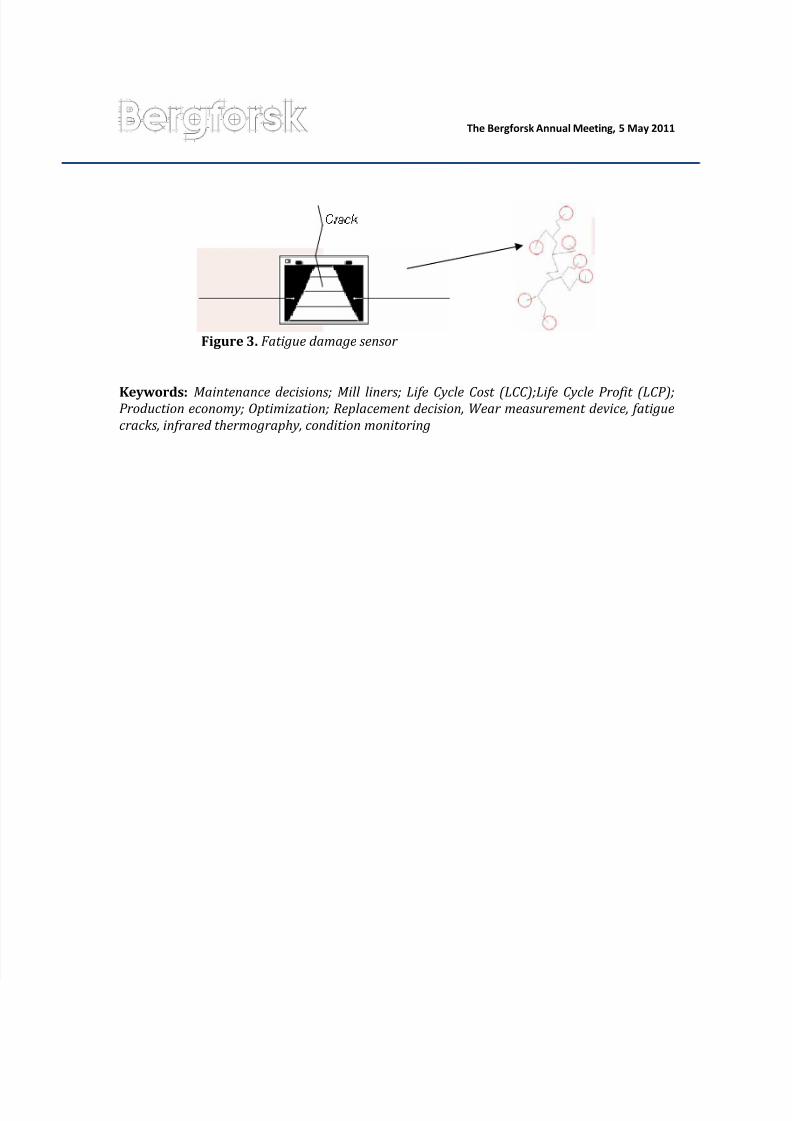
The fatigue damage sensors are attached to the tips of a fatigue crack andmeasure its
propagation.Thesensorsconsistofthinconductivewireswhichbreakoneaftertheother
as the crackpropagates through the sensor, see Figure 3. To test the usefulness of the
methods, real lifemeasurementswith IR‐camera and fatigue damage sensors have been
performedon theminingmills atLKABdressingplants.Preliminaryresults indicate that
infraredthermographyisafast,easyandrelativelycheapinspectionmethodwhichcanfind
and monitor fatigue cracks and material damage in rotating mining mills. The fatigue
damagesensorsmeasuretherealcrackpropagationbutarenoteasytoplaceduotowiring
and connectivity setup. The large and fast propagating cracks together with the harsh
miningenvironmentmakethemethodnotsuitableformonitoringofmills
Figure2.Thermal imagesof amill head,crack free portiontotheleft and cracked portiontotheright
8/3/2019 dandotiya_berglund
http://slidepdf.com/reader/full/dandotiyaberglund 3/3
The Bergforsk Annual Meeting, 5 May 2011
Figure3.Fatiguedamagesensor
Keywords:Maintenancedecisions;Mill liners;LifeCycleCost (LCC);LifeCycleProfit (LCP);Productioneconomy;Optimization;Replacement decision,Wear measurement device, fatiguecracks,infrared thermography,conditionmonitoring


