Embed Size (px)
Citation preview

T.C.
MİLLÎ EĞİTİM BAKANLIĞI
DENİZCİLİK
GÜVERTE - MANEVRA
(MESLEKİ İNGİLİZCE)
Ankara, 2017
Bu materyal, Mesleki ve Teknik Eğitim Okul/Kurumları’nda uygulanan Çerçeve
Öğretim Programları’nda yer alan yeterlikleri kazandırmaya yönelik olarak
öğrencilere rehberlik etmek amacıyla hazırlanmış bireysel öğrenme materyalidir.
Millî Eğitim Bakanlığınca ücretsiz olarak verilmiştir.
PARA İLE SATILMAZ.
i
EXPLANATIONS .................................................................................................................. iii INTRODUCTION .................................................................................................................... 1 LEARNING ACTIVITY–1 ...................................................................................................... 3 1. SAFETY ON BOARD ......................................................................................................... 3
1.1. Safety Equipments On Board ........................................................................................ 3 1.1.1. Head protection ...................................................................................................... 4 1.1.2. Hearing protection ................................................................................................. 4 1.1.3. Face and eye protection ......................................................................................... 5 1.1.4. Respiratory protective equipment .......................................................................... 5 1.1.5. Hand and foot protection ....................................................................................... 7 1.1.6. Protection from falls .............................................................................................. 7 1.1.7. Body protection ..................................................................................................... 7 1.1.8. Protection against drowning .................................................................................. 8
1.2. Check List of Safety at Sea ........................................................................................... 8 1.2.1. Steps Of Personal Safety ....................................................................................... 8 1.2.2. Check Your Ship ................................................................................................... 9 1.2.3. Check Lists And Forms ....................................................................................... 11
APPLICATION ACTIVITY.............................................................................................. 14 MEASURING AND EVALUATION ............................................................................... 15
LEARNING ACTIVITY–2 .................................................................................................... 16 2. SHIP MAINTENANCE ..................................................................................................... 16
2.1. Maintenance On Board ............................................................................................... 16 2.2. Planned Maintenance System ..................................................................................... 18 2.3. Dry Dock ..................................................................................................................... 22
2.3.1. Types of dry dock ................................................................................................ 22 APPLICATION ACTIVITY.............................................................................................. 25 MEASURING AND EVALUATION ............................................................................... 26
LEARNING ACTIVITY–3 .................................................................................................... 27 3. NAUTICAL CHARTS AND PUBLICATIONS ............................................................... 27
3.1.1. Chart General Information Block ........................................................................ 27 3.1.2. Lines of Latitude and Longitude .......................................................................... 28 3.1.3. Soundings and Fathom Curves ............................................................................ 29 3.1.4. Location of the Compass Rose ............................................................................ 29 3.1.5. Location of the Distance Scales ........................................................................... 29
3.2. Nautical Publications .................................................................................................. 29 3.2.1. List of Lights and Fog Signals ............................................................................. 30 3.2.2. List of Radio Signals ........................................................................................... 30 3.2.3. Sailing Directions ................................................................................................ 31 3.2.4. Tide Tables .......................................................................................................... 31 3.2.5. Tidal Stream Atlases ............................................................................................ 31 3.2.6. Manual of Tides ................................................................................................... 31 3.2.7. Tidal Handbooks .................................................................................................. 31 3.2.8. The Mariners Handbook (NP100) ....................................................................... 32 3.2.9. Nautical Almanac ................................................................................................ 32 3.2.10. The International Code of Signals ..................................................................... 32 3.2.11. IAMSAR Manual: Mobile Facilities ................................................................. 33
CONTENT
ii
3.2.12. Notice To Mariners ............................................................................................ 33 3.2.13. The annual summary of notices to mariners ...................................................... 34
APPLICATION ACTIVITY.............................................................................................. 35 MEASURING AND EVALUATION ............................................................................... 36
LEARNING ACTIVITY–4 .................................................................................................... 37 4. METEOROLOGY.............................................................................................................. 37
4.1. General Meteorology .................................................................................................. 37 4.1.1. Meteorology ......................................................................................................... 37 4.1.2. Synoptic Meteorology ......................................................................................... 40 4.1.3. Weather Instruments ............................................................................................ 41
4.2. Weather Terms and Abbrevations ............................................................................... 42 4.2.1. Weather Terms .................................................................................................... 42 4.2.2. Weather Abbrevations ......................................................................................... 43 4.2.3. Table of Symbols ............................................................................................ 44
4.3. Radiofacsimile Symbols And Contractions ............................................................ 45 APPLICATION ACTIVITY.............................................................................................. 46 MEASURING AND EVALUATION ............................................................................... 47
LEARNING ACTIVITY–5 .................................................................................................... 48 5. EMERGENCY SITUATIONS AT SEA ............................................................................ 48
5.1. Types of Emergency ................................................................................................... 48 5.1.1. Ship Collision ...................................................................................................... 48 5.1.2. Ship Grounding .................................................................................................... 49 5.1.3. Capsizing ............................................................................................................. 49 5.1.4. Fire and Explosion ............................................................................................... 49 5.1.5. Maritime Piracy ................................................................................................... 50 5.1.6. Man Overboard .................................................................................................... 51
5.2. Accident Prevention Precautions ................................................................................ 51 5.2.1. Personal Protective Equipment ............................................................................ 51 5.2.2. Pre-Use Equipment Check ................................................................................... 51 5.2.3. Precautions against fire and explosion................................................................. 52 5.2.4. Electric Welding Equipment ................................................................................ 52 5.2.5. Precautions To Be Taken During Electric Arc Welding ..................................... 54 5.2.6. Compressed Gas Cylinders .................................................................................. 54 5.2.7. Gas Welding And Cutting ................................................................................... 55
APPLICATION ACTIVITY.............................................................................................. 57 MEASURING AND EVALUATION ............................................................................... 58
MODULE EVALUATION .................................................................................................... 59 ANSWER KEY ...................................................................................................................... 62 REFERENCES ....................................................................................................................... 65
iii
EXPLANATIONS
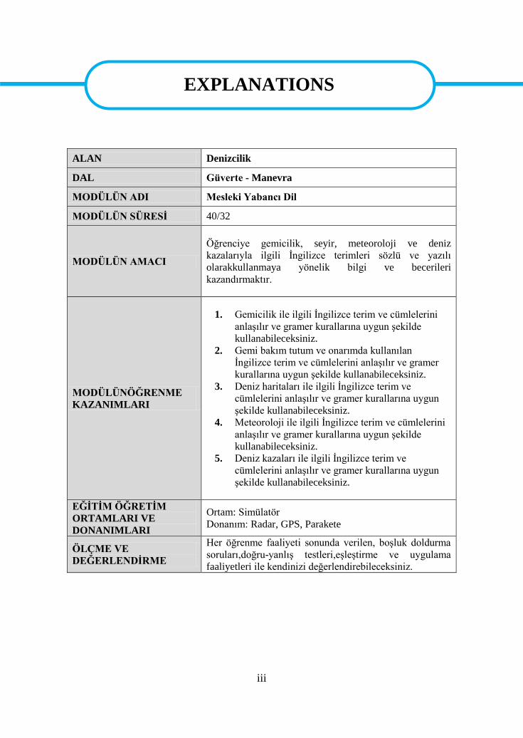
ALAN Denizcilik
DAL Güverte - Manevra
MODÜLÜN ADI Mesleki Yabancı Dil
MODÜLÜN SÜRESİ 40/32
MODÜLÜN AMACI
Öğrenciye gemicilik, seyir, meteoroloji ve deniz
kazalarıyla ilgili İngilizce terimleri sözlü ve yazılı
olarakkullanmaya yönelik bilgi ve becerileri
kazandırmaktır.
MODÜLÜNÖĞRENME
KAZANIMLARI
1. Gemicilik ile ilgili İngilizce terim ve cümlelerini
anlaşılır ve gramer kurallarına uygun şekilde
kullanabileceksiniz.
2. Gemi bakım tutum ve onarımda kullanılan
İngilizce terim ve cümlelerini anlaşılır ve gramer
kurallarına uygun şekilde kullanabileceksiniz.
3. Deniz haritaları ile ilgili İngilizce terim ve
cümlelerini anlaşılır ve gramer kurallarına uygun
şekilde kullanabileceksiniz.
4. Meteoroloji ile ilgili İngilizce terim ve cümlelerini
anlaşılır ve gramer kurallarına uygun şekilde
kullanabileceksiniz.
5. Deniz kazaları ile ilgili İngilizce terim ve
cümlelerini anlaşılır ve gramer kurallarına uygun
şekilde kullanabileceksiniz.
EĞİTİM ÖĞRETİM
ORTAMLARI VE
DONANIMLARI
Ortam: Simülatör
Donanım: Radar, GPS, Parakete
ÖLÇME VE
DEĞERLENDİRME
Her öğrenme faaliyeti sonunda verilen, boşluk doldurma
soruları,doğru-yanlış testleri,eşleştirme ve uygulama
faaliyetleri ile kendinizi değerlendirebileceksiniz.
EXPLANATIONS

iv
1
INTRODUCTION Dear students,
Foreign language is known to be important in every field of sector in the present day.
In the field of maritime it is still more important. Knowledge of vocational terms is
important not only in native language but also in other languages as well. This module
enables you to reach the technical English you may in your field.
INTRODUCTION

2
3
LEARNING ACTIVITY–1
You are going to learn the terms of safety equipments on board
Check the safety equipments on board by visiting a ship and port
1. SAFETY ON BOARD
1.1. Safety Equipments On Board
Safety of self and co-workers is the prime priority kept in mind by a professional
seafarer while working on board ship. All shipping companies ensure that their crew follow
personal safety procedures and rules for all the operation carried on board ships.
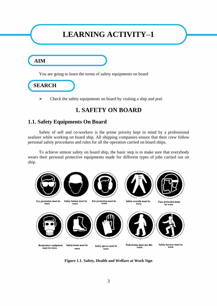
To achieve utmost safety on board ship, the basic step is to make sure that everybody
wears their personal protective equipments made for different types of jobs carried out on
ship.
Figure 1.1. Safety, Health and Welfare at Work Sign
LEARNING ACTIVITY–1
SEARCH
AIM
4
Personal protective equipments must always be chosen according to the hazard being
faced and the kind of work being undertaken, in accordance with the findings of the risk
assessment. It can be classified as follows:
1.1.1. Head protection
Safety helmets are most commonly provided as protection against falling objects.
They can also protect against crushing or a sideways blow and chemical splashes. The
hazards may vary and no one type of helmet is ideal as protection in every case. Design
details are normally decided by the manufacturer whose primary consideration will be
compliance with an appropriate standard. The standard selected should reflect the findings of
the risk assessment. Safety equipment should be used in accordance with manufacturers’
instructions.
Helmets
The shell of a helmet should be of one piece seamless construction designed to resist
impact. The harness or suspension when properly adjusted forms a cradle for supporting the
protector on the wearer’s head. The crown straps help absorb the force of impact. They are
designed to permit a clearance of approximately 25 mm between the shell and the skull of
the wearer. The harness or suspension should be properly adjusted before a helmet is worn.
Bump cap
A bump cap is simply an ordinary cap with a hard penetration-resistant shell. They are
useful as protection against bruising and abrasion when working in confi ned spaces such as
a main engine crankcase or a double bottom tank. They do not, however, afford the same
protection as safety helmets and are intended only to protect against minor knocks.
Hair
Personnel working on or near to moving machinery have always to be on their guard
against the possibility of their hair becoming entangled in the machinery. Long hair should
always be covered by a hair net or safety cap when working with or near moving machinery.
1.1.2. Hearing protection
All persons exposed to high levels of noise, eg in machinery spaces, should wear ear
protection of a type recommended as suitable for the particular circumstances. Protectors are
of three types – ear plugs, disposable or permanent, and ear muffs.
Ear plugs
WATCH YOUR HEAD!
5
The simplest form of ear protection is the ear plug. However, ear plugs have the
disadvantage of limited capability of noise level reduction. Ear plugs of rubber or plastic
have only limited effect, in that extremes of high or low frequency cause the plug to vibrate
in the ear canal causing a consequential loss in protection. Disposable ear plugs are
recommended because it may be diffi cult to keep re-usable ear plugs clean on a ship. Ear
plugs should never be used by anyone with ear trouble without medical advice.
Ear muffs
In general, ear muffs provide a more effective form of hearing protection. They
consist of a pair of rigid cups designed to completely envelope the ears, fi tted with soft
sealing rings to fi t closely against the head around the ears. The ear cups are connected by a
spring loaded headband (or neck band) that ensures that the sound seals around the ears are
maintained. Different types are available and provision should be made according to the
circumstances of use and expert advice.
1.1.3. Face and eye protection
The main causes of eye injury are:
Infra-red rays – gas welding
Ultra-violet rays – electric welding
Exposure to chemicals
Exposure to particles and foreign bodies.
A wide variety of protectors are available, designed to international standard specifi
cations, to protect against these different types of hazard. Ordinary prescription (corrective)
spectacles, unless manufactured to a safety standard, do not afford protection. Certain box-
type goggles are designed so that they can be worn over ordinary spectacles.
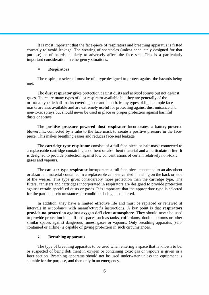
1.1.4. Respiratory protective equipment
Respiratory protective equipment is essential for protection when work has to be done
in conditions of irritating, dangerous or poisonous dust, fumes or gases.
There are two main types of equipment that perform different functions:
a respirator fi lters the air before it is inhaled
breathing apparatus supplies air or oxygen from an uncontaminated source.
Advice on the selection, use and maintenance of the equipment is contained in the
relevant standard. This should be available to all those concerned with the use of respiratory
protective equipment on board ship.
6
It is most important that the face-piece of respirators and breathing apparatus is fi tted
correctly to avoid leakage. The wearing of spectacles (unless adequately designed for that
purpose) or of beards is likely to adversely affect the face seat. This is a particularly
important consideration in emergency situations.
Respirators
The respirator selected must be of a type designed to protect against the hazards being
met.
The dust respirator gives protection against dusts and aerosol sprays but not against
gases. There are many types of dust respirator available but they are generally of the
ori-nasal type, ie half-masks covering nose and mouth. Many types of light, simple face
masks are also available and are extremely useful for protecting against dust nuisance and
non-toxic sprays but should never be used in place or proper protection against harmful
dusts or sprays.
The positive pressure powered dust respirator incorporates a battery-powered
blowerunit, connected by a tube to the face mask to create a positive pressure in the face-
piece. This makes breathing easier and reduces face-seal leakage.
The cartridge-type respirator consists of a full face-piece or half mask connected to
a replaceable cartridge containing absorbent or absorbent material and a particulate fi lter. It
is designed to provide protection against low concentrations of certain relatively non-toxic
gases and vapours.
The canister-type respirator incorporates a full face-piece connected to an absorbent
or absorbent material contained in a replaceable canister carried in a sling on the back or side
of the wearer. This type gives considerably more protection than the cartridge type. The
filters, canisters and cartridges incorporated in respirators are designed to provide protection
against certain specifi ed dusts or gases. It is important that the appropriate type is selected
for the particular circumstances or conditions being encountered.
In addition, they have a limited effective life and must be replaced or renewed at
intervals in accordance with manufacturer’s instructions. A key point is that respirators
provide no protection against oxygen defi cient atmosphere. They should never be used
to provide protection in confi ned spaces such as tanks, cofferdams, double bottoms or other
similar spaces against dangerous fumes, gases or vapours. Only breathing apparatus (self-
contained or airline) is capable of giving protection in such circumstances.
Breathing apparatus
The type of breathing apparatus to be used when entering a space that is known to be,
or suspected of being defi cient in oxygen or containing toxic gas or vapours is given in a
later section. Breathing apparatus should not be used underwater unless the equipment is
suitable for the purpose, and then only in an emergency.
7
Resuscitators
It is recommended that resuscitators of an appropriate kind should be provided when
any person may be required to enter a dangerous space.
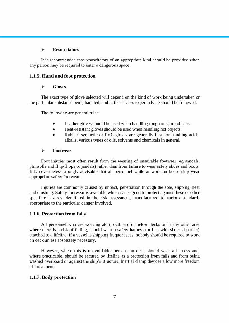
1.1.5. Hand and foot protection
Gloves
The exact type of glove selected will depend on the kind of work being undertaken or
the particular substance being handled, and in these cases expert advice should be followed.
The following are general rules:
Leather gloves should be used when handling rough or sharp objects
Heat-resistant gloves should be used when handling hot objects
Rubber, synthetic or PVC gloves are generally best for handling acids,
alkalis, various types of oils, solvents and chemicals in general.
Footwear
Foot injuries most often result from the wearing of unsuitable footwear, eg sandals,
plimsolls and fl ip-fl ops or jandals) rather than from failure to wear safety shoes and boots.
It is nevertheless strongly advisable that all personnel while at work on board ship wear
appropriate safety footwear.
Injuries are commonly caused by impact, penetration through the sole, slipping, heat
and crushing. Safety footwear is available which is designed to protect against these or other
specifi c hazards identifi ed in the risk assessment, manufactured to various standards
appropriate to the particular danger involved.
1.1.6. Protection from falls
All personnel who are working aloft, outboard or below decks or in any other area
where there is a risk of falling, should wear a safety harness (or belt with shock absorber)
attached to a lifeline. If a vessel is shipping frequent seas, nobody should be required to work
on deck unless absolutely necessary.
However, where this is unavoidable, persons on deck should wear a harness and,
where practicable, should be secured by lifeline as a protection from falls and from being
washed overboard or against the ship’s structure. Inertial clamp devices allow more freedom
of movement.
1.1.7. Body protection
8
Special outer clothing may be needed for protection when personnel are exposed to
particular contaminating or corrosive substances. This clothing should be kept for the
particular purpose and dealt with as directed in the relevant section of the Code.
High visibility clothing should be worn when it is important to be seen to be safe, eg during
loading and unloading operations.
1.1.8. Protection against drowning
Where work is being carried out over the side or in an exposed position where there is
a reasonable foreseeable risk of falling or being washed overboard, or where work is being
carried out in or from a ship’s boat, a lifebuoy with suffi cient line should be provided.
In addition and as appropriate, a lifejacket or buoyancy aid should be provided. Where
necessary, personnel should be provided with thermal protective clothing to reduce the risks
of cold shock.
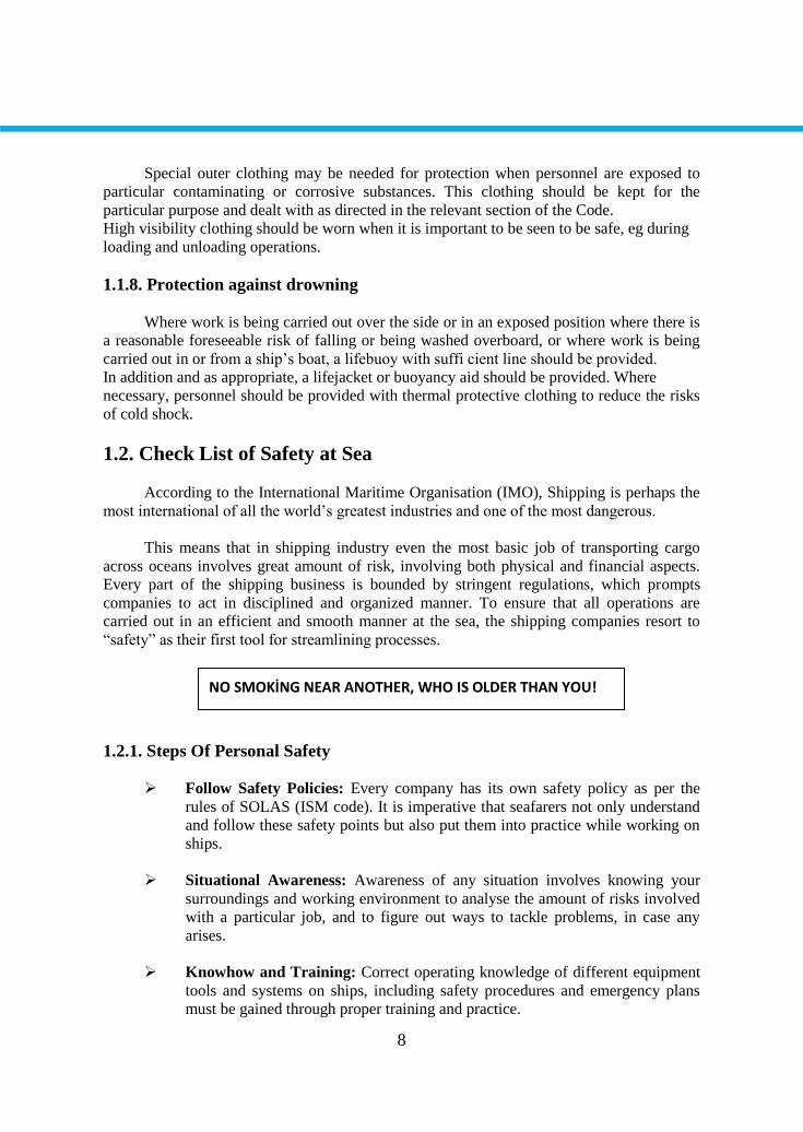
1.2. Check List of Safety at Sea
According to the International Maritime Organisation (IMO), Shipping is perhaps the
most international of all the world’s greatest industries and one of the most dangerous.
This means that in shipping industry even the most basic job of transporting cargo
across oceans involves great amount of risk, involving both physical and financial aspects.
Every part of the shipping business is bounded by stringent regulations, which prompts
companies to act in disciplined and organized manner. To ensure that all operations are
carried out in an efficient and smooth manner at the sea, the shipping companies resort to
“safety” as their first tool for streamlining processes.
1.2.1. Steps Of Personal Safety
Follow Safety Policies: Every company has its own safety policy as per the
rules of SOLAS (ISM code). It is imperative that seafarers not only understand
and follow these safety points but also put them into practice while working on
ships.
Situational Awareness: Awareness of any situation involves knowing your
surroundings and working environment to analyse the amount of risks involved
with a particular job, and to figure out ways to tackle problems, in case any
arises.
Knowhow and Training: Correct operating knowledge of different equipment
tools and systems on ships, including safety procedures and emergency plans
must be gained through proper training and practice.
NO SMOKİNG NEAR ANOTHER, WHO IS OLDER THAN YOU!
9
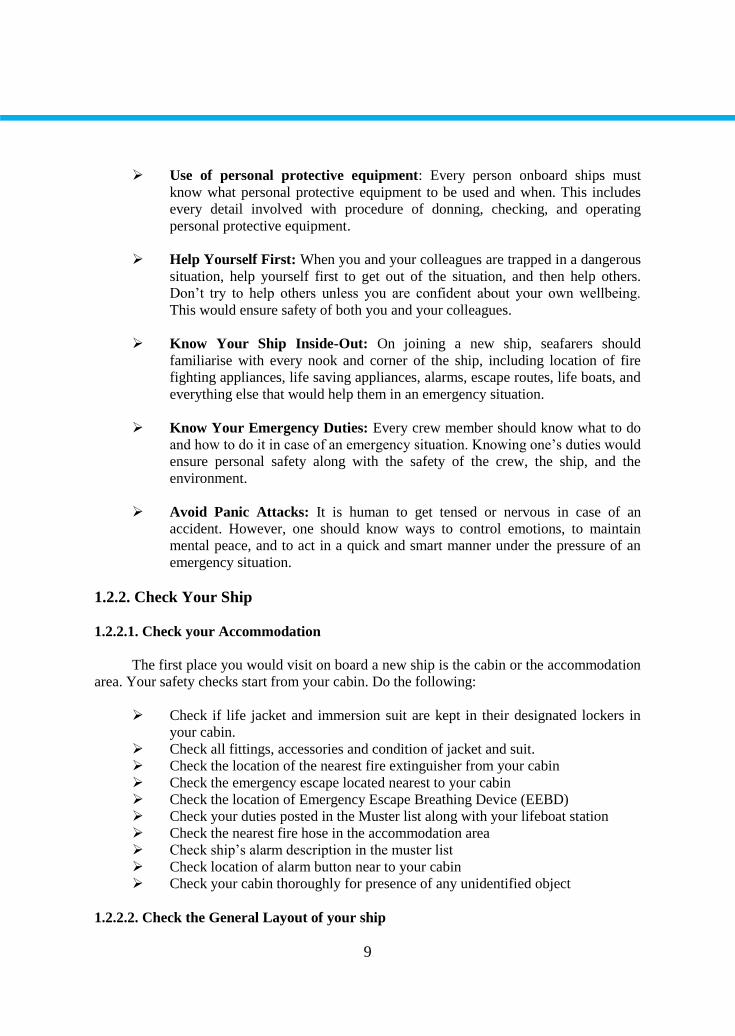
Use of personal protective equipment: Every person onboard ships must
know what personal protective equipment to be used and when. This includes
every detail involved with procedure of donning, checking, and operating
personal protective equipment.
Help Yourself First: When you and your colleagues are trapped in a dangerous
situation, help yourself first to get out of the situation, and then help others.
Don’t try to help others unless you are confident about your own wellbeing.
This would ensure safety of both you and your colleagues.
Know Your Ship Inside-Out: On joining a new ship, seafarers should
familiarise with every nook and corner of the ship, including location of fire
fighting appliances, life saving appliances, alarms, escape routes, life boats, and
everything else that would help them in an emergency situation.
Know Your Emergency Duties: Every crew member should know what to do
and how to do it in case of an emergency situation. Knowing one’s duties would
ensure personal safety along with the safety of the crew, the ship, and the
environment.
Avoid Panic Attacks: It is human to get tensed or nervous in case of an
accident. However, one should know ways to control emotions, to maintain
mental peace, and to act in a quick and smart manner under the pressure of an
emergency situation.
1.2.2. Check Your Ship
1.2.2.1. Check your Accommodation
The first place you would visit on board a new ship is the cabin or the accommodation
area. Your safety checks start from your cabin. Do the following:
Check if life jacket and immersion suit are kept in their designated lockers in
your cabin.
Check all fittings, accessories and condition of jacket and suit.
Check the location of the nearest fire extinguisher from your cabin
Check the emergency escape located nearest to your cabin
Check the location of Emergency Escape Breathing Device (EEBD)
Check your duties posted in the Muster list along with your lifeboat station
Check the nearest fire hose in the accommodation area
Check ship’s alarm description in the muster list
Check location of alarm button near to your cabin
Check your cabin thoroughly for presence of any unidentified object
1.2.2.2. Check the General Layout of your ship
10
When emergency strikes, time is one thing which is extremely precious. To save
maximum amount of time, every seafarer must know the complete layout of the ship, along
with the way to reach the muster station from any part of the ship. Familiarise yourself with
the general arrangement plan of your ship by visiting and exploring every accessible corner.
Do the following things:
Check the general layout of your accommodation from each deck
Check different ways to approach the muster station
Check forecastle of the ship and arrangements of escape routes provided
Check location of life raft and lifebuoy provided at the forecastle
Check aft part of the ship and arrangement of escape routes provided
Check location of lifebuoys in other parts of the ship
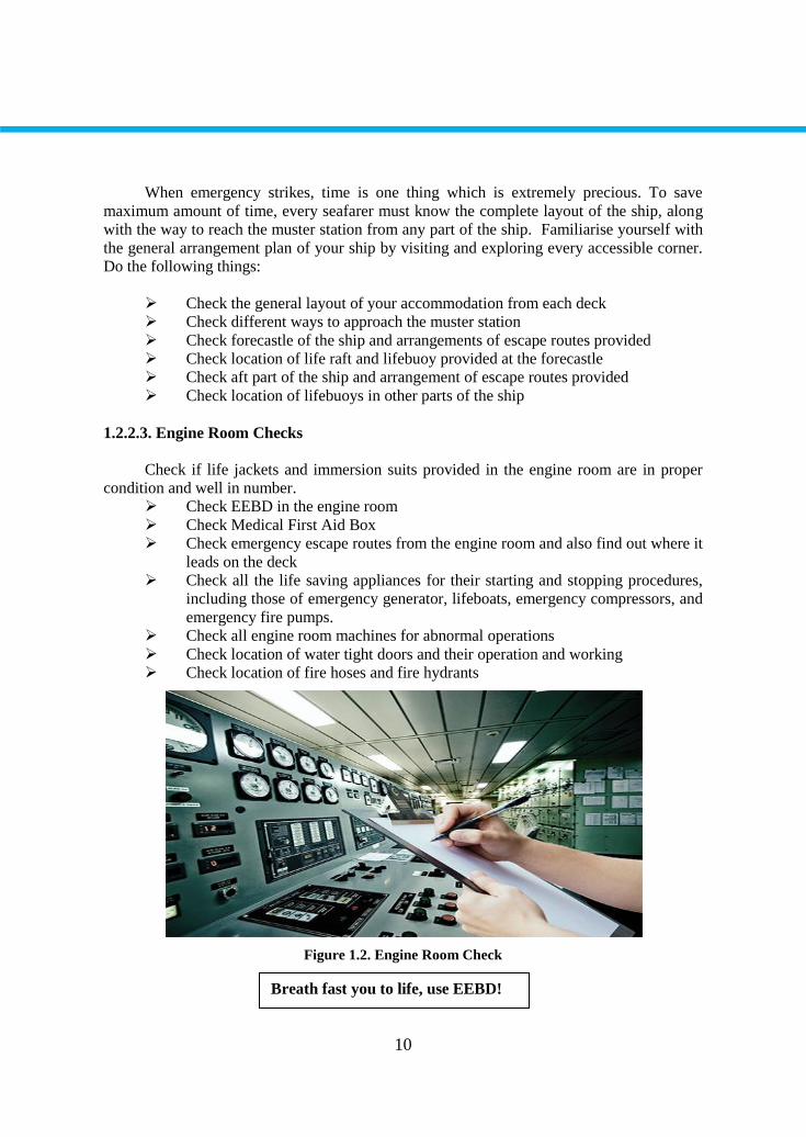
1.2.2.3. Engine Room Checks
Check if life jackets and immersion suits provided in the engine room are in proper
condition and well in number.
Check EEBD in the engine room
Check Medical First Aid Box
Check emergency escape routes from the engine room and also find out where it
leads on the deck
Check all the life saving appliances for their starting and stopping procedures,
including those of emergency generator, lifeboats, emergency compressors, and
emergency fire pumps.
Check all engine room machines for abnormal operations
Check location of water tight doors and their operation and working
Check location of fire hoses and fire hydrants
Figure 1.2. Engine Room Check
Breath fast you to life, use EEBD!

11
1.2.2.4. Deck Side Checks
Check gangway of the ship for proper lifting and lowering arrangement
Check net and railing in the gangway
Check all the railings and freeways on the deck
Check all life saving appliances provided on the deck
Check location of fire hoses and fire hydrants
Check location of fire plan
Check location of international shore coupling and connection
Check fire line on deck with main valves
Check the bunker station on deck for remote stopping of pumps.
1.2.2.5 Bridge Checks
Check location of lifejackets and immersion suits
Check EEBD location on bridge
Check location of lifebuoy
Check location of nearest fire extinguisher
Check location for storing EPIRB and SART
Check location of emergency fire pump switch
Check location of distress signal button on bridge
Check emergency escape route from bridge and ways to approach the muster
station
1.2.2.6. Galley Checks
Check location of the nearest fire extinguisher
Check location of fire blanket
Check location of fire alarm button
Check location of fire damper
Check location of nearest fire hose
Check location of nearest escape route and ways to approach muster station
from the galley
Check all electrical plugs and fitting for overheating or burning
Check all equipment for safe and accidental free operation
1.2.3. Check Lists And Forms
Every operation conducted on a ship is bounded by a checklist or a form (or both).
These tools ensure that no safety measure is overlooked while carrying out a job on ships.
Shipping companies are extremely cautious when it comes to these forms and checklists. It is
therefore imperative for every seafarer to learn about these important procedures to enhance
their own personal safety.
Technically, there are several of these checklists and forms on ships which are to be
referred and filled before carrying out different operations. Each of these procedures should

12
be thoroughly understood for averting any kind of trouble. To ensure that all necessary steps
are taken by seafarers for their personal safety, forms and checklists are filled and filed for
later reference. As soon as a seafarer boards a ship, following forms, checklists, and safety
manuals have to be signed.
1.2.3.1. Forms
Pre Familiarisation Form
Some companies advise their crew to complete a pre familiarisation form within 24 to
48hrs of joining the ship. When signed by the new seafarer, this form is a written proof that
an officer of the vessel has provided familiarization of different parts and safety systems of
the ship, including muster station, lifeboats, and life raft location.
Department Familiarisation Form
A separate familiarisation form has to be presented by the seafarer within 15 days of
joining a ship, in order to validate that he or she has completely understood the safety
equipment, procedures, and systems of the ship, including engine room, deck/bridge, and
galley. A senior officer is responsible to familiarise the newly joined seafarer with various
systems of the ship.
Marpol Declaration Form
Some companies are extra cautious when it comes to marine environment. To prevent
any kind of involvement in marine pollution activity, shipping companies ask seafarers to
sign a Marpol declaration form, which states that you are aware of all the pollution
regulations at sea and are liable to be suspended along with legal actions if any kind of
marine pollution results from your mistakes.
Personal Duty Form
A personal duty from is provided to the seafarer stating general duties onboard ship
according to the rank, duties to be performed during different emergency situations such as
oil spill, fire, grounding etc., and duties at the muster station and assigned lifeboat.
1.2.3.2. Checklists and Manuals
Personal Safety Checklist
A separate safety checklist is provided which states that all safety gears and personal
protective equipment (PPE) provided to you are in satisfactory working condition. This form
has to be read and signed.
Safety Manual
13
Ship is also provided with safety management system manuals containing all
procedures and operations that are to be carried out in the safest manner. These manuals are
also to be read and signed.
Fire Fighting Training Manual
Similar to safety manual, a fire fighting training manual, describing different
situations and methods to fight fire safely, is also provided. Operations of different fire
fighting appliances (FFA) are also described in this manual. This is to be read and signed.
14
APPLICATION ACTIVITY
Steps of Process Suggestions
Write the English names of the
equipments on board
Use the equipments at school
Do not waste the resources!
Prepare word cards You can play card games to memorize
the words
CHECKLIST
If you have behaviors listed below, evaluate yourself putting (X) in “Yes” box for
your earned skills within the scope of this activity otherwise put (X) in “No” box.
Evaluation Criteria Yes No
1. Have you learned the names of safety equipments on board?
2. Have you learned the areas of usage of safety equipments on
board?
3. Have you learned on which occasions to use the of safety
equipments on board?
4. Have you done an activity about the usage of of safety
equipments on board?
5. Have you tried safety equipments on board?
6. Have you learned the English equivalents of of safety equipments
on board?
EVALUATION
Please review your "No" answers in the form at the end of the evaluation. If you do
not find yourself enough, repeat learning activity. If you give all your answers "Yes" to all
questions, pass to the "Measuring and Evaluation".
APPLICATION ACTIVITY
15
MEASURING AND EVALUATION
Write TRUE or FALSE to the following statements.
1. ( ) Protective clothing is a coverall which protects the body of the crew member from
hazardous substance like hot oil, water, welding spark etc.
2. ( ) The most important part of the human body is the knee.
3. ( ) Some of the gloves provided are heat resistant gloves to work on hot surface.
4. ( ) Welding glass or goggles are used for eye protection, whereas Protective goggles
are used for welding operation which protects the eyes from high intensity spark.
5. ( ) Use of chemicals on board ship is very frequent and some chemicals are very
dangerous.
EVALUATION
Please compare your answers with the answer key.If you have wrong answers, you
need to review the Learning Activity. If you give right answers to all questions, pass to the
next learning activity.
MEASURING AND EVALUATION
16
LEARNING ACTIVITY–2
You are going to learn the terms of deck maintenance
Visit a vessel, shipyard
2. SHIP MAINTENANCE
2.1. Maintenance On Board
This unit covers the following topics.
The officer responsible for the overall maintenance of a ship.
The three different coating for protecting from corrosion.
The basic type of paint used on a ship.
The different stages in preparation of a piece of metal for painting.
The dock survey.
Much of the work of the deck department on board concerns the maintenance of the
ship and her fittings. This is the responsibility of the chief officer. He and the men in his
charge must protect the ship from the damaging effects of salt water, changes in temperature
and the action of waves.
The principle material used in building a ship is mild steel, and steel of different types
is used for making most fittings and equipment. Unfortunately, steel undergoes a chemical
change known as rusting when in contact with air, water or salt solutions. This causes the
metal to deteriorate rapidly, unless some form of protection is given.
To try and prevent from this corrosion, the metal is coated with cement wash,
bitumen and paint. Cement wash is a mixture of cement powder and fresh water. It is used
in fresh water tanks and double bottom tanks. Bitumen is used in bilges and peak tanks. It is
also used on metal decks before they are sheathed with wood. However, the principle
protective coating is paint. There are many types of paint available nowadays in a wide
variety of colours and it is no longer necessary for the boat swain to mix his own.
The most common kinds of paints found on board ship are as follows: metal primers,
which applied to a bare surface to give protection against rust and to act as a key to the next
coat - primers, which are used over the primer before the top coat - top coats, which provide
a hard-wearing surface and give the required colour - heat-resistant paints for radiators and
LEARNING ACTIVITY–2
SEARCH
AIM
17
pipes and for the ship’s funnel - non-slip paints for use on weather decks and other suitable
surface such as companion ways and varnishes to give a clear protective coat to wood work.
For painting, the surface of a ship’s hull is divided into three distinct areas: the top side,
boot-topping and bottom. Topside paint is supplied in the company’s colours or in light grey,
if the vessel is a warship. It is applied to the area of the ship’s hull which is out of the water
when the ship is loaded. A ship’s bottom is given coating of anti fouling paint. Anti fouling
paints contain toxicants which are poisonous to marine life. The toxicants have to dissolve
out of paint into the surrounding water in order to be effective.
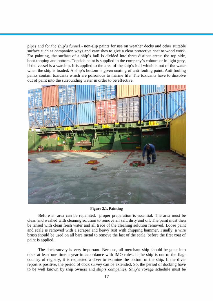
Figure 2.1. Painting
Before an area can be repainted, proper preparation is essential. The area must be
clean and washed with cleaning solution to remove all salt, dirty and oil. The paint must then
be rinsed with clean fresh water and all trace of the cleaning solution removed. Loose paint
and scale is removed with a scraper and heavy rust with chipping hammer. Finally, a wire
brush should be used on all bare metal to remove the last of the scale, before the first coat of
paint is applied.
The dock survey is very important. Because, all merchant ship should be gone into
dock at least one time a year in accordance with IMO rules. If the ship is out of the flag-
country of registry, it is requested a diver to examine the bottom of the ship. If the diver
report is positive, the period of dock survey can be extended. So, the period of docking have
to be well known by ship owners and ship’s companies. Ship’s voyage schedule must be
18
planned according to the dock survey. There are three kinds of docking. These are slipway,
dry dock and floating dock. The works during the dock survey are as follows;
The pitting and corrosion control of the sheet iron of the bottom and top sides.
To rust off the bottom or sand rusting, if necessary.
To change the sheet iron of the bottom and top sides, if necessary.
To paint the top sides, boot-topping and bottom.
The check on the zinc blocks on the bottom and rudder, and galvanic action.
The check on the propeller, rudder and steering gear system.
The check on shaft glands and brakets.
The maintenance of valves in connected with sea, and sea- chest valves.
The control and the maintenance of the fresh water, fuel oil& diesel oil tanks.
The control and the maintenance of the topsides and double bottom tanks.
The control and the maintenance of the ship’s anchor, shackles and windlass.
The most significant difficulties encountered.
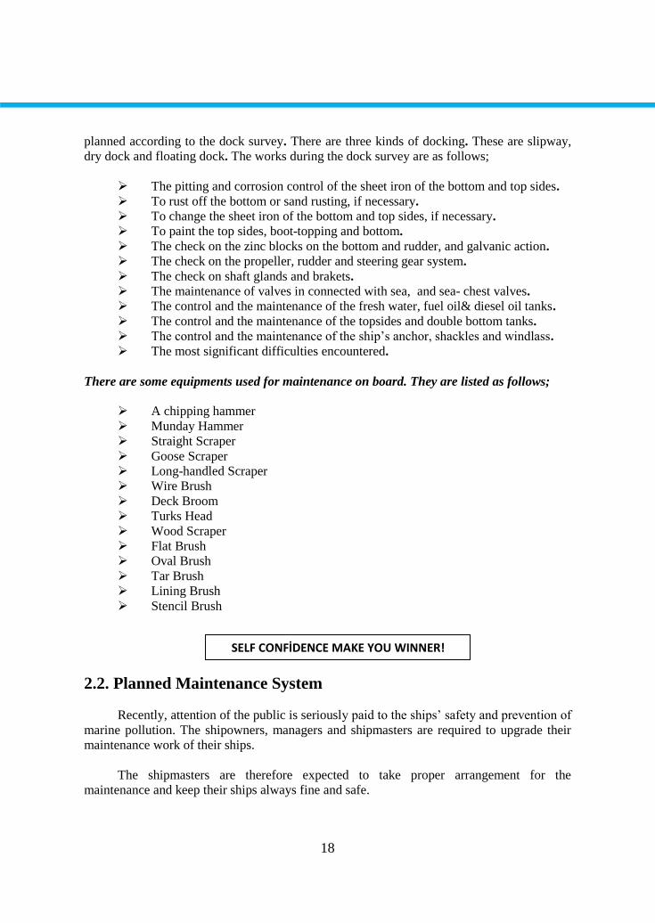
There are some equipments used for maintenance on board. They are listed as follows;
A chipping hammer
Munday Hammer
Straight Scraper
Goose Scraper
Long-handled Scraper
Wire Brush
Deck Broom
Turks Head
Wood Scraper
Flat Brush
Oval Brush
Tar Brush
Lining Brush
Stencil Brush
2.2. Planned Maintenance System
Recently, attention of the public is seriously paid to the ships’ safety and prevention of
marine pollution. The shipowners, managers and shipmasters are required to upgrade their
maintenance work of their ships.
The shipmasters are therefore expected to take proper arrangement for the
maintenance and keep their ships always fine and safe.
SELF CONFİDENCE MAKE YOU WINNER!
19
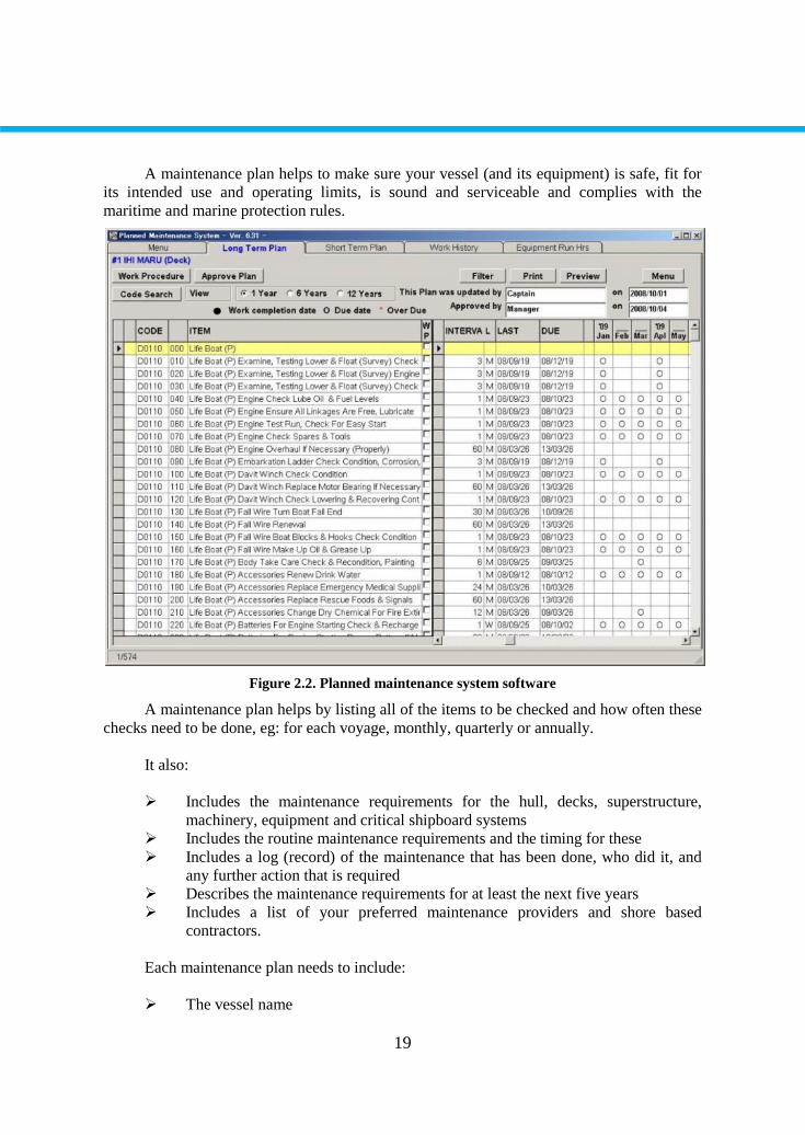
A maintenance plan helps to make sure your vessel (and its equipment) is safe, fit for
its intended use and operating limits, is sound and serviceable and complies with the
maritime and marine protection rules.
Figure 2.2. Planned maintenance system software
A maintenance plan helps by listing all of the items to be checked and how often these
checks need to be done, eg: for each voyage, monthly, quarterly or annually.
It also:
Includes the maintenance requirements for the hull, decks, superstructure,
machinery, equipment and critical shipboard systems
Includes the routine maintenance requirements and the timing for these
Includes a log (record) of the maintenance that has been done, who did it, and
any further action that is required
Describes the maintenance requirements for at least the next five years
Includes a list of your preferred maintenance providers and shore based
contractors.
Each maintenance plan needs to include:
The vessel name
20
The scheduled checks and maintenance to be carried out over at least the next
five years
A place to record the outcomes of maintenance checks
A place to record the maintenance that needs to be done or has been done
A place to record, sign and date any amendments made to the maintenance plan.
You need to do checks before, during and after each voyage. These checks will help
you to find out if any critical items need attention before the due date on your maintenance
plan. The checks you do will depend on your vessel and operation.
Pre-departure checks may include checking:
The general condition of the hull of the ship above the water level
Fuel and oil levels
Trip provisions
The charts and the weather
That all hatches are closed and your gear is stowed securely
The lifesaving, firefighting and radio equipment.
Post-trip check examples may include:
Making sure the log book is filled in and any new hazards are logged
Checking the vessel has been refueled
Making sure that any loose equipment has been made secure
Following-up after any voyage incidents. For example, checking if a repair is
needed where the hull scraped against rocks, or making sure a fire extinguisher
that leaked CO2 is serviced.
You must maintain a vessel according to its maintenance plan. This means doing the
checks and routine maintenance as scheduled, to ensure your ship and its equipment remains
fit for the intended use and operating limits.
There are checklist examples for on board maintenance below which will assist the
shipmaster in maintenance work as routine and before arrival at a port. These check lists are
helpful and useful for the shipmaster, his crew members as well as the the shipowners.
Item Check points Result Remarks
Ventilators The condition to be checked, e.g. corrison, wastage
Are closing appliances operating in satisfaction…
Air pipes The condition to be checked, e.g. corrison, wastage
Piping The condition to be checked, e.g. corrison, wastage
Campanion
ways
The condition to be checked, e.g. corrison, wastage
The watertightness of doors, packing, hinge handles
to be checked
Watertight The condition to be checked, e.g. corrison, wastage
21
Doors The watertightness including packing, cleats and
tarpaulins to be checked.
Cargo hatch
and other
hatches
The condition to be checked, e.g. corrison, wastage
The condition of coaming to be checked.
The condition of coaming stays to be checked.
The condition of coaming hatch covers to be checked.
The watertightness including packing, cleats and
tarpaulins to be checked
Rail The condition to be checked, e.g. corrison, wastage,
missing
Bulwark The condition including stays to be checked, e.g.
corrison, wastage and damage.
Item Check points Result Remarks
Cargo hold
The condition of frames, brakets, bulkhead, tank top
etc. to be checked, e.g. corrosion, wastage, crack,
damage.
Topside tanks The condition of frames, log., trans rings,bulhead etc.
to be checked e.g. corrosion, wastage, crack, damage.
Ballast tanks The condition of frames, log., trans rings,bulhead etc.
to be checked e.g. corrosion, wastage, crack, damage
Piping
arrangements
on deck
The condition to be checked e.g. corrosion, wastage,
leakage.
Electric cable
arrangements
on deck
The condition of cable pipes, cable arrangement to be
checked, e.g. corrosion, wastage, damage.
Engine room To be clean.
Main engines The operating condition to be checked.
Auxilary
machinery The operating condition to be checked.
Generators The operating condition to be checked.
Piping
arrangement
in engine
room
The operating condition to be checked, e.g. corrosion,
wastage, leakage.
Electric cable
arrangements
in engine
room
The condition to be checked.
Main switch
board
The operating condition to be checked and insulating
mats to be available on the floor in ftront of and at the
break of switchboard.
22
Cargo gear
appliances
The condition of posts, booms and winches including
loose gear tobe checked, e.g. corrosion, wastage,
damage.
Windlass and
mooring
winches
The operating condition to be checked. The condition
windlass and mooring winches including grading plate
at the control station to be checked, e.g. corrosion,
damage
2.3. Dry Dock
A dry dock is a narrow basin or vessel that can be flooded to allow a load to be floated
in, then drained to allow that load to come to rest on a dry platform. Dry docks are used for
the construction, maintenance, and repair of ships, boats, and other watercraft.
2.3.1. Types of dry dock
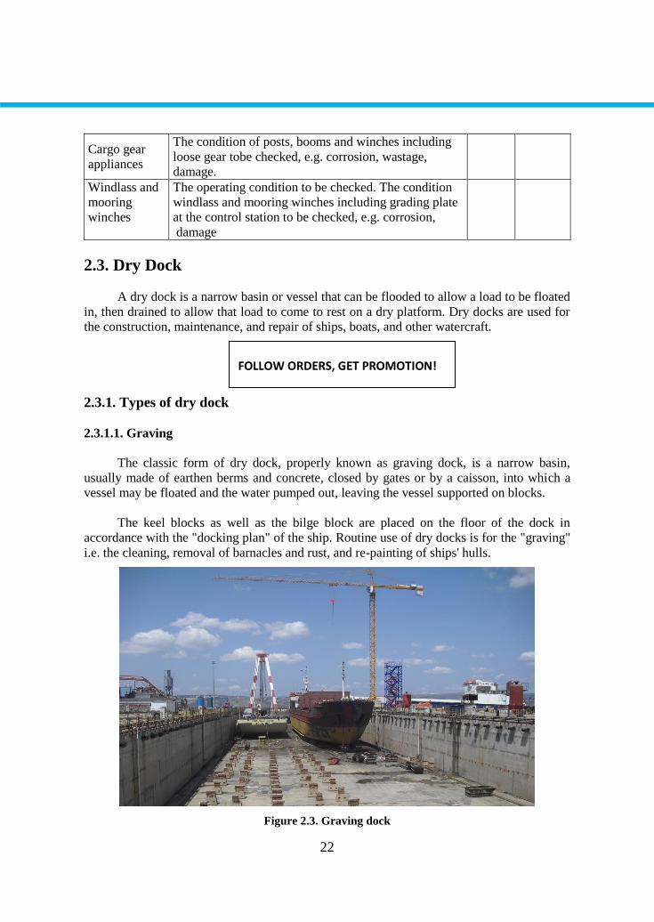
2.3.1.1. Graving
The classic form of dry dock, properly known as graving dock, is a narrow basin,
usually made of earthen berms and concrete, closed by gates or by a caisson, into which a
vessel may be floated and the water pumped out, leaving the vessel supported on blocks.
The keel blocks as well as the bilge block are placed on the floor of the dock in
accordance with the "docking plan" of the ship. Routine use of dry docks is for the "graving"
i.e. the cleaning, removal of barnacles and rust, and re-painting of ships' hulls.
Figure 2.3. Graving dock
FOLLOW ORDERS, GET PROMOTION!
23
Some fine-tuning of the ship's position can be done by divers while there is still some
water left to manoeuvre it about. It is extremely important that supporting blocks conform to
the structural members so that the ship is not damaged when its weight is supported by the
blocks. Some anti-submarine warfare warships have protruding sonar domes, requiring that
the hull of the ship be supported several metres from the bottom of the drydock.
Once the remainder of the water is pumped out, the ship can be freely inspected or
serviced. When work on the ship is finished, water is allowed to re-enter the dry dock and
the ship is carefully refloated.
Modern graving docks are box-shaped, to accommodate the newer, boxier ship
designs, whereas old dry docks are often shaped like the ships that are planned to be docked
there. This shaping was advantageous because such a dock was easier to build, it was easier
to side-support the ships, and less water had to be pumped away.
Dry docks used for building Navy vessels may occasionally be built with a roof. This
is done to prevent spy satellites from taking pictures of the dry dock and any ships or
submarines that may be in it. Today, covered dry docks are usually used only when servicing
or repairing a fleet ballistic missile submarine. Another advantage of covered dry docks is
that work can take place independently of the weather; this is frequently used by modern
shipyards for construction especially of complex, high-value vessels like cruise ships where
delays would incur a high cost.
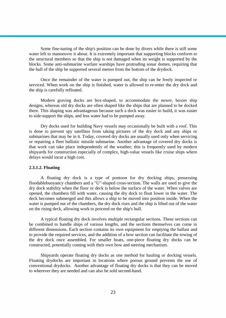
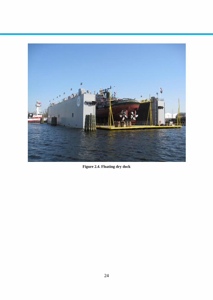
2.3.1.2. Floating
A floating dry dock is a type of pontoon for dry docking ships, possessing
floodablebuoyancy chambers and a "U"-shaped cross-section. The walls are used to give the
dry dock stability when the floor or deck is below the surface of the water. When valves are
opened, the chambers fill with water, causing the dry dock to float lower in the water. The
deck becomes submerged and this allows a ship to be moved into position inside. When the
water is pumped out of the chambers, the dry dock rises and the ship is lifted out of the water
on the rising deck, allowing work to proceed on the ship's hull.
A typical floating dry dock involves multiple rectangular sections. These sections can
be combined to handle ships of various lengths, and the sections themselves can come in
different dimensions. Each section contains its own equipment for emptying the ballast and
to provide the required services, and the addition of a bow section can facilitate the towing of
the dry dock once assembled. For smaller boats, one-piece floating dry docks can be
constructed, potentially coming with their own bow and steering mechanism.
Shipyards operate floating dry docks as one method for hauling or docking vessels.
Floating drydocks are important in locations where porous ground prevents the use of
conventional drydocks. Another advantage of floating dry docks is that they can be moved
to wherever they are needed and can also be sold second-hand.
24
Figure 2.4. Floating dry dock
25
APPLICATION ACTIVITY
Steps of Process Suggestions
You should do a research at the shipyard During your search take help your
teacher.
You can visit the ships at the port You should be in contact with the
Harbour Master
CHECKLIST
If you have behaviors listed below, evaluate yourself putting (X) in “Yes” box for
your earned skills within the scope of this activity otherwise put (X) in “No” box.
Evaluation Criteria Yes No
1. Can you remember the painting preparation application?
2. Have you learned the scrapping?
3. Have you learned the accomodation ladder?
4. Have you done an activity about the scrapping?
5. Hve you seen any windlass or nmooring wi
EVALUATION
Please review your "No" answers in the form at the end of the evaluation. If you do
not find yourself enough, repeat learning activity. If you give all your answers "Yes" to all
questions, pass to the "Measuring and Evaluation".
APPLICATION ACTIVITY
26
MEASURING AND EVALUATION
Write TRUE or FALSE to the following statements.
1. ( ) To try and prevent from this corrosion, the metal is coated with cement wash,
bitumen and paint
2. ( ) All merchant ship should be gone into dock at least one time a month in
accordance with IMO rules.
3. ( ) Hot Work is any work which involves a source of ignition or temperature
sufficiently high enough to cause ignition of a flammable gas mixture
4. ( ) Chief Officer is the one who retains the ultimate responsibility for the complete
working of the dry dock
EVALUATION
Please compare your answers with the answer key. If you have wrong answers, you
need to review the Learning Activity. If you give right answers to all questions, pass to the
next learning activity.
MEASURING AND EVALUATION
27
LEARNING ACTIVITY–3
You are going to learn the terms of nautical charts and publications
Find a nautical map
Search for the hydrographic offices on the net
Check the nauticalpublications
3. NAUTICAL CHARTS AND PUBLICATIONS
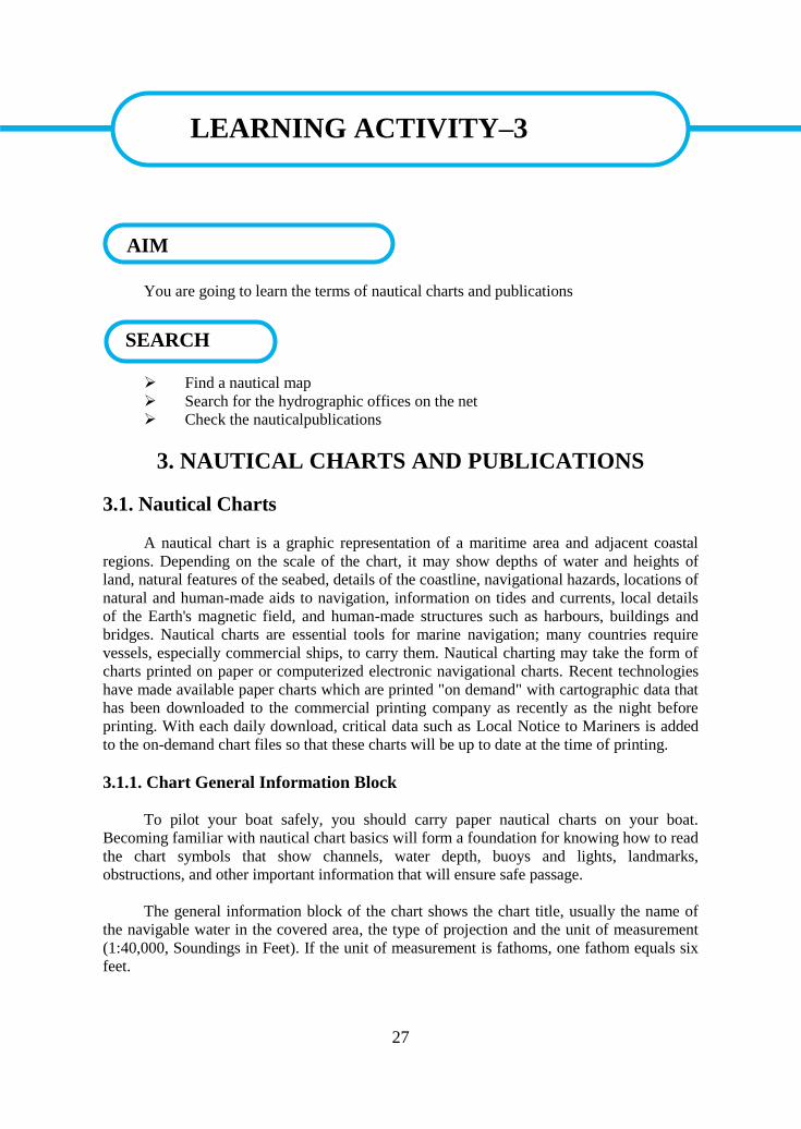
3.1. Nautical Charts
A nautical chart is a graphic representation of a maritime area and adjacent coastal
regions. Depending on the scale of the chart, it may show depths of water and heights of
land, natural features of the seabed, details of the coastline, navigational hazards, locations of
natural and human-made aids to navigation, information on tides and currents, local details
of the Earth's magnetic field, and human-made structures such as harbours, buildings and
bridges. Nautical charts are essential tools for marine navigation; many countries require
vessels, especially commercial ships, to carry them. Nautical charting may take the form of
charts printed on paper or computerized electronic navigational charts. Recent technologies
have made available paper charts which are printed "on demand" with cartographic data that
has been downloaded to the commercial printing company as recently as the night before
printing. With each daily download, critical data such as Local Notice to Mariners is added
to the on-demand chart files so that these charts will be up to date at the time of printing.
3.1.1. Chart General Information Block
To pilot your boat safely, you should carry paper nautical charts on your boat.
Becoming familiar with nautical chart basics will form a foundation for knowing how to read
the chart symbols that show channels, water depth, buoys and lights, landmarks,
obstructions, and other important information that will ensure safe passage.
The general information block of the chart shows the chart title, usually the name of
the navigable water in the covered area, the type of projection and the unit of measurement
(1:40,000, Soundings in Feet). If the unit of measurement is fathoms, one fathom equals six
feet.
LEARNING ACTIVITY–3
SEARCH
AIM
28
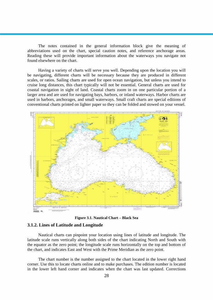
The notes contained in the general information block give the meaning of
abbreviations used on the chart, special caution notes, and reference anchorage areas.
Reading these will provide important information about the waterways you navigate not
found elsewhere on the chart.
Having a variety of charts will serve you well. Depending upon the location you will
be navigating, different charts will be necessary because they are produced in different
scales, or ratios. Sailing charts are used for open ocean navigation, but unless you intend to
cruise long distances, this chart typically will not be essential. General charts are used for
coastal navigation in sight of land. Coastal charts zoom in on one particular portion of a
larger area and are used for navigating bays, harbors, or inland waterways. Harbor charts are
used in harbors, anchorages, and small waterways. Small craft charts are special editions of
conventional charts printed on lighter paper so they can be folded and stowed on your vessel.
Figure 3.1. Nautical Chart – Black Sea
3.1.2. Lines of Latitude and Longitude
Nautical charts can pinpoint your location using lines of latitude and longitude. The
latitude scale runs vertically along both sides of the chart indicating North and South with
the equator as the zero point; the longitude scale runs horizontally on the top and bottom of
the chart, and indicates East and West with the Prime Meridian as the zero point.
The chart number is the number assigned to the chart located in the lower right hand
corner. Use this to locate charts online and to make purchases. The edition number is located
in the lower left hand corner and indicates when the chart was last updated. Corrections
29
published in the Notice to Mariners that occur after the publish date will need to be entered
by hand.
3.1.3. Soundings and Fathom Curves
One of the most important functions of a nautical chart is to show the depth and
bottom characteristics through numbers, color codes and underwater contour lines. The
numbers indicate soundings and show the depth in that area at low tide. Soundings in white
indicate deep water, which is why channels and open water are typically white. Shoal water,
or shallow water, is indicated by blue on the chart and should be approached with caution
using a depth finder. Fathom curves are the wavy lines, and they provide a profile of the
bottom.
3.1.4. Location of the Compass Rose
Nautical charts have one or more compass roses printed on them. A compass rose is
used to measure directions using true or magnetic bearing. True direction is printed around
the outside, while magnetic is printed around the inside. Variation is the difference between
true and magnetic north for the covered area. It is printed with annual change in the center of
the compass rose. The compass rose is used to plot a course when navigating using direction
bearings.
3.1.5. Location of the Distance Scales
The last section of the chart to note is the distance scale. This is a tool used to measure
distance of a specific course drawn on the chart in nautical miles, yards, or meters. The scale
is usually printed at the top and bottom of the chart. The latitude and longitude scale can also
be used to measure distance.
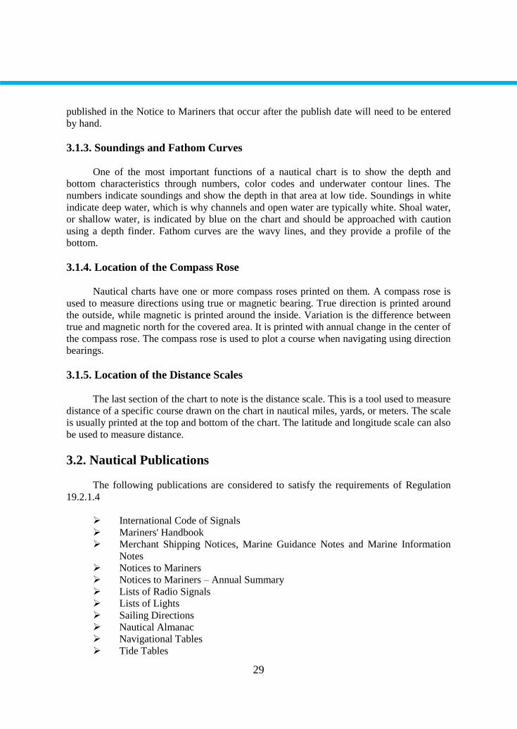
3.2. Nautical Publications
The following publications are considered to satisfy the requirements of Regulation
19.2.1.4
International Code of Signals
Mariners' Handbook
Merchant Shipping Notices, Marine Guidance Notes and Marine Information
Notes
Notices to Mariners
Notices to Mariners – Annual Summary
Lists of Radio Signals
Lists of Lights
Sailing Directions
Nautical Almanac
Navigational Tables
Tide Tables
30
Tidal Stream Atlases
Operating and Maintenance Instructions for Navigational Aids Carried by the
Ship
Figure 3.2. Nautical Publications
3.2.1. List of Lights and Fog Signals
This series of books provides extensive information on all lighthouses, lightships, lit
floating marks, fog signals and other lights of navigational significance. Each publication
also gives the characteristics of lights and fog signals, together with the equivalent foreign
language light descriptions. Tables can be used to calculate the geographical and luminous
ranges of lights. Details for all lights listed include the international number, location and/or
name, geographical co-ordinates, characteristics and intensity, elevation in metres, range in
sea miles and description of structure.
3.2.2. List of Radio Signals
The List of Radio Signals series provides comprehensive information on all aspects of
Maritime Radio Communications. The data is organised into six volumes, some divided into
several parts for ease of handling. Each of the six volumes is presented in a user-friendly
format with full colour photographs and diagrams.
The contents range from a complete listing of stations handling Maritime Public
Correspondence to a full range of products and services essential for compliance with the
GMDSS (Global Maritime Distress and Safety System). The volumes also feature radio
stations broadcasting weather services and forecasts and a detailed explanation of the
complexities of Global Satellite Position Fixing Systems.
NP281 (Parts 1 & 2) - Maritime Radio Stations
NP282 - Radio Aids to Navigation, Satellite Navigation Systems, Differential
GPS (DGPS) Legal Time, Radio Time Signals and Electronic Position Fixing
Systems
NP 283 (Parts 1 & 2) - Maritime Safety Information Services
NP 284 - Meteorological Observation Stations
NP 285 - Global Maritime Distress and Safety System (GMDSS)

31
NP 286 (Parts 1 - 8) - Pilot Services, Vessel Traffic Services and Port
Operations
3.2.3. Sailing Directions
Often referred to as Pilots, Sailing Directions are designed for use by the merchant
mariner on all classes of ocean-going vessels with essential information on all aspects of
navigation. Sailing Directions are complementary to Standard Nautical Charts and provide
worldwide coverage in 75 volumes. Each publication contains photography and views, as
well as information on navigational hazards, buoyage, meteorological data, details of
pilotage, regulations, port facilities and guides to major port entry.
3.2.4. Tide Tables
Tide Tables detail the times and heights of high and low waters for over 230 standard
and 6000 secondary ports in the UK and Ireland, Europe, the Indian Ocean, South China Sea
and Pacific Ocean for each day of the year. The tables outline methods of prediction, the
effect of meteorological conditions on tides and provide additional information on
exceptional tidal factors in each area.
3.2.5. Tidal Stream Atlases
Tidal Stream Atlases display, in diagrammatic form, the major tidal streams for
selected waters of north-western Europe, including direction and rate at hourly intervals.
Graded arrows illustrate Mean, Neap and Spring tidal rates in tenths of a knot. There is also a
diagram to help you calculate the tidal stream rate for a given date.
3.2.6. Manual of Tides
This is a largely mathematical, detailed description of tidal theory and its application
to the analysis and prediction of tides and tidal streams.
3.2.7. Tidal Handbooks
These outline the method of harmonic tidal analysis for long and short observation
periods and include information on datums for hydrographic surveys.
32
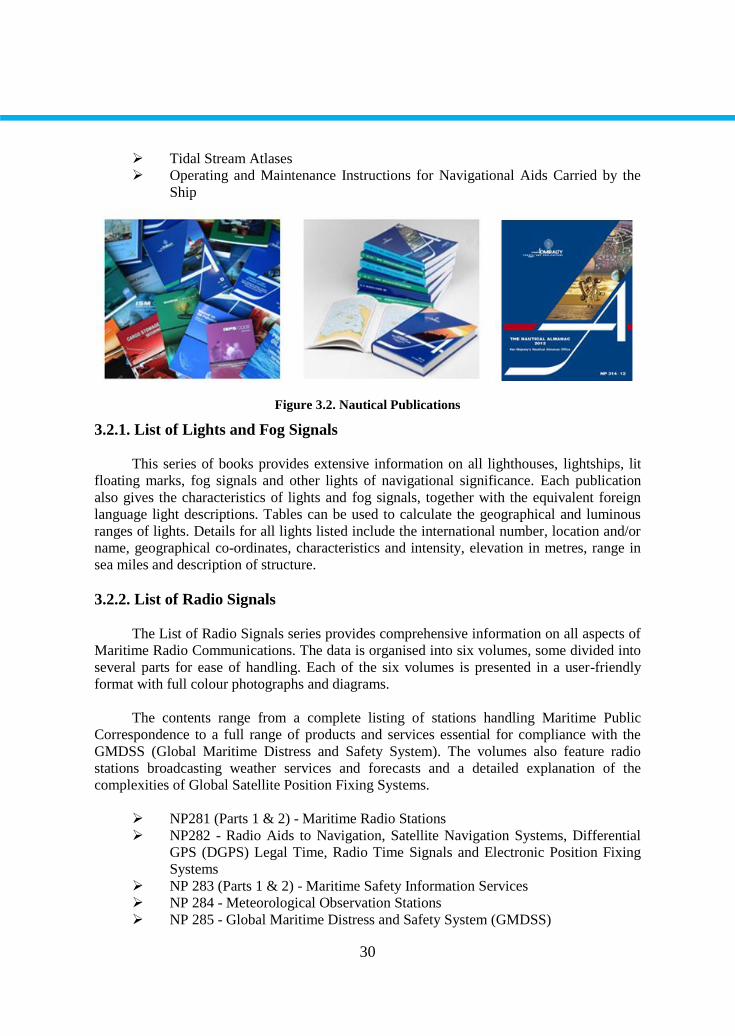
Figure 3.3. Tide Tables and Mariners Handbook
3.2.8. The Mariners Handbook (NP100)
A comprehensive guide to seamanship and key aspects of maritime navigation.
Content includes essential information on charts and their use, the communication of
navigational information, the maritime environment, restrictions to navigation and maritime
pollution and conservation.
3.2.9. Nautical Almanac
A nautical almanac is a publication describing the positions of a selection of celestial
bodies for the purpose of enabling navigators to use celestial navigation to determine the
position of their ship while at sea. The Almanac specifies for each whole hour of the year the
position on the Earth's surface (in declination and Greenwich hour angle) at which the sun,
moon, planets and first point of Aries is directly overhead. The positions of 57 selected stars
are specified relative to the first point of Aries.
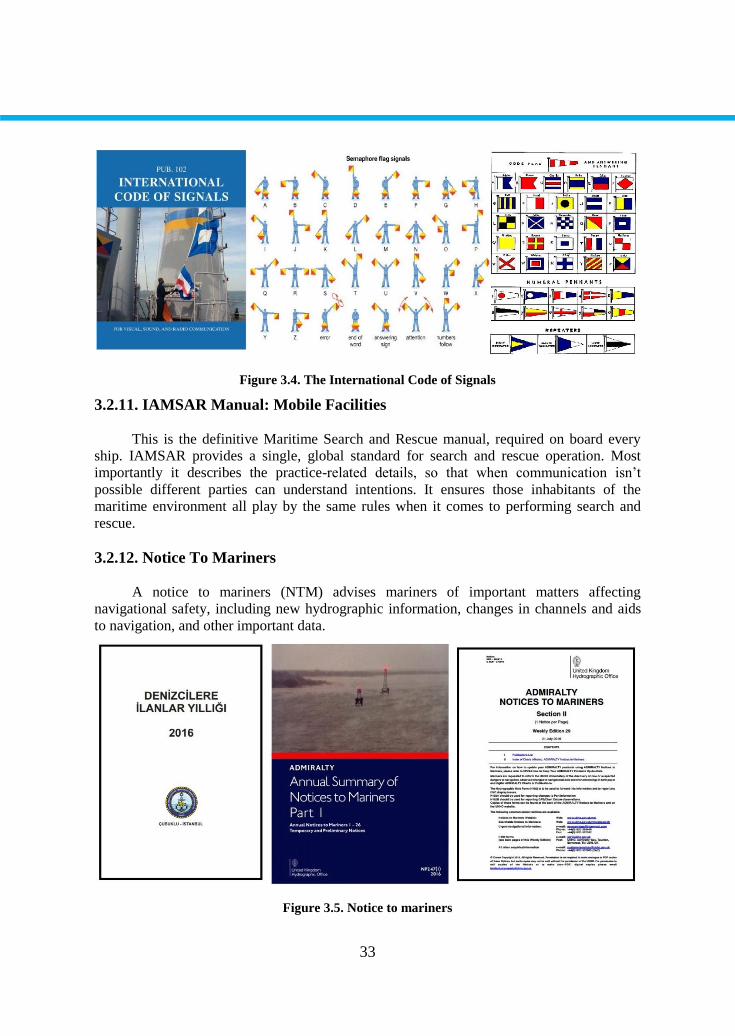
3.2.10. The International Code of Signals
The International Code of Signals (ICS) is an international system of signals and
codes for use by vessels to communicate important messages regarding safety of navigation
and related matters. Signals can be sent by flaghoist, signal lamp (blinker), flag semaphore,
radiotelegraphy, and radiotelephony. The International Code is the most recent evolution of a
wide variety of maritime flag signalling systems.
33
Figure 3.4. The International Code of Signals
3.2.11. IAMSAR Manual: Mobile Facilities
This is the definitive Maritime Search and Rescue manual, required on board every
ship. IAMSAR provides a single, global standard for search and rescue operation. Most
importantly it describes the practice-related details, so that when communication isn’t
possible different parties can understand intentions. It ensures those inhabitants of the
maritime environment all play by the same rules when it comes to performing search and
rescue.
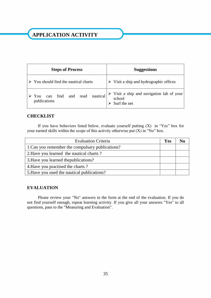
3.2.12. Notice To Mariners
A notice to mariners (NTM) advises mariners of important matters affecting
navigational safety, including new hydrographic information, changes in channels and aids
to navigation, and other important data.
Figure 3.5. Notice to mariners

34
3.2.13. The annual summary of notices to mariners
The annual summary of notices to mariners, also popularly known by its publication
number NP 247 (1) and (2), is a publication issued by hydrographic office on yearly basis.
The notices advice mariners on important matters related to ship’s navigation, hydro graphic
information, aids to navigation, and changes in shipping channels.
35
APPLICATION ACTIVITY
Steps of Process Suggestions
You should find the nautical charts Visit a ship and hydrographic offices
You can find and read nautical
publications
Visit a ship and navigation lab of your
school
Surf the net
CHECKLIST
If you have behaviors listed below, evaluate yourself putting (X) in “Yes” box for
your earned skills within the scope of this activity otherwise put (X) in “No” box.
Evaluation Criteria Yes No
1.Can you remember the compulsary publications?
2.Have you learned the nautical charts ?
3.Have you learned thepublications?
4.Have you practised the charts ?
5.Have you used the nautical publications?
EVALUATION
Please review your "No" answers in the form at the end of the evaluation. If you do
not find yourself enough, repeat learning activity. If you give all your answers "Yes" to all
questions, pass to the "Measuring and Evaluation".
APPLICATION ACTIVITY
36
MEASURING AND EVALUATION
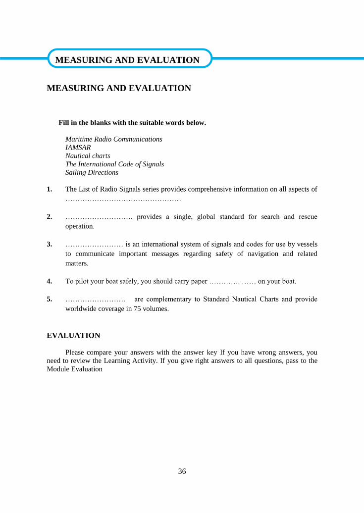
Fill in the blanks with the suitable words below.
Maritime Radio Communications
IAMSAR
Nautical charts
The International Code of Signals
Sailing Directions
1. The List of Radio Signals series provides comprehensive information on all aspects of
…………………………………………
2. ………………………. provides a single, global standard for search and rescue
operation.
3. …………………… is an international system of signals and codes for use by vessels
to communicate important messages regarding safety of navigation and related
matters.
4. To pilot your boat safely, you should carry paper …………. …… on your boat.
5. ……………………. are complementary to Standard Nautical Charts and provide
worldwide coverage in 75 volumes.
EVALUATION
Please compare your answers with the answer key If you have wrong answers, you
need to review the Learning Activity. If you give right answers to all questions, pass to the
Module Evaluation
MEASURING AND EVALUATION
37
LEARNING ACTIVITY–4
You are going to learn about the definition of meteorology, meteorological terms,
abbreviations of meteorological terms, weather symbols and abbrevations, radiofacsimile
symbols and contractions
Visit a Meteorology Office
4. METEOROLOGY
4.1. General Meteorology
4.1.1. Meteorology
Meteorology is the science of observing and predicting the weather. Climate is defined
as statistical weather information that describes the variation of weather at a given place for a
specified interval. Weather is the day-to-day state of the atmosphere, and its short-term
variation. Weather is the combination of temperature, humidity, precipitation, cloudiness,
visibility, and wind.
4.1.1.1. Atmosphere
The atmosphere is the shell of air and water vapour surrounding the earth. The layers
of the atmosphere are; troposphere, stratosphere, mesosphere, and thermosphere. Almost all
of the earth's weather occurs in the troposphere.
4.1.1.2. Temperature
Temperature is a measure of heat energy in degrees. Several different temperature
scales are in use. On the Fahrenheit (F) scale, pure water freezes at 32° and boils at 212°. On
the Celsius (C) scale, the freezing point is 0° and the boiling point is 100°. On the Kelvin (K) scale, the freezing point is 273° and the boiling point is 373°.
4.1.1.3. Pressure
Atmospheric pressure is one of the basic elements of a meteorologicalobservation. It is
a measure of the force exerted by air on all objects. Air pressure is related to temperature.
SEARCH
AIM
LEARNING ACTIVITY–4

38
Warm air is lighter than cold air and consequently exerts less pressure. Changes in air
pressure often signify weather changes. Rising air pressure usualy means fair weather,
whereas falling air pressure generally signals stormy weather.
4.1.1.4. Wind
Wind is the movement of air parallel to the Earth's surface. This motion is produced
by differences of atmospheric pressure. Winds blow from areas of high pressure toward
areas of low pressure. The factors that affect wind speed and direction are The Coriolis
Effect, centrifugal force and friction. Buys Ballot's Law describes the relationship of the
horizontal wind direction to the pressure distribution. In the Northern Hemisphere, if one
stands with his back to the wind, the pressure on his left is lower than the pressure on his
right. It is reversed in the Southern Hemisphere. Geostrophic wind is a steady horizontal
motion of air along straight parallel isobars in an unchanging pressure. Gradient wind is a
steady horizontal air motion along curved parallel isobars in an unchanging pressure. Local
winds result from thermal differences that generate a local pressure gradient.
4.1.1.5. Humidity
Humidity is a measure of the amount of water vapour in the air. Relative humidity is
the ratio of the pressure of water vapour present in the atmosphere to the saturation vapour
pressure at the same temperature. The relative humidity will vary with the air temperature.
As air temperature decreases, the relative humidity increases or as the air warms, the relative
humidity drops. At some point, saturation takes place and any further cooling results in
condensation of some of the moisture. The temperature at which this occurs is called the dew
point.
4.1.1.6. Precipitation
All the forms of water that fall from the air to the Earth's surface are called
precipitation. If the air is above freezing, the precipitation will most likely be rain. If the air
is below freezing, the precipitation will most likely be snow. When air temperature is only a few degrees above freezing, precipitation may fall assleet.
4.1.1.7. Fog
The visible aggregate of tiny water droplets suspended in the atmosphere near the
earth's surface is called fog. A light or thin fog is usually called a mist. Fog may occur when
the moisture content of the air is increased beyond the saturation point. Fogs formed as a
result of radiation cooling are termed radiation fogs. Advection fogs form when warm humid
air from different sources passes over a much colder surface causing condensation. Steam
fog is a type of advection fog. It occurs when cool air blows over a warm surface. Frontal
fog occurs in the cold air mass of a front.
4.1.1.8. Clouds
39
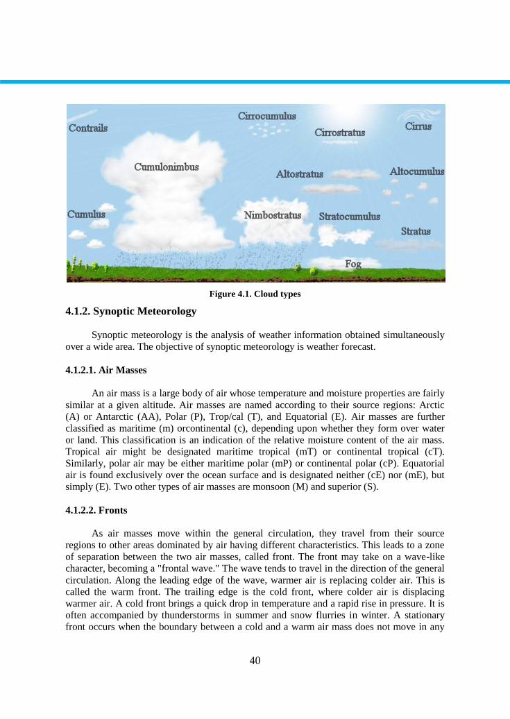
A cloud is a visible aggregate of tiny water droplets or ice crystals suspended in the
atmosphere. Clouds can be grouped into three according to either their appearance as cirrus,
cumulus or stratus or their height as follows.
High Clouds ( above 20000 feet)
Cirrus (Ci) is generally white, thin, silky cloud that has a tendency to
elongate.
Cirrocumulus (Cc) is small cotton-ball type cloud.
Cirrostratus (Cs) is thin, whitish, transparent, layerlike cloud.
Middle Clouds (between 6,500 and 20,000 feet)
Altocumulus (Ac) is gray, fluffy, and ball-like masses that tend to merge
together.
Altostratus (As) is like cirrostratus, but gray, thicker, and at a lower altitude.
Low Clouds (lower than 6,500 feet)
Stratocumulus (Sc) is low cloud appearing as soft, gray, roll-shaped
masses.
Stratus (St) is in a uniform layer resembling fog. Stratus is often quite
thick, permitting so little sunlight to penetrate.
Nimbostratus (Ns) is a low, dark, shapeless cloud layer, usually nearly
uniform and a typical rain cloud. The precipitation which falls from this
cloud is steady or intermittent, but not showery.
Cumulus (Cu) is dense cloud with vertical development formed by rising
air which is cooled as it reaches greater heights.
Cumulonimbus (Cb) is a massive cloud with great vertical development
associated with thunderstorms. Cumulonimbus often produces showers of
rain, snow, or hail, accompanied by lightning and thunder.
WHATEVER THE OUTSIDE WIND, YOUR AIR SHOULD BE PERFECT!
40
Figure 4.1. Cloud types
4.1.2. Synoptic Meteorology
Synoptic meteorology is the analysis of weather information obtained simultaneously
over a wide area. The objective of synoptic meteorology is weather forecast.
4.1.2.1. Air Masses
An air mass is a large body of air whose temperature and moisture properties are fairly
similar at a given altitude. Air masses are named according to their source regions: Arctic
(A) or Antarctic (AA), Polar (P), Trop/cal (T), and Equatorial (E). Air masses are further
classified as maritime (m) orcontinental (c), depending upon whether they form over water
or land. This classification is an indication of the relative moisture content of the air mass.
Tropical air might be designated maritime tropical (mT) or continental tropical (cT).
Similarly, polar air may be either maritime polar (mP) or continental polar (cP). Equatorial
air is found exclusively over the ocean surface and is designated neither (cE) nor (mE), but
simply (E). Two other types of air masses are monsoon (M) and superior (S).
4.1.2.2. Fronts
As air masses move within the general circulation, they travel from their source
regions to other areas dominated by air having different characteristics. This leads to a zone
of separation between the two air masses, called front. The front may take on a wave-like
character, becoming a "frontal wave." The wave tends to travel in the direction of the general
circulation. Along the leading edge of the wave, warmer air is replacing colder air. This is
called the warm front. The trailing edge is the cold front, where colder air is displacing
warmer air. A cold front brings a quick drop in temperature and a rapid rise in pressure. It is
often accompanied by thunderstorms in summer and snow flurries in winter. A stationary
front occurs when the boundary between a cold and a warm air mass does not move in any
41
direction. Anoccluded front results when a cold front overtakes a warm front on the ground,
lifting the warm air entirely aloft.
4.1.2.3. Cyclone and Anticyclone
The air pressure is measured in millibars (mb) or millimeter-mercury (mmHg).
Normal sea level pressure value is 1013 mbor760 mmHg. If the pressure value is over 1013
mb, it is called high-pressure, and if under 1013 mb, it is called low-pressure. Cyclone is the
name for low-pressure centers and antycyclone is for high-pressure centers. A cyclone is a
weather pattern consisting of a region of low air pressure some 1000 kilometres to 2000
kilometres in diameter around which air circulatescounterclockwise in the Northern
Hemisphere. An anticyclone is a weather pattern consisting of a broad region of high air
pressure around which air circulates clockwise in the Northern Hemisphere. In an
anticyclone, air descends near the center of the high, and the weather tends to be fair.
4.1.3. Weather Instruments
Weather conditions such as air temperature, pressure, humidity, precipitation are
measured by a variety of instruments.
4.1.3.1. Thermometers
Temperature is measured by a thermometer which is a glass tube in whichmercury
expands and contracts with the rise and fall of the temperature of the surrounding air.
Continuous temperatures are recorded by a thermograph consisting of a heat-sensitive metal
coil that moves a pen against a rotating drum.
4.1.3.2. Barometers
A cubic foot of air at standard sea-level temperature and pressure weighs 1.22 ounces.
Because of this weight, the atmosphere exerts a pressure upon the surface of the earth of
about 15 pounds per square inch. Atmospheric pressure is measuredeither by ananeroid
barometer or by a mercury barometer. The type of barometer used aboard ship is the aneroid
barometer. Continuous pressure is recorded by a barograph which is a recording barometer.
4.1.3.3. Anemometer
A wind vane indicates the direction of wind. An anemometer measures the force or
speed of the wind. Aboard ship the two instruments usually are mounted together. They
automatically transmit wind force and direction to indicators. Direction ismeasured in
degrees from the bow of the ship and speed is measured in knots.
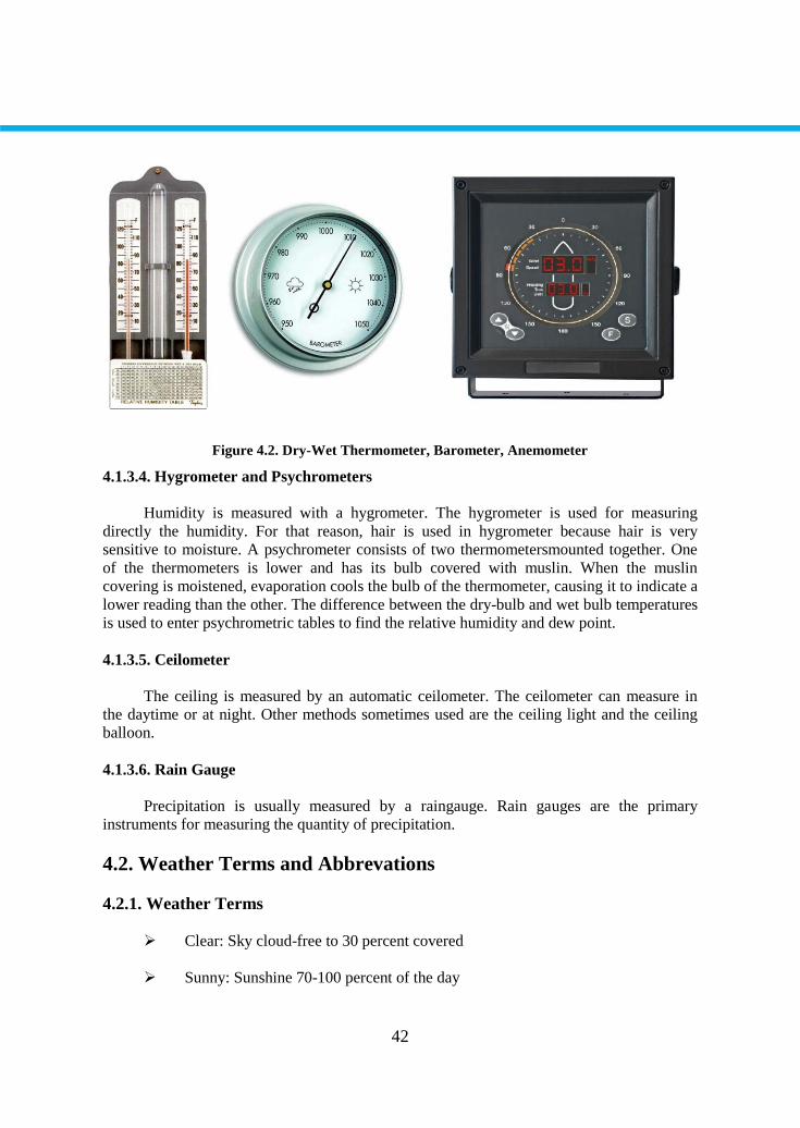
42
Figure 4.2. Dry-Wet Thermometer, Barometer, Anemometer
4.1.3.4. Hygrometer and Psychrometers
Humidity is measured with a hygrometer. The hygrometer is used for measuring
directly the humidity. For that reason, hair is used in hygrometer because hair is very
sensitive to moisture. A psychrometer consists of two thermometersmounted together. One
of the thermometers is lower and has its bulb covered with muslin. When the muslin
covering is moistened, evaporation cools the bulb of the thermometer, causing it to indicate a
lower reading than the other. The difference between the dry-bulb and wet bulb temperatures
is used to enter psychrometric tables to find the relative humidity and dew point.
4.1.3.5. Ceilometer
The ceiling is measured by an automatic ceilometer. The ceilometer can measure in
the daytime or at night. Other methods sometimes used are the ceiling light and the ceiling
balloon.
4.1.3.6. Rain Gauge
Precipitation is usually measured by a raingauge. Rain gauges are the primary
instruments for measuring the quantity of precipitation.
4.2. Weather Terms and Abbrevations
4.2.1. Weather Terms
Clear: Sky cloud-free to 30 percent covered
Sunny: Sunshine 70-100 percent of the day
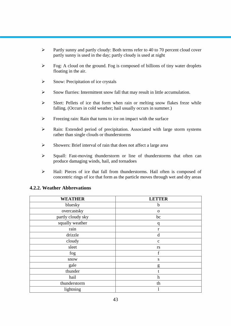
43
Partly sunny and partly cloudy: Both terms refer to 40 to 70 percent cloud cover
partly sunny is used in the day; partly cloudy is used at night
Fog: A cloud on the ground. Fog is composed of billions of tiny water droplets
floating in the air.
Snow: Precipitation of ice crystals
Snow flurries: Intermittent snow fall that may result in little accumulation.
Sleet: Pellets of ice that form when rain or melting snow flakes freze while
falling. (Occurs in cold weather; hail usually occurs in summer.)
Freezing rain: Rain that turns to ice on impact with the surface
Rain: Extended period of precipitation. Associated with large storm systems
rather than single clouds or thunderstorms
Showers: Brief interval of rain that does not affect a large area
Squall: Fast-moving thunderstorm or line of thunderstorms that often can
produce damaging winds, hail, and tornadoes
Hail: Pieces of ice that fall from thunderstorms. Hail often is composed of
concentric rings of ice that form as the particle moves through wet and dry areas
4.2.2. Weather Abbrevations
WEATHER LETTER
bluesky b
overcastsky o
partly cloudy sky bc
squally weather q
rain r
drizzle d
cloudy c
sleet rs
fog f
snow s
gale g
thunder t
hail h
thunderstorm th
lightning l
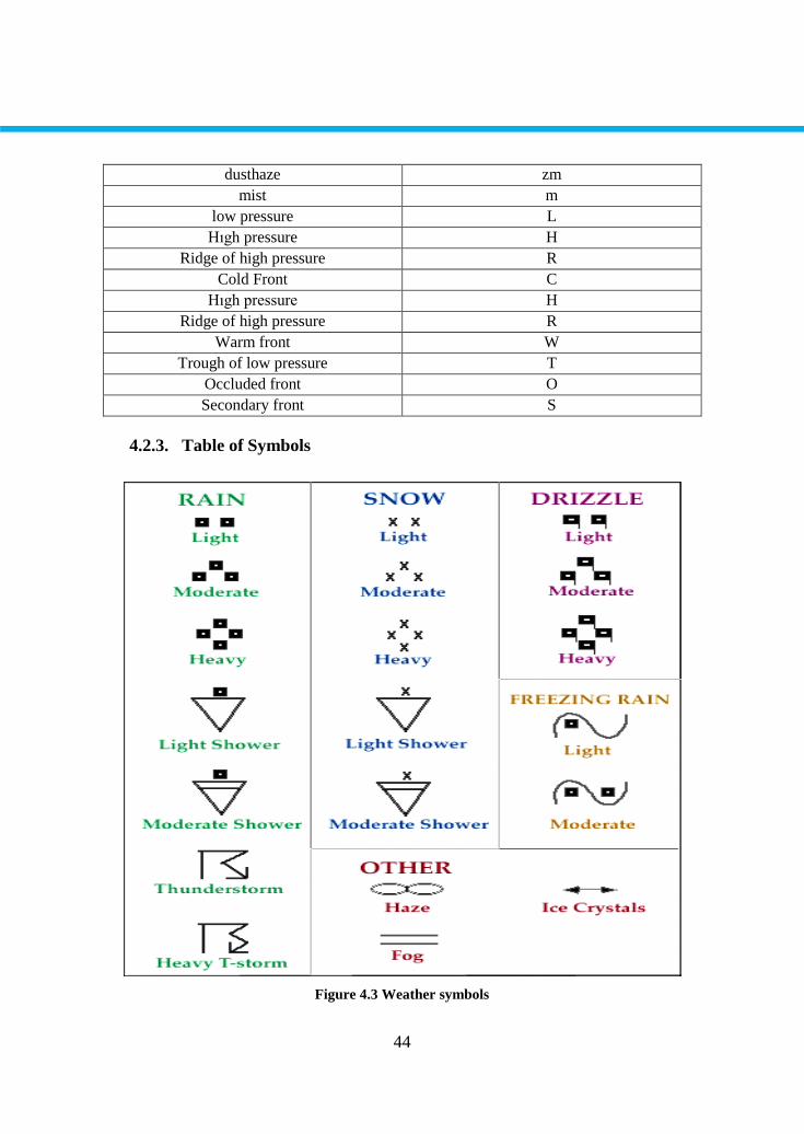
44
dusthaze zm
mist m
low pressure L
Hıgh pressure H
Ridge of high pressure R
Cold Front C
Hıgh pressure H
Ridge of high pressure R
Warm front W
Trough of low pressure T
Occluded front O
Secondary front S
4.2.3. Table of Symbols
Figure 4.3 Weather symbols
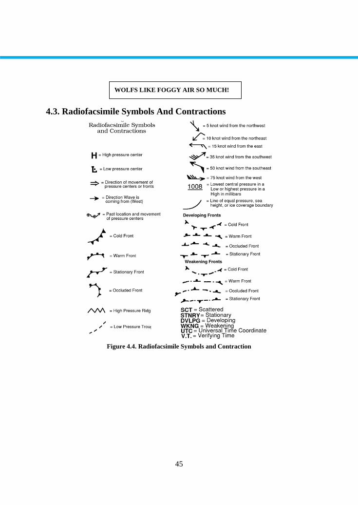
45
4.3. Radiofacsimile Symbols And Contractions
Figure 4.4. Radiofacsimile Symbols and Contraction
WOLFS LIKE FOGGY AIR SO MUCH!
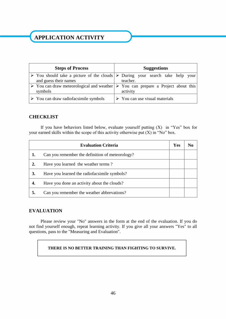
46
APPLICATION ACTIVITY
Steps of Process Suggestions
You should take a picture of the clouds
and guess their names
During your search take help your
teacher.
You can draw meteorological and weather
symbols
You can prepare a Project about this
activity
You can draw radiofacsimile symbols You can use visual materials
CHECKLIST
If you have behaviors listed below, evaluate yourself putting (X) in “Yes” box for
your earned skills within the scope of this activity otherwise put (X) in “No” box.
Evaluation Criteria Yes No
1. Can you remember the definition of meteorology?
2. Have you learned the weather terms ?
3. Have you learned the radiofacsimile symbols?
4. Have you done an activity about the clouds?
5. Can you remember the weather abbrevations?
EVALUATION
Please review your "No" answers in the form at the end of the evaluation. If you do
not find yourself enough, repeat learning activity. If you give all your answers "Yes" to all
questions, pass to the "Measuring and Evaluation".
APPLICATION ACTIVITY
THERE IS NO BETTER TRAINING THAN FIGHTING TO SURVIVE.
47
MEASURING AND EVALUATION
Match the following statements with the sentences
A the shell of air and water vapour surrounding the earth.
B a measure of heat energy in degrees.
C a visible aggregate of tiny water droplets or ice crystals
suspended in the atmosphere
D the movement of air parallel to the Earth's surface.
E a measure of the amount of water vapour in the air.
F one of the basic elements of a meteorological observation
EVALUATION
Please compare your answers with the answer keyIf you have wrong answers, you
need to review the Learning Activity. If you give right answers to all questions, pass to the
next learning activity.
1 Temperature
2 Atmosphere
3 Atmospheric
pressure
4 Wind
5 Humidity
6 A cloud
1 2 3 4 5 6
MEASURING AND EVALUATION
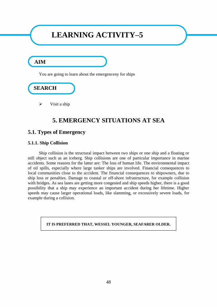
48
LEARNING ACTIVITY–5
You are going to learn about the emergenceny for ships
Visit a ship
5. EMERGENCY SITUATIONS AT SEA
5.1. Types of Emergency
5.1.1. Ship Collision
Ship collision is the structural impact between two ships or one ship and a floating or
still object such as an iceberg. Ship collisions are one of particular importance in marine
accidents. Some reasons for the latter are: The loss of human life. The environmental impact
of oil spills, especially where large tanker ships are involved. Financial consequences to
local communities close to the accident. The financial consequences to shipowners, due to
ship loss or penalties. Damage to coastal or off-shore infrastructure, for example collision
with bridges. As sea lanes are getting more congested and ship speeds higher, there is a good
possibility that a ship may experience an important accident during her lifetime. Higher
speeds may cause larger operational loads, like slamming, or excessively severe loads, for
example during a collision.
LEARNING ACTIVITY–5
SEARCH
AIM
IT IS PREFERRED THAT, WESSEL YOUNGER, SEAFARER OLDER.
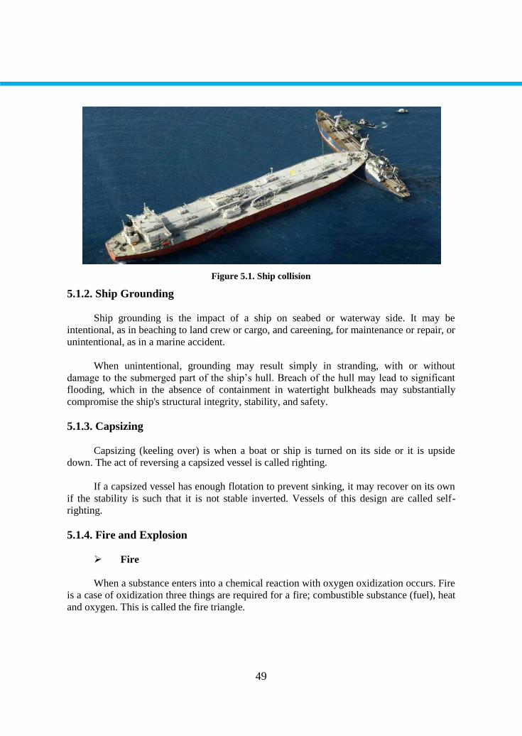
49
Figure 5.1. Ship collision
5.1.2. Ship Grounding
Ship grounding is the impact of a ship on seabed or waterway side. It may be
intentional, as in beaching to land crew or cargo, and careening, for maintenance or repair, or
unintentional, as in a marine accident.
When unintentional, grounding may result simply in stranding, with or without
damage to the submerged part of the ship’s hull. Breach of the hull may lead to significant
flooding, which in the absence of containment in watertight bulkheads may substantially
compromise the ship's structural integrity, stability, and safety.
5.1.3. Capsizing
Capsizing (keeling over) is when a boat or ship is turned on its side or it is upside
down. The act of reversing a capsized vessel is called righting.
If a capsized vessel has enough flotation to prevent sinking, it may recover on its own
if the stability is such that it is not stable inverted. Vessels of this design are called self-
righting.
5.1.4. Fire and Explosion
Fire
When a substance enters into a chemical reaction with oxygen oxidization occurs. Fire
is a case of oxidization three things are required for a fire; combustible substance (fuel), heat
and oxygen. This is called the fire triangle.
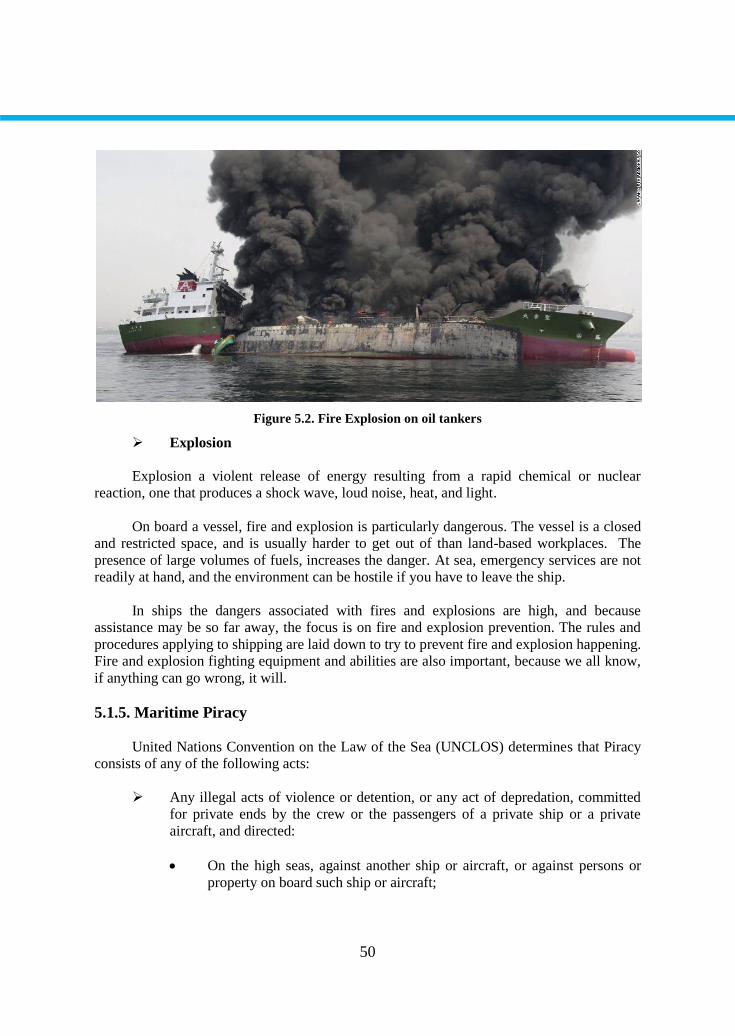
50
Figure 5.2. Fire Explosion on oil tankers
Explosion
Explosion a violent release of energy resulting from a rapid chemical or nuclear
reaction, one that produces a shock wave, loud noise, heat, and light.
On board a vessel, fire and explosion is particularly dangerous. The vessel is a closed
and restricted space, and is usually harder to get out of than land-based workplaces. The
presence of large volumes of fuels, increases the danger. At sea, emergency services are not
readily at hand, and the environment can be hostile if you have to leave the ship.
In ships the dangers associated with fires and explosions are high, and because
assistance may be so far away, the focus is on fire and explosion prevention. The rules and
procedures applying to shipping are laid down to try to prevent fire and explosion happening.
Fire and explosion fighting equipment and abilities are also important, because we all know,
if anything can go wrong, it will.
5.1.5. Maritime Piracy
United Nations Convention on the Law of the Sea (UNCLOS) determines that Piracy
consists of any of the following acts:
Any illegal acts of violence or detention, or any act of depredation, committed
for private ends by the crew or the passengers of a private ship or a private
aircraft, and directed:
On the high seas, against another ship or aircraft, or against persons or
property on board such ship or aircraft;
51
Against a ship, aircraft, persons or property in a place outside the
jurisdiction of any state;
Any act of voluntary participation in the operation of a ship or of an aircraft
with knowledge of facts making it a pirate ship or aircraft;
Any act of inciting or of intentionally facilitating an act described in
subparagraph (a) or (b).
5.1.6. Man Overboard
Man overboard is a situation in which a person has fallen from a boat or ship into the
water and is in need of rescue. Whoever sees the person's fall should shout "man overboard"
to alert other crew members and attempt to maintain visual contact with the person in the
water. Pointing continuously at the victim can aid the helmsman in approaching the victim.
5.2. Accident Prevention Precautions
5.2.1. Personal Protective Equipment
Personal protective equipment complying with the relevant Standard specific ations or
their equivalent must be worn by the operator and by those assisting with the operation to
protect them from particles of hot metal and slag, and their eyes and skin from ultraviolet
and heat radiation.
The operator should normally wear:
Welding shields or welding goggles with appropriate shade of filter. Goggles
are only recommended for gas welding and flame cutting
Leather gauntlets
Leather apron in appropriate circumstances
Long-sleeved natural fibre boiler suit or other approved protective clothing.
Clothing should be free of grease and oil and other flammable substances.
5.2.2. Pre-Use Equipment Check
Welding and flame-cutting equipment should be inspected by a competent person
before it is used to ensure that it is in a serviceable condition. In cold weather moisture
trapped in the equipment may freeze and, for example, cause valves to malfunction. It is
recommended that equipment be thawed out with hot water and cloths, never with naked
flames.
52
5.2.3. Precautions against fire and explosion
Before welding, flame-cutting or other hot work is begun, a check should be made that
there are no combustible solids, liquids or gases, at, below or adjacent to the area or work,
which might be ignited by heat or sparks from the work.
Such work should never be undertaken on surfaces covered with grease, oil or other
flammable or combustible materials. Where necessary, combustible materials and dunnage
should be moved to a safe distance before commencing operations. Such places should also
be free of materials that could release/ flammable substance for example if disturbed. When
welding is to be done in the vicinity of open hatches, suitable screens should be erected to
prevent sparks dropping down hatchways or hold ventilators. Port holes and other openings
through which sparks may fall should be closed where practicable. Where work is being
done close to or at bulkheads, decks or deckheads, the far side of the divisions should be
checked for materials and substances which may ignite, and for cables, pipelines or other
services which may be affected by the heat.
Cargo tanks, fuel tanks, cargo holds, pipelines, pumps and other spaces that have
contained flammable substances should be certificed as being free of flammable gases before
any repair work is commenced.
The testing should include, as appropriate, the testing of adjacent spaces, double
bottoms and cofferdams. Further tests should be carried out at regular intervals and before
hot work is recommenced following any suspension of the work. When preparing tankers
and similar ships all tanks, cargo pumps and pipelines should be thoroughly cleaned and
particular care taken with the draining and cleaning of pipelines that cannot be directly
flushed using the ship pumps.
Welding and flame-cutting operations should be properly supervised and kept under
regular observation. Suitable fire extinguishers should be kept at hand ready for use during
the operation. A person with a suitable extinguisher should also be stationed to keep watch
on areas not visible to the welder that may be affected. In view of the risk of delayed fires
resulting from the use of burning or welding apparatus, frequent checks should be made for
at least two hours after the work has stopped.
5.2.4. Electric Welding Equipment
In order to minimise personal harm from electric shock, electric welding power
sources for shipboard use should have a direct current (DC) output not exceeding 70V, with
a minimum ripple. Further information on DC power sources is given later in this chapter.
When DC equipment is not available, then AC output power sources may be used providing
they have an integral voltage limiting device to ensure that the idling voltage (the voltage
between electrode and work piece before an arc is struck between them) does not exceed
25V rms.
53
The proper function of the device (which may be affected by dust or humidity) should
be checked each time a welding set is used. Some voltage limiting devices are affected by
their angle of tilt from the vertical, so it is important that they are mounted and used in the
position specifi ed by the manufacturers. This requirement can be affected by adverse sea
conditions.
A “go-and-return” system using two cables from the welding set should be adopted
the welding return cable should be fi rmly clamped to the workpiece. Earthing of the
workpiece is used to provide protection against internal insulation failure of the welding
transformer, by keeping the workpiece at or near earth potential until the protective device
operates to cut off the main supply.
Where the welding circuit is not adequately insulated from the earthed referenced
mains supply, the workpiece should be earthed. The “return” cable of the welding set and
each workpiece should be separately earthed to the ship’s structure. The use of a single cable
with hull return is not recommended. The workpiece earthing conductor should be robust
enough to withstand possible mechanical damage and should be connected to the workpiece
and a suitable earth terminal by bolted lugs or secure screw clamps.
If an alternative method of protecting against welding transformer insulation failure is
used, the hazards caused by stray welding currents can be avoided by not earthing the
workpiece or the welding output circuit. It should be noted, that other equipment connected
to the workpiece may require earthing for safe operation
The lead and return cables should be of the minimum length practicable for the job
and of an appropriate cross-section to avoid voltage drop in transmission Cables should be
inspected before use; if the insulation is impaired or conductively reduced, they should not
be used. Cable connectors should be fully insulated when connected, and so designed and
installed that current carrying parts are adequately recessed when disconnected. Electrode
holders should be fully insulated so that no live part of the holder is exposed to touch, and,
where practicable, should be fitted with guards to prevent accidental contact with live
electrodes and as protection from sparks and splashes of weld metal.
A local switching arrangement or other suitable means should be provided for rapidly
cutting off current from the electrode should the operator get into difficulties and also for
isolating the holder when electrodes are changed. The direct current output from power
sources should not exceed 70V open circuit. The ripple on the output from the power source
should not exceed the values of the table below. The ripple magnitudes are expressed as
percentages of the DC, and the ripple peak is that with the same polarity as the DC.
Should it be necessary to use a power source with a DC output having a ripple
magnitude in excess of those stated in the table. For example a single phase rectifi er power
source, then a voltage limiting device should be incorporated in the power source to ensure
that the idling voltage does not exceed 42V.
54
5.2.5. Precautions To Be Taken During Electric Arc Welding
In addition to the protective clothing specified the welding operator should wear
nonconducting safety footwear. Clothing should be kept as dry as possible as some
protection against electric shock it is particularly important that gloves should be dry as wet
leather is a good conductor.
An assistant should be in continuous attendance during welding operations. The
assistant should be alert to the risk of accidental shock to the welder, and ready to cut off
power instantly, raise the alarm and provide artificial respiration without delay. It may be
desirable to have a second assistant if the work is to be carried out in difficult conditions.
Where persons other than the operator are likely to be exposed to harmful radiation or sparks
from electric arc welding, they should be protected by screens or other effective means.
In restricted spaces, where the operator may be in close contact with the ship’s
structure or is likely to make contact in the course of ordinary movements, protection should
be provided by dry insulating mats or boards.
There are increased risks of electric shock to the operator if welding is done in hot or
humid conditions because body sweat and damp clothing greatly reduce body resistance.
Under such conditions, the operation should be deferred until such time that an adequate
level of safety can be achieved. Under no circumstances should welders work while standing
in water or with any part of their body immersed.
The electrode holder should be isolated from the current supply before a used
electrode is removed and before a new electrode is inserted. This precaution is necessary
because some electrode coatings have extremely low resistance. Even a flux coating that is
normally insulating can become damp from sweating hands and thus potentially dangerous.
When the welding operation is completed or temporarily suspended, the electrode should be
removed from the holder. Hot electrode ends should be ejected into a suitable container; they
should not be handled with bare hands. Spare electrodes should be kept dry in their container
until required for use.
5.2.6. Compressed Gas Cylinders
Compressed gas cylinders should always be handled with care, whether full or empty.
They should be properly secured and stored in a location appropriate to their intended use
and risks which inadvertent release of gas may present.
The cylinders should be so secured as to be capable of quick and easy release, for
example, in the case of fi re. If available, cylinder trolleys should be used to transport
cylinders from one place to another. The protective caps over the valve should be screwed in
place when the cylinders are not in use or are being moved. Valves should be closed when
the cylinder is empty.
55
Where two or more cylinders of either oxygen or a fuel gas are carried the oxygen and
the fuel gas should be stowed in separate, well-ventilated compartments that are not subject
to extremes of temperature.
The space in which acetylene or other fuel gas cylinders are stowed should have no
electrical fittings or other sources of ignition and prominent and permanent “NO
SMOKING” signs should be displayed in the entrance and within the space. Empty cylinders
should be segregated from the full ones and so marked.
The following special precautions need to be taken in the case of cylinders of oxygen
and acetylene or other fuel gases:
Cylinders valves, controls and associated fi ttings should be kept free from oil,
grease and paint; controls should not be operated with oily hands
Gas should not be taken from such cylinders unless the correct pressure
reducing regulator has been attached to the cylinder outlet valve
Cylinders found to have leaks that cannot be stopped by closing the outlet valve
should be taken to the open deck away from any sources of heat or ignition and
slowly discharged to the atmosphere.
5.2.7. Gas Welding And Cutting
While this section deals almost exclusively with oxygen and acetylene, other fuel
gases may be used and similar precautions should be taken. The pressure of oxygen used for
welding should always be high enough to prevent acetylene flowing back into the oxygen
line.
Acetylene should not be used for welding at a pressure exceeding 1 atmosphere gauge
as it is liable to explode, even in the absence of air, when under excessive pressure. Non-
return valves should be fi tted adjacent to the torch in the oxygen and acetylene supply lines.
Flame arrestors should be provided in the oxygen and acetylene supply lines and will
usually be fi tted at the low pressure side of regulators although they may be duplicated at
the torch. Should a back fire occur the recommended fi rst action is to close the oxygen valve
on the blowpipe to prevent internal burning followed immediately by shutting off the fuel
gas at the blowpipe valve.
If there is a fl ashback into the hose and equipment, or a hose fire or explosion, or a
fire at the regulator connections or gas supply outlet points, the first action should be to
isolate the oxygen and fuel gas supplies at the cylinder valves or gas supply outlet points but
only if this can be done safely. Further action should follow in accordance with the vessel’s
fire drill requirements.
56
A watch should be kept on acetylene cylinders to ensure they are not becoming hot. If
they are, this could be a sign of acetylene decomposition and there is increased risk of
explosion. The cylinder stop valve should be closed immediately, which may limit or reduce
the decomposition but is unlikely to stop it.
Emergency action, such as evacuating the area and prolonged cooling by immersion or
with copious amounts of water will still be required. Consideration should be given to
jettisoning the cylinder overboard although movement of the cylinder can promote rapid
decomposition, and cooling should continue while it is being moved. Any acetylene cylinder
suspected of overheating should be approached with extreme caution because an impact
could set off an internal ignition which might cause an explosion only acetylene cylinders of
approximately equal pressures should be coupled.
In fixed installations, manifolds should be clearly marked with the gas they contain.
Manifold hose connections including inlet and outlet connections should be such that the
hose cannot be interchanged between fuel gases and oxygen manifolds and headers. Only
those hoses specially designed for welding and cutting operations should be used to connect
any oxy-acetylene blowpipe to gas outlets. Any length of hose in which a fl ashback has
occurred should be discarded.
The connections between hose and blowpipe and between hoses should be securely
fixed. Hoses should be arranged so that they are not likely to become kinked or tangled or be
tripped over, cut or otherwise damaged by moving objects or falling metal slag, sparks etc; a
sudden jerk or pull on the hose is liable to pull the blowpipe out of the operator’s hands or
cause a cylinder to fall or a hose connection to fail. Hoses in passageways should be covered
to avoid them becoming a tripping hazard.
Soapy water should be used for testing leaks in hoses. If there are leaks that cannot
easily be stopped, the gas supply should be isolated and the leaking components taken out of
service, replaced or repaired. If the leak is at a cylinder valve or pressure regulator
connection, the cylinder should be removed to a safe place in the open air. If it is a fuel-gas
cylinder, it should be taken well clear of any source of ignition.
Excessive force should never be used on cylinder valve spindles or hexagon nuts of
regulator connections in an attempt to stop a leak. Neither are sealing tape nor other jointing
materials recommended for use in an attempt to prevent leaks between metal-metal surfaces
that are designed to be gas tight. With an oxygen cylinder this could result in initiation of a
metal-oxygen fire. Blowpipes should be lit with a special friction igniter, stationary pilot fl
ame or other safe means. Should a blowpipe-tip opening become clogged, it should be
cleaned only with the tools especially designed for that purpose. When a blowpipe is to be
changed the gases should be shut off at the pressure-reducing regulators. To prevent a build-
up of dangerous concentrations of gas or fumes during a temporary stoppage or after
completion of the work, supply valves on gas cylinders and gas mains should be securely
closed and blowpipes, hoses and moveable pipes should be removed to lockers that open on
to the open deck. Oxygen should never be used to ventilate, cool or blow dust off clothing.
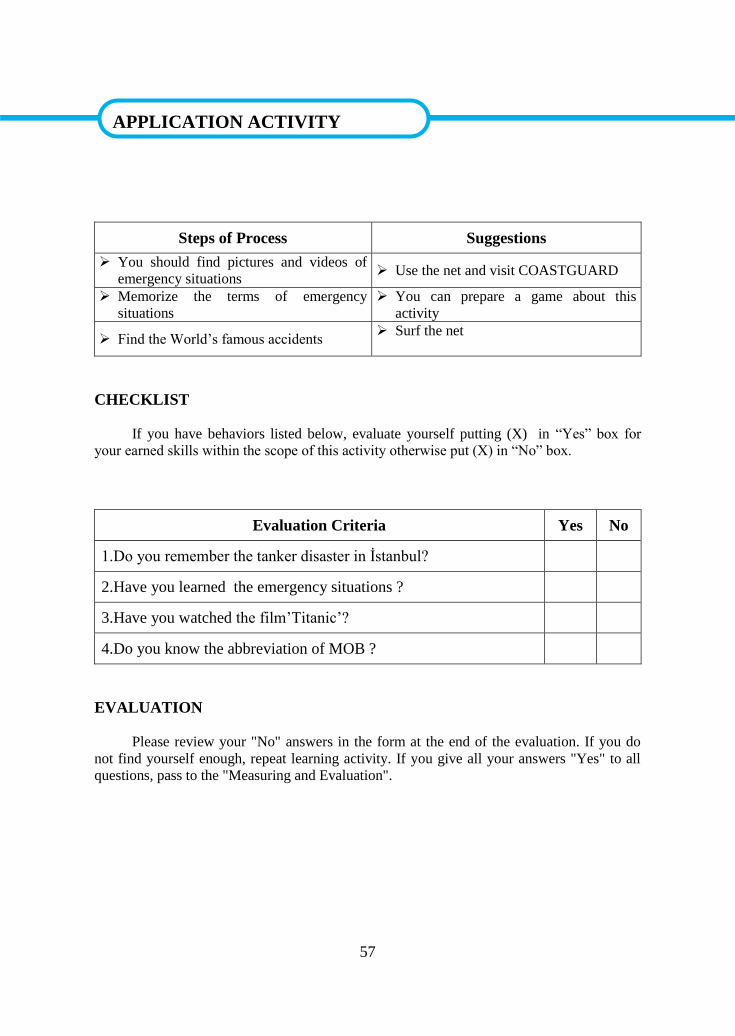
57
APPLICATION ACTIVITY
Steps of Process Suggestions
You should find pictures and videos of
emergency situations Use the net and visit COASTGUARD
Memorize the terms of emergency
situations
You can prepare a game about this
activity
Find the World’s famous accidents Surf the net
CHECKLIST
If you have behaviors listed below, evaluate yourself putting (X) in “Yes” box for
your earned skills within the scope of this activity otherwise put (X) in “No” box.
Evaluation Criteria Yes No
1.Do you remember the tanker disaster in İstanbul?
2.Have you learned the emergency situations ?
3.Have you watched the film’Titanic’?
4.Do you know the abbreviation of MOB ?
EVALUATION
Please review your "No" answers in the form at the end of the evaluation. If you do
not find yourself enough, repeat learning activity. If you give all your answers "Yes" to all
questions, pass to the "Measuring and Evaluation".
APPLICATION ACTIVITY
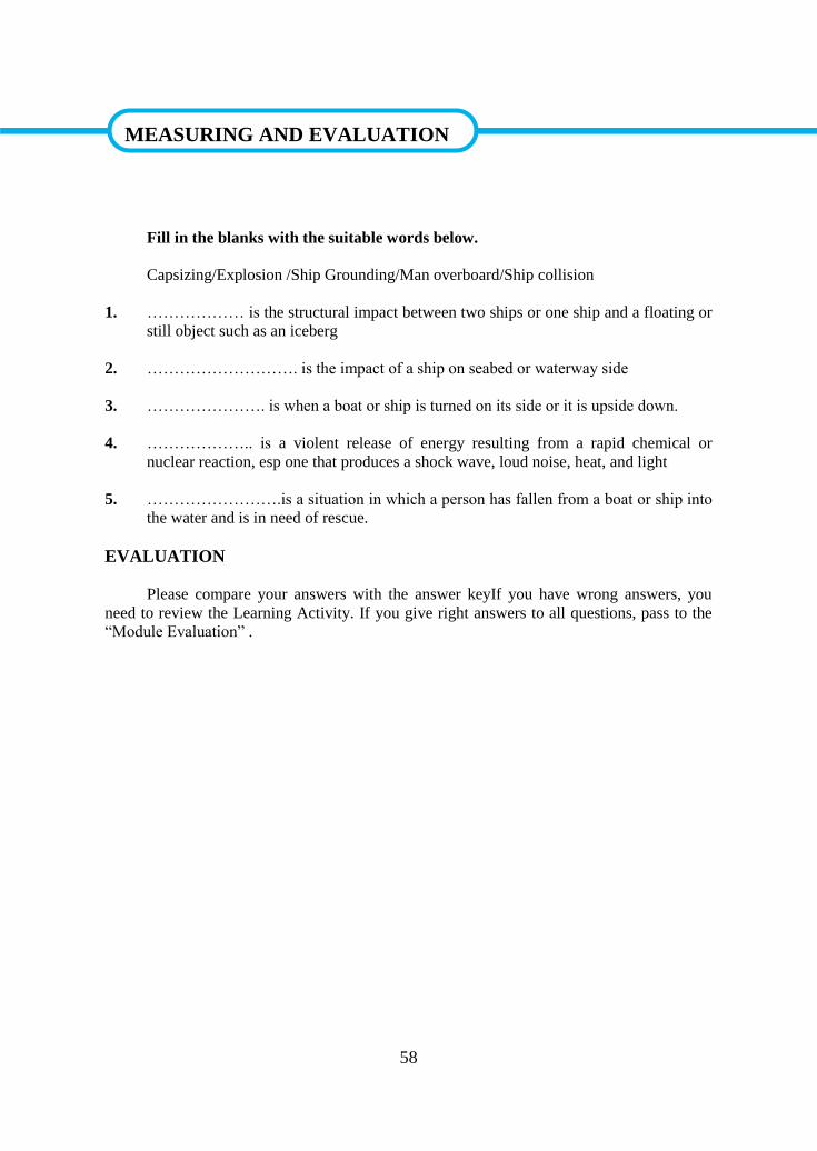
58
MEASURING AND EVALUATION
Fill in the blanks with the suitable words below.
Capsizing/Explosion /Ship Grounding/Man overboard/Ship collision
1. ……………… is the structural impact between two ships or one ship and a floating or
still object such as an iceberg
2. ………………………. is the impact of a ship on seabed or waterway side
3. …………………. is when a boat or ship is turned on its side or it is upside down.
4. ……………….. is a violent release of energy resulting from a rapid chemical or
nuclear reaction, esp one that produces a shock wave, loud noise, heat, and light
5. …………………….is a situation in which a person has fallen from a boat or ship into
the water and is in need of rescue.
EVALUATION
Please compare your answers with the answer keyIf you have wrong answers, you
need to review the Learning Activity. If you give right answers to all questions, pass to the
“Module Evaluation” .
MEASURING AND EVALUATION
59
MODULE EVALUATION
A. Choose the correct answer to the following questions
1. Which is not a respirator type?
A) The dust respirator
B) The positive pressure powered dust respirator
C) The cartridge-type respirator
D) The canister-type respirator
E) Resuscitation-type respirator
2. low pressure is symbolized with
A) LP B) L C) LO D) P E) W
3. Temperature is measured by a ……………………….
A) Barometer
B) Anemometer
C) Hygrometer
D) Ceilometer
E) Thermometer
4. What measures of heat energy in degrees?
A) Temperature
B) Pressure
C) Moisture
D) Thermometer
E) Precipation
5. The main causes of eye injury are:
A) Infra-red rays
B) Ultra-violet rays
C) Fog
D) Exposure to chemicals
E) Exposure to particles and foreign bodies.
6. ……………………….. is a massive cloud with great vertical development associated
with thunderstorms.
A) Cumulus (Cu)
B) Cumulonimbus (Cb)
C) Nimbostratus (Ns)
D) Stratocumulus(Sc)
E) Stratus (St)
MODULE EVALUATION
60
7. Which association below is not correct?
A) Continental Polar(CP)
B) Tropical (T)
C) Polar (P)
D) Antarctic (A)
E) Equatorial (E)
8. Much of the work of the deck department on board concerns the maintenance of the
ship and her fittings. This is the responsibility of ………………………….
A) Wiper
B) Third officer
C) Chief officer
D) Captain
E) Bosun
9. ………………………….. detail the times and heights of high and low waters for over
230 standard and 6000 secondary ports in the UK and Ireland, Europe, the Indian
Ocean, South China Sea and Pacific Ocean for each day of the year.
A) Tidal Stream Atlases
B) Sailing Directions
C) Fog Signals
D) Tide Tables
E) Manual of Tides
10. This symbol shows the……….
A) Ice crystals
B) Fog
C) Haze
D) Shower
E) Rain
B. Complete the sentences
1. A bump cap is simply_______________________________
2. The simplest form of ear protection is _______________________________
3. The main causes of eye injury are:_______________, __________________
______________________, ____________________.
4. The dust respirator gives protection against _____________________________
61
5. ___________________________ is a narrow basin or vessel that can be flooded to
allow a load to be floated in, then drained to allow that load to come to rest on a dry
platform.
6. Climate is defined as ______________________________________
7. A nautical chart is _______________________________________________
8. Meteorology is the science of ___________________________________
9. Ship grounding is _____________________________________________
10. Capsizing is ________________________________________________
EVALUATION
Please compare the answers with the answer key. If you have wrong answers, you
need to review the Learning Activity. If you give right answers to all questions, please
contact your teacher and pass to the next module.

62
ANSWER KEY
LEARNING ACTIVITY-1: ANSWER KEYS
1 True
2 False
3 True
4 False
5 True
LEARNING ACTIVITY-2: ANSWER KEYS
1 True
2 False
3 True
4 False
LEARNING ACTIVITY-3: ANSWER KEYS
1 A
2 B
3 D
4 C
5 E
LEARNING ACTIVITY-4: ANSWER KEYS
1 B
2 A
3 F
4 D
5 E
6 C
ANSWER KEY

63
LEARNING ACTIVITY-5: ANSWER KEYS
1 Ship Collision
2 Capsizing
3 Explosion
4 Ship Grounding
5 Man overboard
MODULE EVALUATION: ANSWER KEYS
A. Choose the correct answer to the following questions
1 E
2 B
3 E
4 A
5 C
6 B
7 D
8 C
9 D
10 A
B. Complete the sentences
1. A bump cap is simply an ordinary cap with a hard penetration-resistant shell.
2. The simplest form of ear protection is the ear plug.
3. The main causes of eye injury are: infra-red rays, ultra-violet rays, exposure to
chemicals, exposure to particles and foreign bodies.
4. The dust respirator gives protection against dusts and aerosol sprays
5. A dry dock is a narrow basin or vessel that can be flooded to allow a load to be
floated in, then drained to allow that load to come to rest on a dry platform.
6. Climate is defined as statistical weather information that describes the variation of
weather at a given place for a specified interval
7. A nautical chart is a graphic representation of a maritime area and adjacent
coastal regions.
64
8. Meteorology is the science of observing and predicting the weather.
9. Ship grounding is the impact of a ship on seabed or waterway side.
10. Capsizing is when a boat or ship is turned on its side or it is upside down

65
REFERENCES
SÜGEN Yücel, Kaptanın Kılavuzu, Akademi yayınları, İstanbul, 2007AKÇA
International Convention for the Safety of Life at Sea (SOLAS), 1974
Code Of Safe Working Practices For Merchant Seafarers, 2007
United Nations Convention on the Law of the Sea
http://www.imo.org (Erişim Tarihi: 03.08.2016/15:10)
https://www.admiralty.co.uk (Erişim Tarihi: 10.08.2016/11:15)
https://www.ukho.gov.uk (Erişim Tarihi: 11.08.2016/10:30)
http://www.shodb.gov.tr (Erişim Tarihi: 13.08.2016/13:50)
https://www.marineinsight.com (Erişim Tarihi: 13.08.2016/15:45)
REFERENCES


![Manevra Navei [Full]](https://img.pdfslide.tips/doc/110x75/55cf9849550346d03396bd3a/manevra-navei-full.jpg)