Embed Size (px)
Citation preview
Japan Atomic Energy Agency
日本原子力研究開発機構機関リポジトリ Japan Atomic Energy Agency Institutional Repository
Title Development of real-time rotating waveplate Stokes polarimeter using multi-order retardation for ITER poloidal polarimeter
Author(s) Imazawa Ryota, Kawano Yasunori, Ono Takehiro, Itami Kiyoshi
Citation Review of Scientific Instruments, 87(1), p.013503_1-013503_7
Text Version Publisher's Version
URL https://jopss.jaea.go.jp/search/servlet/search?5052152
DOI https://doi.org/10.1063/1.4939444
Right
This article may be downloaded for personal use only. Any other use requires prior permission of the author and the American Institute of Physics. The following article appeared in Review of Scientific Instruments and may be found at https://doi.org/10.1063/1.4939444.

Development of real-time rotating waveplate Stokes polarimeter using multi-orderretardation for ITER poloidal polarimeterR. Imazawa, Y. Kawano, T. Ono, and K. Itami Citation: Review of Scientific Instruments 87, 013503 (2016); doi: 10.1063/1.4939444 View online: http://dx.doi.org/10.1063/1.4939444 View Table of Contents: http://scitation.aip.org/content/aip/journal/rsi/87/1?ver=pdfcov Published by the AIP Publishing Articles you may be interested in Multihit two-dimensional charged-particle imaging system with real-time image processing at 1000 frames/s Rev. Sci. Instrum. 80, 013706 (2009); 10.1063/1.3062945 Ultrastable laser array at 633 nm for real-time dimensional metrology Rev. Sci. Instrum. 72, 2879 (2001); 10.1063/1.1374600 Faraday rotation densitometry for Large Helical Device Rev. Sci. Instrum. 72, 1073 (2001); 10.1063/1.1321742 Dual CO 2 laser polarimeter for Faraday rotation measurement in tokamak plasmas Rev. Sci. Instrum. 70, 714 (1999); 10.1063/1.1149470 Faraday rotation measurements on compact helical system by using a phase sensitive heterodynepolarimeter Rev. Sci. Instrum. 70, 730 (1999); 10.1063/1.1149314
This article is copyrighted as indicated in the article. Reuse of AIP content is subject to the terms at: http://scitationnew.aip.org/termsconditions. Downloaded to IP:
157.111.138.48 On: Tue, 12 Jan 2016 03:01:10
REVIEW OF SCIENTIFIC INSTRUMENTS 87, 013503 (2016)
Development of real-time rotating waveplate Stokes polarimeterusing multi-order retardation for ITER poloidal polarimeter
R. Imazawa,a) Y. Kawano, T. Ono, and K. ItamiJapan Atomic Energy Agency, 801-1 Mukoyama, Naka, Ibaraki, Japan
(Received 1 July 2015; accepted 19 December 2015; published online 8 January 2016)
The rotating waveplate Stokes polarimeter was developed for ITER (International ThermonuclearExperimental Reactor) poloidal polarimeter. The generalized model of the rotating waveplate Stokespolarimeter and the algorithm suitable for real-time field-programmable gate array (FPGA) process-ing were proposed. Since the generalized model takes into account each component associated withthe rotation of the waveplate, the Stokes parameters can be accurately measured even in unidealcondition such as non-uniformity of the waveplate retardation. Experiments using a He-Ne lasershowed that the maximum error and the precision of the Stokes parameter were 3.5% and 1.2%,respectively. The rotation speed of waveplate was 20 000 rpm and time resolution of measuring theStokes parameter was 3.3 ms. Software emulation showed that the real-time measurement of theStokes parameter with time resolution of less than 10 ms is possible by using several FPGA boards.Evaluation of measurement capability using a far-infrared laser which ITER poloidal polarimeter willuse concluded that measurement error will be reduced by a factor of nine. C 2016 AIP PublishingLLC. [http://dx.doi.org/10.1063/1.4939444]
I. INTRODUCTION
A poloidal polarimeter system will be installed inInternational Thermonuclear Experimental Reactor (ITER) toidentify a safety factor profile, q(r), in a plasma core region.1
The ITER poloidal polarimeter will use a far-infrared laser(wavelength is 119 µm) as a probing laser to measure both theFaraday effect and the Cotton-Mouton effect.2 The Faradayeffect rotates a polarization ellipse, and the Cotton-Moutoneffect changes an ellipticity of the polarization ellipse. Thus,a method for measuring both an orientation angle and anellipticity angle of a polarization state needs to be applied tothe ITER poloidal polarimeter. The authors have investigatedseveral polarization measurement techniques. Considering notonly a measurement capability but also reliability, availability,and maintainability, the authors concluded that a rotatingwaveplate Stokes polarimeter is most appropriate for the ITERpoloidal polarimeter.3
Baseline technical specifications of accuracy of measur-ing the polarization state are 1◦ for the orientation angleand 6◦ for the ellipticity angle. According to Ref. 2, thespecifications of the accuracy enable the poloidal polarimeterto identify q-profile of ITER inductive scenario plasma with10% accuracy. The accuracy includes all error sources suchas calibration error and polarization change caused by in-vessel retro-reflector. In order to allow larger error due tothe calibration error and the polarization change due tothe retro-reflector, the authors decided that target standarderrors of only the rotating waveplate Stokes polarimeter are0.05◦ for the orientation angle and 0.3◦ for the ellipticityangle. This target standard error would enable the ITERpoloidal polarimeter to contribute to successful experiments ofsteady-state operation scenario with negative magnetic shear
a)Electronic mail: [email protected]
configuration. Technical specifications of a time resolutionare 10 ms for off-line data analysis4 and 100 ms for real-timemeasurement, but a target specification of this study is 10 msfor the real-time measurement. (This is because a data analysisprocedure of the ITER poloidal polarimeter will avoid re-analyzing raw data to prepare off-line data after a long plasmadischarge of 1000 s. The raw data of 1000-s discharge couldbe more than 400 GB per viewing chord.)
The rotating waveplate Stokes polarimeter consists of arotating quarter waveplate and a linear polarizer. Detectorsignal is modulated by the rotation of the quarter waveplate andFourier analysis of the detector signal provides informationidentifying the polarization state. It is a well-known techniquein a field of polarimetry, but there is no rotating waveplateStokes polarimeter measuring at the time resolution of 10 ms inreal time. Theory of the rotating waveplate Stokes polarimeteris simple, but practice with high accuracy is not simple underunideal conditions such as concentric distribution of birefrin-gence and non-flatness and wedged shape of the waveplate.
This study will propose a generalized model of analyzingthe rotating waveplate Stokes polarimeter and an algorithmsuitable for real-time data analysis. The generalized modeltakes into account of the unideal conditions mentioned above.Experiments using a He-Ne laser (in other words, experimentsusing low waveplate quality) will demonstrate a performanceof the proposed methods and will give positive perspectivesof measurement capability using a far-infrared laser.
II. MEASUREMENT METHOD
A. Theory including unideal waveplateand right-angle mirror
The conventional rotating waveplate polarimeter needs ahigh-rotation-speed air spindle with a hollow axis. Althoughthe high-rotation-speed air spindle with a hollow axis is
0034-6748/2016/87(1)/013503/7/$30.00 87, 013503-1 © 2016 AIP Publishing LLC This article is copyrighted as indicated in the article. Reuse of AIP content is subject to the terms at: http://scitationnew.aip.org/termsconditions. Downloaded to IP:
157.111.138.48 On: Tue, 12 Jan 2016 03:01:10
013503-2 Imazawa et al. Rev. Sci. Instrum. 87, 013503 (2016)
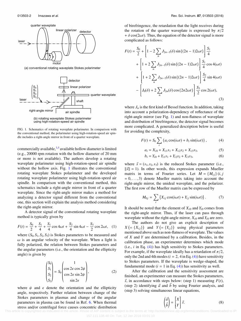
FIG. 1. Schematics of rotating waveplate polarimeter. In comparison withthe conventional method, the polarimeter using high-rotation-speed air spin-dle includes a right-angle mirror in front of a quarter waveplate.
commercially available,3,5 available hollow diameter is limited(e.g., 20000 rpm rotation with the hollow diameter of 20 mmor more is not available). The authors develop a rotatingwaveplate polarimeter using high-rotation-speed air spindlewithout the hollow axis. Fig. 1 illustrates the conventionalrotating waveplate Stokes polarimeter and the developedrotating waveplate polarimeter using high-rotation-speed airspindle. In comparison with the conventional method, thisschematics include a right-angle mirror in front of a quarterwaveplate. Since the right-angle mirror makes a method foranalyzing a detector signal different from the conventionalone, this section will explain the analysis method consideringthe right-angle mirror.
A detector signal of the conventional rotating waveplatemethod is typically given by
F(t) = S0
2+
S1
4+
S1
4cos 4ωt +
S2
4sin 4ωt − S3
2cos 2ωt, (1)
where (S0,S1,S2,S3) is Stokes parameters to be measured andω is an angular velocity of the waveplate. When a light isfully polarized, the relation between Stokes parameters andthe angular parameters (i.e., the orientation and the ellipticityangle) is given by
*.....,
S0
S1
S2
S3
+/////-
= S0
*.....,
1cos 2ϵ cos 2ψcos 2ϵ sin 2ψ
sin 2ϵ
+/////-
, (2)
where ψ and ϵ denote the orientation and the ellipticityangle, respectively. Further relation between change of theStokes parameters in plasmas and change of the angularparameters in plasma can be found in Ref. 6. When thermalstress and/or centrifugal force causes concentric distribution
of birefringence, the retardation that the light receives duringthe rotation of the quarter waveplate is expressed by π/2+ δ cos(2ωt). Thus, the equation of the detector signal is morecomplicated as follows:
F(t) = S0
2+
1 − 2
n
J2n−1(δ) sin{(2n − 1)2ωt}
S1
4
+
1 + 2
n
J2n−1(δ) sin{(2n − 1)2ωt}
S1
4cos 4(ωt)
+
1 + 2
n
J2n−1(δ) sin{(2n − 1)2ωt}
S2
4sin 4(ωt)
−J0(δ) + 2
n
J2n(δ) cos{2n2ωt}
S3
2cos 2(ωt),
(3)
where Jn is the first kind of Bessel function. In addition, takinginto account a polarization-dependency of reflectance of theright-angle mirror (see Fig. 1) and non-flatness of waveplateand distribution of birefringence, the detector signal becomesmore complicated. A generalized description below is usefulfor avoiding the complexity,
F(t) = S0
i
{ai cos(iωt) + bi sin(iωt)} , (4)
ai = Xi0 + Xi1s1 + Xi2s2 + Xi3s3, (5)bi = Yi0 + Yi1s1 + Yi2s2 + Yi3s3, (6)
where s⃗ = (s1, s2, s3) is the reduced Stokes parameter (i.e.,∥ s⃗∥ = 1). In other words, this expression expands Muellermatrix in terms of Fourier series. Let M = {Mi j} (i, j= 0, . . . ,3) denote Mueller matrix taking into account theright-angle mirror, the unideal waveplate, and the polarizer.The first row of the Mueller matrix can be expressed by
M0 j =i
�Xi j cos(iωt) + Yi j sin(iωt) . (7)
It should be noted that the element of Xi0 and Yi0 comes fromthe right-angle mirror. Thus, if the laser can pass throughwaveplate without the right-angle mirror, Xi0 and Yi0 are zero.
The authors do not give an explicit description ofX�= {Xi j}� and Y
�= {Yi j}� using physical parameters
mentioned above such as non-flatness of waveplate. The valuesof X and Y are determined by a calibration. Besides, in thecalibration phase, an experimenter determines which mode(i.e., i in Eq. (4)) has high sensitivity to Stokes parameters.For example, if the waveplate ideally has a retardation of π/2,only the 2nd and 4th modes (i = 2, 4 in Eq. (4)) have sensitivityto Stokes parameters. If the waveplate is wedge-shaped, thefundamental mode (i = 1 in Eq. (4)) has sensitivity as well.
After the calibration and the sensitivity assessment arefinished, an experimenter can measure the Stokes parameters,s⃗, in accordance with steps below: (step 1) measuring F(t),(step 2) identifying a⃗ and b⃗ by using Fourier analysis, and(step 3) solving simultaneous linear equations,
*,
a⃗b⃗+-=
XY
s⃗. (8)
This article is copyrighted as indicated in the article. Reuse of AIP content is subject to the terms at: http://scitationnew.aip.org/termsconditions. Downloaded to IP:
157.111.138.48 On: Tue, 12 Jan 2016 03:01:10
013503-3 Imazawa et al. Rev. Sci. Instrum. 87, 013503 (2016)
B. Algorithm of real-time data analysis suitablefor field-programmable gate array (FPGA)
It is necessary to identify Fourier coefficients, a⃗ and b⃗,accurately for the sake of accurate measurement of Stokesparameters. Intensity of low modes such as sin 2ωt orsin 4ωt is larger than that of high modes. Although FFT(fast Fourier transform) is well-known algorithm to identifyFourier coefficients, FFT does not suit for identifying lowmodes from measurement data during one rotation cycle (i.e.,0 ≤ t < 2π/ω). Only when the total number of samples canbe expressed by power of two, FFT of measurement dataduring one rotation provides accurate result of low modes.As described later (Section III), the total number of samplesduring one rotation cycle is 825 000 under experimentalconditions of this study and would lead to 10% error ofamplitude of fundamental mode even without measurementerror. Thus, the authors propose numerical calculation ofintegrals below,
ai =π
ω
2π/ω
0F(t) cos(iωt)dt,
bi =π
ω
2π/ω
0F(t) sin(iωt)dt .
(9)
As already mentioned in Section II A, since the sensitivityassessment is carried out during calibration, the total numberof i to be calculated is limited.
The final goal of this study is the real-time measurementof Stokes parameters as mentioned in Section I. It is preferableto calculate Eq. (9) in real time by using FPGA. Sinceair spindle has an encoder for accurate control of rotationspeed, A-phase and Z-phase signals of the encoder canbe used to obtain a phase angle of the rotating waveplateand the integral interval, respectively. The phase angle,ωt, is approximately given by ωt ≈ 2πk/2N , where k isa total number of A-phase pulses that are detected afterZ-phase pulse is detected, and N is a bit number of theencoder. The issue of real-time calculation of Eq. (9) inFPGA is that the computational cost of the sine and cosinefunctions is high. In order to avoid calculating the sine andcosine functions, the basis functions of the series expansionof Mueller matrix are changed from sin(iωt)/ cos(iωt) tosgn{sin(iωt)}/sgn{cos(iωt)}, where sgn(x) denotes a sign ofx. The detector signal is given by
F(t) = S0
i
[aisgn{cos(iωt)} + bisgn{sin(iωt)}] , (10)
where the definition of ai and bi is identical with Eqs. (5) and(6). Mathematical comments on the justification of the newbasis functions can be found in the Appendix of this paper.The value of sgn{sin(iωt)}/sgn{cos(iωt)} can be evaluatedby conditional branching, of which the computational cost ischeaper than that of the sine and cosine functions. For example,sgn{cos(2ωt)} can be evaluated as follows:
sgn{cos(2ωt)} =
1 0 ≤ k < 2N−2
−1 2N−2 ≤ k < 2N−1
1 2N−1 ≤ k < 3 · 2N−1
−1 3 · 2N−2 ≤ k < 2N
. (11)
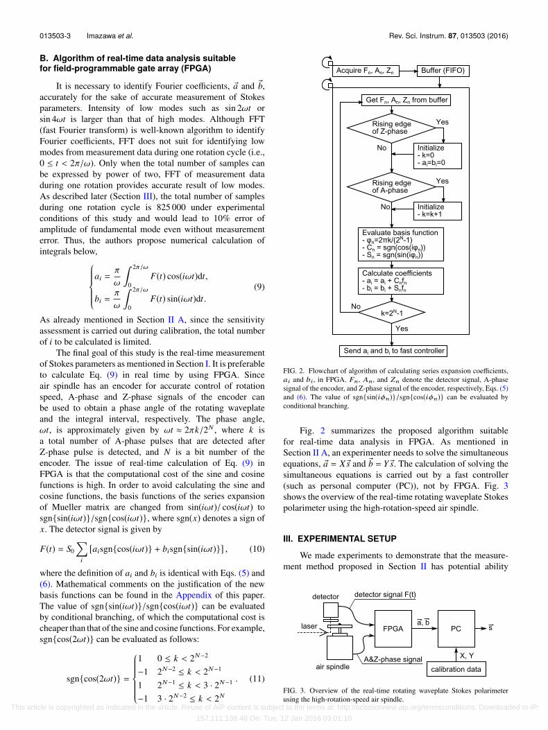
FIG. 2. Flowchart of algorithm of calculating series expansion coefficients,ai and bi, in FPGA. Fn, An, and Zn denote the detector signal, A-phasesignal of the encoder, and Z-phase signal of the encoder, respectively, Eqs. (5)and (6). The value of sgn{sin(iφn)}/sgn{cos(iφn)} can be evaluated byconditional branching.
Fig. 2 summarizes the proposed algorithm suitablefor real-time data analysis in FPGA. As mentioned inSection II A, an experimenter needs to solve the simultaneousequations, a⃗ = X s⃗ and b⃗ = Y s⃗. The calculation of solving thesimultaneous equations is carried out by a fast controller(such as personal computer (PC)), not by FPGA. Fig. 3shows the overview of the real-time rotating waveplate Stokespolarimeter using the high-rotation-speed air spindle.
III. EXPERIMENTAL SETUP
We made experiments to demonstrate that the measure-ment method proposed in Section II has potential ability
FIG. 3. Overview of the real-time rotating waveplate Stokes polarimeterusing the high-rotation-speed air spindle.
This article is copyrighted as indicated in the article. Reuse of AIP content is subject to the terms at: http://scitationnew.aip.org/termsconditions. Downloaded to IP:
157.111.138.48 On: Tue, 12 Jan 2016 03:01:10
013503-4 Imazawa et al. Rev. Sci. Instrum. 87, 013503 (2016)
of measuring Stokes parameters with high accuracy andhigh time resolution. ITER poloidal polarimeter uses a far-infrared laser (wavelength is 119 µm). However, since theauthors have no light source in far-infrared region, the authorsmade experiments by using a He-Ne laser (wavelength is632.8 nm). Major error sources of the rotating waveplatemethod are laser power fluctuation and oscillation of opticalcomponents which are not synchronized with the rotation ofthe waveplate. The laser power fluctuation of the He-Ne laserwas 1% during 1000 s. ITER poloidal polarimeter plans touse a far-infrared laser developed by Chubu University.7,8
The Chubu University achieved stability of 1% with aboutan output power of about 1 W for a long-term operationof 24 h.9 Thus, it is proper to use the He-Ne laser forthe experiments assessing the performance of the rotatingwaveplate polarimeter. Regarding unsynchronized oscillationof components, measurement error using the He-Ne laser islarger than that using the far-infrared laser because amplitudeof unsynchronized oscillation normalized by wavelengthof the He-Ne laser is larger than that of the far-infraredlaser.
A. Design of quartz waveplate
A quarter waveplate for both the He-Ne laser and the far-infrared laser is made of quartz. Since the quarter waveplatewill be rotated in the manner shown in Fig. 1, a shape of thewaveplate is a disk and has a hole at the center for fixation. Forthe sake of easier fabrication of the hole, a thickness of quartzneeds to be around 2.5 mm. That is to say, it is inevitable to usemulti-order quarter waveplate for the rotating waveplate withconfiguration shown in Fig. 1. The specifications of the quarterwaveplate used in this experiment are as follows: diameter of50 mm, hole diameter (D) of 6 mm, parallelism (θ) of 5 s, andflatness of 0.158 µm. Thus, key parameters normalized bywavelength, λ(= 632.8 nm), are as follows: retardation of λ/4(36th order), flatness of λ/4, and wedge height (h = D tan θ)of 1.9λ.
When the quarter waveplate rotates, the maximum stressis applied to the circumference of the central hole. Assumingthat the allowable stress of quartz is the same as that offused silica, the allowable stress is approximately 40 MPa.Setting a safety margin to 10, the quarter waveplate with thesize mentioned above needs to rotate at a speed of less than23 000 rpm.
B. Air spindle
An air spindle of ShinMaywa Industries, Ltd. (SPM27H)was used. The air spindle can rotate at a maximum speedof 20 000 rpm and the rotation speed fluctuation is 0.01%.Resolution of the encoder is 9 bits. The unsynchronized run-out of the air spindle shaft was 6 nm in the axial direction and7 nm in the radial direction. The unsynchronized run-out ofthe quarter waveplate rotated by the air spindle is unknown.
Since the air spindle rotation speed is 20 000 rpm, thetime resolution of measuring the Stokes parameters is 3.3 ms(333 Hz). It is better than the requirement of ITER poloidalpolarimeter (10 ms).
C. Analog-digital converter (ADC) resolution
In ITER, instrumentation and control devices are stan-dardized and candidates of the FPGA boards are limited.ITER poloidal polarimeter plans to use a FPGA instrumentwith sampling rate of 250 MHz and ADC voltage resolutionof 14 bits. However, the authors do not have this FPGAinstrument. This study uses an oscilloscope with samplingrate of 250 MHz and voltage resolution of 11 bits in orderto verify the high-speed Stokes parameter measurement off-line. Assessment of FPGA performance will be discussed inSection V by using software emulation.
IV. EXPERIMENTAL RESULTS
A. Contribution of centrifugal force to birefringence
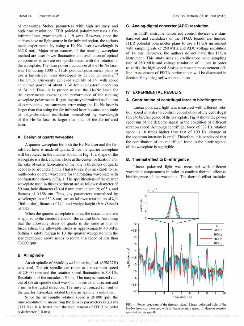
Linear polarized light was measured with different rota-tion speed in order to confirm contribution of the centrifugalforce to birefringence of the waveplate. Fig. 4 shows the powerspectrum of the detector signal in the condition of differentrotation speed. Although centrifugal force of 333 Hz rotationspeed is 10 times higher than that of 100 Hz, change ofthe spectrum intensity is small. Therefore, it is concluded thatthe contribution of the centrifugal force to the birefringenceof the waveplate is negligible.
B. Thermal effect to birefringence
Linear polarized light was measured with differentwaveplate temperatures in order to confirm thermal effect tobirefringence of the waveplate. The thermal effect includes
FIG. 4. Power spectrum of the detector signal. Linear polarized light of theHe-Ne laser was measured with different rotation speed. fc denotes rotationspeed of the air spindle.
This article is copyrighted as indicated in the article. Reuse of AIP content is subject to the terms at: http://scitationnew.aip.org/termsconditions. Downloaded to IP:
157.111.138.48 On: Tue, 12 Jan 2016 03:01:10
013503-5 Imazawa et al. Rev. Sci. Instrum. 87, 013503 (2016)
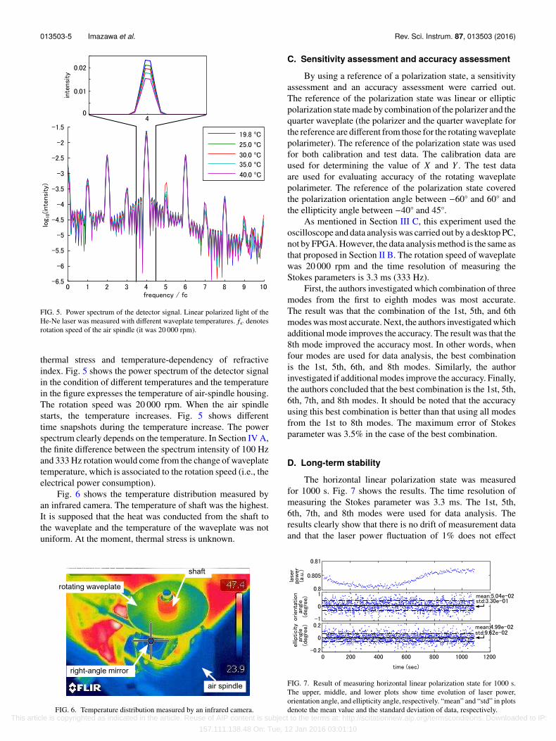
FIG. 5. Power spectrum of the detector signal. Linear polarized light of theHe-Ne laser was measured with different waveplate temperatures. fc denotesrotation speed of the air spindle (it was 20 000 rpm).
thermal stress and temperature-dependency of refractiveindex. Fig. 5 shows the power spectrum of the detector signalin the condition of different temperatures and the temperaturein the figure expresses the temperature of air-spindle housing.The rotation speed was 20 000 rpm. When the air spindlestarts, the temperature increases. Fig. 5 shows differenttime snapshots during the temperature increase. The powerspectrum clearly depends on the temperature. In Section IV A,the finite difference between the spectrum intensity of 100 Hzand 333 Hz rotation would come from the change of waveplatetemperature, which is associated to the rotation speed (i.e., theelectrical power consumption).
Fig. 6 shows the temperature distribution measured byan infrared camera. The temperature of shaft was the highest.It is supposed that the heat was conducted from the shaft tothe waveplate and the temperature of the waveplate was notuniform. At the moment, thermal stress is unknown.
FIG. 6. Temperature distribution measured by an infrared camera.
C. Sensitivity assessment and accuracy assessment
By using a reference of a polarization state, a sensitivityassessment and an accuracy assessment were carried out.The reference of the polarization state was linear or ellipticpolarization state made by combination of the polarizer and thequarter waveplate (the polarizer and the quarter waveplate forthe reference are different from those for the rotating waveplatepolarimeter). The reference of the polarization state was usedfor both calibration and test data. The calibration data areused for determining the value of X and Y . The test dataare used for evaluating accuracy of the rotating waveplatepolarimeter. The reference of the polarization state coveredthe polarization orientation angle between −60◦ and 60◦ andthe ellipticity angle between −40◦ and 45◦.
As mentioned in Section III C, this experiment used theoscilloscope and data analysis was carried out by a desktop PC,not by FPGA. However, the data analysis method is the same asthat proposed in Section II B. The rotation speed of waveplatewas 20 000 rpm and the time resolution of measuring theStokes parameters is 3.3 ms (333 Hz).
First, the authors investigated which combination of threemodes from the first to eighth modes was most accurate.The result was that the combination of the 1st, 5th, and 6thmodes was most accurate. Next, the authors investigated whichadditional mode improves the accuracy. The result was that the8th mode improved the accuracy most. In other words, whenfour modes are used for data analysis, the best combinationis the 1st, 5th, 6th, and 8th modes. Similarly, the authorinvestigated if additional modes improve the accuracy. Finally,the authors concluded that the best combination is the 1st, 5th,6th, 7th, and 8th modes. It should be noted that the accuracyusing this best combination is better than that using all modesfrom the 1st to 8th modes. The maximum error of Stokesparameter was 3.5% in the case of the best combination.
D. Long-term stability
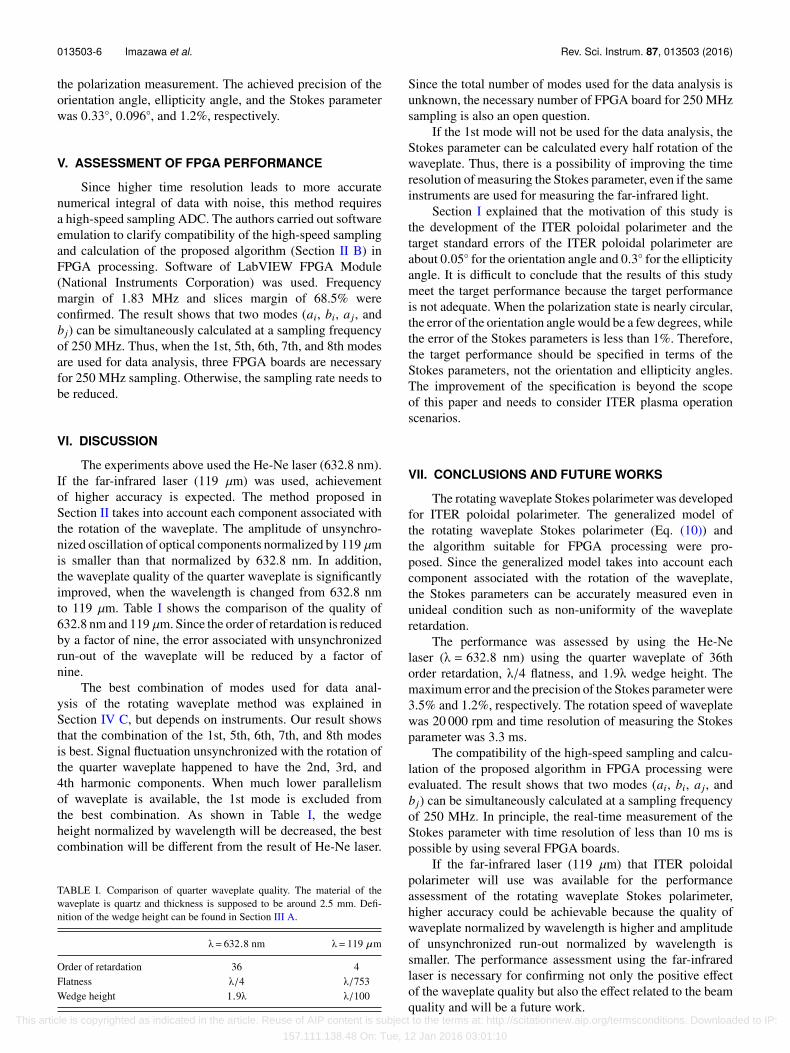
The horizontal linear polarization state was measuredfor 1000 s. Fig. 7 shows the results. The time resolution ofmeasuring the Stokes parameter was 3.3 ms. The 1st, 5th,6th, 7th, and 8th modes were used for data analysis. Theresults clearly show that there is no drift of measurement dataand that the laser power fluctuation of 1% does not effect
FIG. 7. Result of measuring horizontal linear polarization state for 1000 s.The upper, middle, and lower plots show time evolution of laser power,orientation angle, and ellipticity angle, respectively. “mean” and “std” in plotsdenote the mean value and the standard deviation of data, respectively.
This article is copyrighted as indicated in the article. Reuse of AIP content is subject to the terms at: http://scitationnew.aip.org/termsconditions. Downloaded to IP:
157.111.138.48 On: Tue, 12 Jan 2016 03:01:10
013503-6 Imazawa et al. Rev. Sci. Instrum. 87, 013503 (2016)
the polarization measurement. The achieved precision of theorientation angle, ellipticity angle, and the Stokes parameterwas 0.33◦, 0.096◦, and 1.2%, respectively.
V. ASSESSMENT OF FPGA PERFORMANCE
Since higher time resolution leads to more accuratenumerical integral of data with noise, this method requiresa high-speed sampling ADC. The authors carried out softwareemulation to clarify compatibility of the high-speed samplingand calculation of the proposed algorithm (Section II B) inFPGA processing. Software of LabVIEW FPGA Module(National Instruments Corporation) was used. Frequencymargin of 1.83 MHz and slices margin of 68.5% wereconfirmed. The result shows that two modes (ai, bi, a j, andbj) can be simultaneously calculated at a sampling frequencyof 250 MHz. Thus, when the 1st, 5th, 6th, 7th, and 8th modesare used for data analysis, three FPGA boards are necessaryfor 250 MHz sampling. Otherwise, the sampling rate needs tobe reduced.
VI. DISCUSSION
The experiments above used the He-Ne laser (632.8 nm).If the far-infrared laser (119 µm) was used, achievementof higher accuracy is expected. The method proposed inSection II takes into account each component associated withthe rotation of the waveplate. The amplitude of unsynchro-nized oscillation of optical components normalized by 119 µmis smaller than that normalized by 632.8 nm. In addition,the waveplate quality of the quarter waveplate is significantlyimproved, when the wavelength is changed from 632.8 nmto 119 µm. Table I shows the comparison of the quality of632.8 nm and 119 µm. Since the order of retardation is reducedby a factor of nine, the error associated with unsynchronizedrun-out of the waveplate will be reduced by a factor ofnine.
The best combination of modes used for data anal-ysis of the rotating waveplate method was explained inSection IV C, but depends on instruments. Our result showsthat the combination of the 1st, 5th, 6th, 7th, and 8th modesis best. Signal fluctuation unsynchronized with the rotation ofthe quarter waveplate happened to have the 2nd, 3rd, and4th harmonic components. When much lower parallelismof waveplate is available, the 1st mode is excluded fromthe best combination. As shown in Table I, the wedgeheight normalized by wavelength will be decreased, the bestcombination will be different from the result of He-Ne laser.
TABLE I. Comparison of quarter waveplate quality. The material of thewaveplate is quartz and thickness is supposed to be around 2.5 mm. Defi-nition of the wedge height can be found in Section III A.
λ= 632.8 nm λ= 119 µm
Order of retardation 36 4Flatness λ/4 λ/753Wedge height 1.9λ λ/100
Since the total number of modes used for the data analysis isunknown, the necessary number of FPGA board for 250 MHzsampling is also an open question.
If the 1st mode will not be used for the data analysis, theStokes parameter can be calculated every half rotation of thewaveplate. Thus, there is a possibility of improving the timeresolution of measuring the Stokes parameter, even if the sameinstruments are used for measuring the far-infrared light.
Section I explained that the motivation of this study isthe development of the ITER poloidal polarimeter and thetarget standard errors of the ITER poloidal polarimeter areabout 0.05◦ for the orientation angle and 0.3◦ for the ellipticityangle. It is difficult to conclude that the results of this studymeet the target performance because the target performanceis not adequate. When the polarization state is nearly circular,the error of the orientation angle would be a few degrees, whilethe error of the Stokes parameters is less than 1%. Therefore,the target performance should be specified in terms of theStokes parameters, not the orientation and ellipticity angles.The improvement of the specification is beyond the scopeof this paper and needs to consider ITER plasma operationscenarios.
VII. CONCLUSIONS AND FUTURE WORKS
The rotating waveplate Stokes polarimeter was developedfor ITER poloidal polarimeter. The generalized model ofthe rotating waveplate Stokes polarimeter (Eq. (10)) andthe algorithm suitable for FPGA processing were pro-posed. Since the generalized model takes into account eachcomponent associated with the rotation of the waveplate,the Stokes parameters can be accurately measured even inunideal condition such as non-uniformity of the waveplateretardation.
The performance was assessed by using the He-Nelaser (λ = 632.8 nm) using the quarter waveplate of 36thorder retardation, λ/4 flatness, and 1.9λ wedge height. Themaximum error and the precision of the Stokes parameter were3.5% and 1.2%, respectively. The rotation speed of waveplatewas 20 000 rpm and time resolution of measuring the Stokesparameter was 3.3 ms.
The compatibility of the high-speed sampling and calcu-lation of the proposed algorithm in FPGA processing wereevaluated. The result shows that two modes (ai, bi, a j, andbj) can be simultaneously calculated at a sampling frequencyof 250 MHz. In principle, the real-time measurement of theStokes parameter with time resolution of less than 10 ms ispossible by using several FPGA boards.
If the far-infrared laser (119 µm) that ITER poloidalpolarimeter will use was available for the performanceassessment of the rotating waveplate Stokes polarimeter,higher accuracy could be achievable because the quality ofwaveplate normalized by wavelength is higher and amplitudeof unsynchronized run-out normalized by wavelength issmaller. The performance assessment using the far-infraredlaser is necessary for confirming not only the positive effectof the waveplate quality but also the effect related to the beamquality and will be a future work.
This article is copyrighted as indicated in the article. Reuse of AIP content is subject to the terms at: http://scitationnew.aip.org/termsconditions. Downloaded to IP:
157.111.138.48 On: Tue, 12 Jan 2016 03:01:10
013503-7 Imazawa et al. Rev. Sci. Instrum. 87, 013503 (2016)
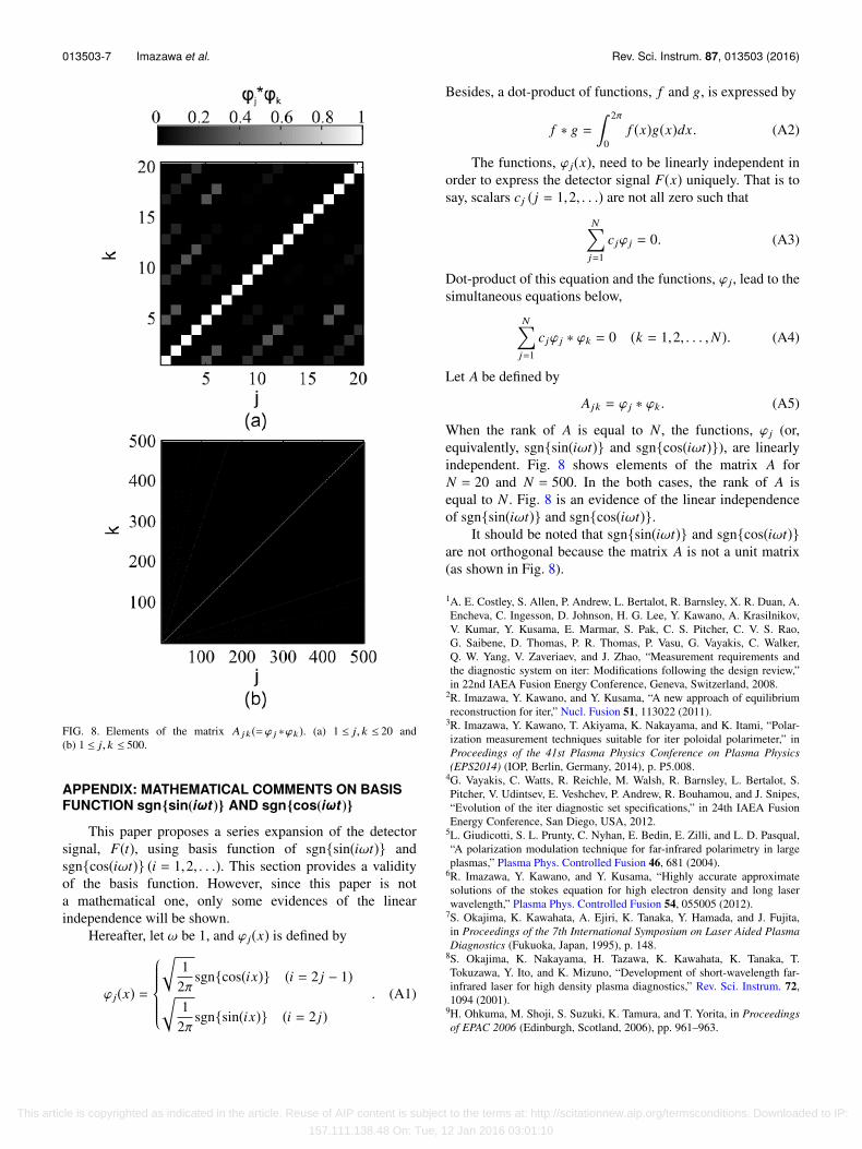
FIG. 8. Elements of the matrix A jk(=ϕ j ∗ϕk). (a) 1 ≤ j, k ≤ 20 and(b) 1 ≤ j, k ≤ 500.
APPENDIX: MATHEMATICAL COMMENTS ON BASISFUNCTION sgn{sin(iωt )} AND sgn{cos(iωt )}
This paper proposes a series expansion of the detectorsignal, F(t), using basis function of sgn{sin(iωt)} andsgn{cos(iωt)} (i = 1,2, . . .). This section provides a validityof the basis function. However, since this paper is nota mathematical one, only some evidences of the linearindependence will be shown.
Hereafter, let ω be 1, and ϕ j(x) is defined by
ϕ j(x) =
1
2πsgn{cos(ix)} (i = 2 j − 1)
12π
sgn{sin(ix)} (i = 2 j). (A1)
Besides, a dot-product of functions, f and g, is expressed by
f ∗ g = 2π
0f (x)g(x)dx. (A2)
The functions, ϕ j(x), need to be linearly independent inorder to express the detector signal F(x) uniquely. That is tosay, scalars cj ( j = 1,2, . . .) are not all zero such that
Nj=1
cjϕ j = 0. (A3)
Dot-product of this equation and the functions, ϕ j, lead to thesimultaneous equations below,
Nj=1
cjϕ j ∗ ϕk = 0 (k = 1,2, . . . ,N). (A4)
Let A be defined by
Ajk = ϕ j ∗ ϕk . (A5)
When the rank of A is equal to N , the functions, ϕ j (or,equivalently, sgn{sin(iωt)} and sgn{cos(iωt)}), are linearlyindependent. Fig. 8 shows elements of the matrix A forN = 20 and N = 500. In the both cases, the rank of A isequal to N . Fig. 8 is an evidence of the linear independenceof sgn{sin(iωt)} and sgn{cos(iωt)}.
It should be noted that sgn{sin(iωt)} and sgn{cos(iωt)}are not orthogonal because the matrix A is not a unit matrix(as shown in Fig. 8).
1A. E. Costley, S. Allen, P. Andrew, L. Bertalot, R. Barnsley, X. R. Duan, A.Encheva, C. Ingesson, D. Johnson, H. G. Lee, Y. Kawano, A. Krasilnikov,V. Kumar, Y. Kusama, E. Marmar, S. Pak, C. S. Pitcher, C. V. S. Rao,G. Saibene, D. Thomas, P. R. Thomas, P. Vasu, G. Vayakis, C. Walker,Q. W. Yang, V. Zaveriaev, and J. Zhao, “Measurement requirements andthe diagnostic system on iter: Modifications following the design review,”in 22nd IAEA Fusion Energy Conference, Geneva, Switzerland, 2008.
2R. Imazawa, Y. Kawano, and Y. Kusama, “A new approach of equilibriumreconstruction for iter,” Nucl. Fusion 51, 113022 (2011).
3R. Imazawa, Y. Kawano, T. Akiyama, K. Nakayama, and K. Itami, “Polar-ization measurement techniques suitable for iter poloidal polarimeter,” inProceedings of the 41st Plasma Physics Conference on Plasma Physics(EPS2014) (IOP, Berlin, Germany, 2014), p. P5.008.
4G. Vayakis, C. Watts, R. Reichle, M. Walsh, R. Barnsley, L. Bertalot, S.Pitcher, V. Udintsev, E. Veshchev, P. Andrew, R. Bouhamou, and J. Snipes,“Evolution of the iter diagnostic set specifications,” in 24th IAEA FusionEnergy Conference, San Diego, USA, 2012.
5L. Giudicotti, S. L. Prunty, C. Nyhan, E. Bedin, E. Zilli, and L. D. Pasqual,“A polarization modulation technique for far-infrared polarimetry in largeplasmas,” Plasma Phys. Controlled Fusion 46, 681 (2004).
6R. Imazawa, Y. Kawano, and Y. Kusama, “Highly accurate approximatesolutions of the stokes equation for high electron density and long laserwavelength,” Plasma Phys. Controlled Fusion 54, 055005 (2012).
7S. Okajima, K. Kawahata, A. Ejiri, K. Tanaka, Y. Hamada, and J. Fujita,in Proceedings of the 7th International Symposium on Laser Aided PlasmaDiagnostics (Fukuoka, Japan, 1995), p. 148.
8S. Okajima, K. Nakayama, H. Tazawa, K. Kawahata, K. Tanaka, T.Tokuzawa, Y. Ito, and K. Mizuno, “Development of short-wavelength far-infrared laser for high density plasma diagnostics,” Rev. Sci. Instrum. 72,1094 (2001).
9H. Ohkuma, M. Shoji, S. Suzuki, K. Tamura, and T. Yorita, in Proceedingsof EPAC 2006 (Edinburgh, Scotland, 2006), pp. 961–963.
This article is copyrighted as indicated in the article. Reuse of AIP content is subject to the terms at: http://scitationnew.aip.org/termsconditions. Downloaded to IP:
157.111.138.48 On: Tue, 12 Jan 2016 03:01:10