Embed Size (px)
Citation preview

��
�������
���������������� ��� ���

����������������� �� ����������������� ����������� ��� ������ �� �
������� �� �
�� � �� �
���������� �!"� #� �
$��%&�'!%(��)��(�' ""� #� �
� � �
� �$����� �������$��� *� �
+�,��" ���-- (�����.� *� �
� � �
�� ��$������ �� �
��� '!��)����/���(��)���'/��,� � �� �
��-- (����/� �� �
���)- 0��!'���&&" !����/��-��0��!��,� � �� �
��%(0��!'���&&" !����/��"" �1-,��( ""0��!��,� ���(�$%-!��- ��!(��2��������-,�
�� � �
��� '!��)����/��!! (������,� � �� � � �
�3�0��!'���&&" !����/��"" �1-,��( ""0��!��,� ���(����)- ��!(��2��������-,�
�� � ����������� � �4�
������ '!��)����/��%"� 2� �!( �-�! ����/� �� � ����� �5$� ��������� ������� � �6�
� � � �'/ -��-�! 2������ �6�
����������� ����� � ��� � �!���- ""��! -������ �*�
�!��2�(2�� (� "������ ��� � ����!���- ""� �*�
� � � ����� (� "��!���- ""������ �*�
���7����� ����� � �8� � ����� (� "��!���- ""������ �*�
� �9,�� (� "������ �8� � 4���" (� "��!���- ""������ �*�
� � � � �
� �����������5�� ����� � ��� � ��� ������� �� ����� ���
��)���!( �)!��:��;��(�9 ������ ��� � ��+�����7������� ���
���"!������ ��� � �-�"!�'���-��� 2 (������ ���
� � � � �
��� ������� ������� � ��� � �����$����� � 8��
� ����������0���)������ ��� � �!��2�(2��!(��)�!���2�� �!��!!�'�� �!������ 8��
��� '!��)����/��"" �1-,� �#� � +�2 ���!�%(��!(��)�!���2�� �!��!!�'�� �!������ 8��
� � � ��%1- 0��!'��� �!��!!�'�� �!"� 8��
� � ��%1- 0��!'���!(��)�!��!!�'�� �!"� 8��
� � � �
� � �<������� ��� � 88�
� � �!��2�(2��=! �2 2����"� 88�
� � �!!�'�� �!���- ���> "� 88�
� � � �
��� �� ��5$���0��0�����������$���� 8��
��%1- ��!(��)�!��%)"� 8��
��%1- �� �!��%)"� 8��
+�2 ���--��%)"� 8��
� �
�����$����� ��� ����� ��� 8��
� �
�� � �������������������� � 8#�
� �
�
� �
�� ������� 84�
� � � �������� '!��)����-� 84�
� � � ��-- (�����������=!(�'!�(� 84�
� � � � �
� � � ��<� 86�
� � � � �
� �2�%"����-� ��(!?2�����2'����@'����
� '/�%"��%!����!� �3 1�333@2�����2'����@'���
@=
(317) 638-6431
Nothing Outlasts a Diamond.
DIAMOND CHAIN HISTORY
Arthur C. Newby, Edward C. Fletcher and Glenn Howe, with a $5,000 investment, started
what was to become the Diamond®Chain Company by forming The Indianapolis Chain &
Stamping Company on December 24, 1890. They took the diamond as their
trademark because it symbolized perfection and acted as a constant
reminder of their endeavor.
In its humble beginnings, The Indianapolis Chain &
Stamping Company (IC&SC) specialized in bicycle chain. As
one of the first companies in the United States to produce
bicycle chain, IC&SC prospered, outgrowing its original quar-
ters and moving to larger facilities in 1892.
In 1901, when the bicycle chain business slumped, IC&SC
rebounded by developing and introducing to industry a twin-
roller roller chain.
From December 17, 1903, when Diamond chain was used on
the Wright brothers’ first flying machine, to the present, Diamond Chain has been
a major supplier of chain not just for aircraft, but for power transmission and product convey-
ing throughout manufacturing industries.
In 1950 Diamond Chain was acquired by American Steel Foundries, Inc. – the largest steel
foundry in the world, and in 1962 the name of the parent company was changed to AMSTED
Industries Incorporated.
During Diamond’s many years of producing the highest quality roller chain they have tested,
examined and discovered many developments which have significantly increased the perfor-
mance of their roller chains. These developments have rarely become “product lines” but
rather, “product improvements” which have been incorporated into daily
production so that all customers can benefit, without special requests
or premium prices.
In addition to continued product improvement, Diamond
has introduced a detailed roller chain Drive Selection
Software program. This software will improve the way chain
is specified by engineers and designers by simplifying a
multitude of sometimes difficult calculations and equations.
In today’s environment, Diamond, while focusing on
the increased use of technology, still operates under the same
3

4
inventive, grassroots philosophy it was founded on – providing its customers
customers with a high-quality product possessing the best balance
with high-quality product processing the best of performance, reliability
price and delivery that meet or exceed their requirements.
If you’re looking for the best roller
chain for the job, it’ll pay to take acloser
look at Diamond roller chain. Diamond roller chain may look
like your everyday chain, but upon closer inspection the unique
differences that make Diamond chain better become evident.
From the strict attention to detail we devote to every chain
design, to the extra steps we take during fabrication and assem-
bly operations, those differences really add up. We build long
life, lasting value and enduring customer relationships into every
link of chain...that is the Diamond difference.
Over the years we’ve produced tens of thousands of types of roller chain
for a wide variety of applications from oil field and deco ovens,
to conveyors and combines. So, if your application calls for some
special attention, our application engineers can easily help you
find that lasting solution.
Please, take a closer look at Diamond roller chain...we do.
That closer look is what makes ours better than other chains.
And what you can’t see, you can experience with improved
performance – which means less downtime, less repair costs,
and increased productivity. Those are just
some of the differences that a Diamond chain makes.
ISO 9001
Building high-quality roller chain is a matter of demanding
precision – a matter of establishing critical parameters, both in
component fabrication and final assembly, and monitoring them
to ensure that they are maintained.
ISO 9001 certification is awarded to companies that develop,
and consistently adhere to, a well-documented quality system. ISO 9001 requires compliance
with 20 elements, some of which include customer
service, contract review, manufacturing procedures, and product design and
development. Diamond is ISO 9001 certified. That means you can be sure that Diamond chain
is consistently manufactured following detailed processes developed by Diamond and proven to
produce some of the longest running and best performing roller chain.
5
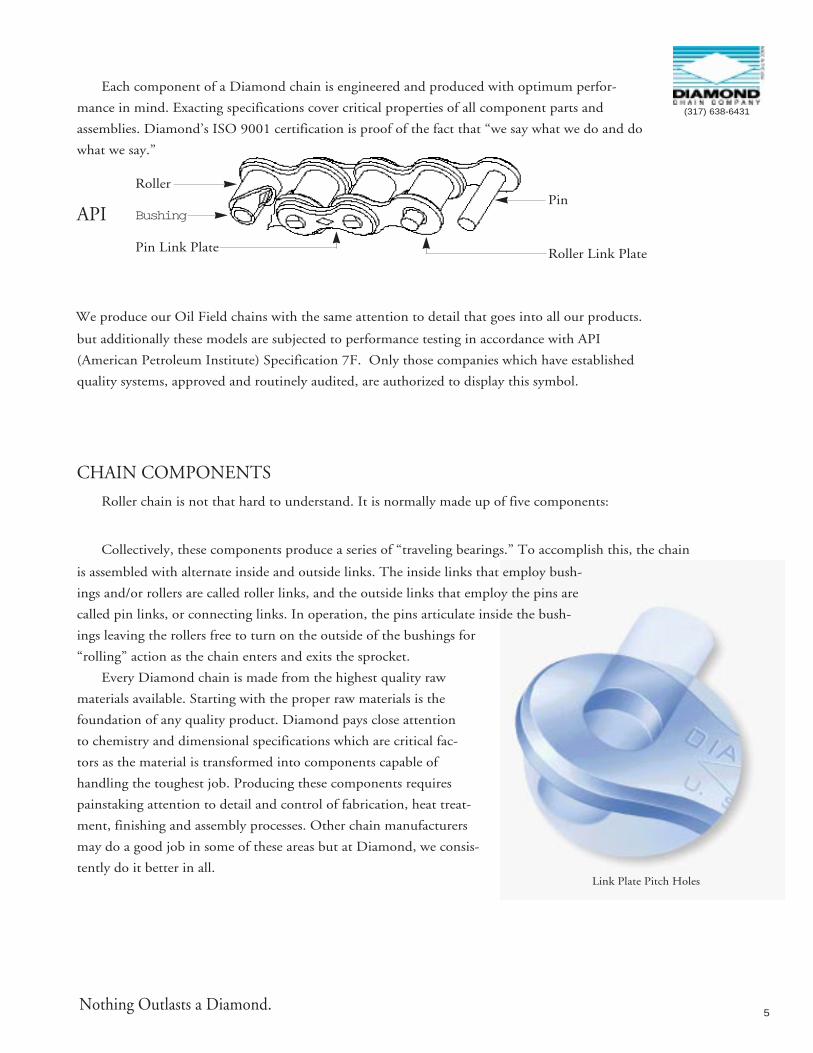
Each component of a Diamond chain is engineered and produced with optimum perfor-
mance in mind. Exacting specifications cover critical properties of all component parts and
assemblies. Diamond’s ISO 9001 certification is proof of the fact that “we say what we do and do
what we say.”
API
We produce our Oil Field chains with the same attention to detail that goes into all our products.
but additionally these models are subjected to performance testing in accordance with API
(American Petroleum Institute) Specification 7F. Only those companies which have established
quality systems, approved and routinely audited, are authorized to display this symbol.
CHAIN COMPONENTS
Roller chain is not that hard to understand. It is normally made up of five components:
Collectively, these components produce a series of “traveling bearings.” To accomplish this, the chain
is assembled with alternate inside and outside links. The inside links that employ bush-
ings and/or rollers are called roller links, and the outside links that employ the pins are
called pin links, or connecting links. In operation, the pins articulate inside the bush-
ings leaving the rollers free to turn on the outside of the bushings for
“rolling” action as the chain enters and exits the sprocket.
Every Diamond chain is made from the highest quality raw
materials available. Starting with the proper raw materials is the
foundation of any quality product. Diamond pays close attention
to chemistry and dimensional specifications which are critical fac-
tors as the material is transformed into components capable of
handling the toughest job. Producing these components requires
painstaking attention to detail and control of fabrication, heat treat-
ment, finishing and assembly processes. Other chain manufacturers
may do a good job in some of these areas but at Diamond, we consis-
tently do it better in all.
Roller Link Plate
Roller
Pin Link Plate
BushingPin
(317) 638-6431
Nothing Outlasts a Diamond.
Link Plate Pitch Holes

6
MANUFACTURING PROCESS
Diamond jewels are sought out because of their
enduring perfection. The same argument can be made
for a Diamond chain. But, unlike precious gems,
Diamond chain is readily available directly from us or
your authorized Diamond distributor.
The process of manufacturing the longest lasting chain
begins by purchasing the materials to our detailed specifications.
We do this because we must specify chemistry, dimensional size and
even the direction of the grain in order to fabricate components capable of performing to
your expectations.
Transforming these raw materials into individual components that meet our high stan-
dards is no easy task. Again, we’ve learned that attention to detail is a key to achieving the
desired result, which is the user’s
satisfaction. Some of the steps taken to provide this satisfaction are:
Link plate pitch holes are produced using a three-part process to
create a polished hole with maximum bearing area and minimal surface
imperfection. Maximum bearing area increases chain integrity, and a
smooth surface within the pitch hole maximizes the ability to han-
dle heavy loads,
especially in fatigue-sensitive applications. Even with the three-
part process,
link plates are left with a small “breakout” area. To minimize the
effects of this, Diamond provides a unique identifying feature on
our 19.10mm through 57.20mm pitch, standard and heavy series
ANSI chains. This identifying feature, a beveled edge, is unique to
Diamond, and we use it to orient and assemble the link plates in a direc-
tion which minimizes negative effects of the breakout.
Many years ago, Diamond discovered that forming bushings and rollers from strip pro-
duced a far superior component, particularly when the chain operated in an application that
subjected it to bushing/roller fatigue. Diamond also developed processes which orient the
chain bushings to position the seam away from the load bearing
surface. Positioning the bushings results in a smoother, more uniform bearing surface and
helps to reduce chain length variation. In 6.40mm through 31.80mm pitch ANSI chains, our
standard
Case Hardened Pins
Bushing Orientation
(317) 638-6431
7
bushings and rollers are produced using this method. This is
because in these sizes horsepower is
most often transmitted at higher speeds with relatively low
loads.
Beginning with 38.10mm pitch, Diamond provides
solid rollers because in the majority of
applications horsepower is transmitted using higher loads
and lower speeds. Under these conditions the integrity of a
solid roller is beneficial and therefore, it is provided. There are, of
course, exceptions to these standards and depending upon the specific
conditions, solid rollers are available either by design or customer request.
To most users, the obvious indication of quality is superior wear life. Poor wear life often
leads to regular adjustment or replacement, which reduces productivity and adds cost to an
operation. Heat treatment of component parts is an additional procedure to prolong wear
life which gives them the ability to perform to their optimum, depending upon what the
environment may be. In the vast majority of applications, wear life is critical, so Diamond
heat treats those components which control chain elongation very carefully.
Virtually all of our standard pins, bushings and rollers are carburized, or case hardened.
This closely controlled process transforms the outside of the parts into a hard, wear-resistant
surface
but allows the inner core to remain tough and ductile so as to absorb
normal shock loading.
In most applications this combination provides the perfect bal-
ance between wear resistance and durability.
Link plates, on the other hand, are not normally subject-
ed to wear but must be tough to resist
the loads, sometimes heavy, to which the chain may be
exposed. Their heat treatment is designed
to produce tough, ductile and shock-resistant properties, but
sometimes heat treatment is not enough. For those sizes that are rou-
tinely subjected to heavy or shock loads Diamond further conditions
the link plates using a process called “shot peening.” In this process, small steel pellets, or
shot, are propelled at the link plates. When they strike the surface they leave
a tiny indentation which causes the material to work harden. This work hardening creates
compressive stresses on the surface of
Preloading
Nothing Outlasts a Diamond.
Shot Peening

8
the link plate that allows it to resist, beyond conventional heat
treatment, premature fatigue failures.
The attention to detail that goes into the fabrication of component parts is not forgotten
when assembly operations begin. During the assembly of every pitch of Diamond chain, four key
components (pin, bushing, pin link plates and roller link plates) are examined carefully. These
four parts are critical in maintaining chain integrity and controlling chain length. Sections of
chain are tensile-tested for conformance to Diamond’s specifications which are greater than
those specified by ANSI, The American National Standards Institute. Sub-assemblies are evaluat-
ed, too, for both pin and bushing press-out force. Holding-power tests are done to ensure that
the sub-assemblies are of the highest quality and will not become the “weak link” in the chain. All
this “self inspection” allows us to examine how the parts work separately as well as together.
And, when new components are added during assembly, additional tests are
performed to ensure the integrity of the complete chain remains unchanged.
Diamond even identifies our chains with a unique code, we call it a “date stamp,” that is
applied during assembly. This code gives us information about the components used to produce
the chain. This means that Diamond Chain has traceability as to the material used to produce
a component, fabricated on a specific piece of machinery, heat treated in a specific furnace and
finally, assembled on a specific date. That’s a significant feature that other chain manufacturers
just don’t have.
One might think that assembly is the final step in producing a product, but at Diamond we
still have a couple of things left to do. After the chains are assembled, we apply an initial load to
the chains, called preload. This loading approximates the recommended loading a chain can
expect in service. Preloading is done to align the various chain components such as pins, bush-
ings and link plates. Preloading helps eliminate initial elongation and can increase the usable
service life of your chain.
We even subject our own product to performance testing at conditions well beyond recom-
mended limits. Tests on link plate fatigue, roller/bushing fatigue and initial lubrication wear are
performed to search out the chain’s endurance limits. This “torture testing” allows us to set rec-
HO
RSE
POW
ER
SPROCKET R.P.M.
Extra roller/bushing capacity of Diamondchain is a result of formed bushings androllers which have more perfect roundnessand grain structure orientation.
Extra link plate capacity of Diamondchain is a result ofdetail to pitch holepreparation and of shot peening external surfaces.
DIAMOND CHAIN PERFORMANCE
If your application is one which exceeds the ANSI Horsepower ratings, please contactDiamond for suggestions or recommendations.
HIGHER CAPACITIES – HIGHER SPEEDS
Roller Chain Horsepower Ratings Per ANSI Standards B29.1.

CHAIN COMPONENTSChain Descriptions
9
(317) 638-6431
Connecting Link Spring Lock Type
The two pins and one link plate are furnished assembled. Thestandard coverplate is designed for a slip-fit on the pins. It is h eld in place by a flat spring-steel lock, split at one end topermit installation in grooves at the end of each pin. Press-fitcoverplates are also available and are recommended for heavy
duty applications.
Roller Link
Standard for all sizes of ro ller chains. They are furnished as complete roller link assemblies. The two bushings are press-fit in each of the link plates. The same roller links are used for single and multiple strandchains.
Single-Pitch Offset Link Slip-Fit Type
This link is furnished with slip-fit pin unassembled in the offset link plates. The flat milled on one end of the pin prevents it from turning in the link plate.
Four-Pitch Offset Link AssemblyPress-Fit Type For MultipleStrand Chain OnlyPins are press-fit in offset link pitch holes. Four-pitch length
permits the use of BCL connecting links on either end, givingmaximum capacity of chain assembly.
Connecting Link Cotter Pin Type
The two pins and one link plate are furnished assembled. The coverplate may be either press-fit or slip-fit on the pins. Press-fit connecting links are recom-mended for heavy duty applications. Press-fit coverplates arestandard on multiple strand oil field chains.
Two-Pitch Offset Link AssemblyPress-Fit Type For Single StrandChain OnlyThis type of assembly is available for all sizes of standard single strand chains, and consists of an offset link and a roller link assembled together. The pin is press-fit in the offset link plates and is riveted.
The press-fit construction of this assembly greatly increasesits structural rigidity, reliability, and durability. For these rea-sons, the two-pitch offset assembly is recommended in preference to the single-pitch offset link.
BCL Connecting Link Bushed Centerplate LinkStandard for all press-fit type multiple strand chains of 5¼8" pitch and larger. Bushings are a heavy press-fit in the centerplate pitch holes, but are a close slip-fit on thepins. BCL connecting links are easily installed and removedas ordinary connecting links, but have the increased fatiguestrength of press-fit center plate chain. The coverplate is
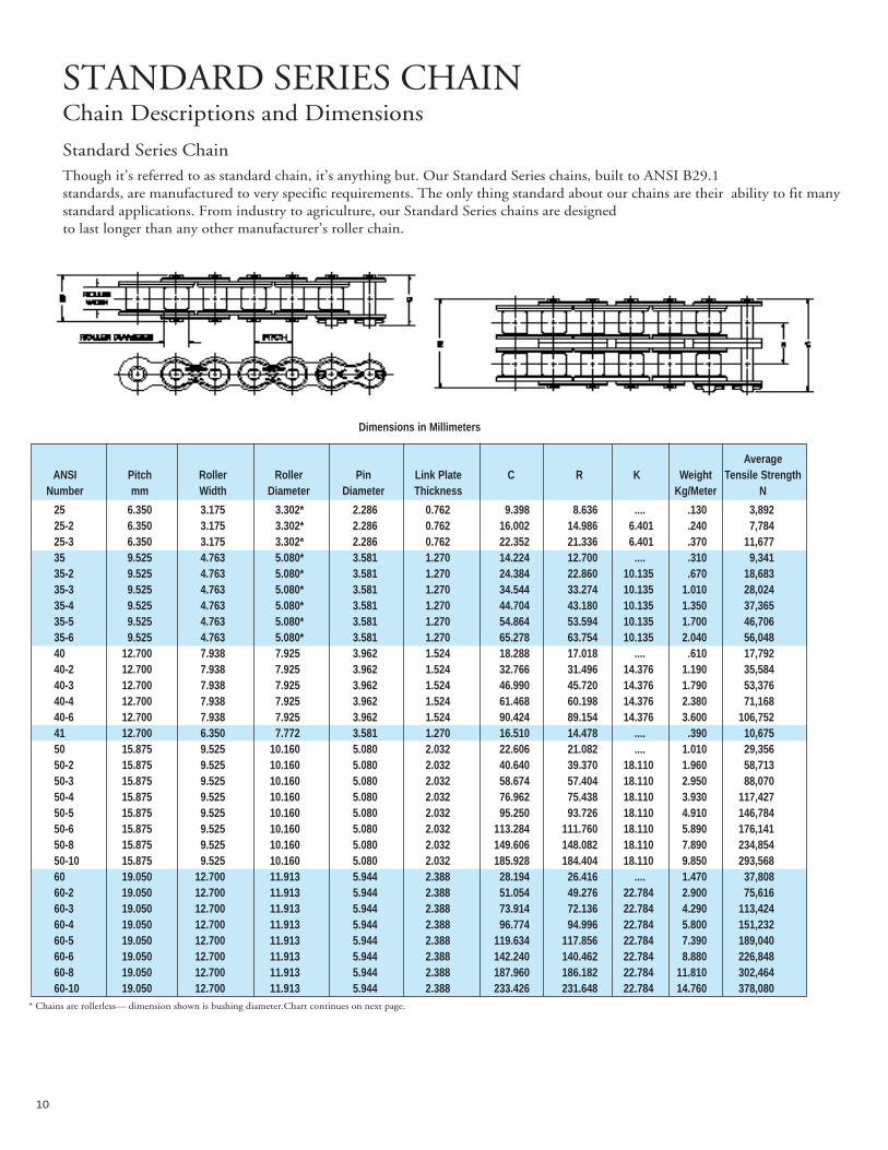
10
Dimensions in Millimeters
AverageANSI Pitch Roller Roller Pin Link Plate C R K Weight Tensile Strength
Number mm Width Diameter Diameter Thickness Kg/Meter N
25 6.350 3.175 3.302* 2.286 0.762 9.398 8.636 .... .130 3,89225-2 6.350 3.175 3.302* 2.286 0.762 16.002 14.986 6.401 .240 7,78425-3 6.350 3.175 3.302* 2.286 0.762 22.352 21.336 6.401 .370 11,67735 9.525 4.763 5.080* 3.581 1.270 14.224 12.700 .... .310 9,34135-2 9.525 4.763 5.080* 3.581 1.270 24.384 22.860 10.135 .670 18,68335-3 9.525 4.763 5.080* 3.581 1.270 34.544 33.274 10.135 1.010 28,02435-4 9.525 4.763 5.080* 3.581 1.270 44.704 43.180 10.135 1.350 37,36535-5 9.525 4.763 5.080* 3.581 1.270 54.864 53.594 10.135 1.700 46,70635-6 9.525 4.763 5.080* 3.581 1.270 65.278 63.754 10.135 2.040 56,04840 12.700 7.938 7.925 3.962 1.524 18.288 17.018 .... .610 17,79240-2 12.700 7.938 7.925 3.962 1.524 32.766 31.496 14.376 1.190 35,58440-3 12.700 7.938 7.925 3.962 1.524 46.990 45.720 14.376 1.790 53,37640-4 12.700 7.938 7.925 3.962 1.524 61.468 60.198 14.376 2.380 71,16840-6 12.700 7.938 7.925 3.962 1.524 90.424 89.154 14.376 3.600 106,75241 12.700 6.350 7.772 3.581 1.270 16.510 14.478 .... .390 10,67550 15.875 9.525 10.160 5.080 2.032 22.606 21.082 .... 1.010 29,35650-2 15.875 9.525 10.160 5.080 2.032 40.640 39.370 18.110 1.960 58,71350-3 15.875 9.525 10.160 5.080 2.032 58.674 57.404 18.110 2.950 88,07050-4 15.875 9.525 10.160 5.080 2.032 76.962 75.438 18.110 3.930 117,42750-5 15.875 9.525 10.160 5.080 2.032 95.250 93.726 18.110 4.910 146,78450-6 15.875 9.525 10.160 5.080 2.032 113.284 111.760 18.110 5.890 176,14150-8 15.875 9.525 10.160 5.080 2.032 149.606 148.082 18.110 7.890 234,85450-10 15.875 9.525 10.160 5.080 2.032 185.928 184.404 18.110 9.850 293,56860 19.050 12.700 11.913 5.944 2.388 28.194 26.416 .... 1.470 37,80860-2 19.050 12.700 11.913 5.944 2.388 51.054 49.276 22.784 2.900 75,61660-3 19.050 12.700 11.913 5.944 2.388 73.914 72.136 22.784 4.290 113,42460-4 19.050 12.700 11.913 5.944 2.388 96.774 94.996 22.784 5.800 151,23260-5 19.050 12.700 11.913 5.944 2.388 119.634 117.856 22.784 7.390 189,04060-6 19.050 12.700 11.913 5.944 2.388 142.240 140.462 22.784 8.880 226,84860-8 19.050 12.700 11.913 5.944 2.388 187.960 186.182 22.784 11.810 302,46460-10 19.050 12.700 11.913 5.944 2.388 233.426 231.648 22.784 14.760 378,080
* Chains are rollerless— dimension shown is bushing diameter.Chart continues on next page.
STANDARD SERIES CHAINChain Descriptions and Dimensions
Standard Series ChainThough it’s referred to as standard chain, it’s anything but. Our Standard Series chains, built to ANSI B29.1 standards, are manufactured to very specific requirements. The only thing standard about our chains are their ability to fit manystandard applications. From industry to agriculture, our Standard Series chains are designed to last longer than any other manufacturer’s roller chain.
11
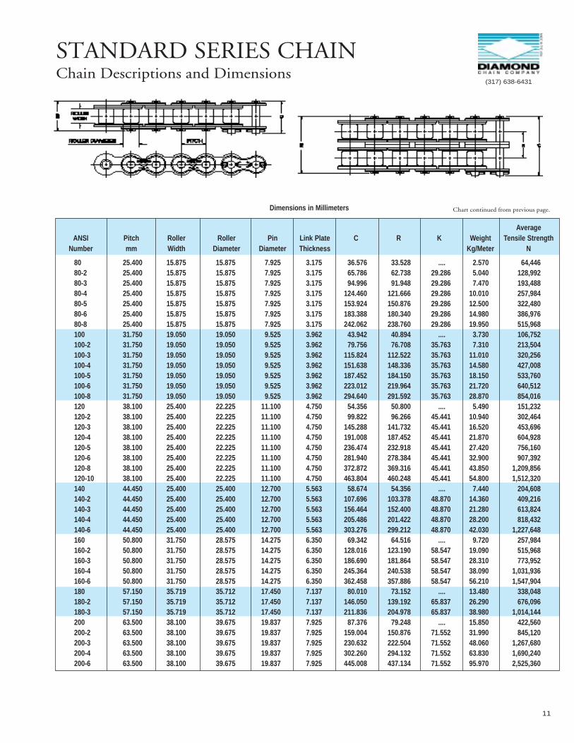
STANDARD SERIES CHAINChain Descriptions and Dimensions
Dimensions in Millimeters
AverageANSI Pitch Roller Roller Pin Link Plate C R K Weight Tensile Strength
Number mm Width Diameter Diameter Thickness Kg/Meter N
80 25.400 15.875 15.875 7.925 3.175 36.576 33.528 .... 2.570 64,44680-2 25.400 15.875 15.875 7.925 3.175 65.786 62.738 29.286 5.040 128,99280-3 25.400 15.875 15.875 7.925 3.175 94.996 91.948 29.286 7.470 193,48880-4 25.400 15.875 15.875 7.925 3.175 124.460 121.666 29.286 10.010 257,98480-5 25.400 15.875 15.875 7.925 3.175 153.924 150.876 29.286 12.500 322,48080-6 25.400 15.875 15.875 7.925 3.175 183.388 180.340 29.286 14.980 386,97680-8 25.400 15.875 15.875 7.925 3.175 242.062 238.760 29.286 19.950 515,968100 31.750 19.050 19.050 9.525 3.962 43.942 40.894 .... 3.730 106,752100-2 31.750 19.050 19.050 9.525 3.962 79.756 76.708 35.763 7.310 213,504100-3 31.750 19.050 19.050 9.525 3.962 115.824 112.522 35.763 11.010 320,256100-4 31.750 19.050 19.050 9.525 3.962 151.638 148.336 35.763 14.580 427,008100-5 31.750 19.050 19.050 9.525 3.962 187.452 184.150 35.763 18.150 533,760100-6 31.750 19.050 19.050 9.525 3.962 223.012 219.964 35.763 21.720 640,512100-8 31.750 19.050 19.050 9.525 3.962 294.640 291.592 35.763 28.870 854,016120 38.100 25.400 22.225 11.100 4.750 54.356 50.800 .... 5.490 151,232120-2 38.100 25.400 22.225 11.100 4.750 99.822 96.266 45.441 10.940 302,464120-3 38.100 25.400 22.225 11.100 4.750 145.288 141.732 45.441 16.520 453,696120-4 38.100 25.400 22.225 11.100 4.750 191.008 187.452 45.441 21.870 604,928120-5 38.100 25.400 22.225 11.100 4.750 236.474 232.918 45.441 27.420 756,160120-6 38.100 25.400 22.225 11.100 4.750 281.940 278.384 45.441 32.900 907,392120-8 38.100 25.400 22.225 11.100 4.750 372.872 369.316 45.441 43.850 1,209,856120-10 38.100 25.400 22.225 11.100 4.750 463.804 460.248 45.441 54.800 1,512,320140 44.450 25.400 25.400 12.700 5.563 58.674 54.356 .... 7.440 204,608140-2 44.450 25.400 25.400 12.700 5.563 107.696 103.378 48.870 14.360 409,216140-3 44.450 25.400 25.400 12.700 5.563 156.464 152.400 48.870 21.280 613,824140-4 44.450 25.400 25.400 12.700 5.563 205.486 201.422 48.870 28.200 818,432140-6 44.450 25.400 25.400 12.700 5.563 303.276 299.212 48.870 42.030 1,227,648160 50.800 31.750 28.575 14.275 6.350 69.342 64.516 .... 9.720 257,984160-2 50.800 31.750 28.575 14.275 6.350 128.016 123.190 58.547 19.090 515,968160-3 50.800 31.750 28.575 14.275 6.350 186.690 181.864 58.547 28.310 773,952160-4 50.800 31.750 28.575 14.275 6.350 245.364 240.538 58.547 38.090 1,031,936160-6 50.800 31.750 28.575 14.275 6.350 362.458 357.886 58.547 56.210 1,547,904180 57.150 35.719 35.712 17.450 7.137 80.010 73.152 .... 13.480 338,048180-2 57.150 35.719 35.712 17.450 7.137 146.050 139.192 65.837 26.290 676,096180-3 57.150 35.719 35.712 17.450 7.137 211.836 204.978 65.837 38.980 1,014,144200 63.500 38.100 39.675 19.837 7.925 87.376 79.248 .... 15.850 422,560200-2 63.500 38.100 39.675 19.837 7.925 159.004 150.876 71.552 31.990 845,120200-3 63.500 38.100 39.675 19.837 7.925 230.632 222.504 71.552 48.060 1,267,680200-4 63.500 38.100 39.675 19.837 7.925 302.260 294.132 71.552 63.830 1,690,240200-6 63.500 38.100 39.675 19.837 7.925 445.008 437.134 71.552 95.970 2,525,360
Chart continued from previous page.
(317) 638-6431
12
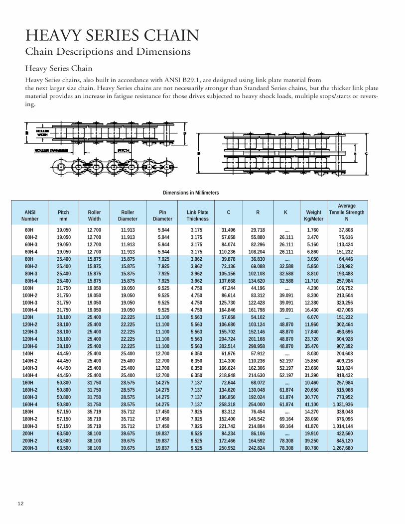
HEAVY SERIES CHAINChain Descriptions and Dimensions
Heavy Series ChainHeavy Series chains, also built in accordance with ANSI B29.1, are designed using link plate material from the next larger size chain. Heavy Series chains are not necessarily stronger than Standard Series chains, but the thicker link platematerial provides an increase in fatigue resistance for those drives subjected to heavy shock loads, multiple stops/starts or revers-ing.
Dimensions in Millimeters
AverageANSI Pitch Roller Roller Pin Link Plate C R K Weight Tensile Strength
Number mm Width Diameter Diameter Thickness Kg/Meter N
60H 19.050 12.700 11.913 5.944 3.175 31.496 29.718 .... 1.760 37,80860H-2 19.050 12.700 11.913 5.944 3.175 57.658 55.880 26.111 3.470 75,61660H-3 19.050 12.700 11.913 5.944 3.175 84.074 82.296 26.111 5.160 113,42460H-4 19.050 12.700 11.913 5.944 3.175 110.236 108.204 26.111 6.860 151,23280H 25.400 15.875 15.875 7.925 3.962 39.878 36.830 .... 3.050 64,44680H-2 25.400 15.875 15.875 7.925 3.962 72.136 69.088 32.588 5.850 128,99280H-3 25.400 15.875 15.875 7.925 3.962 105.156 102.108 32.588 8.810 193,48880H-4 25.400 15.875 15.875 7.925 3.962 137.668 134.620 32.588 11.710 257,984
100H 31.750 19.050 19.050 9.525 4.750 47.244 44.196 .... 4.200 106,752100H-2 31.750 19.050 19.050 9.525 4.750 86.614 83.312 39.091 8.300 213,504100H-3 31.750 19.050 19.050 9.525 4.750 125.730 122.428 39.091 12.380 320,256100H-4 31.750 19.050 19.050 9.525 4.750 164.846 161.798 39.091 16.430 427,008120H 38.100 25.400 22.225 11.100 5.563 57.658 54.102 .... 6.070 151,232120H-2 38.100 25.400 22.225 11.100 5.563 106.680 103.124 48.870 11.960 302,464120H-3 38.100 25.400 22.225 11.100 5.563 155.702 152.146 48.870 17.840 453,696120H-4 38.100 25.400 22.225 11.100 5.563 204.724 201.168 48.870 23.720 604,928120H-6 38.100 25.400 22.225 11.100 5.563 302.514 298.958 48.870 35.470 907,392140H 44.450 25.400 25.400 12.700 6.350 61.976 57.912 .... 8.030 204,608140H-2 44.450 25.400 25.400 12.700 6.350 114.300 110.236 52.197 15.850 409,216140H-3 44.450 25.400 25.400 12.700 6.350 166.624 162.306 52.197 23.660 613,824140H-4 44.450 25.400 25.400 12.700 6.350 218.948 214.630 52.197 31.390 818,432160H 50.800 31.750 28.575 14.275 7.137 72.644 68.072 .... 10.460 257,984160H-2 50.800 31.750 28.575 14.275 7.137 134.620 130.048 61.874 20.650 515,968160H-3 50.800 31.750 28.575 14.275 7.137 196.850 192.024 61.874 30.770 773,952160H-4 50.800 31.750 28.575 14.275 7.137 258.318 254.000 61.874 41.100 1,031,936180H 57.150 35.719 35.712 17.450 7.925 83.312 76.454 .... 14.270 338,048180H-2 57.150 35.719 35.712 17.450 7.925 152.400 145.542 69.164 28.060 676,096180H-3 57.150 35.719 35.712 17.450 7.925 221.742 214.884 69.164 41.870 1,014,144200H 63.500 38.100 39.675 19.837 9.525 94.234 86.106 .... 19.910 422,560200H-2 63.500 38.100 39.675 19.837 9.525 172.466 164.592 78.308 39.250 845,120200H-3 63.500 38.100 39.675 19.837 9.525 250.952 242.824 78.308 60.780 1,267,680
13
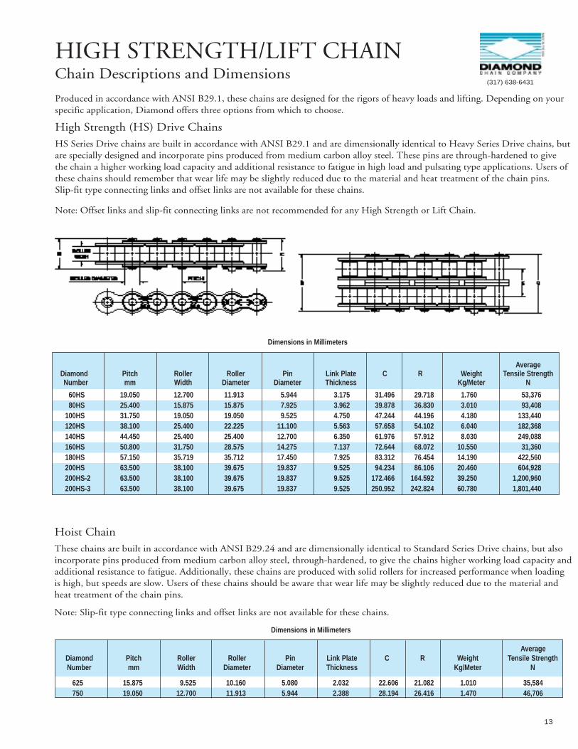
HIGH STRENGTH/LIFT CHAINChain Descriptions and Dimensions
Produced in accordance with ANSI B29.1, these chains are designed for the rigors of heavy loads and lifting. Depending on yourspecific application, Diamond offers three options from which to choose.
High Strength (HS) Drive ChainsHS Series Drive chains are built in accordance with ANSI B29.1 and are dimensionally identical to Heavy Series Drive chains, butare specially designed and incorporate pins produced from medium carbon alloy steel. These pins are through-hardened to givethe chain a higher working load capacity and additional resistance to fatigue in high load and pulsating type applications. Users ofthese chains should remember that wear life may be slightly reduced due to the material and heat treatment of the chain pins.Slip-fit type connecting links and offset links are not available for these chains.
Note: Offset links and slip-fit connecting links are not recommended for any High Strength or Lift Chain.
Dimensions in Millimeters
AverageDiamond Pitch Roller Roller Pin Link Plate C R Weight Tensile StrengthNumber mm Width Diameter Diameter Thickness Kg/Meter N
60HS 19.050 12.700 11.913 5.944 3.175 31.496 29.718 1.760 53,37680HS 25.400 15.875 15.875 7.925 3.962 39.878 36.830 3.010 93,408
100HS 31.750 19.050 19.050 9.525 4.750 47.244 44.196 4.180 133,440120HS 38.100 25.400 22.225 11.100 5.563 57.658 54.102 6.040 182,368140HS 44.450 25.400 25.400 12.700 6.350 61.976 57.912 8.030 249,088160HS 50.800 31.750 28.575 14.275 7.137 72.644 68.072 10.550 31,360180HS 57.150 35.719 35.712 17.450 7.925 83.312 76.454 14.190 422,560200HS 63.500 38.100 39.675 19.837 9.525 94.234 86.106 20.460 604,928200HS-2 63.500 38.100 39.675 19.837 9.525 172.466 164.592 39.250 1,200,960200HS-3 63.500 38.100 39.675 19.837 9.525 250.952 242.824 60.780 1,801,440
(317) 638-6431
Dimensions in Millimeters
AverageDiamond Pitch Roller Roller Pin Link Plate C R Weight Tensile StrengthNumber mm Width Diameter Diameter Thickness Kg/Meter N
625 15.875 9.525 10.160 5.080 2.032 22.606 21.082 1.010 35,584750 19.050 12.700 11.913 5.944 2.388 28.194 26.416 1.470 46,706
Hoist ChainThese chains are built in accordance with ANSI B29.24 and are dimensionally identical to Standard Series Drive chains, but alsoincorporate pins produced from medium carbon alloy steel, through-hardened, to give the chains higher working load capacity andadditional resistance to fatigue. Additionally, these chains are produced with solid rollers for increased performance when loadingis high, but speeds are slow. Users of these chains should be aware that wear life may be slightly reduced due to the material andheat treatment of the chain pins.
Note: Slip-fit type connecting links and offset links are not available for these chains.

14
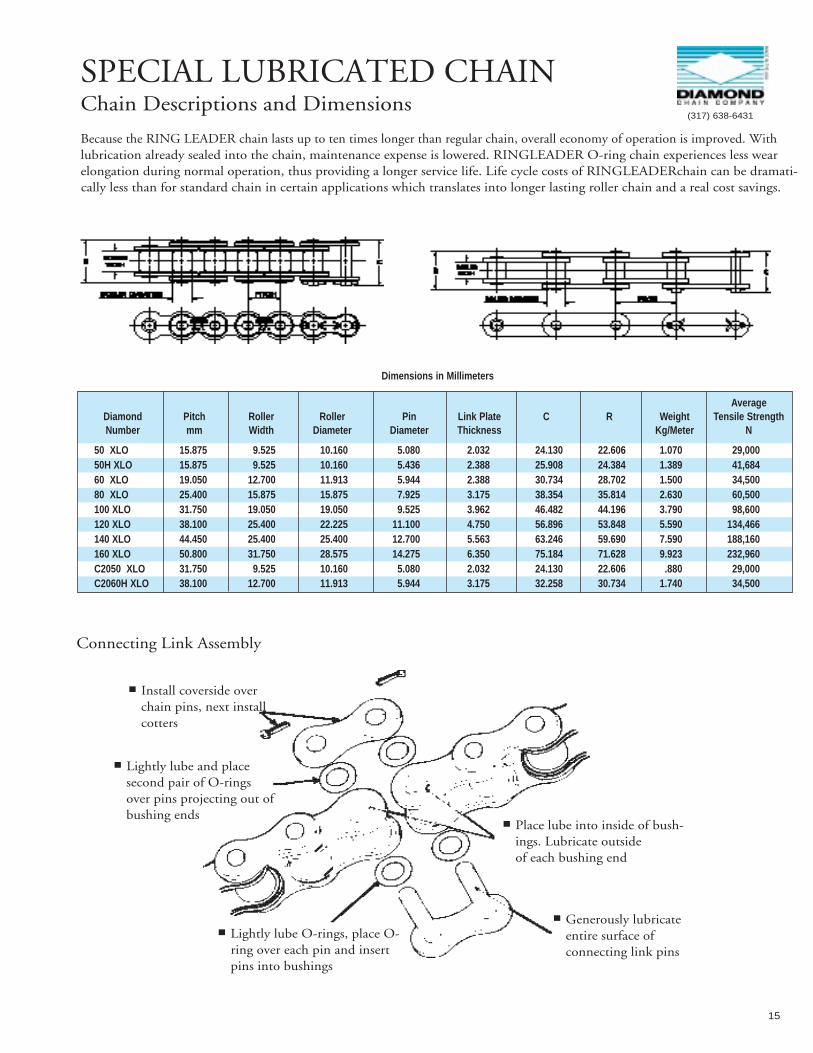
SPECIAL LUBRICATED CHAINChain Descriptions and Dimensions
RING LEADER®O-ring ChainDiamond’s RINGLEADERO-ring chain is specifically designed for applications that don’t permit regular lubrica-tion, requiring thechain to depend entirely upon initial factory lubrication throughout its service life. Depending upon the specific conditions, RINGLEADERcan provide up to ten times the wear life of standard chain.
Industries such as agriculture, food processing, packaging, printing, textile and chemical processing can introduce contaminants that damage standard chain. Dirt, mud, food particles, paper fines, dust and moisture can cause buildupon the chain and clog the openings on standard roller chain where lubrication enters the pin/bushing area. These contaminantscan even get inside the chain, actually damaging the surface of pins and bushings.
RINGLEADER O-ring chain is constructed with O-rings that seal a specially formulated lubricant into every joint. This sealed-inlubricant is essential for the chain’s optimum wear life and the O-rings also help to seal out and protect the internal surfaces from dirt, contaminants and moisture. Diamond recommends that RING LEADER O-ring chainreceive periodic external lubrication to maintain moisture on the external O-ring surfaces and to lubricate roller/sprocket contact surfaces. Note: Standard RINGLEADER O-ring chain can routinely operate in ambient tempera-tures up to 66° C. For higher temperature requirements, special O-rings can be substituted, allowing operation in temperatures of206° C or greater.
■ O-rings keep lubrication in and contaminants out.
■ Special bushings, having very uniform wall thickness, are precisely heat-treated to obtain an optimum balance of strength, wear resistance and toughness. The bushings are extended beyond the roller link plates. This feature helps theO-ring stay in position and provides maximum pin support, resulting in greater bearing area for the pin.
■ Pins are made from a special alloy steel and are hardened and centerless ground. Rigid quality standards ensure precise hardness control for high wear resistance and toughness.
15
SPECIAL LUBRICATED CHAINChain Descriptions and Dimensions
Because the RING LEADER chain lasts up to ten times longer than regular chain, overall economy of operation is improved. Withlubrication already sealed into the chain, maintenance expense is lowered. RINGLEADER O-ring chain experiences less wearelongation during normal operation, thus providing a longer service life. Life cycle costs of RINGLEADERchain can be dramati-cally less than for standard chain in certain applications which translates into longer lasting roller chain and a real cost savings.
Dimensions in Millimeters
AverageDiamond Pitch Roller Roller Pin Link Plate C R Weight Tensile StrengthNumber mm Width Diameter Diameter Thickness Kg/Meter N
50 XLO 15.875 9.525 10.160 5.080 2.032 24.130 22.606 1.070 29,00050H XLO 15.875 9.525 10.160 5.436 2.388 25.908 24.384 1.389 41,68460 XLO 19.050 12.700 11.913 5.944 2.388 30.734 28.702 1.500 34,50080 XLO 25.400 15.875 15.875 7.925 3.175 38.354 35.814 2.630 60,500100 XLO 31.750 19.050 19.050 9.525 3.962 46.482 44.196 3.790 98,600120 XLO 38.100 25.400 22.225 11.100 4.750 56.896 53.848 5.590 134,466140 XLO 44.450 25.400 25.400 12.700 5.563 63.246 59.690 7.590 188,160160 XLO 50.800 31.750 28.575 14.275 6.350 75.184 71.628 9.923 232,960C2050 XLO 31.750 9.525 10.160 5.080 2.032 24.130 22.606 .880 29,000C2060H XLO 38.100 12.700 11.913 5.944 3.175 32.258 30.734 1.740 34,500
■ Install coverside overchain pins, next installcotters
■ Lightly lube and placesecond pair of O-ringsover pins projecting out ofbushing ends
■ Lightly lube O-rings, place O-ring over each pin and insertpins into bushings
■ Generously lubricateentire surface of connecting link pins
■ Place lube into inside of bush-ings. Lubricate outside of each bushing end
(317) 638-6431
Connecting Link Assembly
16
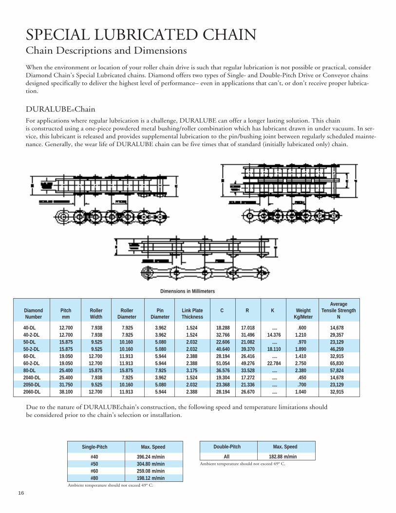
SPECIAL LUBRICATED CHAINChain Descriptions and Dimensions
When the environment or location of your roller chain drive is such that regular lubrication is not possible or practical, considerDiamond Chain’s Special Lubricated chains. Diamond offers two types of Single- and Double-Pitch Drive or Conveyor chainsdesigned specifically to deliver the highest level of performance– even in applications that can’t, or don’t receive proper lubrica-tion.
DURALUBE®ChainFor applications where regular lubrication is a challenge, DURALUBE can offer a longer lasting solution. This chain is constructed using a one-piece powdered metal bushing/roller combination which has lubricant drawn in under vacuum. In ser-vice, this lubricant is released and provides supplemental lubrication to the pin/bushing joint between regularly scheduled mainte-nance. Generally, the wear life of DURALUBE chain can be five times that of standard (initially lubricated only) chain.
Single-Pitch Max. Speed
#40 396.24 m/min#50 304.80 m/min#60 259.08 m/min#80 198.12 m/min
Ambient temperature should not exceed 49° C.
Double-Pitch Max. Speed
All 182.88 m/minAmbient temperature should not exceed 49° C.
Dimensions in Millimeters
AverageDiamond Pitch Roller Roller Pin Link Plate C R K Weight Tensile StrengthNumber mm Width Diameter Diameter Thickness Kg/Meter N
40-DL 12.700 7.938 7.925 3.962 1.524 18.288 17.018 .... .600 14,67840-2-DL 12.700 7.938 7.925 3.962 1.524 32.766 31.496 14.376 1.210 29,35750-DL 15.875 9.525 10.160 5.080 2.032 22.606 21.082 .... .970 23,12950-2-DL 15.875 9.525 10.160 5.080 2.032 40.640 39.370 18.110 1.890 46,25960-DL 19.050 12.700 11.913 5.944 2.388 28.194 26.416 .... 1.410 32,91560-2-DL 19.050 12.700 11.913 5.944 2.388 51.054 49.276 22.784 2.750 65,83080-DL 25.400 15.875 15.875 7.925 3.175 36.576 33.528 .... 2.380 57,8242040-DL 25.400 7.938 7.925 3.962 1.524 19.304 17.272 .... .450 14,6782050-DL 31.750 9.525 10.160 5.080 2.032 23.368 21.336 .... .700 23,1292060-DL 38.100 12.700 11.913 5.944 2.388 28.194 26.670 .... 1.040 32,915
Due to the nature of DURALUBEchain’s construction, the following speed and temperature limitations should be considered prior to the chain’s selection or installation.

17
CORROSION/MOISTURE RESISTANT CHAINChain Descriptions and Dimensions
Nickel-Plated ChainDiamond Chain produces a full line of Nickel-Plated roller chains for a variety of uses in environments where the chains areexposed to moisture. Common uses include applications exposed to the weather, high humidity or those on machines that are fre-quently washed down with water.
Diamond Nickel-Plated chain is different from many rust-resistant chains, because Diamond electroless nickel plates all of thecomponents before assembly, virtually eliminating the possibility of stress-corrosion cracking. Pre-assembly plating also ensures all components are plated, which prevents internal rust from seeping out and causing contami-nation.
Note: These chains are not intended to resist corrosion from caustic chemicals or acids. For those types of applications, stainless steel chain is recommended.
Dimensions in Millimeters
AverageDiamond Pitch Roller Roller Pin Link Plate C R Weight Tensile StrengthNumber mm Width Diameter Diameter Thickness Kg/Meter N
25NP 6.350 3.175 3.302* 2.286 .762 9.398 8.636 .130 3,89235NP 9.525 4.763 5.080* 3.581 1.270 14.224 12.700 .330 9,34140NP 12.700 7.938 7.925 3.962 1.524 18.288 17.018 .620 17,79250NP 15.875 9.525 10.160 5.080 2.032 22.606 21.082 1.010 29,35660NP 19.050 12.700 11.913 5.944 2.388 28.194 26.416 1.440 37,80880NP 25.400 15.875 15.875 7.925 3.175 36.576 33.528 2.530 64,446100NP 31.750 19.050 19.050 9.525 3.962 43.942 40.894 3.720 106,752120NP 38.100 25.400 22.225 11.100 4.750 54.356 50.800 5.510 151,232C2040NP 25.400 7.938 7.925 3.962 1.524 19.304 17.272 .480 16,458C2050NP 31.750 9.525 10.160 5.080 2.032 23.368 21.336 .820 27,133C2060HNP 38.100 12.700 11.913 5.944 3.175 31.750 29.972 1.440 37,808
* Chains are rollerless — dimension shown is bushing diameter.
(317) 638-6431
18
CORROSION/MOISTURE RESISTANT CHAINChain Descriptions and Dimensions
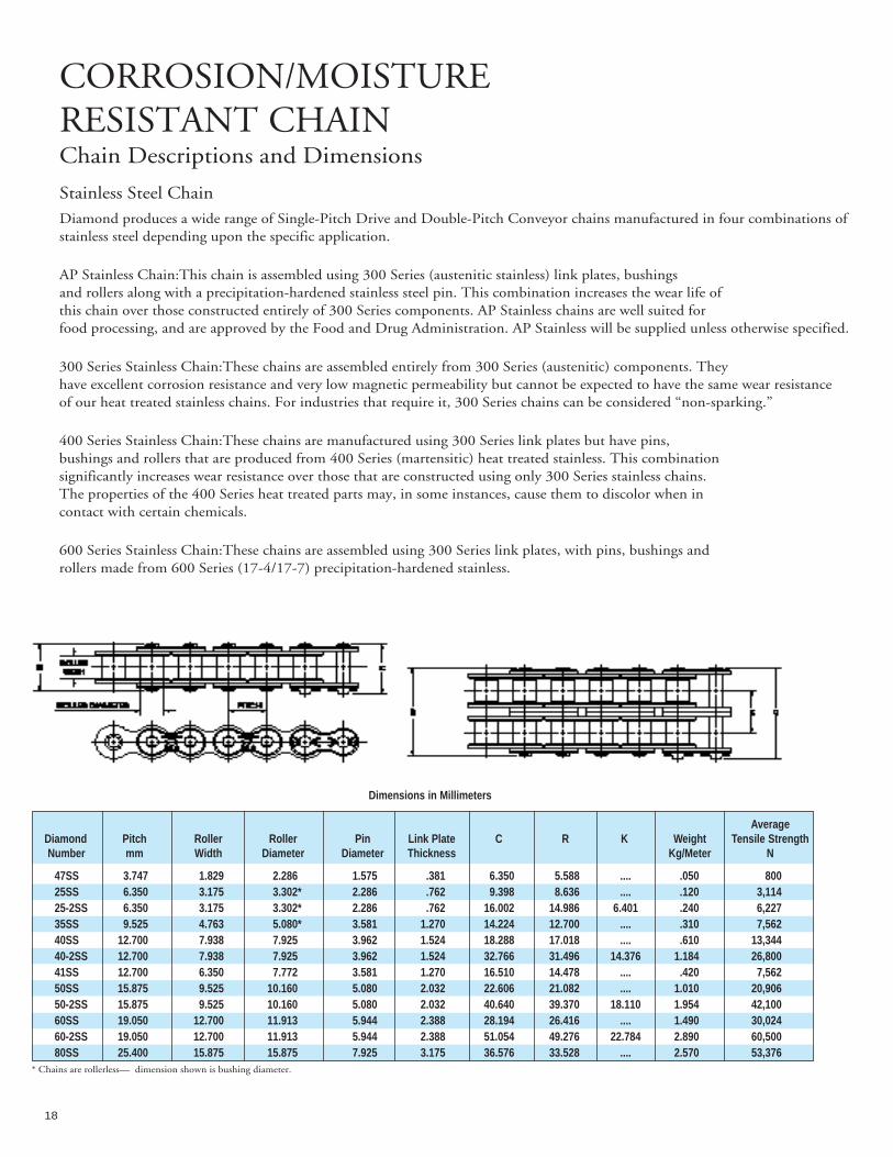
Stainless Steel Chain
Diamond produces a wide range of Single-Pitch Drive and Double-Pitch Conveyor chains manufactured in four combinations ofstainless steel depending upon the specific application.
AP Stainless Chain:This chain is assembled using 300 Series (austenitic stainless) link plates, bushings and rollers along with a precipitation-hardened stainless steel pin. This combination increases the wear life of this chain over those constructed entirely of 300 Series components. AP Stainless chains are well suited for food processing, and are approved by the Food and Drug Administration. AP Stainless will be supplied unless otherwise specified.
300 Series Stainless Chain:These chains are assembled entirely from 300 Series (austenitic) components. Theyhave excellent corrosion resistance and very low magnetic permeability but cannot be expected to have the same wear resistanceof our heat treated stainless chains. For industries that require it, 300 Series chains can be considered “non-sparking.”
400 Series Stainless Chain:These chains are manufactured using 300 Series link plates but have pins, bushings and rollers that are produced from 400 Series (martensitic) heat treated stainless. This combination significantly increases wear resistance over those that are constructed using only 300 Series stainless chains. The properties of the 400 Series heat treated parts may, in some instances, cause them to discolor when in contact with certain chemicals.
600 Series Stainless Chain:These chains are assembled using 300 Series link plates, with pins, bushings androllers made from 600 Series (17-4/17-7) precipitation-hardened stainless.
Dimensions in Millimeters
AverageDiamond Pitch Roller Roller Pin Link Plate C R K Weight Tensile StrengthNumber mm Width Diameter Diameter Thickness Kg/Meter N
47SS 3.747 1.829 2.286 1.575 .381 6.350 5.588 .... .050 80025SS 6.350 3.175 3.302* 2.286 .762 9.398 8.636 .... .120 3,11425-2SS 6.350 3.175 3.302* 2.286 .762 16.002 14.986 6.401 .240 6,22735SS 9.525 4.763 5.080* 3.581 1.270 14.224 12.700 .... .310 7,56240SS 12.700 7.938 7.925 3.962 1.524 18.288 17.018 .... .610 13,34440-2SS 12.700 7.938 7.925 3.962 1.524 32.766 31.496 14.376 1.184 26,80041SS 12.700 6.350 7.772 3.581 1.270 16.510 14.478 .... .420 7,56250SS 15.875 9.525 10.160 5.080 2.032 22.606 21.082 .... 1.010 20,90650-2SS 15.875 9.525 10.160 5.080 2.032 40.640 39.370 18.110 1.954 42,10060SS 19.050 12.700 11.913 5.944 2.388 28.194 26.416 .... 1.490 30,02460-2SS 19.050 12.700 11.913 5.944 2.388 51.054 49.276 22.784 2.890 60,50080SS 25.400 15.875 15.875 7.925 3.175 36.576 33.528 .... 2.570 53,376
* Chains are rollerless— dimension shown is bushing diameter.
19
(317) 638-6431
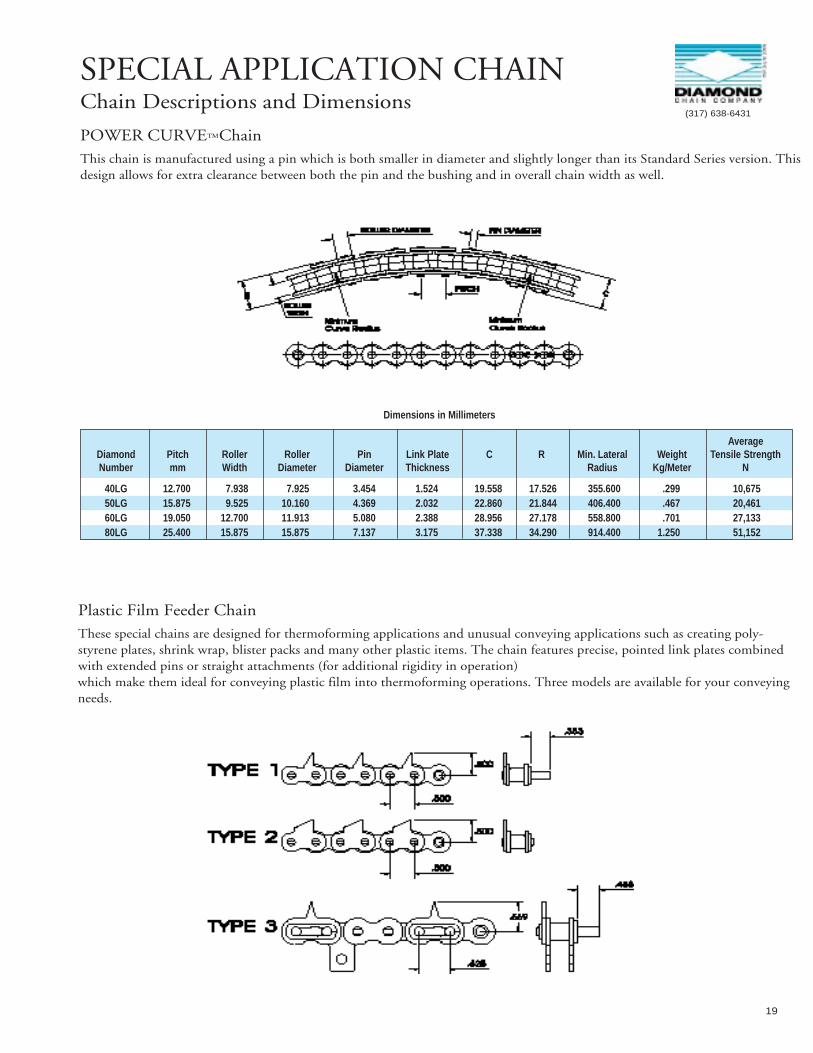
SPECIAL APPLICATION CHAINChain Descriptions and Dimensions
POWER CURVE™ChainThis chain is manufactured using a pin which is both smaller in diameter and slightly longer than its Standard Series version. Thisdesign allows for extra clearance between both the pin and the bushing and in overall chain width as well.
Dimensions in Millimeters
AverageDiamond Pitch Roller Roller Pin Link Plate C R Min. Lateral Weight Tensile StrengthNumber mm Width Diameter Diameter Thickness Radius Kg/Meter N
40LG 12.700 7.938 7.925 3.454 1.524 19.558 17.526 355.600 .299 10,67550LG 15.875 9.525 10.160 4.369 2.032 22.860 21.844 406.400 .467 20,46160LG 19.050 12.700 11.913 5.080 2.388 28.956 27.178 558.800 .701 27,13380LG 25.400 15.875 15.875 7.137 3.175 37.338 34.290 914.400 1.250 51,152
Plastic Film Feeder ChainThese special chains are designed for thermoforming applications and unusual conveying applications such as creating poly-styrene plates, shrink wrap, blister packs and many other plastic items. The chain features precise, pointed link plates combinedwith extended pins or straight attachments (for additional rigidity in operation) which make them ideal for conveying plastic film into thermoforming operations. Three models are available for your conveyingneeds.
20
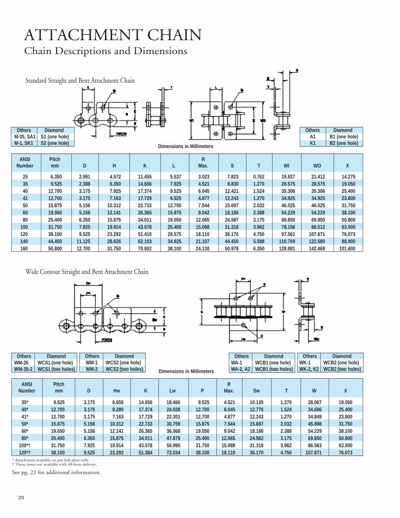
ATTACHMENT CHAINChain Descriptions and Dimensions
Dimensions in Millimeters
ANSI Pitch RNumber mm D Hw K Lw P Max. Sw T W X
35* 9.525 3.175 6.655 14.656 18.466 9.525 4.521 10.135 1.270 28.067 19.05040* 12.700 3.175 8.280 17.374 24.028 12.700 6.045 12.776 1.524 34.696 25.40041* 12.700 3.175 7.163 17.729 22.301 12.700 4.877 12.243 1.270 34.849 23.80050* 15.875 5.156 10.312 22.733 30.759 15.875 7.544 15.697 2.032 45.898 31.75060* 19.050 5.156 12.141 26.365 36.068 19.050 9.042 18.186 2.388 54.229 38.10080* 25.400 6.350 15.875 34.011 47.879 25.400 12.065 24.562 3.175 69.850 50.800
100*† 31.750 7.925 19.914 43.078 59.995 31.750 15.088 31.318 3.962 86.563 63.500120*† 38.100 9.525 23.292 51.384 72.034 38.100 18.110 36.170 4.750 107.671 76.073
Standard Straight and Bent Attachment Chain
Dimensions in Millimeters
ANSI Pitch RNumber mm D H K L Max. S T WI WO X
25 6.350 2.591 4.572 11.455 5.537 3.023 7.823 0.762 19.837 21.412 14.27535 9.525 2.388 6.350 14.656 7.925 4.521 9.830 1.270 28.575 28.575 19.05040 12.700 3.175 7.925 17.374 9.525 6.045 12.421 1.524 35.306 35.306 25.40041 12.700 3.175 7.163 17.729 9.525 4.877 12.243 1.270 34.925 34.925 23.80050 15.875 5.156 10.312 22.733 12.700 7.544 15.697 2.032 46.025 46.025 31.75060 19.050 5.156 12.141 26.365 15.875 9.042 18.186 2.388 54.229 54.229 38.10080 25.400 6.350 15.875 34.011 19.050 12.065 24.587 3.175 69.850 69.850 50.800
100 31.750 7.925 19.914 43.078 25.400 15.088 31.318 3.962 78.156 86.512 63.500120 38.100 9.525 23.292 51.410 28.575 18.110 36.170 4.750 97.561 107.671 76.073140 44.450 11.125 28.626 62.103 34.925 21.107 44.450 5.588 110.769 122.580 88.900160 50.800 12.700 31.750 70.002 38.100 24.130 50.978 6.350 128.981 142.469 101.600
Wide Contour Straight and Bent Attachment Chain
* Attachment available on pin link plate only.† These items not available with 48-hour delivery.
Others DiamondM-35, SA1 S1 (one hole)M-1, SK1 S2 (one hole)
Others DiamondA1 B1 (one hole)K1 B2 (one hole)
Others DiamondWM-35 WCS1 (one hole)WM-35-2 WCS1 (two holes)
Others DiamondWM-1 WCS2 (one hole)WM-2 WCS2 (two holes)
Others DiamondWA-1 WCB1 (one hole)WA-2, A2 WCB1 (two holes)
Others DiamondWK-1 WCB2 (one hole)WK-2, K2 WCB2 (two holes)
See pg. 22 for additional information.

21
ATTACHMENT CHAINChain Descriptions and Dimensions
Dimensions in Millimeters
With OneStandard Roller With Two* Attachment Holes Attachment Hole Large Roller
ANSI Roller Pitch ANSI RollerNumber Diam. mm B D S K L T D1 S1 Number Diam.
C2040* 7.925 25.400 9.525 3.175 13.487 19.634 19.050 1.524 4.775 11.125 C-2042 15.875C2050* 10.160 31.750 11.913 5.156 15.875 24.663 23.800 2.032 6.350 14.300 C-2052 19.050C2060H* 11.913 38.100 14.275 5.156 19.050 30.556 28.575 3.175 8.357 17.475 C-2062H 22.225C2080H* 15.875 50.800 19.050 6.756 25.400 40.386 38.100 3.962 9.525 22.225 C-2082H 28.575C2100H* 19.050 63.500 23.800 8.331 31.750 50.343 47.625 4.750 13.106 28.575 C-2102H 39.675C2120H* 22.225 76.200 28.575 9.931 37.313 60.122 57.150 5.563 14.300 33.325 C-2122H 44.450C2160H* 28.575 101.600 38.100 13.106 50.800 78.486 76.200 7.137 19.050 44.450 C-2162H 57.150
Dimensions in Millimeters
Standard RollerPitch Large RollerANSI Number Roller Diam. mm A B D H L T WI WO X ANSI Number Roller Diam.
C2040* 7.925 25.400 12.700 9.525 3.175 9.119 19.050 1.524 34.290 37.668 25.400 C-2042 15.875C2050* 10.160 31.750 15.875 11.913 5.156 11.506 23.800 2.032 42.977 47.320 31.750 C-2052 19.050C2060H* 11.913 38.100 21.438 14.275 5.156 14.681 28.575 3.175 55.143 62.128 42.875 C-2062H 22.225C2080H* 15.875 50.800 27.788 19.050 6.756 19.456 38.100 3.962 70.917 79.375 55.575 C-2082H 28.575C2100H* 19.050 63.500 33.325 23.800 8.331 23.419 47.625 4.750 90.272 100.355 66.675 C-2102H 39.675C2120H* 22.225 76.200 39.675 28.575 9.931 27.813 57.150 5.563 109.677 121.463 79.375 C-2122H 44.450C2160H* 28.575 101.600 52.400 38.100 13.106 36.525 76.200 7.137 140.208 155.346 104.775 C-2162H 57.150
Double-Pitch Bent AttachmentsOval Contour Link PlatesStandard and Oversized Roller
Double-Pitch Straight AttachmentsOval Contour Link PlatesStandard and Oversized Roller
*Two attachment holes stock.One attachment hole made-to-order.
Others DiamondA1 B1 (one hole)A2 B1 (two holes)
Others DiamondK1 B2 (one hole)K2 B2 (two holes)
Others DiamondM-1, SK1 S2 (one hole)M-2, SK2 S2 (two holes)
Others DiamondM-35, SA1 S1 (one hole)M-35-2, SA2 S1 (two holes)
*Two attachment holes stock.One attachment hole made-to-order.
See pg. 22 for additional information.
(317) 638-6431

22
EXTENDED PIN CHAINChain Descriptions and Dimensions
Standard Extended PinsFor ANSI Standard Series Chains andDouble-Pit ch Conveyor Chains
Dimensions in Millimeters
Others DiamondD1 E1 (one extended pin)D3 E2 (two extended pins)
ANSI Pitch ANSI Pitch ANSI PitchNumber mm D±.013mm L ± .254mm Number mm D ± .013mm L ± .254mm Number mm D ±.013mm L ± .254mm
35 9.525 3.581 9.525 80 25.400 7.925 19.050 C-2040, C-2042 25.400 3.962 9.52540 12.700 3.962 9.728 100 31.750 9.525 23.800 C-2050, C-2052 31.750 5.080 11.88741 12.700 3.581 9.525 120 38.100 11.100 28.575 C-2060H, C-2062H 38.100 5.944 14.27550 15.875 5.080 11.887 140 44.450 12.700 33.325 C-2080H, C-2082H 50.800 7.925 19.05060 19.050 5.944 14.275 160 50.800 14.275 38.100 C-2100H, C-2102H 63.500 9.525 23.800
Dimensions in Millimeters
Chain Hole Screw ScrewSize Diameter Size Diameter
25 2.590 M2.5 2.50035 2.390 M2 2.00040 3.180 M3 3.00041 3.180 M3 3.00050 5.160 M5 5.00060 5.160 M5 5.00080 6.350 M6 6.000100 7.930 M6 6.000120 9.530 M8 8.000140 11.130 M10 10.000160 12.700 M12 12.000
Dimensions in Millimeters
Chain Hole Screw ScrewSize Diameter* Size Diameter
C2040 3.180 M3 3.000C2050 5.160 M5 5.000C2060H 5.160 M5 5.000C2080H 6.760 M6 6.000C2100H 8.330 M8 8.000C2120H 9.930 M8 8.000C2160H 13.110 M12 12.000
*Straight, one hole attachments have larger diameters than shown. Refer to Double- PitchStraight and Bent Attachment tables for more detail.
Attachment Hole SizesDiamond’s attachment hole sizes are sometimes unique. Diamond has such a long history of producing roller chain that many ofour attachments were designed long before any standardization was adopted throughout the industry. We continue to produce our most common attachments with holes to accommodate the following screw sizes:
If your application requires a different attachment hole than shown in this section, please contact Diamond as many alternate lugholes are available. Many can be shipped from stock.
23
(317) 638-6431
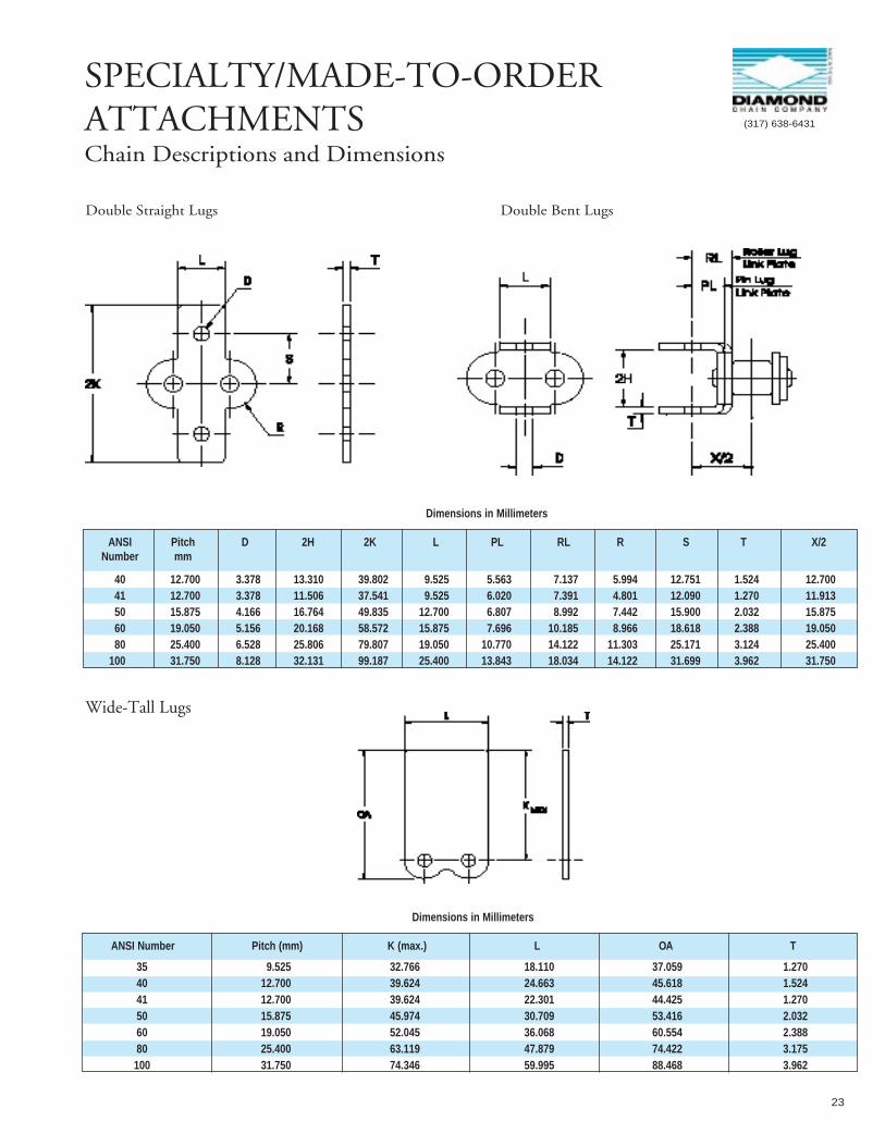
SPECIALTY/MADE-TO-ORDER ATTACHMENTSChain Descriptions and Dimensions
Double Straight Lugs Double Bent Lugs
Dimensions in Millimeters
ANSI Number Pitch (mm) K (max.) L OA T
35 9.525 32.766 18.110 37.059 1.27040 12.700 39.624 24.663 45.618 1.52441 12.700 39.624 22.301 44.425 1.27050 15.875 45.974 30.709 53.416 2.03260 19.050 52.045 36.068 60.554 2.38880 25.400 63.119 47.879 74.422 3.175
100 31.750 74.346 59.995 88.468 3.962
Wide-Tall Lugs
Dimensions in Millimeters
ANSI Pitch D 2H 2K L PL RL R S T X/2Number mm
40 12.700 3.378 13.310 39.802 9.525 5.563 7.137 5.994 12.751 1.524 12.70041 12.700 3.378 11.506 37.541 9.525 6.020 7.391 4.801 12.090 1.270 11.91350 15.875 4.166 16.764 49.835 12.700 6.807 8.992 7.442 15.900 2.032 15.87560 19.050 5.156 20.168 58.572 15.875 7.696 10.185 8.966 18.618 2.388 19.05080 25.400 6.528 25.806 79.807 19.050 10.770 14.122 11.303 25.171 3.124 25.400
100 31.750 8.128 32.131 99.187 25.400 13.843 18.034 14.122 31.699 3.962 31.750

24
ATTACHMENT CHAIN CONSIDERATIONSChain Descriptions and Dimensions
Assembly:While it is possible to purchase base chain or attachment components and construct an attachment chain, it isstrongly recommended that chains be ordered and assembled at the factory to ensure the proper fit and alignment of all partsalong with any length or matching requirements.
Manufacturing Length Tolerance:ANSI defines the permissible length of an assembled section of roller chain. The allowable length tolerances vary from model to model and are also affected by the chain’s construction, i.e., with or without attachments.
As an example, the assembled length tolerance for an ANSI one inch pitch chain (#80) is + 1.33mm/-.000mm per meter. When attachments are added to the chain’s design, the tolerance for length expands to + 2.66mm/-.000mm per meter. This means that a section of #80 chain 12 pitches long (304.8mm nominal) can measure as long as305.206mm but no less than 304.8mm. The same section of chain assembled with bent, straight, or extended pin attachmentscould measure as long as 305.6mm but again, no less than 304.8mm.
In common practice, manufacturers strive to produce chain nearer to the nominal figure, but the maximum allowable length toler-ance should always be considered when designing for take-ups and catenary chain sag. If the application requires it, some designand assembly steps can be taken to direct the length of the chain toward the nominal. However, on a routine basis machinedesigns based on a nominal or specified chain length should be avoided.
Length Matching of Roller Chains:Many applications require two or more chains, normally with attachments, torun in parallel with “flights” joining the chains together forming a conveyor or transfer type system. In these cases it is critical tohave the chains ordered as a set, matched for length and installed on the machinery with the same relationship to one another aswhen they were manufactured.
Diamond offers two degrees of matching for parallel operation:Class I and Class II
Class I -A Class I match assures that the longest and the shortest chain in a given set will not vary in overall length by morethan .500mm/m. Again using #80 chain as an example, the length of two #80 chains 120 pitches long will not vary by more than1.524mm in overall length (3.048m x .500mm/m = 1.524mm). The shortest could measure 3048mm + .000mm (remember, no negative tolerance) and the longest could measure up to 3048mm + 1.524mmand satisfy the Class I requirement. Class I matching is most often accomplished by assembling the chains from selected lots ofcomponent parts.
Class II -A Class II match is much more stringent and assures that the longest and the shortest chain in a given set will notvary in overall length by more than .167mm/m. Applying this new tolerance to the above example, the length of two #80 chains 120 pitches long will not vary by more than .508mm in overall length (3.048m x .167mm/m =.508mm). The shortest could measure 3048mm + .000mm and the longest could measure 3048mm + .508mm and satisfy therequirement. Class II matching is quite difficult and requires some very unique procedures.
Differences -It is important to remember that matched chains still fall under the overall length limitations imposed by eitherANSI or the manufacturer. Matching does notassure the user of chains with a finite overall length, only that the chains in theset have a controlled relationship to one another.

25
(317) 638-6431
BRITISH STANDARD ROLLER CHAINDiamond British Standard roller chains conform to the specifications of IS 2403-1975, ISO R606 “B”, DIN 8187 and BS 228, andare supplied in single and multiple strand.
04B 1 6.000 2.500 4.000 1.850 5.000 10.300 7.400 .... .120 3,000
05B-14 1 8.000 3.000 5.000 2.310 7.100 11.700 8.600 .... .100 5,000
06B-1 1 9.530 5.720 6.350 3.280 8.260 16.780 13.490 .... .450 8,94006B-2 2 9.530 5.720 6.350 3.280 8.260 27.100 23.790 10.240 .800 16,94606B-3 3 9.530 5.720 6.350 3.280 8.260 37.310 34.010 10.240 1.180 24,908
08B-13 1 12.700 7.750 8.510 4.450 11.800 20.900 16.900 .... .740 17,83608B-2 2 12.700 7.750 8.510 4.450 11.800 34.900 30.900 14.800 1.410 31,18008B-3 3 12.700 7.750 8.510 4.450 11.800 47.800 44.900 14.800 2.080 44,524
D0801 1 12.700 3.300 7.750 3.640 9.910 11.700 10.200 .... .280 8,000D0811 1 12.700 4.880 7.750 3.640 9.910 13.100 11.700 .... .380 8,000
10B-13 1 15.900 9.650 10.200 5.080 14.700 23.700 19.600 .... .950 22,24010B-2 2 15.900 9.650 10.200 5.080 14.700 40.310 36.190 16.600 1.870 44,52410B-3 3 15.900 9.650 10.200 5.080 14.700 56.890 52.810 16.600 2.800 66,764
12B-13 1 19.100 11.700 12.100 5.720 16.100 27.310 22.710 .... 1.190 28,91212B-23 2 19.100 11.700 12.100 5.720 16.100 46.810 42.190 19.500 2.340 57,86812B-3 3 19.100 11.700 12.100 5.720 16.100 66.290 61.690 19.500 3.470 86,780
16B-13 1 25.400 17.000 15.900 8.280 21.100 38.890 33.500 .... 2.720 56,88916B-2 2 25.400 17.000 15.900 8.280 21.100 73.410 67.990 31.880 5.370 113,73516B-3 3 25.400 17.000 15.900 8.280 21.100 105.300 99.890 31.880 8.020 170,625
20B-1 1 31.800 19.600 19.100 10.200 26.420 49.300 43.210 .... 3.880 93,14120B-2 2 31.800 19.600 19.100 10.200 26.420 85.800 79.710 36.450 7.660 176,49620B-3 3 31.800 19.600 19.100 10.200 26.420 122.200 116.100 36.450 11.440 264,744
24B-1 1 38.100 25.400 25.400 14.600 33.400 59.990 53.390 .... 7.070 166,71124B-2 2 38.100 25.400 25.400 14.600 33.400 108.400 101.800 48.360 13.870 317,721 24B-3 3 38.100 25.400 25.400 14.600 33.400 156.800 150.200 48.360 20.890 475,580
28B-1 1 44.450 30.990 27.940 15.900 42.240 65.100 72.500 .... 9.420 168,71228B-2 2 44.450 30.990 27.940 15.900 42.240 124.700 132.100 59.560 18.730 337,42428B-3 3 44.450 30.990 27.940 15.900 42.240 184.300 191.700 59.560 28.040 506,136
32B-1 1 50.800 30.990 39.370 17.800 48.260 67.400 75.400 .... 10.370 211,94832B-2 2 50.800 30.990 39.370 17.800 48.260 126.000 133.900 58.550 20.620 443,89632B-3 3 50.800 30.990 39.370 17.800 48.260 184.500 192.400 58.550 30.870 665,845
40B-12 1 63.500 38.100 39.370 22.890 60.300 79.220 87.270 .... 16.880 352,29940B-22 2 63.500 38.100 38.370 22.890 60.300 151.210 159.560 72.290 32.970 704,59840B-32 3 63.500 38.100 39.370 22.890 60.300 223.800 231.850 72.290 50.040 1,056,897
48B-12 1 76.200 45.720 48.260 29.240 64.000 98.880 107.780 .... 23.920 548,02048B-22 2 76.200 45.720 48.260 29.240 64.000 190.090 199.090 91.210 47.500 1,096,04148B-32 3 76.200 45.720 48.260 29.240 64.000 281.300 290.190 91.210 71.070 1,764,164
British Standard Chain Manufactured for Diamond Chain to Diamond Specifications.
1.Non ISO/DIN/B.S. Standard2. Factory Order Only
3. Available with straight side plates from Almere stock4. For reference only
MinimumISO/DIN Tensile
BS No. of Pitch Roller Roller Pin Weight StrengthNumber Strands mm Width Diam. Diam. H (max.) C (max.) R (max.) (K) Kg/Meter N
Dimensions in Millimeters

26
CHAIN TOOLSTool Descriptions and Dimensions
Chain Connecting Tool
A tool designed to make roller chain connection quick and easy.
To use:
1. Hook the jaws into each end of the chain.
2. Turn the screw to pull the ends of the chain close together.
3 Install the correcting link nect
Roller Chain Pin Extractor A tool designed to disassemble press fit pins from roller chain.
To use:
1. Grind off pin head
2 Attach tool to chain with jaws inside roller link plates and over roller
3 Turn screw to press out pin
Approx. Shipping For Chain Sizes Model Number Wt. (Kg)
35 - 60 CT 35 .13680 - 240 CT 80 .907
For Chain Model Approx. Shipping Sizes Number Description Wt. (Kg)
25 - 60 PE 113 Chain Pin Extractor .363PE 113 - 103 Replacement Tip Assembly .045PE 113 - 108 Replacement Tip .005
80 - 100 PE 135 Chain Pin Extractor 1.270PE 135 - 108 Replacement Tip .005

������
����� ������������������ �� �
���� ���
��������������� ����
����������������������������� ��� �
��������������� �!��� ����
"������� ������������������ �#��
����$� � �
�%��&%"�� '(��
��)� ������ '���
�� �� ���� ��� '*� �
������ '*��
���+��������� ',��
�������-����-������ '.� �
�/0����%�1�� '.��
���2�&������/3��� � '���
�������� ����� '�� �
������ ������ '���
��������4������� #$�.��
���������������� �� �
�����5����� �(��
���4�)�������)� *��
��������� �&��+������6�)� '#� �
�%��&%"������� '(��
�7���������������� ����
��)� ����������� '�� �
�� �� ���� �������� '*��
������ '*��
� /.��'� �� �
8�9���9��� ��������� #��
���+��3����������� ',��
�������-����-����������� .� �
�/0����%�1�� '.��
���2�&������/3��� ������ '���
4������):8��35�3/����� �*� �
�������� ���������� '���
������ ����������� '���
5����� �(� �
� � �
�
��
�
������������������������9������4���9���������� ���������9���"������� ��������������������$� 4������)������$�� ���9��9��$�-���5�4$� 44�������� 44�������9�;�


![Koen Deldaele - pmg.pmgroup.bepmg.pmgroup.be/enews/buildup/pdfhoutbouw/6Knauf_pitch.pdf · 2.DIAMOND BOARD [ONE] Gipsplaat Overeenkomstig EN 520 Diamond Board = DFH2IR Diamond Board](https://img.pdfslide.tips/doc/110x75/5f7b8965b583b24bed367e93/koen-deldaele-pmg-2diamond-board-one-gipsplaat-overeenkomstig-en-520-diamond.jpg)