Embed Size (px)
DESCRIPTION
Standart operating procedures for a320donbassaero
Citation preview
OPERATIONAL MANUAL PART A
РУКОВОДСТВО ПО ЭКСПЛУАТАЦИИ ЧАСТЬ А
Стандартные операционные процедуры А-318/319/320/321
REV 44 JUN 2010
ООО “АK ”Донбасcаэро” Часть A Стр 1
0. CONTENTS
0. CONTENTS ………………….……………………………………………………………....1
1. GENERAL INFORMATION …..……………………………………………….………......3
2. FLIGHT PREPARATION..………………….………………………………….……….....24
3. SAFETY EXTERIOR INSPECTION …………………………………………………....28
4. PRELIMINARY COCKPIT PREPARATION …………………………………………..28
5. COCKPIT PREPARATION ……..….…………………………………………….…........30
6. BEFORE PUSHBACK OR START ..…..………………………………………….….. ....33
7. ENGINE START .…….……………..…………………………………………………..... .35
8. AFTER START .……….……………..………………………………………………….. ..36
9. TAXI ……………..………………….………………………………………………..…… .36
10. BEFORE TAKEOFF .….……………..………………………………………………… .38
11. TAKEOFF ..…………………………….………………………………………………. ..38
12. AFTER TAKEOFF ..…………………….………………………………………………..40
13. CLIMB …..……………………………….………………………………………………..41
14. CRUISE ….………………………………..…………………………………………..…...41
15. DESCENT PREPARATION ..……………..………………………………………….….42
16. DESCENT .…………………………………...…………………………………………....42
17. ILS APPROACH ..……………………………..……………………………………….…44
18. NON PRECISION APPROACH (MANAGED GUIDANCE) ………………………...47
19. NON PRECISION APPROACH (SELECTED GUIDANCE) ………………………...50
OPERATIONAL MANUAL PART A
РУКОВОДСТВО ПО ЭКСПЛУАТАЦИИ ЧАСТЬ А
Стандартные операционные процедуры А-318/319/320/321
REV 44 JUN 2010
ООО “АK ”Донбасcаэро” Часть A Стр 2
20. LANDING ………………………………………….………………………………………53
21. GO AROUND………………………………………..……………………………………..53
22. AFTER LANDING …..……………………………..……………………………………..56
23. PARKING ….………….……………………………...…………………………………....56
24. SECURING THE AIRCRAFT ..……………………..……………………………………57
25. REJECTED TAKEOFF …..………….………………….………………………………..58
26. ENGINE FAILURE AFTER V1 ..……………………….………………………………62
27. FLIGHT PREPARATION FOR CAT II / III OPERATIONS.………………………..65
OPERATIONAL MANUAL PART A
РУКОВОДСТВО ПО ЭКСПЛУАТАЦИИ ЧАСТЬ А
Стандартные операционные процедуры А-318/319/320/321
REV 44 JUN 2010
ООО “АK ”Донбасcаэро” Часть A Стр 3
PRELIMINARY
The following sections contain expanded information on normal procedures.
Standard Operating Procedures consist of inspections, preparations, and normal procedures. All
items of a given procedure are listed in a sequence that follows a standardized scan of the cockpit
panels, unless that sequence goes against the action priority logic, to ensure that all actions are
performed in the most efficient way.
Standard Operating Procedures are divided into flight phases, and are performed by memory.
Flight Crew must use STANDARD CALLOUTS (3.03.90 FCOM).
These procedures assume that all systems are operating normally, and that all automatic
functions are used normally.
Some normal procedures that are non-routine will be found in the FCOM SUPPLEMENTARY
TECHNIQUES Chapter (3.04 FCOM), and in the SPECIAL OPERATIONS Chapter (2.04
FCOM).
NORMAL
CHECKLIST
After completing a given procedure, the flight crew uses the related normal checklist to
ascertain that they have checked the safety points.
The crewmember that reads the checklist should announce completion of the checklist
(Example: "LANDING CHECKLIST COMPLETED").
The normal checklist takes advantage of the ECAM system and only includes the items that may
directly impact safety and efficiency if done incorrectly.
OPERATIONAL MANUAL PART A
РУКОВОДСТВО ПО ЭКСПЛУАТАЦИИ ЧАСТЬ А
Стандартные операционные процедуры А-318/319/320/321
REV 44 JUN 2010
ООО “АK ”Донбасcаэро” Часть A Стр 4
Normal checklist is related to eight different flight phases. BEFORE START, BEFORE TAKE-
OFF and AFTER TAKE OFF checklist are divided in two parts i.e. “Down to the line” and
“Below the line”. This feature eases the crew workload management e.g. BEFORE START
down to the line may be called as soon as the load and trim sheet is available and take-off data
set whereas BEFORE START below the line will be called when start up clearance is obtained.
Normal checklists on the ground are initiated by the CM 1 and read by the CM 2, when airborne
are initiated by the PF and read by the PNF. The PF (on the ground CM1) shall respond after
having checked the existing configuration. When both pilots have to respond “BOTH” is
indicated. Checklists are of the challenge/response type. The responding crewmember only
responds to the challenge after having checked the configuration. If the configuration does not
agree with the checklist response, he must take corrective action before answering. If corrective
action is not possible, the pilot modifies the response to reflect the actual situation (specific
answer). Whenever necessary, the other crewmember crosschecks the validity of the response.
The challenger waits for the response, before proceeding any further. For the checklist items
identified "AS RQRD", the response states the actual condition or configuration of the system
(for example "ANTI ICE"…………………."ON").
Note: Normal checklists are not "TO DO" lists. The flight crew should have performed the
actions, or checks, prior to going through the checklist. Obviously, the flight crew must take
corrective action on any item that is not in the proper condition, when it reads the list.
COMMUNICATION
• Cross-cockpit communications:
Cross-cockpit communication is VITAL for any two-pilot crew. Whenever a crewmember
makes any adjustments or changes to any information or equipment on the flight deck, he
must advise the other crewmember and obtain an acknowledgement. This includes such
items as: FMGS alterations, changes in speed or Mach, the tuning of navigation aids, flight
plan modifications, and the selection of such systems as anti-ice and pack low flow.
The flight crew must use headsets from engine startup to top of climb, and from top of descent
until the aircraft is parked.
OPERATIONAL MANUAL PART A
РУКОВОДСТВО ПО ЭКСПЛУАТАЦИИ ЧАСТЬ А
Стандартные операционные процедуры А-318/319/320/321
REV 44 JUN 2010
ООО “АK ”Донбасcаэро” Часть A Стр 5
Entire cockpit operational communication shall be preferebly performed in English (including
briefings).
• Sterile cockpit rule:
Below 10 000 feet, any non-essential conversation within the cockpit and between the cabin and
cockpit crews should be avoided. Adherence to this policy facilitates effective crew
communication, as well as communication of emergency or safety-related information by cabin
crew.
USE OF THE FLIGHT MANAGEMENT AND GUIDANCE
SYSTEM
The FMGC has 3 functions:
- The two FG (Flight Guidance) functions:
Autopilot (AP) and Flight Director (FD)
Autothrust (A/THR)
The FM (Flight Management) function.
AUTOPILOT AND FLIGHT DIRECTOR
The design objective of the AP and FD is to provide assistance to the crew throughout the flight:
- By freeing up the Pilot Flying from routine handling tasks, and thus providing time and
resources to assess the overall operational situation.
- By providing the Pilot Flying with adequate attitude or flight path orders, with the flight
director symbol on the Primary Flight Display, so as to facilitate accurate handling of the
aircraft.
OPERATIONAL MANUAL PART A
РУКОВОДСТВО ПО ЭКСПЛУАТАЦИИ ЧАСТЬ А
Стандартные операционные процедуры А-318/319/320/321
REV 44 JUN 2010
ООО “АK ”Донбасcаэро” Часть A Стр 6
The A P/FD guides the aircraft along the intended flight path, or at the intended speed,
according to the guidance modes engaged by the pilot on the Flight Control Unit (FCU).
(Example: NAV-HDG-V/S...)
The FCU is the short-term interface between the pilot and the FMGC, used to select guidance
targets and arm/engage guidance modes.
There are 2 types of modes and associated targets:
- Managed modes and targets: The aircraft is guided along the FMS lateral and vertical flight
plan and speed profile. These modes and targets are armed or engaged by pressing the FCU
knobs.
- Selected modes and targets: The aircraft is guided by selected targets according to the modes
selected on the FCU. These modes and targets are armed or engaged by the pilot by turning and
pulling the FCU knobs.
The PF's task is to set the desired modes and targets to fly the aircraft where he wants to go.
- If the autopilot is used, the PF may select the modes on the FCU.
- If the autopilot is not used, the PF asks the PNF to select the intended modes and targets on the
FCU.
The armed and engaged modes are indicated on the Flight Mode Annunciator (FMA) on top of
the PFD; the targets (SPD, ALT, HDG...) are indicated on the associated scales on the PFD.
- The crew must check the FCU-selected targets on the PFD.
- The crew must monitor the engaged/armed modes on the FMA
If the autopilot and/or flight director do not guide the aircraft where the crew is expecting:
- The PF should disengage the autopilot using the instinctive disconnect pushbutton on the
sidestick, and both pilots should delete the flight director symbols from the PDF with the flight
director pushbuttons located on the EFIS control panel, and fly the aircraft manually.
- The PF should not disengage the autopilot by sidestick override, except if instinctive reaction.
The autopilot may be used from after takeoff down to a late stage of the approach (including
autoland when permitted).

OPERATIONAL MANUAL PART A
РУКОВОДСТВО ПО ЭКСПЛУАТАЦИИ ЧАСТЬ А
Стандартные операционные процедуры А-318/319/320/321
REV 44 JUN 2010
ООО “АK ”Донбасcаэро” Часть A Стр 7
The autopilot may be used in most failure cases, when available:
- In case of engine failure, without any restriction including autoland on CATII/CATIII ILS.
- In case of abnormal configuration, down to 500 feet AGL in all modes.
When the autopilot is engaged, there is no backdriven feedback system to the sidestick, since
this is no longer necessary with fly-by-wire controls.
When the PF handflies the aircraft using the flight director, he must obey the flight director
orders; in other words, the crossbars must be centered, or the flight path vector must be on the
flight path director symbol so as to fly according to the selected modes and targets.
- If the PF does not wish to fly the flight director orders, both pilots must delete the flight
director symbols from the PFDs.
- When flying a visual approach, the flight directors should be deselected.
AUTOTHRUST (A/THR)
The A/THR's design objective is to provide assistance to the crew for thrust management
throughout the flight.
The A/THR may be engaged in one of the following modes, which automatically depend on the
AP/FD vertical modes:
- THRUST mode : The A/THR maintains a fixed thrust level (e.g. THR CLB or THR IDLE),
when the AP/FD guides the aircraft in climb or descent at a constant speed (e.g. CLB or DES
modes)
- SPEED/MACH mode: The A/THR varies the thrust, so as to maintain a target speed, when the
AP/FD guides the aircraft on a given trajectory (e.g. V/S, ALT, G/S modes).
When the A/THR is active, the thrust levers are set to detents (e.g. MCT, CLB); they remain in
this fixed position, while the A/THR varies or sets the thrust according to the active mode.
When the A/THR is active, the thrust lever position defines the maximum thrust available for
the A/THR.
The crew must monitor the A/THR to ensure correct operation:
OPERATIONAL MANUAL PART A
РУКОВОДСТВО ПО ЭКСПЛУАТАЦИИ ЧАСТЬ А
Стандартные операционные процедуры А-318/319/320/321
REV 44 JUN 2010
ООО “АK ”Донбасcаэро” Часть A Стр 8
- On the PFD, by checking the active mode on the FMA, the current speed versus the target
speed and most importantly, the speed trend vector on the speed scale.
- On the ECAM, by checking the thrust command symbols on the engine thrust indication (N1
or EPR).
In case the PF is not satisfied with the A/THR's operation, he must first set target thrust
manually, then disengage it using one of the instinctive disconnect pushbuttons located on the
thrust levers. He can then command the thrust manually, which is totally conventional.
NOTE: For more detailed THRUST CONTROL information see FCOM 3.04.70
FLIGHT MANAGEMENT SYSTEM (FMS)
The FMS is designed to provide assistance to the crew for:
- Navigation
- Flight planning
- Aircraft performance (optimum speeds/altitudes)
- Predictions
The FMS is an important long-term planning and management tool, linked to the AP/FD. When
the AP/FD is engaged in Managed modes, the aircraft is guided along the FMS flight plan, using
the FMS target speeds.
The Multipurpose Control and Display Unit (MCDU) is used to insert and retrieve data to/from
the FMS.
The FMS MCDU is a major interface between the pilots and the FMS. However, the various
FMS entries required at successive flight phases should not distract the crew from the general
flight conduct and duties.
The prime concern for the flight crew should be:
- is the aircraft flying as expected NOW?
- what is the aircraft expected to fly NEXT?
OPERATIONAL MANUAL PART A
РУКОВОДСТВО ПО ЭКСПЛУАТАЦИИ ЧАСТЬ А
Стандартные операционные процедуры А-318/319/320/321
REV 44 JUN 2010
ООО “АK ”Донбасcаэро” Часть A Стр 9
If any doubt is raised about the aircraft current trajectory, or proposed target speed..., the PF
must immediately select the appropriate modes and targets on the FCU (which automatically
disengages the managed modes).
Subsequently and if time permits, the PNF will analyze and correct whatever might have gone
wrong on the MCDU.
GENERAL RULES FOR GOOD USE OF THE FMGS
- Monitor the AP/FD/ATHR modes and engagement status on the FMA
- Any FMA modification must be announced.
- Monitor the result of any target selection performed on the FCU, on the related scales of
the PFD (e.g. SPD target, on SPD scale)
- Monitor the AP/FD/ATHR resulting guidance, on the basic flight instrument scales of
the PFD (HDG, SPD, ALT, attitude...)
- If the PF is not satisfied with the guidance he must:
• REVERT TO BASICS
• FLY THE AIRCRAFT where he wants to go.
The FMGS description and procedures are provided in the FCOM VOL 4
FMGS PILOT'S GUIDE.
TAKING OVER THE FLIGHT
CONTROLS
OPERATIONAL MANUAL PART A
РУКОВОДСТВО ПО ЭКСПЛУАТАЦИИ ЧАСТЬ А
Стандартные операционные процедуры А-318/319/320/321
REV 44 JUN 2010
ООО “АK ”Донбасcаэро” Часть A Стр 10
Because of the nature of "fly by wire" and "side stick" systems, the PNF should not make
control inputs to correct the PF's handling of the aircraft.
If a take-over becomes necessary during flight, the PNF must call clearly "I have control", and
press the sidestick priority pushbutton, keeping it pressed until the transfer of control is clearly
established.
OPERATIONAL GOLDEN RULES
1. The aircraft can be flown like any other aircraft
2. Fly, navigate, communicate - in that order
3. One head up at all times
4. Cross check the accuracy of the FMS
5. Know your FMA at all times
6. When things don’t go as expected - take over
7. Use the proper level of automation for the task
8. Practice task sharing and back-up each other
USE OF MEL
The MMEL is the Master Minimum Equipment List published by the aircraft manufacturer. It is
a certified document. It allows an aircraft to be dispatched with some equipment or some
functions inoperative. Some limitations, operational procedures and/or maintenance procedures
may have to be carried out.
OPERATIONAL MANUAL PART A
РУКОВОДСТВО ПО ЭКСПЛУАТАЦИИ ЧАСТЬ А
Стандартные операционные процедуры А-318/319/320/321
REV 44 JUN 2010
ООО “АK ”Донбасcаэро” Часть A Стр 11
The MEL is the Minimum Equipment List published by the operator and approved by local
authorities. It is necessary at least as restrictive as MMEL. The MMEL cannot be used as a
MEL.
The dispatch of an aircraft is possible with some secondary airframe part or parts missing. In
such a case, the crew will refer to the Configuration Deviation List (CDL) in the Airplane Flight
Manual.
ATA 100 FORMAT
Each item/equipment listed in the MEL is identified using ATA (Air Transport Association)
format. It is the official reference for the classification of the aircraft systems and/or functions.
This is achieved using six digits. For example 21-52-01 refers to:
21: ATA 21: Air conditioning
52: Air-cooling system
01: Air conditioning pack
MEL DESCRIPTION
The MEL consists of four parts:
1. ECAM warnings/ MEL entry
2. List of item which may be inoperative for dispatch
3. Associated operational procedures
4. Associated maintenance procedures
MEL OPERATIONAL USE
The MEL theoretically applies to revenue flights and the MEL should normally be used prior to
taxi out. However, if a failure occurs during taxi out, prior to the start of the take off roll, any
decision to continue the flight is subject to pilot judgement and good airmanship. The Captain
may refer to the MEL before any decision to continue the flight is taken; this is particularly true
for failures that affect take-off performance.
OPERATIONAL MANUAL PART A
РУКОВОДСТВО ПО ЭКСПЛУАТАЦИИ ЧАСТЬ А
Стандартные операционные процедуры А-318/319/320/321
REV 44 JUN 2010
ООО “АK ”Донбасcаэро” Часть A Стр 12
During preliminary cockpit preparation, RCL P/B is pressed for at least 3 seconds to recall any
previous cautions or warnings that have been cleared or cancelled. The technical logbook will be
consulted to confirm the indications are compatible with the MEL. A failure may occur
following a Circuit Breaker (C/B) disengagement. On the ground, do not re-engage any fuel
pump C/B. For all other C/Bs, if the flight crew coordinates the action with maintenance, they
may re-engage a tripped C/B, provided the cause of the tripped C/B is identified. MMEL section
0 is called ECAM warnings/MMEL entry. The purpose of this section is to help the crew to
determine the MMEL entry point when an ECAM caution/warning message is displayed. It gives
the relationship between ECAM caution/warnings and reference to MMEL items, if applicable.
If a failed item is not mentioned in the MEL, dispatch is not possible with the failed item.
However, items that do not affect the airworthiness of the aircraft, such as galley equipment,
entertainment systems or passenger convenience items, are also not mentioned. The dispatch
applicability of these items is not relevant to the MEL.
In most cases, if the failed item is mentioned, the dispatch is authorized provided all dispatch
conditions are fulfilled:
Check the rectification time interval has not expired.
Consider location where repair is possible.
(P) Means that an INOP placard is required
(O) Means a specific operational procedure or limitation is required.
(M) Means a specific maintenance procedure is required.
When the MEL asks both for maintenance and operational procedures, maintenance procedures
have to be performed before applying the operational procedures.

OPERATIONAL MANUAL PART A
РУКОВОДСТВО ПО ЭКСПЛУАТАЦИИ ЧАСТЬ А
Стандартные операционные процедуры А-318/319/320/321
REV 44 JUN 2010
ООО “АK ”Донбасcаэро” Часть A Стр 13
BRIEFINGS
CABIN CREW BRIEFING
Cabin crew briefing should be done by Captain before each originating flight, first flight of the
day or crew change. Captain information should cover the following items:
Flight duration;
Overwater flight if any;
Any turbulence area expected during flight;
Passenger anouncements which should be done by Cockpit crew;
Crosscomunication and entry requirements to the cockpit e.t.c.
Any other items relevant to intended flight may be covered on Captain consideration.
TAKE OFF
BRIEFING
The take-off briefing should be performed by the PF at the gate when the crew workload permits,
cockpit preparation has been completed and before engine start. It should be relevant, concise
and chronological. When a key parameter is mentioned by the PF, both crewmembers must
crosscheck that the parameter has been properly set or programmed. The items that may be
covered in the take off briefing, when applicable are as follows:
OPERATIONAL MANUAL PART A
РУКОВОДСТВО ПО ЭКСПЛУАТАЦИИ ЧАСТЬ А
Стандартные операционные процедуры А-318/319/320/321
REV 44 JUN 2010
ООО “АK ”Донбасcаэро” Часть A Стр 14
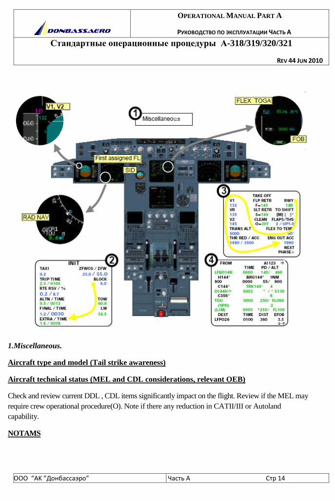
1.Miscellaneous.
Aircraft type and model (Tail strike awareness)
Aircraft technical status (MEL and CDL considerations, relevant OEB)
Check and review current DDL , CDL items significantly impact on the flight. Review if the MEL may
require crew operational procedure(O). Note if there any reduction in CATII/III or Autoland
capability.
NOTAMS
OPERATIONAL MANUAL PART A
РУКОВОДСТВО ПО ЭКСПЛУАТАЦИИ ЧАСТЬ А
Стандартные операционные процедуры А-318/319/320/321
REV 44 JUN 2010
ООО “АK ”Донбасcаэро” Часть A Стр 15
WEATHER
Review the possibility of any of the following:
-strong wind on take-off
-icing conditions on take-off and initial climb
-low visibility take-off
-operations in windshear
-weather avoidance after take-off
RWY conditions
Runway Dry/Wet/Contaminated/Icy/Short Field/Rough Surface
Use of ENG/Wings Anti ice
ENG Start Procedure
Push Back
Expected Taxi Clearance
Use of Radar
Use of Packs for Takeoff
Confirm packs configuration:
- PACKS ON - using ENG BLEED or APU BLEED ON;
- PACKS OFF
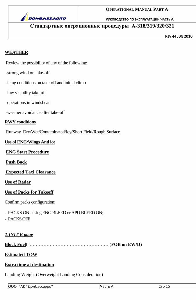
2. INIT B page
Block Fuel …………………………………………….(FOB on EW/D)
Estimated TOW
Extra time at destination
Landing Weight (Overweight Landing Consideration)
OPERATIONAL MANUAL PART A
РУКОВОДСТВО ПО ЭКСПЛУАТАЦИИ ЧАСТЬ А
Стандартные операционные процедуры А-318/319/320/321
REV 44 JUN 2010
ООО “АK ”Донбасcаэро” Часть A Стр 16
Ensure that no overweight landing expected in case of emergency return otherwise consider
landing configuration as well packs configuration
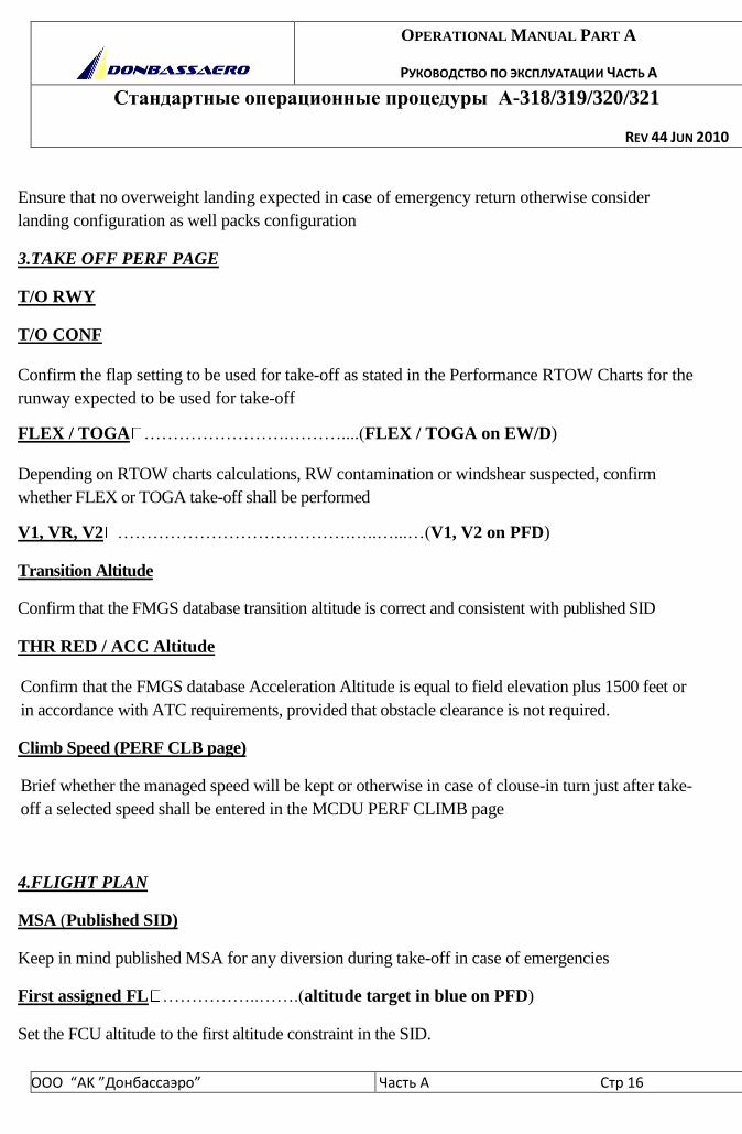
3.TAKE OFF PERF PAGE
T/O RWY
T/O CONF
Confirm the flap setting to be used for take-off as stated in the Performance RTOW Charts for the
runway expected to be used for take-off
FLEX / TOGA …………………….………....(FLEX / TOGA on EW/D)
Depending on RTOW charts calculations, RW contamination or windshear suspected, confirm
whether FLEX or TOGA take-off shall be performed
V1, VR, V2 ………………………………….…..…...…(V1, V2 on PFD)
Transition Altitude
Confirm that the FMGS database transition altitude is correct and consistent with published SID
THR RED / ACC Altitude
Confirm that the FMGS database Acceleration Altitude is equal to field elevation plus 1500 feet or
in accordance with ATC requirements, provided that obstacle clearance is not required.
Climb Speed (PERF CLB page)
Brief whether the managed speed will be kept or otherwise in case of clouse-in turn just after take-
off a selected speed shall be entered in the MCDU PERF CLIMB page
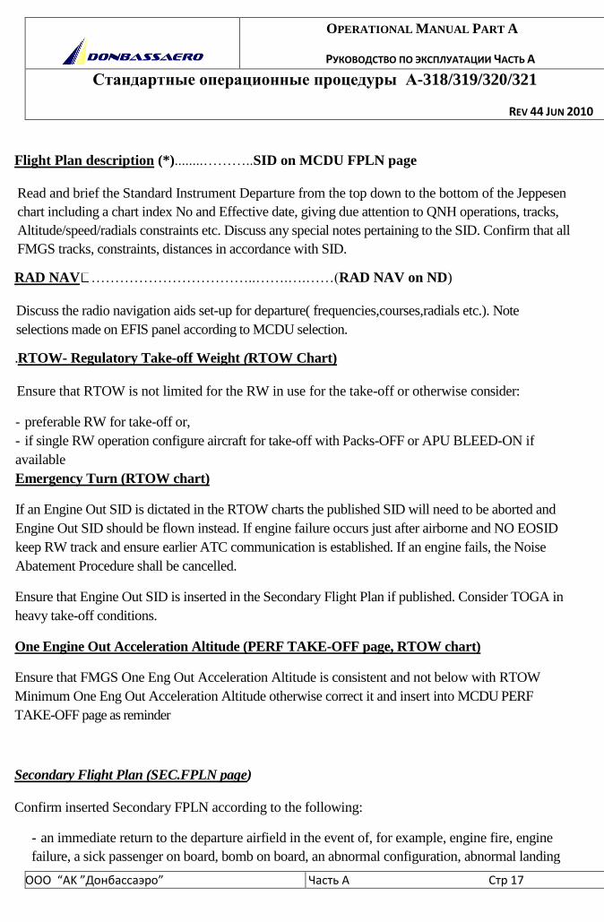
4.FLIGHT PLAN
MSA (Published SID)
Keep in mind published MSA for any diversion during take-off in case of emergencies
First assigned FL ……………..…….(altitude target in blue on PFD)
Set the FCU altitude to the first altitude constraint in the SID.
OPERATIONAL MANUAL PART A
РУКОВОДСТВО ПО ЭКСПЛУАТАЦИИ ЧАСТЬ А
Стандартные операционные процедуры А-318/319/320/321
REV 44 JUN 2010
ООО “АK ”Донбасcаэро” Часть A Стр 17
Flight Plan description (*)........………..SID on MCDU FPLN page
Read and brief the Standard Instrument Departure from the top down to the bottom of the Jeppesen
chart including a chart index No and Effective date, giving due attention to QNH operations, tracks,
Altitude/speed/radials constraints etc. Discuss any special notes pertaining to the SID. Confirm that all
FMGS tracks, constraints, distances in accordance with SID.
RAD NAV ……………………………..…….….……(RAD NAV on ND)
Discuss the radio navigation aids set-up for departure( frequencies,courses,radials etc.). Note
selections made on EFIS panel according to MCDU selection.
.RTOW- Regulatory Take-off Weight (RTOW Chart)
Ensure that RTOW is not limited for the RW in use for the take-off or otherwise consider:
- preferable RW for take-off or,
- if single RW operation configure aircraft for take-off with Packs-OFF or APU BLEED-ON if
available
Emergency Turn (RTOW chart)
If an Engine Out SID is dictated in the RTOW charts the published SID will need to be aborted and
Engine Out SID should be flown instead. If engine failure occurs just after airborne and NO EOSID
keep RW track and ensure earlier ATC communication is established. If an engine fails, the Noise
Abatement Procedure shall be cancelled.
Ensure that Engine Out SID is inserted in the Secondary Flight Plan if published. Consider TOGA in
heavy take-off conditions.
One Engine Out Acceleration Altitude (PERF TAKE-OFF page, RTOW chart)
Ensure that FMGS One Eng Out Acceleration Altitude is consistent and not below with RTOW
Minimum One Eng Out Acceleration Altitude otherwise correct it and insert into MCDU PERF
TAKE-OFF page as reminder
Secondary Flight Plan (SEC.FPLN page)
Confirm inserted Secondary FPLN according to the following:
- an immediate return to the departure airfield in the event of, for example, engine fire, engine
failure, a sick passenger on board, bomb on board, an abnormal configuration, abnormal landing

OPERATIONAL MANUAL PART A
РУКОВОДСТВО ПО ЭКСПЛУАТАЦИИ ЧАСТЬ А
Стандартные операционные процедуры А-318/319/320/321
REV 44 JUN 2010
ООО “АK ”Донбасcаэро” Часть A Стр 18
gear etc. It is recommended to insert performance data into SEC PERF APPROACH page or,
- if weather is below landing minimum or visibility less than 400m the diversion to the alternate
for take-off. Alternate for take-of should not be far than 1 hour flight time, approximately
380nm distance or,
- alternate RW for departure with modified SID and revised take-off data performance
items that must be cross-checked on associated display.
(*) PF will set ND display to PLAN mode with required range and CSTR and use scroll key to
check the whole FPLN thoroughly. PNF ensures that the inserted FPLN agrees with the planned
route.
R Discussion OEB(s) applicable
Abnormal operations
The decision to reject take-off and the stop is made by the Captain.
It is therefore recommended that the Captain keeps hands on the thrust levers until the aircraft
reaches V1, wheather he is Pilot Flying( PF) or Pilot Not Flying (PNF).
Reject or continue take-off in case of abnormalities or emergency is only Captain responsibility,
that is why he should confirm task sharing for the RTO and continued take-off events for each day of
flight or crew member changed as follow:
For any failure before V1:
CAPT will call STOP or GO .
In case of "STOP" CAPT will take stop actions:
thrust levers – idle
reverse thrust – max avail
steer the aircraft
parking brake- on after a/c stops
"Attention crew at station"
"ECAM action"
OPERATIONAL MANUAL PART A
РУКОВОДСТВО ПО ЭКСПЛУАТАЦИИ ЧАСТЬ А
Стандартные операционные процедуры А-318/319/320/321
REV 44 JUN 2010
ООО “АK ”Донбасcаэро” Часть A Стр 19
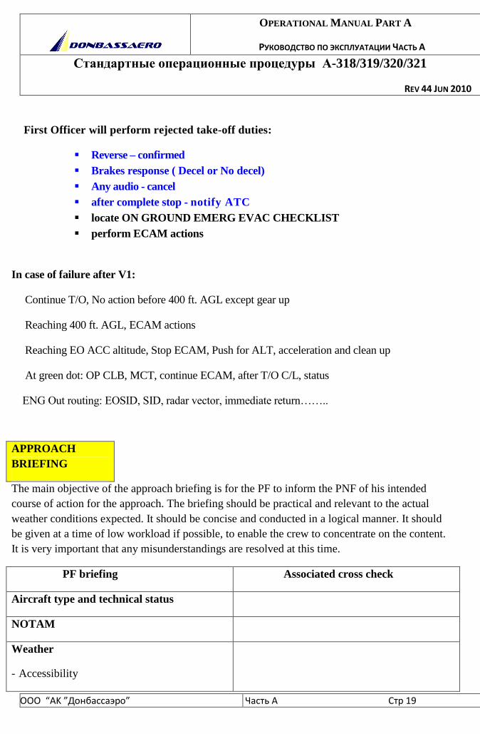
First Officer will perform rejected take-off duties:
Reverse – confirmed
Brakes response ( Decel or No decel)
Any audio - cancel
after complete stop - notify ATC
locate ON GROUND EMERG EVAC CHECKLIST
perform ECAM actions
In case of failure after V1:
Continue T/O, No action before 400 ft. AGL except gear up
Reaching 400 ft. AGL, ECAM actions
Reaching EO ACC altitude, Stop ECAM, Push for ALT, acceleration and clean up
At green dot: OP CLB, MCT, continue ECAM, after T/O C/L, status
ENG Out routing: EOSID, SID, radar vector, immediate return……..
APPROACH
BRIEFING
The main objective of the approach briefing is for the PF to inform the PNF of his intended
course of action for the approach. The briefing should be practical and relevant to the actual
weather conditions expected. It should be concise and conducted in a logical manner. It should
be given at a time of low workload if possible, to enable the crew to concentrate on the content.
It is very important that any misunderstandings are resolved at this time.
PF briefing Associated cross check
Aircraft type and technical status
NOTAM
Weather
- Accessibility
OPERATIONAL MANUAL PART A
РУКОВОДСТВО ПО ЭКСПЛУАТАЦИИ ЧАСТЬ А
Стандартные операционные процедуры А-318/319/320/321
REV 44 JUN 2010
ООО “АK ”Донбасcаэро” Часть A Стр 20
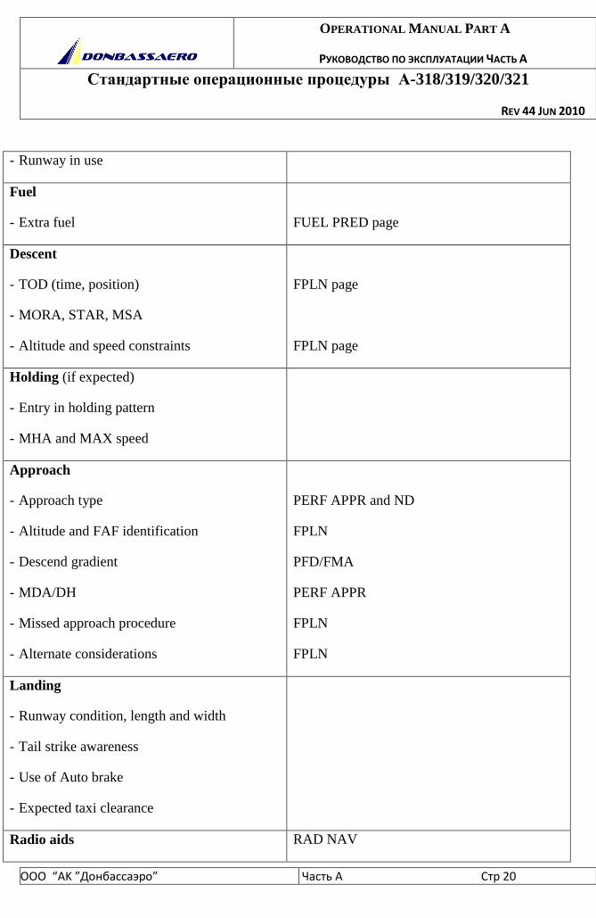
- Runway in use
Fuel
- Extra fuel
FUEL PRED page
Descent
- TOD (time, position)
- MORA, STAR, MSA
- Altitude and speed constraints
FPLN page
FPLN page
Holding (if expected)
- Entry in holding pattern
- MHA and MAX speed
Approach
- Approach type
- Altitude and FAF identification
- Descend gradient
- MDA/DH
- Missed approach procedure
- Alternate considerations
PERF APPR and ND
FPLN
PFD/FMA
PERF APPR
FPLN
FPLN
Landing
- Runway condition, length and width
- Tail strike awareness
- Use of Auto brake
- Expected taxi clearance
Radio aids RAD NAV
OPERATIONAL MANUAL PART A
РУКОВОДСТВО ПО ЭКСПЛУАТАЦИИ ЧАСТЬ А
Стандартные операционные процедуры А-318/319/320/321
REV 44 JUN 2010
ООО “АK ”Донбасcаэро” Часть A Стр 21
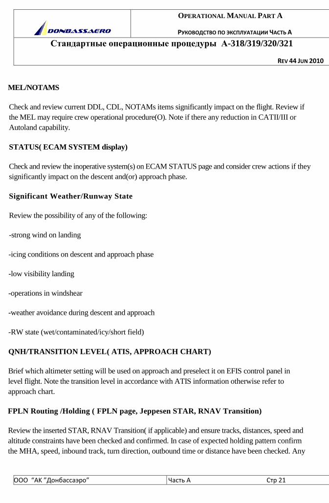
MEL/NOTAMS
Check and review current DDL, CDL, NOTAMs items significantly impact on the flight. Review if
the MEL may require crew operational procedure(O). Note if there any reduction in CATII/III or
Autoland capability.
STATUS( ECAM SYSTEM display)
Check and review the inoperative system(s) on ECAM STATUS page and consider crew actions if they
significantly impact on the descent and(or) approach phase.
Significant Weather/Runway State
Review the possibility of any of the following:
-strong wind on landing
-icing conditions on descent and approach phase
-low visibility landing
-operations in windshear
-weather avoidance during descent and approach
-RW state (wet/contaminated/icy/short field)
QNH/TRANSITION LEVEL( ATIS, APPROACH CHART)
Brief which altimeter setting will be used on approach and preselect it on EFIS control panel in
level flight. Note the transition level in accordance with ATIS information otherwise refer to
approach chart.
FPLN Routing /Holding ( FPLN page, Jeppesen STAR, RNAV Transition)
Review the inserted STAR, RNAV Transition( if applicable) and ensure tracks, distances, speed and
altitude constraints have been checked and confirmed. In case of expected holding pattern confirm
the MHA, speed, inbound track, turn direction, outbound time or distance have been checked. Any
OPERATIONAL MANUAL PART A
РУКОВОДСТВО ПО ЭКСПЛУАТАЦИИ ЧАСТЬ А
Стандартные операционные процедуры А-318/319/320/321
REV 44 JUN 2010
ООО “АK ”Донбасcаэро” Часть A Стр 22
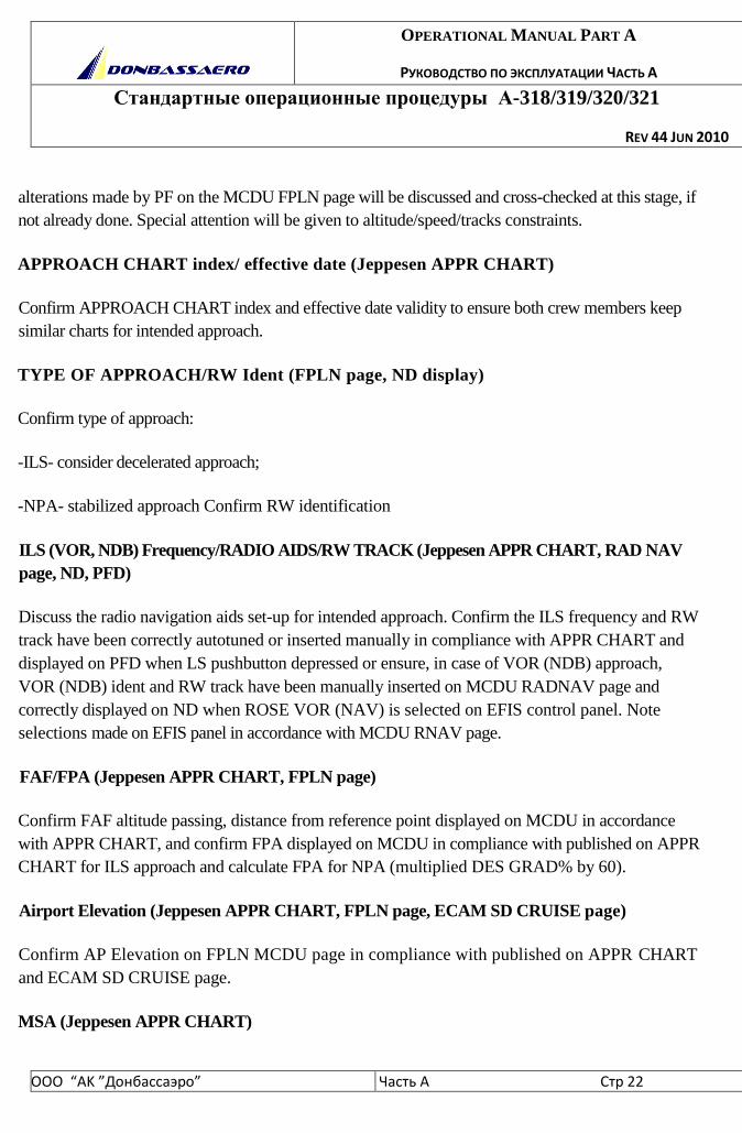
alterations made by PF on the MCDU FPLN page will be discussed and cross-checked at this stage, if
not already done. Special attention will be given to altitude/speed/tracks constraints.
APPROACH CHART index/ effective date (Jeppesen APPR CHART)
Confirm APPROACH CHART index and effective date validity to ensure both crew members keep
similar charts for intended approach.
TYPE OF APPROACH/RW Ident (FPLN page, ND display)
Confirm type of approach:
-ILS- consider decelerated approach;
-NPA- stabilized approach Confirm RW identification
ILS (VOR, NDB) Frequency/RADIO AIDS/RW TRACK (Jeppesen APPR CHART, RAD NAV
page, ND, PFD)
Discuss the radio navigation aids set-up for intended approach. Confirm the ILS frequency and RW
track have been correctly autotuned or inserted manually in compliance with APPR CHART and
displayed on PFD when LS pushbutton depressed or ensure, in case of VOR (NDB) approach,
VOR (NDB) ident and RW track have been manually inserted on MCDU RADNAV page and
correctly displayed on ND when ROSE VOR (NAV) is selected on EFIS control panel. Note
selections made on EFIS panel in accordance with MCDU RNAV page.
FAF/FPA (Jeppesen APPR CHART, FPLN page)
Confirm FAF altitude passing, distance from reference point displayed on MCDU in accordance
with APPR CHART, and confirm FPA displayed on MCDU in compliance with published on APPR
CHART for ILS approach and calculate FPA for NPA (multiplied DES GRAD% by 60).
Airport Elevation (Jeppesen APPR CHART, FPLN page, ECAM SD CRUISE page)
Confirm AP Elevation on FPLN MCDU page in compliance with published on APPR CHART
and ECAM SD CRUISE page.
MSA (Jeppesen APPR CHART)
OPERATIONAL MANUAL PART A
РУКОВОДСТВО ПО ЭКСПЛУАТАЦИИ ЧАСТЬ А
Стандартные операционные процедуры А-318/319/320/321
REV 44 JUN 2010
ООО “АK ”Донбасcаэро” Часть A Стр 23
Confirm MSA of Jeppesen chart. Crew awareness is necessary for any route deviation during
approach. Be aware of altitude passing and do not descend below MSA.
GS (FD) Altitude( Jeppesen APPR CHART, FPLN page)
Confirm GS Altitude passing for ILS approach or Final Descent Altitude for NPA and distance
from reference point displayed on MCDU in accordance with APPR CHART
Flaps ( MCDU PERF APPR page, QRH "Approach with one engine inoperative",
"Overweight Landing", "Circling with one engine inoperative", overhead
panel)
Consider flaps setting for approach consistent with circumstances:
- for windshear or downburst conditions- CONF 3;
- for severe turbulence or strong wing approach conditions aircraft is certified in
configuration FULL and CONF 3 however, CONF 3 provides more energy and less
drag;
- in case of approach with one engine inoperative be aware of "Approach with one engine
inoperative" or "Circling with one engine inoperative" QRH procedures to determine flaps setting;
- in case of emergency return consider "Overweight landing" QRH procedure.
Confirm GPWS FLAP 3 - ON for approach in CONF 3 on overhead panel.
VAPP (MCDU PERF APPR page, FPLN page, standby ASI)
Confirm Vapp on MCDU PERF APPR page and correct if required (for example approach in severe
icing conditions). Confirm Vapp have been inserted into MCDU FPLN page as speed constraint at
Final Descent point for intended stabilized approach. Confirm speed bugs setting on standby ASI.
MDA/DH (MCDU PERF APPR page, PFD, Jeppesen APPR CHART)
Confirm MDA/DH inserted into MCDU PERF APPR page and displayed on PFD in compliance
with Jeppesen chart.
GO AROUND (MCDU FPLN page, ND display, Jeppesen chart)
Read and brief GO AROUND procedure giving due attention to tracks, altitude/speed/radials
constraints. Discuss any special notes concerning flaps retraction, AP/FD/FMGS mode changes etc.
Confirm that all FMGS tracks, constraints, holdings in accordance with Jeppesen chart.
OPERATIONAL MANUAL PART A
РУКОВОДСТВО ПО ЭКСПЛУАТАЦИИ ЧАСТЬ А
Стандартные операционные процедуры А-318/319/320/321
REV 44 JUN 2010
ООО “АK ”Донбасcаэро” Часть A Стр 24
STOPPING (Jeppesen chart)
Brief autobrake and reverse using upon landing. Discuss if any landing distance
increment is expected. Note any restrictions required by Jeppesen chart for landing,
RW vacation, frequency change etc.
TAI/WXR/TERR
Brief TAI/WXR/TERR usage in accordance with circumstances.
ALTERNATE/EXTRA TIME (MCDU FPLN page, MCDU FUEL PRED page)
Confirm inserted flight plan to the alternate is correct and give due attention to
speed, altitude constraints. Confirm extra time and fuel is sufficient once any events
requiring holding occurs (low visibility.RW snow removal etc.), otherwise consider
deviate to the alternate without holding.
SEC.FPLN (MCDU SEC.FPLN page, CFPL)
Confirm inserted Secondary FPLN according to the following:
- copy of the Active FPLN;
- diversion to the spare alternate.
TYPE OF A/C
Note model type to keep due attention for tailstrike avoidance.
FLIGHT PREPARATION
TECHNICAL CONDITION OF THE
AIRCRAFT
OPERATIONAL MANUAL PART A
РУКОВОДСТВО ПО ЭКСПЛУАТАЦИИ ЧАСТЬ А
Стандартные операционные процедуры А-318/319/320/321
REV 44 JUN 2010
ООО “АK ”Донбасcаэро” Часть A Стр 25
- The crew will verify the technical state of the aircraft (Deferred Defect List), with regard to
airworthiness, acceptability of malfunctions (MEL), and influence on the flight plan.
WEATHER
BRIEFING
- The crew will get a weather briefing.
- The briefing should include:
• Actual and expected weather conditions, including runway conditions for takeoff and
climb-out.
• Significant weather enroute, including winds and temperatures.
• Terminal forecasts for destination and alternate airports.
• Actual weather for destination and alternates, for short range flights and recent
pastweather, if available.
• Survey of the meteorological conditions at airports along the planned route.
Weather can affect the choice of routing (for example, influence which route is quickest) and the
choice of flight level. The flight crew must also consider the possibility of runways being
contaminated at the departure and destination airfields. The flight crew must also verify ISA
deviations and enroute icing conditions, and must consider the possibility of holding due to
weather at the destination.
NOTAMS
- The flight crew must examine NOTAMs for changes to routings, unserviceable navaids,
availability of runways and approach aids etc, all of which may affect the final fuel requirement.
OPERATIONAL MANUAL PART A
РУКОВОДСТВО ПО ЭКСПЛУАТАЦИИ ЧАСТЬ А
Стандартные операционные процедуры А-318/319/320/321
REV 44 JUN 2010
ООО “АK ”Донбасcаэро” Часть A Стр 26
- In order to prevent the risks of projection of debris towards the trimmable horizontal stabilizer
and the elevators, it is not recommended to takeoff from runways in bad condition (loose surface,
under repair, covered with debris.....)
FLIGHT PLAN AND OPERATIONAL
REQUIREMENTS
- The crew will check the company flight plan for routing, altitudes, and flight time.
- The Captain will check the ATC flight plan and ensure that it:
• Is filled in and filed, in accordance with the prescribed procedures,
• It agrees with the fuel flight plan routing.
- The crew will check the estimated load figures, and will calculate the maximum allowable
takeoff and landing weights.
OPTIMUM FLIGHT
LEVEL
The flight crew should choose a flight level that is as close to the optimum as possible. To
obtain the optimum flight level, use the chart in the QRH or in the FCOM (Refer to FCOM
2.05.20).
As a general rule, an altitude that is 4000 feet below the optimum produces a significant penalty
(approximately 5 % of fuel). Flight 8000 feet below the optimum altitude produces a penalty of
more than 10 % against trip fuel. (The usual contingency allowance is 5 %).
FUEL
OPERATIONAL MANUAL PART A
РУКОВОДСТВО ПО ЭКСПЛУАТАЦИИ ЧАСТЬ А
Стандартные операционные процедуры А-318/319/320/321
REV 44 JUN 2010
ООО “АK ”Донбасcаэро” Часть A Стр 27
REQUIREMENTS
COMPUTERIZED FLIGHT PLAN CHECK
In most cases the flight crew uses a computer-derived flight plan to obtain the correct fuel
requirements.
Although these computerized requirements are normally accurate, the flight crew must check
them for gross errors.
The easiest way to do this is to use the "Quick Determination of F-PLN" tables in FCOM
2.05.40.
Although the aircraft will fly at ECON MACH that is based on the cost index, the 0.78 Mach
table is accurate enough to permit the crew to check for gross error. Ensure that both the captain
and the first officer have verified that the fuel calculations and required fuel on board are correct
and that the figure complies with the applicable regulations.
*Note: It’s a Company Policy that PNF is in full responsibility:
- for A/C refueling, - refueling coupling check, and - all refueling paper bill confirmations. All thease actions must be fulfilled after completing of refueling procedure and checks
FUEL TRANSPORTATION
The Flight crew must check th policy covering the «tankering» of fuel on sectors where there is
favourable fuel price diferential or operational requirement.
Remember that carring unnecessary exra fuel increases the fuel consumption for that sector and
therefore reduces the economy of the operation (lower flex temperature, more tire wear, lower
optimum altitude etc.)
OPERATIONAL MANUAL PART A
РУКОВОДСТВО ПО ЭКСПЛУАТАЦИИ ЧАСТЬ А
Стандартные операционные процедуры А-318/319/320/321
REV 44 JUN 2010
ООО “АK ”Донбасcаэро” Часть A Стр 28
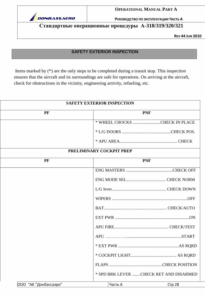
SAFETY EXTERIOR INSPECTION
Items marked by (*) are the only steps to be completed during a transit stop. This inspection
ensures that the aircraft and its surroundings are safe for operations. On arriving at the aircraft,
check for obstructions in the vicinity, engineering activity, refueling, etc.
SAFETY EXTERIOR INSPECTION
PF PNF
* WHEEL CHOCKS ..........................CHECK IN PLACE
* L/G DOORS ..............................................CHECK POS.
* APU AREA...................................................... CHECK
PRELIMINARY COCKPIT PREP
PF PNF
ENG MASTERS ............................................CHECK OFF
ENG MODE SEL..................................... CHECK NORM
L/G lever................................................... CHECK DOWN
WIPERS .......................................................................OFF
BAT........................................................... CHECK/AUTO
EXT PWR ......................................................................ON
APU FIRE................................................... CHECK/TEST
APU ……………....................................................START
* EXT PWR .........................................................AS RQRD
* COCKPIT LIGHT........................................... AS RQRD
FLAPS ..................................................CHECK POSITION
* SPD BRK LEVER ........CHECK RET AND DISARMED
OPERATIONAL MANUAL PART A
РУКОВОДСТВО ПО ЭКСПЛУАТАЦИИ ЧАСТЬ А
Стандартные операционные процедуры А-318/319/320/321
REV 44 JUN 2010
ООО “АK ”Донбасcаэро” Часть A Стр 29
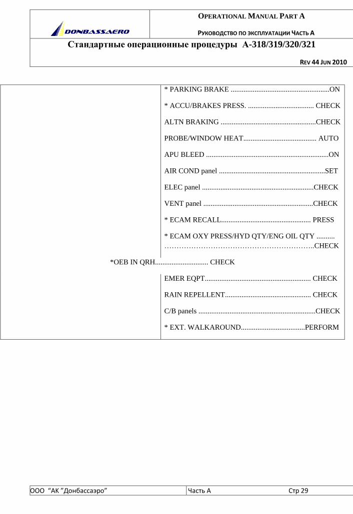
* PARKING BRAKE ......................................................ON
* ACCU/BRAKES PRESS. .................................... CHECK
ALTN BRAKING ....................................................CHECK
PROBE/WINDOW HEAT........................................ AUTO
APU BLEED ...................................................................ON
AIR COND panel ..........................................................SET
ELEC panel .............................................................CHECK
VENT panel ............................................................CHECK
* ECAM RECALL................................................. PRESS
* ECAM OXY PRESS/HYD QTY/ENG OIL QTY ..........
……………………………………………………..CHECK
*OEB IN QRH............................. CHECK
EMER EQPT.......................................................... CHECK
RAIN REPELLENT............................................... CHECK
C/B panels ................................................................CHECK
* EXT. WALKAROUND...................................PERFORM

OPERATIONAL MANUAL PART A
РУКОВОДСТВО ПО ЭКСПЛУАТАЦИИ ЧАСТЬ А
Стандартные операционные процедуры А-318/319/320/321
REV 44 JUN 2010
ООО “АK ”Донбасcаэро” Часть A Стр 30
COCKPIT PREPARATION
PF PNF
* GEAR PINS & COVERS .........................CHECK
OVERHEAD PANEL
* ALL WHITE LIGHTS....................EXTINGUISH
* RCDR GND CTL ..............................................ON
CVR ...................................................................TEST
EVAC ........................................................AS RQRD
* ADIRS.......................................................... NAV
EXTERIOR LIGHTS ..............................AS RQRD
* SIGNS..............................................................SET
LDG ELEV.................................................... AUTO
* PACK FLOW…...................................AS RQRD
BAT.............................................................. CHECK
ENG FIRE...........................................CHECK/TEST
AUDIO SWITCH .........................................NORM
PA (3rd occupant)........................................RECEPT
MAINT PANEL ...........................................CHECK
CTR INSTRUMENT PANEL:
* STBY INSTRUMENTS ............................CHECK
*CLOCK......................................CHECK/ADJUST
* A/SKID N/W STRG ........................................ON
OPERATIONAL MANUAL PART A
РУКОВОДСТВО ПО ЭКСПЛУАТАЦИИ ЧАСТЬ А
Стандартные операционные процедуры А-318/319/320/321
REV 44 JUN 2010
ООО “АK ”Донбасcаэро” Часть A Стр 31
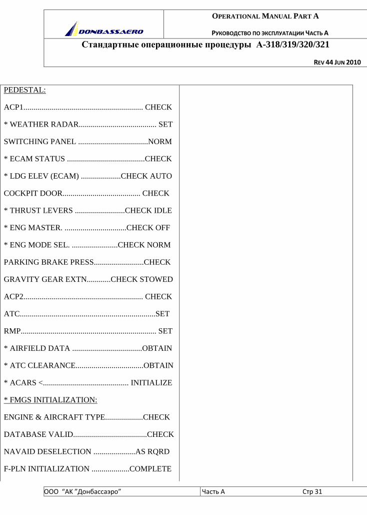
PEDESTAL:
ACP1............................................................ CHECK
* WEATHER RADAR....................................... SET
SWITCHING PANEL ...................................NORM
* ECAM STATUS .......................................CHECK
* LDG ELEV (ECAM) ....................CHECK AUTO
COCKPIT DOOR....................................... CHECK
* THRUST LEVERS .........................CHECK IDLE
* ENG MASTER. ...............................CHECK OFF
* ENG MODE SEL. .......................CHECK NORM
PARKING BRAKE PRESS.........................CHECK
GRAVITY GEAR EXTN............CHECK STOWED
ACP2............................................................ CHECK
ATC....................................................................SET
RMP.................................................................... SET
* AIRFIELD DATA ...................................OBTAIN
* ATC CLEARANCE..................................OBTAIN
* ACARS <........................................... INITIALIZE
* FMGS INITIALIZATION:
ENGINE & AIRCRAFT TYPE...................CHECK
DATABASE VALID.....................................CHECK
NAVAID DESELECTION .....................AS RQRD
F-PLN INITIALIZATION ...................COMPLETE
OPERATIONAL MANUAL PART A
РУКОВОДСТВО ПО ЭКСПЛУАТАЦИИ ЧАСТЬ А
Стандартные операционные процедуры А-318/319/320/321
REV 44 JUN 2010
ООО “АK ”Донбасcаэро” Часть A Стр 32
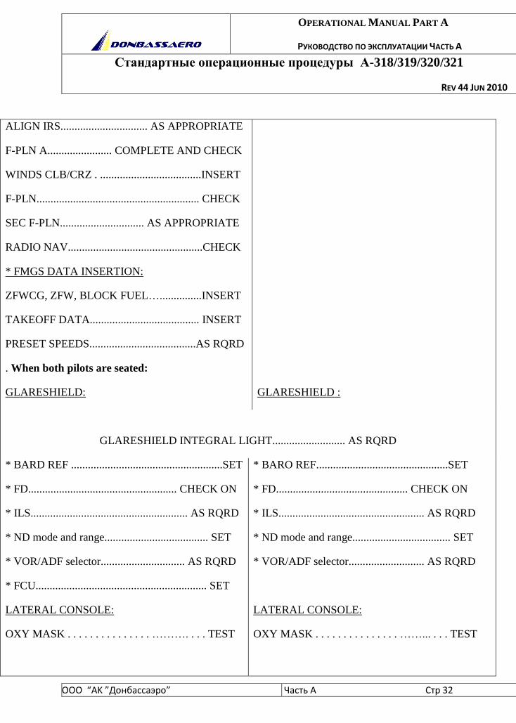
ALIGN IRS............................... AS APPROPRIATE
F-PLN A....................... COMPLETE AND CHECK
WINDS CLB/CRZ . ....................................INSERT
F-PLN.......................................................... CHECK
SEC F-PLN.............................. AS APPROPRIATE
RADIO NAV................................................CHECK
* FMGS DATA INSERTION:
ZFWCG, ZFW, BLOCK FUEL…...............INSERT
TAKEOFF DATA....................................... INSERT
PRESET SPEEDS......................................AS RQRD
. When both pilots are seated:
GLARESHIELD:
GLARESHIELD :
GLARESHIELD INTEGRAL LIGHT.......................... AS RQRD
* BARD REF ......................................................SET
* FD..................................................... CHECK ON
* ILS........................................................ AS RQRD
* ND mode and range..................................... SET
* VOR/ADF selector.............................. AS RQRD
* FCU............................................................. SET
LATERAL CONSOLE:
OXY MASK . . . . . . . . . . . . . . . ………. . . . TEST
* BARO REF...............................................SET
* FD............................................... CHECK ON
* ILS.................................................... AS RQRD
* ND mode and range................................... SET
* VOR/ADF selector........................... AS RQRD
LATERAL CONSOLE:
OXY MASK . . . . . . . . . . . . . . . ……... . . . TEST
OPERATIONAL MANUAL PART A
РУКОВОДСТВО ПО ЭКСПЛУАТАЦИИ ЧАСТЬ А
Стандартные операционные процедуры А-318/319/320/321
REV 44 JUN 2010
ООО “АK ”Донбасcаэро” Часть A Стр 33
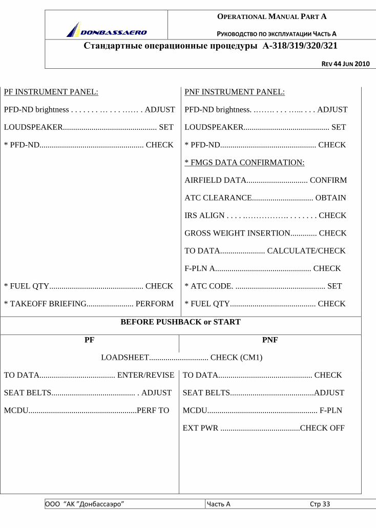
PF INSTRUMENT PANEL:
PFD-ND brightness . . . . . . . … . . . …… . ADJUST
LOUDSPEAKER.............................................. SET
* PFD-ND................................................... CHECK
* FUEL QTY.............................................. CHECK
* TAKEOFF BRIEFING....................... PERFORM
PNF INSTRUMENT PANEL:
PFD-ND brightness. .……. . . . …... . . . ADJUST
LOUDSPEAKER.......................................... SET
* PFD-ND............................................... CHECK
* FMGS DATA CONFIRMATION:
AIRFIELD DATA.............................. CONFIRM
ATC CLEARANCE.............................. OBTAIN
IRS ALIGN . . . . .……………. . . . . . . . CHECK
GROSS WEIGHT INSERTION............. CHECK
TO DATA...................... CALCULATE/CHECK
F-PLN A............................................... CHECK
* ATC CODE. ............................................ SET
* FUEL QTY.......................................... CHECK
BEFORE PUSHBACK or START
PF PNF
LOADSHEET............................. CHECK (CM1)
TO DATA..................................... ENTER/REVISE
SEAT BELTS......................................... . ADJUST
MCDU.....................................................PERF TO
TO DATA.............................................. CHECK
SEAT BELTS.........................................ADJUST
MCDU...................................................... F-PLN
EXT PWR .......................................CHECK OFF

OPERATIONAL MANUAL PART A
РУКОВОДСТВО ПО ЭКСПЛУАТАЦИИ ЧАСТЬ А
Стандартные операционные процедуры А-318/319/320/321
REV 44 JUN 2010
ООО “АK ”Донбасcаэро” Часть A Стр 34
CM1 CM2
BEFORE START C/L DOWN TO THE LINE
NW STRG DISC...................... CHECK AS RQRD
WINDOWS/DOORS .................................CHECK
THR LEVERS............................................... IDLE
PARK BRK ACCU PRESS...................... CHECK
PARKING BRAKE............................... AS RQRD
BEFORE START C/L BELOW THE LINE
PUSH BACK/START CLEAR............. OBTAIN
WINDOWS. .............................................CHECK
BEACON........................................................ ON
OPERATIONAL MANUAL PART A
РУКОВОДСТВО ПО ЭКСПЛУАТАЦИИ ЧАСТЬ А
Стандартные операционные процедуры А-318/319/320/321
REV 44 JUN 2010
ООО “АK ”Донбасcаэро” Часть A Стр 35
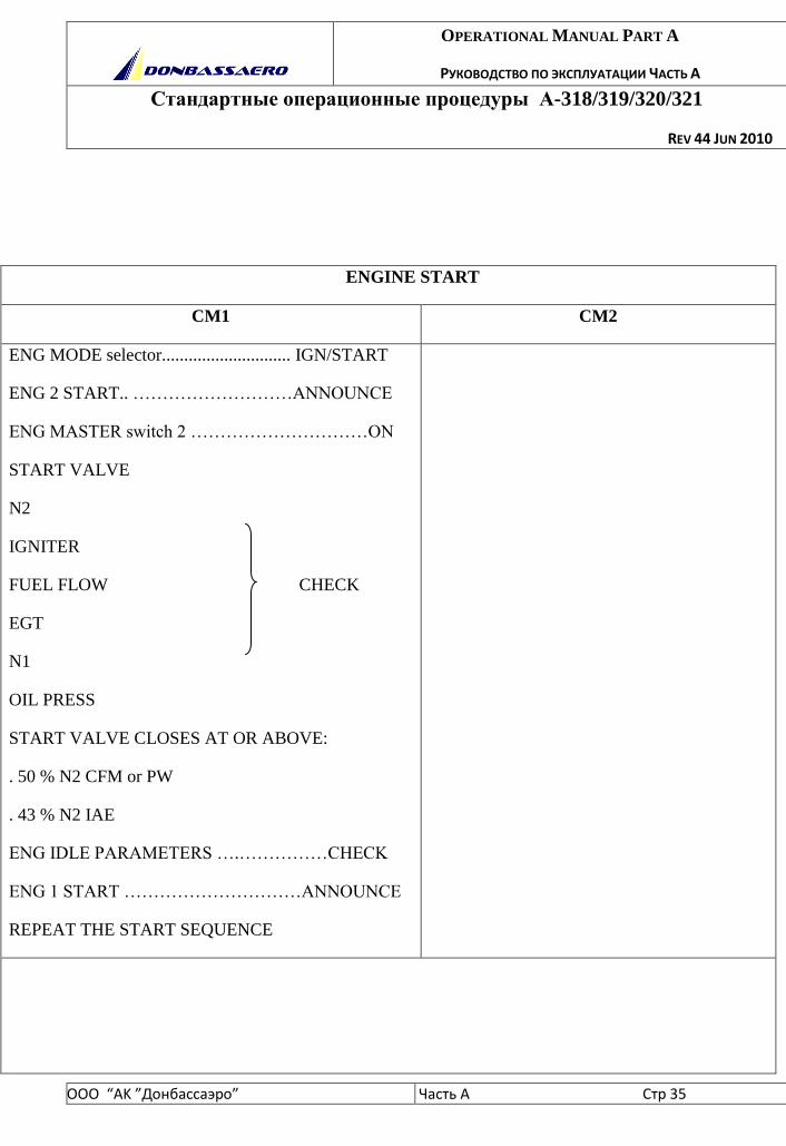
ENGINE START
CM1 CM2
ENG MODE selector............................. IGN/START
ENG 2 START.. ………………………ANNOUNCE
ENG MASTER switch 2 …………………………ON
START VALVE
N2
IGNITER
FUEL FLOW CHECK
EGT
N1
OIL PRESS
START VALVE CLOSES AT OR ABOVE:
. 50 % N2 CFM or PW
. 43 % N2 IAE
ENG IDLE PARAMETERS ….……………CHECK
ENG 1 START …………………………ANNOUNCE
REPEAT THE START SEQUENCE
OPERATIONAL MANUAL PART A
РУКОВОДСТВО ПО ЭКСПЛУАТАЦИИ ЧАСТЬ А
Стандартные операционные процедуры А-318/319/320/321
REV 44 JUN 2010
ООО “АK ”Донбасcаэро” Часть A Стр 36
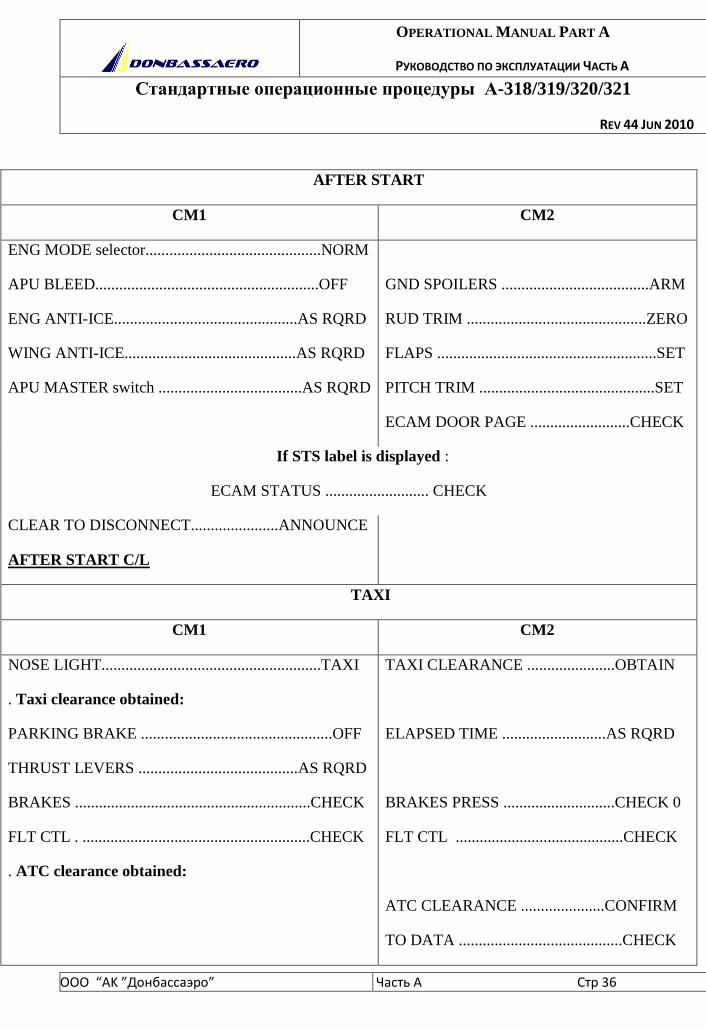
AFTER START
CM1 CM2
ENG MODE selector............................................NORM
APU BLEED........................................................OFF
ENG ANTI-ICE..............................................AS RQRD
WING ANTI-ICE...........................................AS RQRD
APU MASTER switch ....................................AS RQRD
GND SPOILERS .....................................ARM
RUD TRIM .............................................ZERO
FLAPS .......................................................SET
PITCH TRIM ............................................SET
ECAM DOOR PAGE .........................CHECK
If STS label is displayed :
ECAM STATUS .......................... CHECK
CLEAR TO DISCONNECT......................ANNOUNCE
AFTER START C/L
TAXI
CM1 CM2
NOSE LIGHT.......................................................TAXI
. Taxi clearance obtained:
PARKING BRAKE ................................................OFF
THRUST LEVERS ........................................AS RQRD
BRAKES ...........................................................CHECK
FLT CTL . .........................................................CHECK
. ATC clearance obtained:
TAXI CLEARANCE ......................OBTAIN
ELAPSED TIME ..........................AS RQRD
BRAKES PRESS ............................CHECK 0
FLT CTL ..........................................CHECK
ATC CLEARANCE .....................CONFIRM
TO DATA .........................................CHECK

OPERATIONAL MANUAL PART A
РУКОВОДСТВО ПО ЭКСПЛУАТАЦИИ ЧАСТЬ А
Стандартные операционные процедуры А-318/319/320/321
REV 44 JUN 2010
ООО “АK ”Донбасcаэро” Часть A Стр 37
FLT INST & FMA....................................... CHECK
TERR ON ND <........................................... AS RQRD
FMGS F-PLAN/SPD……………….CHECK
FCU ALT/HDG .......................................SET
BOTH FD....................................CHECK ON
FLT INST & FMA .........................CHECK
RADAR and PREDICTIVE WINOSHEAR
SYSTEM<......................................AS RQRD
ATC CODE. ..........................CONFIRM/SET
TERR ON ND <........................ . AS RQRD
AUTO BRK......................................... MAX
TO BRIEFING ...........................CONFIRM (PF)
CABIN REPORT........................................ RECEIVE
BEFORE TO C/L DOWN TO THE LINE
TO CONFIG. .....................................PRESS
TO MEMO..................... CHECK NO BLUE
OPERATIONAL MANUAL PART A
РУКОВОДСТВО ПО ЭКСПЛУАТАЦИИ ЧАСТЬ А
Стандартные операционные процедуры А-318/319/320/321
REV 44 JUN 2010
ООО “АK ”Донбасcаэро” Часть A Стр 38
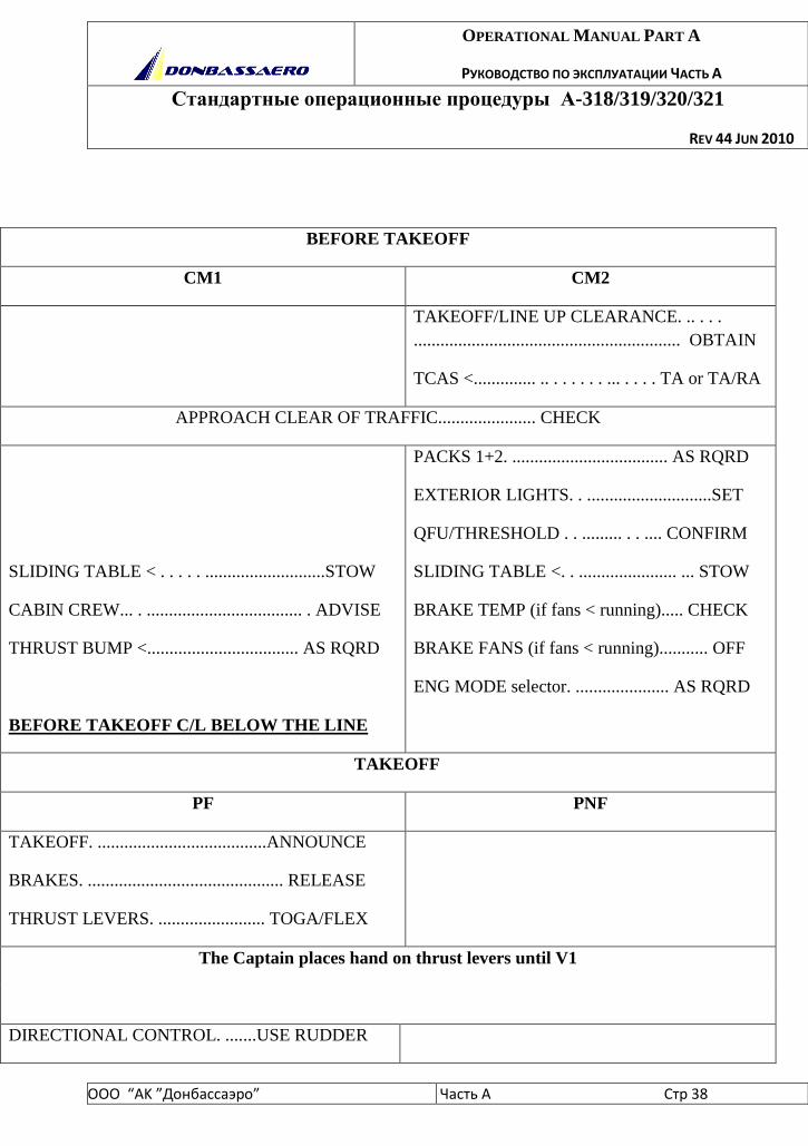
BEFORE TAKEOFF
CM1 CM2
TAKEOFF/LINE UP CLEARANCE. .. . . .
............................................................ OBTAIN
TCAS <.............. .. . . . . . . ... . . . . TA or TA/RA
APPROACH CLEAR OF TRAFFIC...................... CHECK
SLIDING TABLE < . . . . . ...........................STOW
CABIN CREW... . ................................... . ADVISE
THRUST BUMP <.................................. AS RQRD
BEFORE TAKEOFF C/L BELOW THE LINE
PACKS 1+2. ................................... AS RQRD
EXTERIOR LIGHTS. . ............................SET
QFU/THRESHOLD . . ......... . . .... CONFIRM
SLIDING TABLE <. . ...................... ... STOW
BRAKE TEMP (if fans < running)..... CHECK
BRAKE FANS (if fans < running)........... OFF
ENG MODE selector. ..................... AS RQRD
TAKEOFF
PF PNF
TAKEOFF. ......................................ANNOUNCE
BRAKES. ............................................ RELEASE
THRUST LEVERS. ........................ TOGA/FLEX
The Captain places hand on thrust levers until V1
DIRECTIONAL CONTROL. .......USE RUDDER
OPERATIONAL MANUAL PART A
РУКОВОДСТВО ПО ЭКСПЛУАТАЦИИ ЧАСТЬ А
Стандартные операционные процедуры А-318/319/320/321
REV 44 JUN 2010
ООО “АK ”Донбасcаэро” Часть A Стр 39
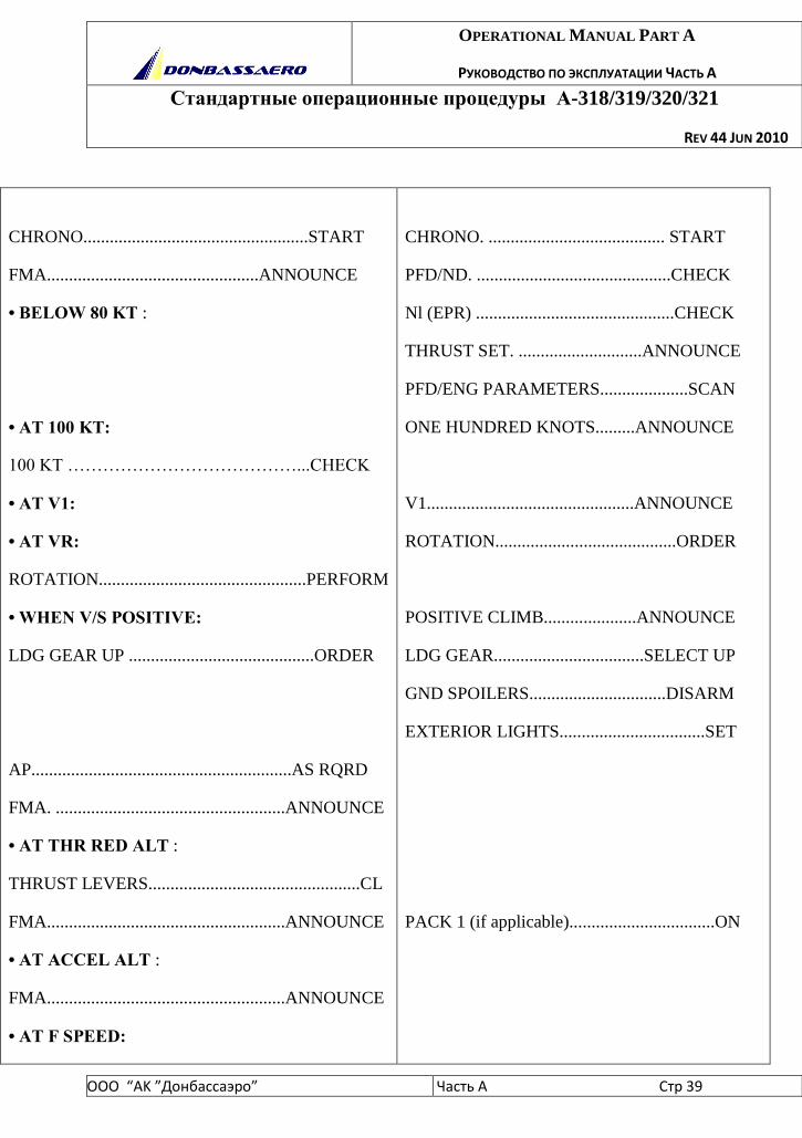
CHRONO...................................................START
FMA................................................ANNOUNCE
• BELOW 80 KT :
• AT 100 KT:
100 KT …………………………………...CHECK
• AT V1:
• AT VR:
ROTATION...............................................PERFORM
• WHEN V/S POSITIVE:
LDG GEAR UP ..........................................ORDER
AP...........................................................AS RQRD
FMA. ....................................................ANNOUNCE
• AT THR RED ALT :
THRUST LEVERS................................................CL
FMA......................................................ANNOUNCE
• AT ACCEL ALT :
FMA......................................................ANNOUNCE
• AT F SPEED:
CHRONO. ........................................ START
PFD/ND. ............................................CHECK
Nl (EPR) .............................................CHECK
THRUST SET. ............................ANNOUNCE
PFD/ENG PARAMETERS....................SCAN
ONE HUNDRED KNOTS.........ANNOUNCE
V1...............................................ANNOUNCE
ROTATION.........................................ORDER
POSITIVE CLIMB.....................ANNOUNCE
LDG GEAR..................................SELECT UP
GND SPOILERS...............................DISARM
EXTERIOR LIGHTS.................................SET
PACK 1 (if applicable).................................ON
OPERATIONAL MANUAL PART A
РУКОВОДСТВО ПО ЭКСПЛУАТАЦИИ ЧАСТЬ А
Стандартные операционные процедуры А-318/319/320/321
REV 44 JUN 2010
ООО “АK ”Донбасcаэро” Часть A Стр 40
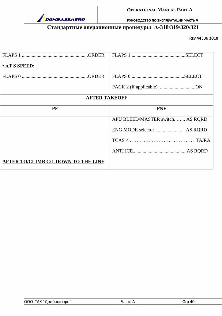
FLAPS 1 ......................................................ORDER
• AT S SPEED:
FLAPS 0 ......................................................ORDER
FLAPS 1 ............................................SELECT
FLAPS 0 ...........................................SELECT
PACK 2 (if applicable). .............................ON
AFTER TAKEOFF
PF PNF
AFTER TO/CLIMB C/L DOWN TO THE LINE
APU BLEED/MASTER switch. …... AS RQRD
ENG MODE selector....................... . AS RQRD
TCAS < . . . . . ………. . . . . . . . . . . . . . . . TA/RA
ANTI ICE........................................... AS RQRD
OPERATIONAL MANUAL PART A
РУКОВОДСТВО ПО ЭКСПЛУАТАЦИИ ЧАСТЬ А
Стандартные операционные процедуры А-318/319/320/321
REV 44 JUN 2010
ООО “АK ”Донбасcаэро” Часть A Стр 41
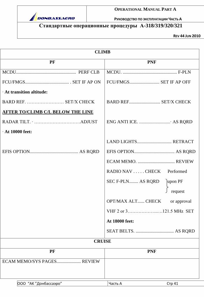
CLIMB
PF PNF
MCDU.................................................... PERF CLB
FCU/FMGS...................................... . SET IF AP ON
· At transition altitude:
BARD REF. …………………… SET/X CHECK
AFTER TO/CLIMB C/L BELOW THE LINE
RADAR TILT. · …………………………ADJUST
· At 10000 feet:
EFIS OPTION.......................................... AS RQRD
MCDU. ............................................... F-PLN
FCU/FMGS.......................... SET IF AP OFF
BARD REF........................... SET/X CHECK
ENG ANTI ICE. ...........................· AS RQRD
LAND LIGHTS.............................. RETRACT
EFIS OPTION................................... AS RQRD
ECAM MEMO. ................................ REVIEW
RADIO NAV . . . . . CHECK Performed
SEC F-PLN........ AS RQRD upon PF
request
OPT/MAX ALT...... CHECK or approval
VHF 2 or 3……………….….121.5 MHz SET
At 18000 feet:
SEAT BELTS. ................................. AS RQRD
CRUISE
PF PNF
ECAM MEMO/SYS PAGES..................... REVIEW

OPERATIONAL MANUAL PART A
РУКОВОДСТВО ПО ЭКСПЛУАТАЦИИ ЧАСТЬ А
Стандартные операционные процедуры А-318/319/320/321
REV 44 JUN 2010
ООО “АK ”Донбасcаэро” Часть A Стр 42
FLIGHT PROGRESS................................... CHECK
FUEL. ·.......................................................MONITOR
NAV ACCURACY...................................... CHECK
RADAR TILT. ..........................................· ADJUST
CABIN TEMP. ......................................· MONITOR
DESCENT PREPARATION
PF PNF
LDG ELEV................................................. CHECK
FMGS. .....................................................· PREPARE
APPR BRIEFING ................................. · PERFORM
AUTO BRK ........................................... · AS RQRD
LANDING DATA........................... PREPARE
FMGS............................................ PREPARE
GPWS LDG FLAP 3 ..................... · AS RQRD
DESCENT CLEARANCE............... . OBTAIN
ANTI ICE. ·...................................... AS RQRD
DESCENT
PF PNF
DESCENT. ..............................................· INITIATE
FMA. ................................................. ANNOUNCE
MCDU............................... PROG/PERF DESCENT
DESCENT. ·............................................ MONITOR
SPEEDBRAKES................................... · AS RQRD
RADAR TILT. ..........................................· ADJUST
FMA..................................................... CHECK
MCDU. ................................................ F-PLN
OPERATIONAL MANUAL PART A
РУКОВОДСТВО ПО ЭКСПЛУАТАЦИИ ЧАСТЬ А
Стандартные операционные процедуры А-318/319/320/321
REV 44 JUN 2010
ООО “АK ”Донбасcаэро” Часть A Стр 43
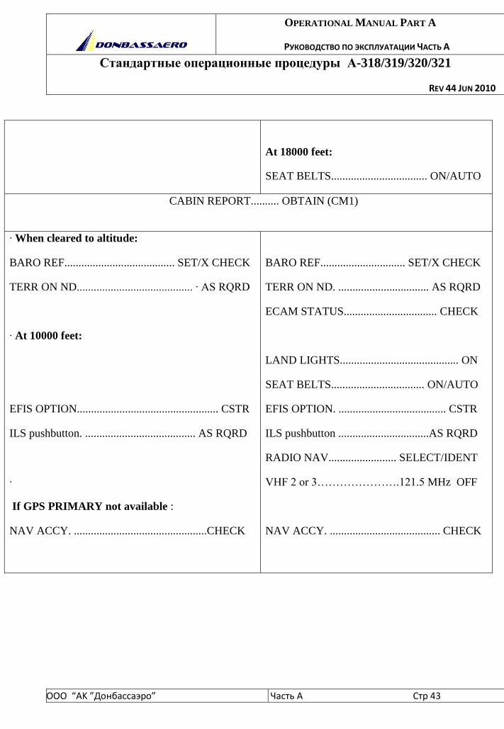
At 18000 feet:
SEAT BELTS.................................. ON/AUTO
CABIN REPORT.......... OBTAIN (CM1)
· When cleared to altitude:
BARO REF....................................... SET/X CHECK
TERR ON ND......................................... · AS RQRD
· At 10000 feet:
EFIS OPTION.................................................. CSTR
ILS pushbutton. ....................................... AS RQRD
·
If GPS PRIMARY not available :
NAV ACCY. ...............................................CHECK
BARO REF.............................. SET/X CHECK
TERR ON ND. ................................ AS RQRD
ECAM STATUS................................. CHECK
LAND LIGHTS.......................................... ON
SEAT BELTS................................. ON/AUTO
EFIS OPTION. ...................................... CSTR
ILS pushbutton ................................AS RQRD
RADIO NAV........................ SELECT/IDENT
VHF 2 or 3………………….121.5 MHz OFF
NAV ACCY. ....................................... CHECK
OPERATIONAL MANUAL PART A
РУКОВОДСТВО ПО ЭКСПЛУАТАЦИИ ЧАСТЬ А
Стандартные операционные процедуры А-318/319/320/321
REV 44 JUN 2010
ООО “АK ”Донбасcаэро” Часть A Стр 44
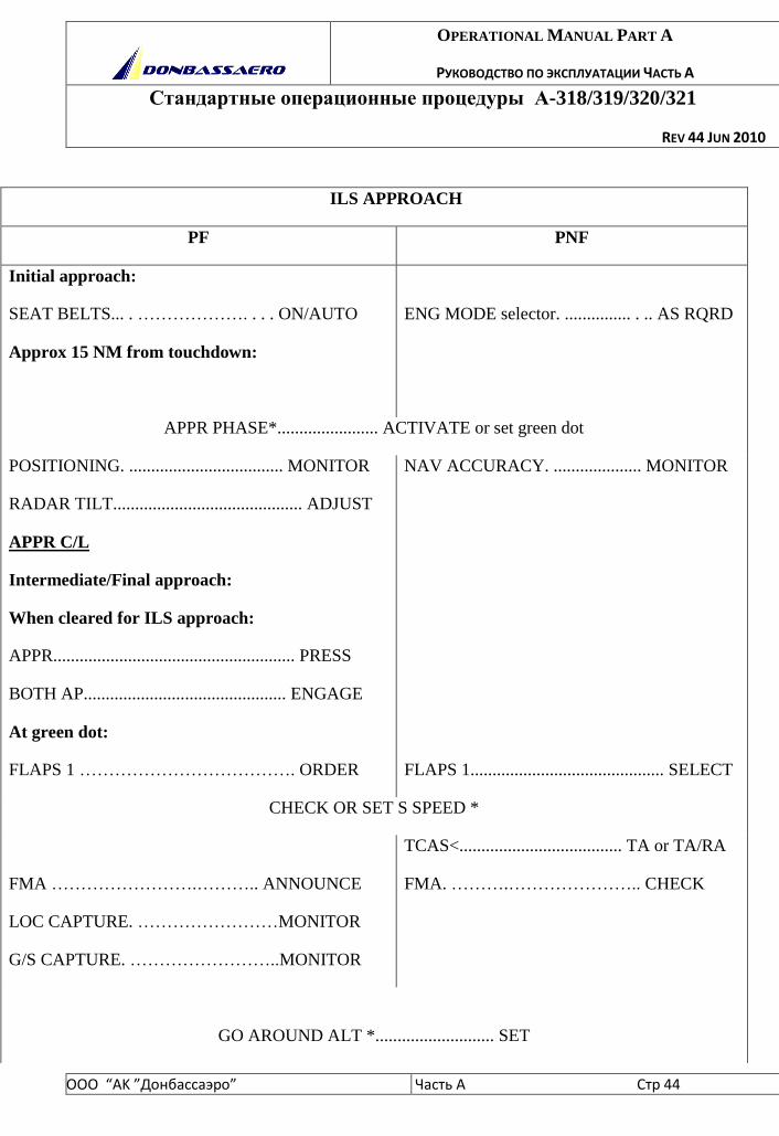
ILS APPROACH
PF PNF
Initial approach:
SEAT BELTS... . ………………. . . . ON/AUTO
Approx 15 NM from touchdown:
ENG MODE selector. ............... . .. AS RQRD
APPR PHASE*....................... ACTIVATE or set green dot
POSITIONING. ................................... MONITOR
RADAR TILT........................................... ADJUST
APPR C/L
Intermediate/Final approach:
When cleared for ILS approach:
APPR....................................................... PRESS
BOTH AP.............................................. ENGAGE
At green dot:
FLAPS 1 ………………………………. ORDER
NAV ACCURACY. .................... MONITOR
FLAPS 1............................................ SELECT
CHECK OR SET S SPEED *
FMA …………………….……….. ANNOUNCE
LOC CAPTURE. ……………………MONITOR
G/S CAPTURE. ……………………..MONITOR
TCAS<..................................... TA or TA/RA
FMA. ……….………………….. CHECK
GO AROUND ALT *........................... SET
OPERATIONAL MANUAL PART A
РУКОВОДСТВО ПО ЭКСПЛУАТАЦИИ ЧАСТЬ А
Стандартные операционные процедуры А-318/319/320/321
REV 44 JUN 2010
ООО “АK ”Донбасcаэро” Часть A Стр 45
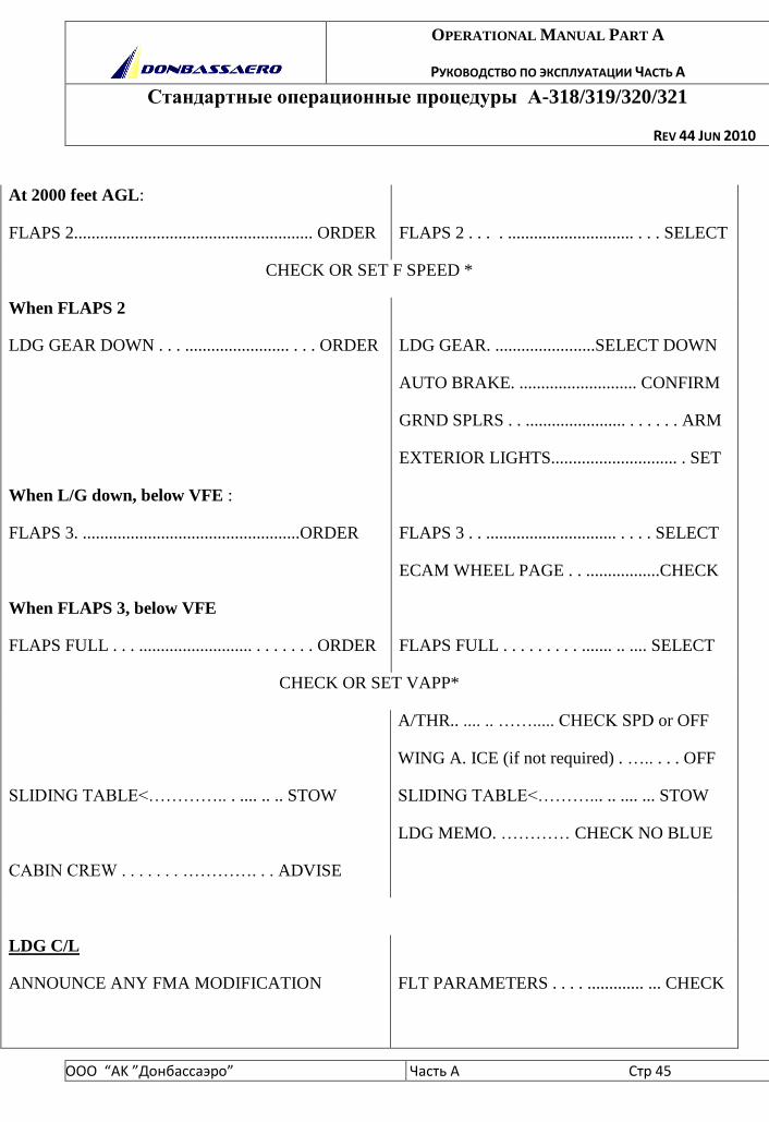
At 2000 feet AGL:
FLAPS 2....................................................... ORDER
FLAPS 2 . . . . ............................. . . . SELECT
CHECK OR SET F SPEED *
When FLAPS 2
LDG GEAR DOWN . . . ........................ . . . ORDER
When L/G down, below VFE :
FLAPS 3. ..................................................ORDER
When FLAPS 3, below VFE
FLAPS FULL . . . .......................... . . . . . . . ORDER
LDG GEAR. .......................SELECT DOWN
AUTO BRAKE. ........................... CONFIRM
GRND SPLRS . . ....................... . . . . . . ARM
EXTERIOR LIGHTS............................. . SET
FLAPS 3 . . .............................. . . . . SELECT
ECAM WHEEL PAGE . . .................CHECK
FLAPS FULL . . . . . . . . . ....... .. .... SELECT
CHECK OR SET VAPP*
SLIDING TABLE<………….. . .... .. .. STOW
CABIN CREW . . . . . . . …………. . . ADVISE
A/THR.. .... .. ……..... CHECK SPD or OFF
WING A. ICE (if not required) . ….. . . . OFF
SLIDING TABLE<………... .. .... ... STOW
LDG MEMO. ………… CHECK NO BLUE
LDG C/L
ANNOUNCE ANY FMA MODIFICATION
FLT PARAMETERS . . . . ............. ... CHECK

OPERATIONAL MANUAL PART A
РУКОВОДСТВО ПО ЭКСПЛУАТАЦИИ ЧАСТЬ А
Стандартные операционные процедуры А-318/319/320/321
REV 44 JUN 2010
ООО “АK ”Донбасcаэро” Часть A Стр 46
At minimum + 100 feet
At minimum :
CONTINUE OR GO-AROUND ...........................
……………………………………..ANNOUNCE
Announce any deviation in excess of :
V/S : 1 000 ft/mn
IAS : speed target + 10 kt ; VAPP - 5 knots
LOC : 1/4 dot LOC
GLIDE: 1 dot GS
PITCH: 2.5° nose down;
10°(7.5° A321) nose up
BANK: 7 °
ONE HUNDRED ABOVE. ..............
……………MONITOR OR ANNOUNCE
MINIMUM .......................................
……………….MONITOR OR ANNOUNCE
* PF if AP is ON, PNF if AP is OFF. The PF may request that this action is
performed by the PNF depending on the situation.
OPERATIONAL MANUAL PART A
РУКОВОДСТВО ПО ЭКСПЛУАТАЦИИ ЧАСТЬ А
Стандартные операционные процедуры А-318/319/320/321
REV 44 JUN 2010
ООО “АK ”Донбасcаэро” Часть A Стр 47
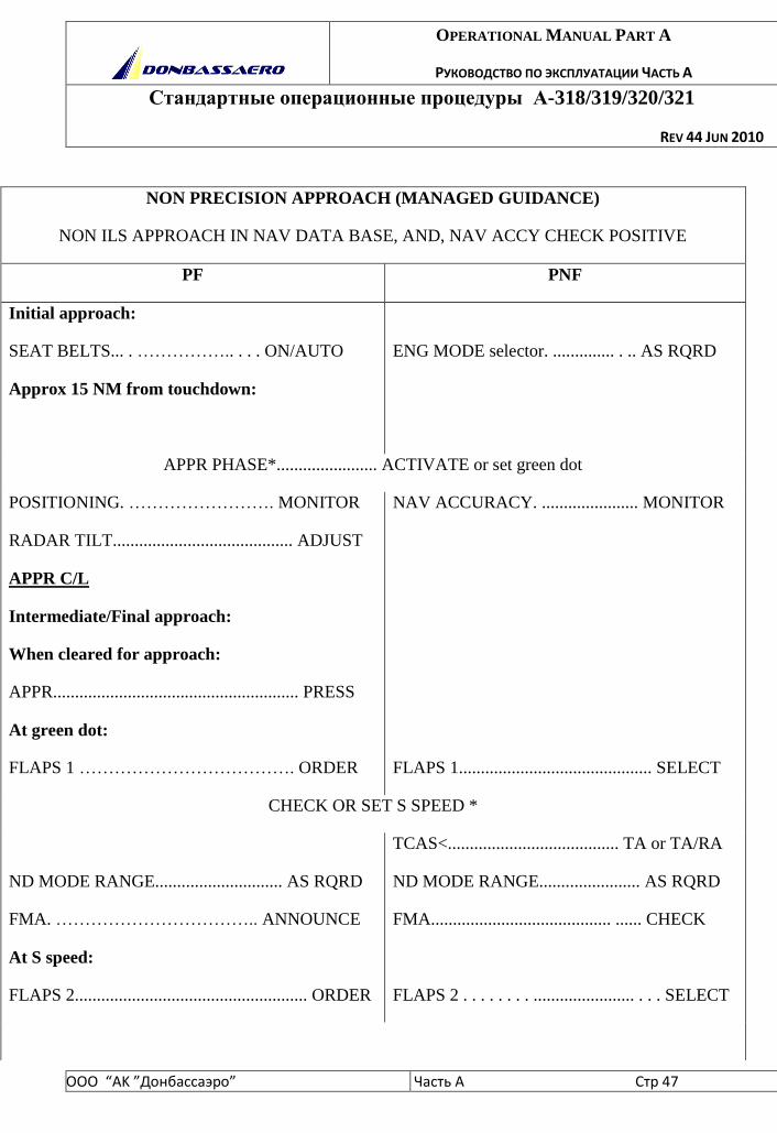
NON PRECISION APPROACH (MANAGED GUIDANCE)
NON ILS APPROACH IN NAV DATA BASE, AND, NAV ACCY CHECK POSITIVE
PF PNF
Initial approach:
SEAT BELTS... . …………….. . . . ON/AUTO
Approx 15 NM from touchdown:
ENG MODE selector. .............. . .. AS RQRD
APPR PHASE*....................... ACTIVATE or set green dot
POSITIONING. ……………………. MONITOR
RADAR TILT......................................... ADJUST
APPR C/L
Intermediate/Final approach:
When cleared for approach:
APPR........................................................ PRESS
At green dot:
FLAPS 1 ………………………………. ORDER
NAV ACCURACY. ...................... MONITOR
FLAPS 1............................................ SELECT
CHECK OR SET S SPEED *
ND MODE RANGE............................. AS RQRD
FMA. …………………………….. ANNOUNCE
At S speed:
FLAPS 2..................................................... ORDER
TCAS<....................................... TA or TA/RA
ND MODE RANGE....................... AS RQRD
FMA......................................... ...... CHECK
FLAPS 2 . . . . . . . . ....................... . . . SELECT
OPERATIONAL MANUAL PART A
РУКОВОДСТВО ПО ЭКСПЛУАТАЦИИ ЧАСТЬ А
Стандартные операционные процедуры А-318/319/320/321
REV 44 JUN 2010
ООО “АK ”Донбасcаэро” Часть A Стр 48
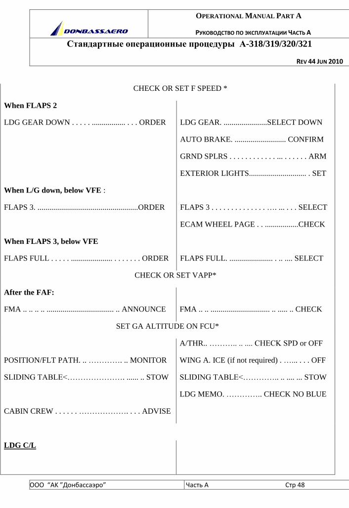
CHECK OR SET F SPEED *
When FLAPS 2
LDG GEAR DOWN . . . . . ................. . . . ORDER
When L/G down, below VFE :
FLAPS 3. ...................................................ORDER
When FLAPS 3, below VFE
FLAPS FULL . . . . . ..................... . . . . . . . ORDER
LDG GEAR. ......................SELECT DOWN
AUTO BRAKE. .......................... CONFIRM
GRND SPLRS . . . . . . . . . . . . ... . . . . . . ARM
EXTERIOR LIGHTS............................. . SET
FLAPS 3 . . . . . . . . . . . . . . …. ... . . . SELECT
ECAM WHEEL PAGE . . .................CHECK
FLAPS FULL. ...................... . .. .... SELECT
CHECK OR SET VAPP*
After the FAF:
FMA .. .. .. .. .................................. .. ANNOUNCE
FMA .. .. .............................. .. ..... .. CHECK
SET GA ALTITUDE ON FCU*
POSITION/FLT PATH. .. …………. .. MONITOR
SLIDING TABLE<…………………. ...... .. STOW
CABIN CREW . . . . . . ………………. . . . ADVISE
A/THR.. ……….. .. .... CHECK SPD or OFF
WING A. ICE (if not required) . …... . . . OFF
SLIDING TABLE<………….. .. .... ... STOW
LDG MEMO. ………….. CHECK NO BLUE
LDG C/L
OPERATIONAL MANUAL PART A
РУКОВОДСТВО ПО ЭКСПЛУАТАЦИИ ЧАСТЬ А
Стандартные операционные процедуры А-318/319/320/321
REV 44 JUN 2010
ООО “АK ”Донбасcаэро” Часть A Стр 49
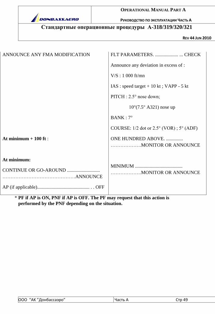
ANNOUNCE ANY FMA MODIFICATION
At minimum + 100 ft :
At minimum:
CONTINUE OR GO-AROUND ...........................
………………………………………ANNOUNCE
AP (if applicable)........................................... . . OFF
FLT PARAMETERS. ................... ... CHECK
Announce any deviation in excess of :
V/S : 1 000 ft/mn
IAS : speed target + 10 kt ; VAPP - 5 kt
PITCH : 2.5° nose down;
10°(7.5° A321) nose up
BANK : 7°
COURSE: 1/2 dot or 2.5° (VOR) ; 5° (ADF)
ONE HUNDRED ABOVE. ..............
……………….MONITOR OR ANNOUNCE
MINIMUM .......................................
……………….MONITOR OR ANNOUNCE
* PF if AP is ON, PNF if AP is OFF. The PF may request that this action is
performed by the PNF depending on the situation.
OPERATIONAL MANUAL PART A
РУКОВОДСТВО ПО ЭКСПЛУАТАЦИИ ЧАСТЬ А
Стандартные операционные процедуры А-318/319/320/321
REV 44 JUN 2010
ООО “АK ”Донбасcаэро” Часть A Стр 50
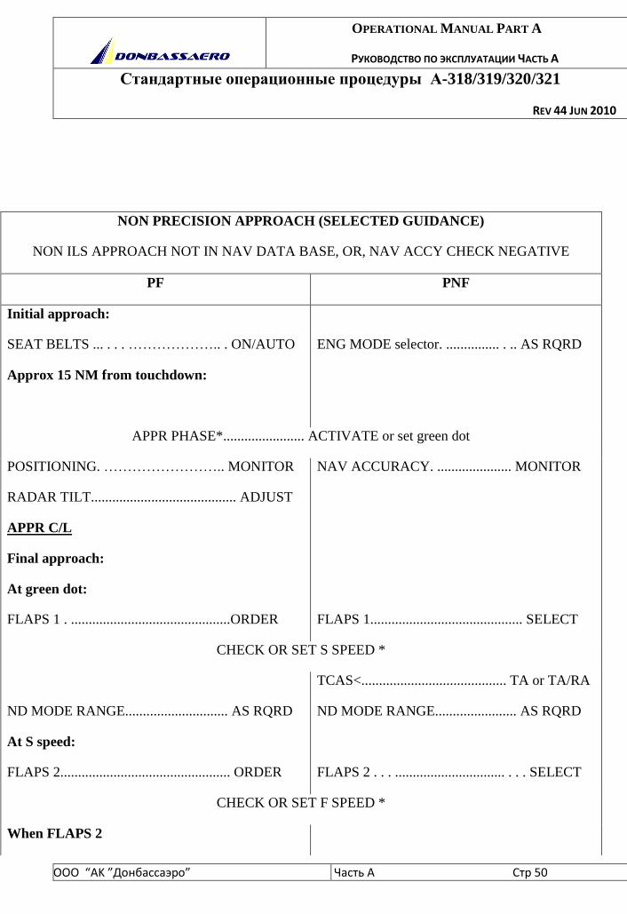
NON PRECISION APPROACH (SELECTED GUIDANCE)
NON ILS APPROACH NOT IN NAV DATA BASE, OR, NAV ACCY CHECK NEGATIVE
PF PNF
Initial approach:
SEAT BELTS ... . . . ……………….. . ON/AUTO
Approx 15 NM from touchdown:
ENG MODE selector. ............... . .. AS RQRD
APPR PHASE*....................... ACTIVATE or set green dot
POSITIONING. …………………….. MONITOR
RADAR TILT......................................... ADJUST
APPR C/L
Final approach:
At green dot:
FLAPS 1 . .............................................ORDER
NAV ACCURACY. ..................... MONITOR
FLAPS 1........................................... SELECT
CHECK OR SET S SPEED *
ND MODE RANGE............................. AS RQRD
At S speed:
FLAPS 2................................................ ORDER
TCAS<......................................... TA or TA/RA
ND MODE RANGE....................... AS RQRD
FLAPS 2 . . . ............................... . . . SELECT
CHECK OR SET F SPEED *
When FLAPS 2
OPERATIONAL MANUAL PART A
РУКОВОДСТВО ПО ЭКСПЛУАТАЦИИ ЧАСТЬ А
Стандартные операционные процедуры А-318/319/320/321
REV 44 JUN 2010
ООО “АK ”Донбасcаэро” Часть A Стр 51
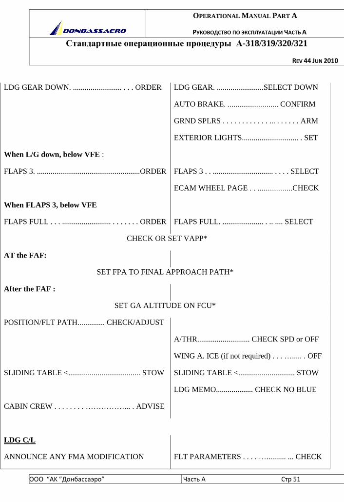
LDG GEAR DOWN. ......................... . . . ORDER
When L/G down, below VFE :
FLAPS 3. .....................................................ORDER
When FLAPS 3, below VFE
FLAPS FULL . . . ......................... . . . . . . . ORDER
LDG GEAR. ........................SELECT DOWN
AUTO BRAKE. .......................... CONFIRM
GRND SPLRS . . . . . . . . . . . . ... . . . . . . ARM
EXTERIOR LIGHTS............................. . SET
FLAPS 3 . . ............................... . . . . SELECT
ECAM WHEEL PAGE . . ..................CHECK
FLAPS FULL. ..................... . .. .... SELECT
CHECK OR SET VAPP*
AT the FAF:
SET FPA TO FINAL APPROACH PATH*
After the FAF :
SET GA ALTITUDE ON FCU*
POSITION/FLT PATH.............. CHECK/ADJUST
SLIDING TABLE <..................................... STOW
CABIN CREW . . . . . . . . ……………... . ADVISE
A/THR........................... CHECK SPD or OFF
WING A. ICE (if not required) . . . …..... . OFF
SLIDING TABLE <............................. STOW
LDG MEMO................... CHECK NO BLUE
LDG C/L
ANNOUNCE ANY FMA MODIFICATION
FLT PARAMETERS . . . . ….......... ... CHECK
OPERATIONAL MANUAL PART A
РУКОВОДСТВО ПО ЭКСПЛУАТАЦИИ ЧАСТЬ А
Стандартные операционные процедуры А-318/319/320/321
REV 44 JUN 2010
ООО “АK ”Донбасcаэро” Часть A Стр 52
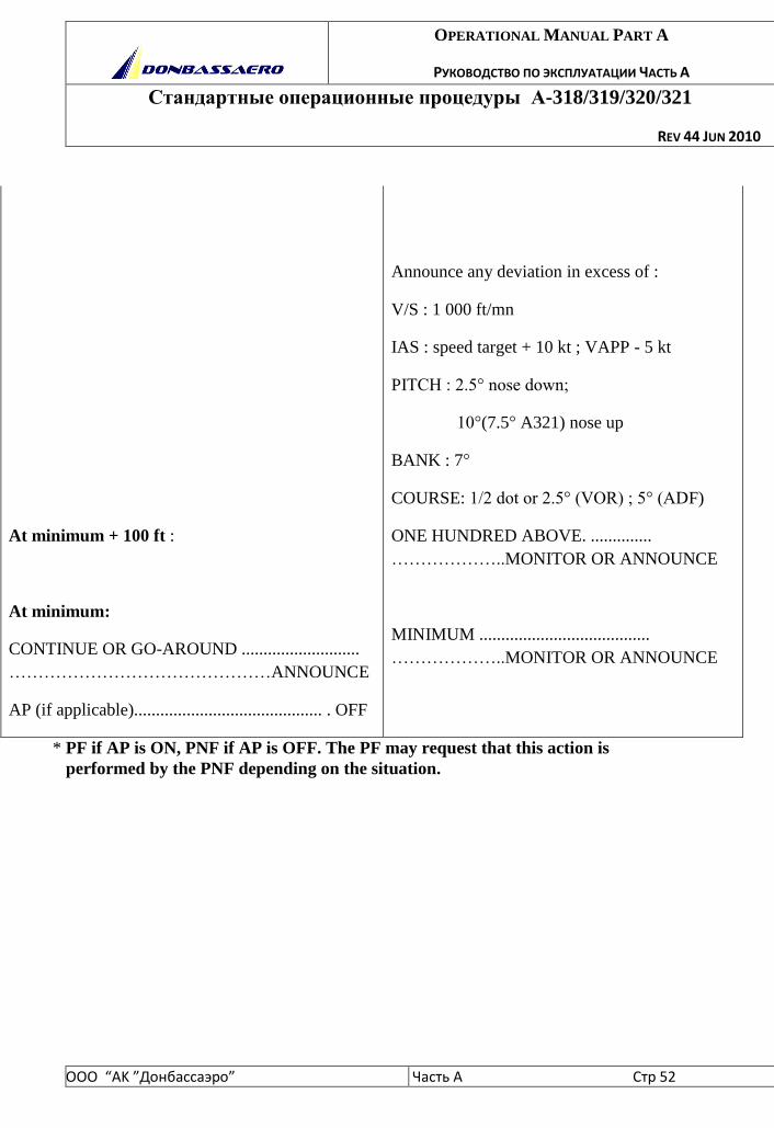
At minimum + 100 ft :
At minimum:
CONTINUE OR GO-AROUND ...........................
………………………………………ANNOUNCE
AP (if applicable)........................................... . OFF
Announce any deviation in excess of :
V/S : 1 000 ft/mn
IAS : speed target + 10 kt ; VAPP - 5 kt
PITCH : 2.5° nose down;
10°(7.5° A321) nose up
BANK : 7°
COURSE: 1/2 dot or 2.5° (VOR) ; 5° (ADF)
ONE HUNDRED ABOVE. ..............
………………..MONITOR OR ANNOUNCE
MINIMUM .......................................
………………..MONITOR OR ANNOUNCE
* PF if AP is ON, PNF if AP is OFF. The PF may request that this action is
performed by the PNF depending on the situation.
OPERATIONAL MANUAL PART A
РУКОВОДСТВО ПО ЭКСПЛУАТАЦИИ ЧАСТЬ А
Стандартные операционные процедуры А-318/319/320/321
REV 44 JUN 2010
ООО “АK ”Донбасcаэро” Часть A Стр 53
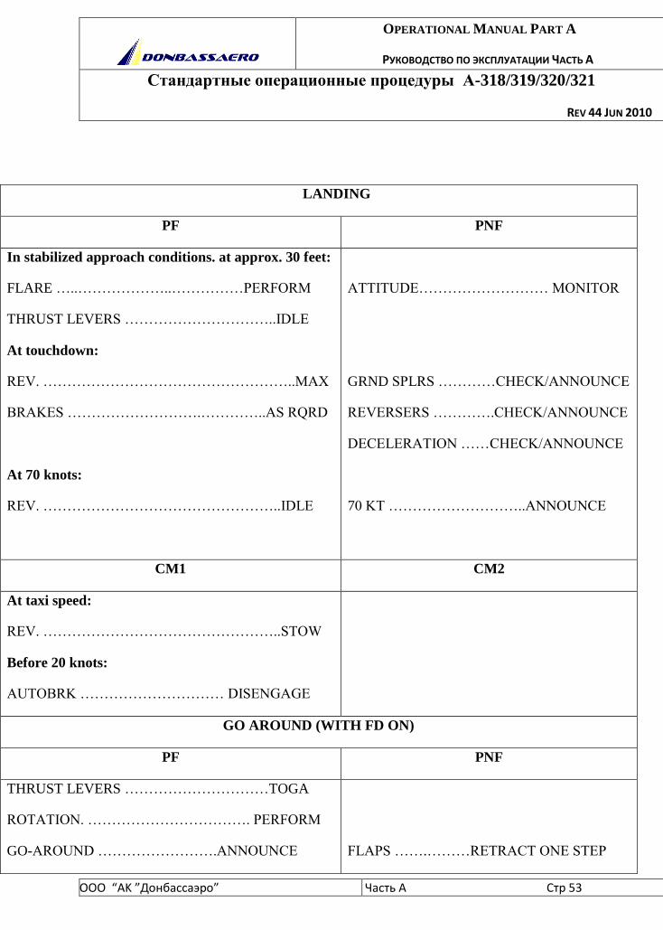
LANDING
PF PNF
In stabilized approach conditions. at approx. 30 feet:
FLARE …..………………..……………PERFORM
THRUST LEVERS …………………………..IDLE
At touchdown:
REV. ……………………………………………..MAX
BRAKES ……………………….…………..AS RQRD
At 70 knots:
REV. …………………………………………..IDLE
ATTITUDE……………………… MONITOR
GRND SPLRS …………CHECK/ANNOUNCE
REVERSERS ………….CHECK/ANNOUNCE
DECELERATION ……CHECK/ANNOUNCE
70 KT ………………………..ANNOUNCE
CM1 CM2
At taxi speed:
REV. …………………………………………..STOW
Before 20 knots:
AUTOBRK ………………………… DISENGAGE
GO AROUND (WITH FD ON)
PF PNF
THRUST LEVERS …………………………TOGA
ROTATION. ……………………………. PERFORM
GO-AROUND …………………….ANNOUNCE
FLAPS …….………RETRACT ONE STEP
OPERATIONAL MANUAL PART A
РУКОВОДСТВО ПО ЭКСПЛУАТАЦИИ ЧАСТЬ А
Стандартные операционные процедуры А-318/319/320/321
REV 44 JUN 2010
ООО “АK ”Донбасcаэро” Часть A Стр 54
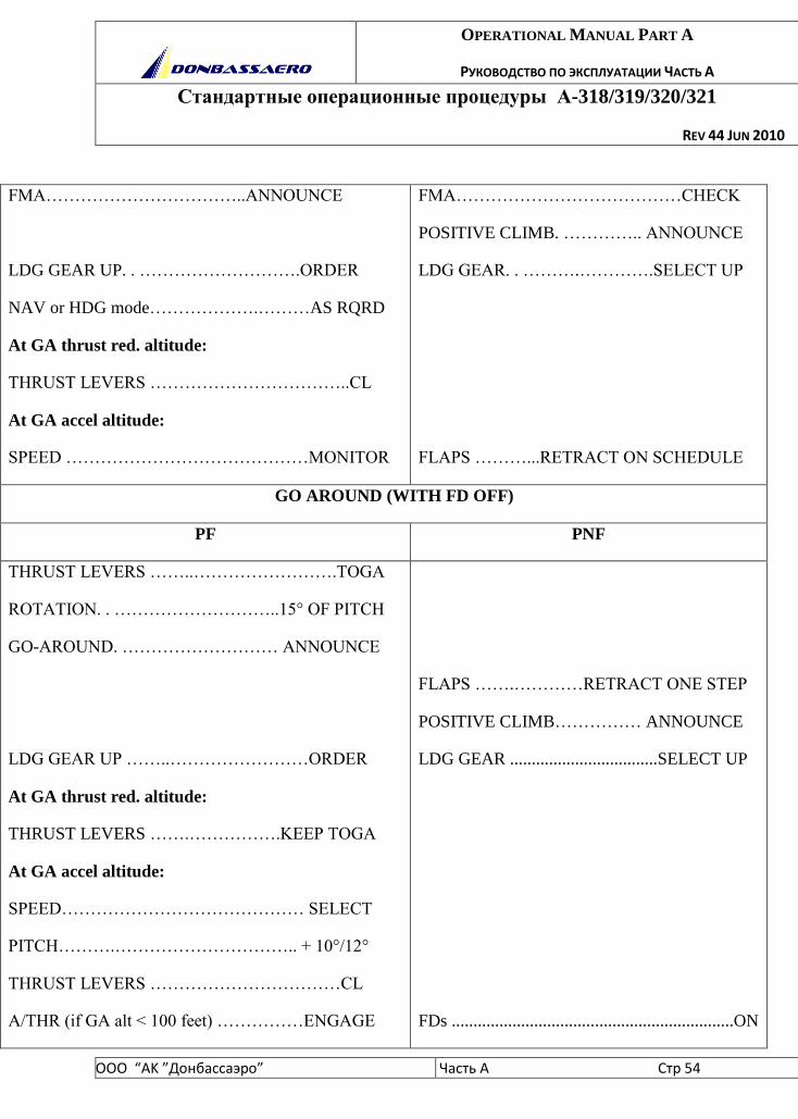
FMA……………………………..ANNOUNCE
LDG GEAR UP. . ……………………….ORDER
NAV or HDG mode……………….………AS RQRD
At GA thrust red. altitude:
THRUST LEVERS ……………………………..CL
At GA accel altitude:
SPEED ……………………………………MONITOR
FMA…………………………………CHECK
POSITIVE CLIMB. ………….. ANNOUNCE
LDG GEAR. . ……….………….SELECT UP
FLAPS ………...RETRACT ON SCHEDULE
GO AROUND (WITH FD OFF)
PF PNF
THRUST LEVERS ……..…………………….TOGA
ROTATION. . ………………………..15° OF PITCH
GO-AROUND. ……………………… ANNOUNCE
LDG GEAR UP ……..……………………ORDER
At GA thrust red. altitude:
THRUST LEVERS …….…………….KEEP TOGA
At GA accel altitude:
SPEED…………………………………… SELECT
PITCH……….………………………….. + 10°/12°
THRUST LEVERS ……………………………CL
A/THR (if GA alt < 100 feet) ……………ENGAGE
FLAPS …….…………RETRACT ONE STEP
POSITIVE CLIMB…………… ANNOUNCE
LDG GEAR ..................................SELECT UP
FDs .................................................................ON
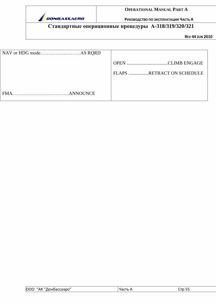
OPERATIONAL MANUAL PART A
РУКОВОДСТВО ПО ЭКСПЛУАТАЦИИ ЧАСТЬ А
Стандартные операционные процедуры А-318/319/320/321
REV 44 JUN 2010
ООО “АK ”Донбасcаэро” Часть A Стр 55
NAV or HDG mode…….……….………AS RQRD
FMA. ……………………………..ANNOUNCE
OPEN ...................................CLIMB ENGAGE
FLAPS .................RETRACT ON SCHEDULE
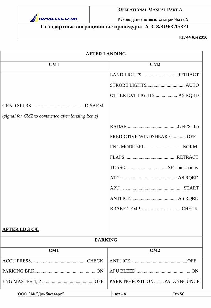
OPERATIONAL MANUAL PART A
РУКОВОДСТВО ПО ЭКСПЛУАТАЦИИ ЧАСТЬ А
Стандартные операционные процедуры А-318/319/320/321
REV 44 JUN 2010
ООО “АK ”Донбасcаэро” Часть A Стр 56
AFTER LANDING
CM1 CM2
GRND SPLRS ............................................DISARM
(signal for CM2 to commence after landing items)
AFTER LDG C/L
LAND LIGHTS .............................RETRACT
STROBE LIGHTS................................ AUTO
OTHER EXT LIGHTS................... AS RQRD
RADAR ..........................................OFF/STBY
PREDICTIVE WINDSHEAR <............ OFF
ENG MODE SEL............................... NORM
FLAPS ...........................................RETRACT
TCAS<. ................................ SET on standby
ATC ................................................AS RQRD
APU……............................................. START
ANTI ICE....................................... AS RQRD
BRAKE TEMP.................................. CHECK
PARKING
CM1 CM2
ACCU PRESS.............................................. CHECK
PARKING BRK................................................... ON
ENG MASTER 1, 2 ............................................OFF
ANTI-ICE ...............................................OFF
APU BLEED ..............................................ON
PARKING POSITION….…PA ANNOUNCE
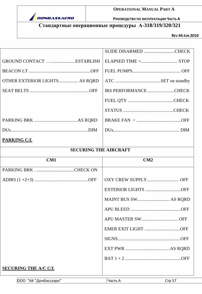
OPERATIONAL MANUAL PART A
РУКОВОДСТВО ПО ЭКСПЛУАТАЦИИ ЧАСТЬ А
Стандартные операционные процедуры А-318/319/320/321
REV 44 JUN 2010
ООО “АK ”Донбасcаэро” Часть A Стр 57
GROUND CONTACT …......................ESTABLISH
BEACON LT ......................................................OFF
OTHER EXTERIOR LIGHTS................. AS RQRD
SEAT BELTS ....................................................OFF
PARKING BRK ......................................AS RQRD
DUs....................................................................DIM
PARKING C/L
SLIDE DISARMED ...........................CHECK
ELAPSED TIME <................................ STOP
FUEL PUMPS.......................................... OFF
ATC ........................................SET on standby
IRS PERFORMANCE .......................CHECK
FUEL QTY ........................................CHECK
STATUS ............................................CHECK
BRAKE FAN < .......................................OFF
DUs.......................................................... DIM
SECURING THE AIRCRAFT
CM1 CM2
PARKING BRK . .................................CHECK ON
ADIRS (1 +2+3) ...............................................OFF
SECURING THE A/C C/L
OXY CREW SUPPLY............................ OFF
EXTERIOR LIGHTS ...............................OFF
MAINT BUS SW............................ AS RQRD
APU BLEED ............................................OFF
APU MASTER SW................................ OFF
EMER EXIT LIGHT ...............................OFF
SIGNS.......................................................OFF
EXT PWR .......................................AS RQRD
BAT 1 + 2 .................................................OFF
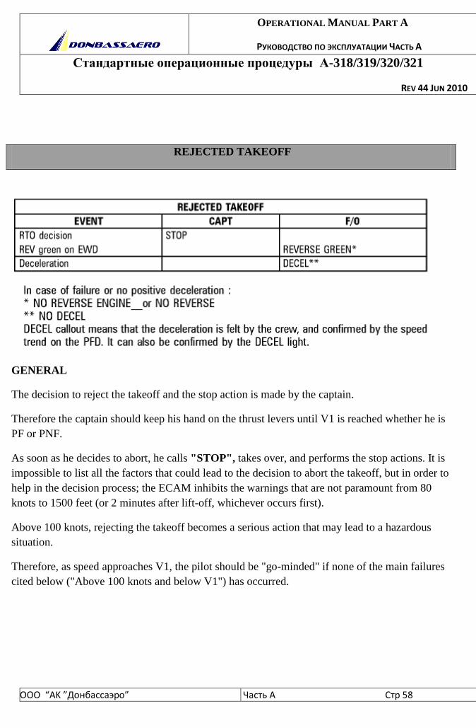
OPERATIONAL MANUAL PART A
РУКОВОДСТВО ПО ЭКСПЛУАТАЦИИ ЧАСТЬ А
Стандартные операционные процедуры А-318/319/320/321
REV 44 JUN 2010
ООО “АK ”Донбасcаэро” Часть A Стр 58
REJECTED TAKEOFF
GENERAL
The decision to reject the takeoff and the stop action is made by the captain.
Therefore the captain should keep his hand on the thrust levers until V1 is reached whether he is
PF or PNF.
As soon as he decides to abort, he calls "STOP", takes over, and performs the stop actions. It is
impossible to list all the factors that could lead to the decision to abort the takeoff, but in order to
help in the decision process; the ECAM inhibits the warnings that are not paramount from 80
knots to 1500 feet (or 2 minutes after lift-off, whichever occurs first).
Above 100 knots, rejecting the takeoff becomes a serious action that may lead to a hazardous
situation.
Therefore, as speed approaches V1, the pilot should be "go-minded" if none of the main failures
cited below ("Above 100 knots and below V1") has occurred.
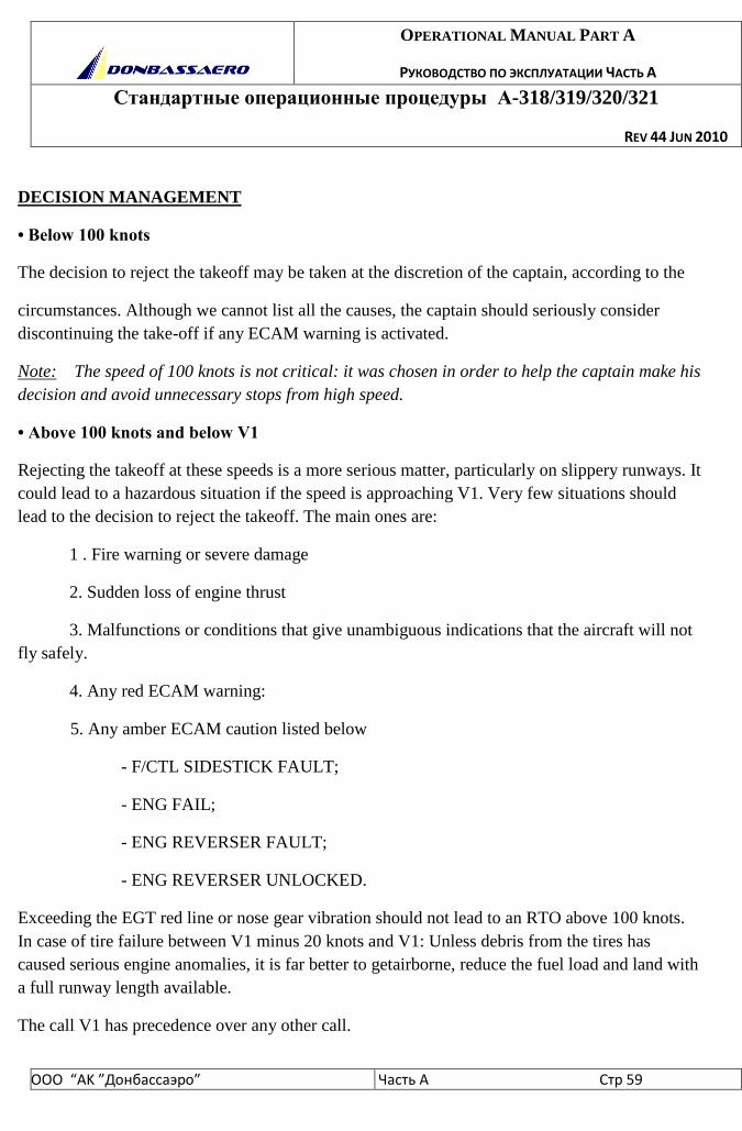
OPERATIONAL MANUAL PART A
РУКОВОДСТВО ПО ЭКСПЛУАТАЦИИ ЧАСТЬ А
Стандартные операционные процедуры А-318/319/320/321
REV 44 JUN 2010
ООО “АK ”Донбасcаэро” Часть A Стр 59
DECISION MANAGEMENT
• Below 100 knots
The decision to reject the takeoff may be taken at the discretion of the captain, according to the
circumstances. Although we cannot list all the causes, the captain should seriously consider
discontinuing the take-off if any ECAM warning is activated.
Note: The speed of 100 knots is not critical: it was chosen in order to help the captain make his
decision and avoid unnecessary stops from high speed.
• Above 100 knots and below V1
Rejecting the takeoff at these speeds is a more serious matter, particularly on slippery runways. It
could lead to a hazardous situation if the speed is approaching V1. Very few situations should
lead to the decision to reject the takeoff. The main ones are:
1 . Fire warning or severe damage
2. Sudden loss of engine thrust
3. Malfunctions or conditions that give unambiguous indications that the aircraft will not
fly safely.
4. Any red ECAM warning:
5. Any amber ECAM caution listed below
- F/CTL SIDESTICK FAULT;
- ENG FAIL;
- ENG REVERSER FAULT;
- ENG REVERSER UNLOCKED.
Exceeding the EGT red line or nose gear vibration should not lead to an RTO above 100 knots.
In case of tire failure between V1 minus 20 knots and V1: Unless debris from the tires has
caused serious engine anomalies, it is far better to getairborne, reduce the fuel load and land with
a full runway length available.
The call V1 has precedence over any other call.
OPERATIONAL MANUAL PART A
РУКОВОДСТВО ПО ЭКСПЛУАТАЦИИ ЧАСТЬ А
Стандартные операционные процедуры А-318/319/320/321
REV 44 JUN 2010
ООО “АK ”Донбасcаэро” Часть A Стр 60
• Above V1
Take-off must be continued because it may not be possible to stop the aircraft on the remaining
runway.
REVERSERS: Full reverse may be used until a complete stop. But, if there is enough runway
available at the end of the deceleration, it is preferable to reduce reverse thrust when passing 70
knots.
OPERATIONAL MANUAL PART A
РУКОВОДСТВО ПО ЭКСПЛУАТАЦИИ ЧАСТЬ А
Стандартные операционные процедуры А-318/319/320/321
REV 44 JUN 2010
ООО “АK ”Донбасcаэро” Часть A Стр 61
OPERATIONAL MANUAL PART A
РУКОВОДСТВО ПО ЭКСПЛУАТАЦИИ ЧАСТЬ А
Стандартные операционные процедуры А-318/319/320/321
REV 44 JUN 2010
ООО “АK ”Донбасcаэро” Часть A Стр 62
ENG FAILURE AFTER V1
- If an engine fails after the aircraft passes V1, the takeoff must be continued.
- Use rudder conventionally to stay on the runway centerline.
- At VR, rotate the aircraft smoothly using a continuous pitch rate to a pitch attitude of 12.5
degrees. After liftoff, follow the Speed Reference System (SRS).
- When airborne with a positive rate of climb, select the landing gear up.
- Use rudder to prevent yaw. Shortly after lift-off, β target will appear. Adjust rudder position to
zero the . β target. Control heading conventionally with bank, keeping the β target at zero with
rudder.
- Consider the use of TOGA thrust.
- Consider the use of autopilot.
- At 400 feet minimum, apply the ECAM procedure
- At acceleration height, level off and allow the speed to increase.
• At F speed select CONF 1.
• At S speed select CONF 0.
- When the flap handle is at zero, . target reverts to side-slip indication. Center the sideslip
indication conventionally.
- At green dot speed (engine-out operating speed in clean configuration) resume the climb using
maximum continuous thrust and maintain green dot speed. (If already in the FLX/MCT gate,
move to CL and back to MCT).
- MAXIMUM TAKEOFF THRUST IS ONLY ALLOWED FOR 10 MINUTES.
OPERATIONAL MANUAL PART A
РУКОВОДСТВО ПО ЭКСПЛУАТАЦИИ ЧАСТЬ А
Стандартные операционные процедуры А-318/319/320/321
REV 44 JUN 2010
ООО “АK ”Донбасcаэро” Часть A Стр 63
ENGINE FAILURE DURING INITIAL CLIMB-OUT
- Proceed as above. However, if the failure occurs above V2 maintain the SRS commanded
attitude (or the speed reached after recovery). In any case, the minimum speed must be equal to
V2.
APPROACH WITH ONE ENG INOP
For performance reasons, do not extend flap full until established on a final descent to landing.
If a level off is expected during final approach, perform the approach and landing in CONF 3.
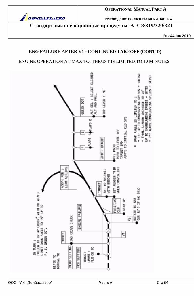
OPERATIONAL MANUAL PART A
РУКОВОДСТВО ПО ЭКСПЛУАТАЦИИ ЧАСТЬ А
Стандартные операционные процедуры А-318/319/320/321
REV 44 JUN 2010
ООО “АK ”Донбасcаэро” Часть A Стр 64
ENG FAILURE AFTER V1 - CONTINUED TAKEOFF (CONT'D)
ENGINE OPERATION AT MAX TO. THRUST IS LIMITED TO 10 MINUTES
OPERATIONAL MANUAL PART A
РУКОВОДСТВО ПО ЭКСПЛУАТАЦИИ ЧАСТЬ А
Стандартные операционные процедуры А-318/319/320/321
REV 44 JUN 2010
ООО “АK ”Донбасcаэро” Часть A Стр 65
FLIGHT PREPARATION FOR CAT II / III OPERATIONS.
In addition to normal flight preparation, the following planning and preparation must be
performed when CAT II or CAT III approaches are envisaged.
-Review NOTAMS to make sure that the destination airport still meets visual or non-visual CAT
Il or CAT III requirements:
- Runway and approach lighting,
- Radio navaid availability,
- RVR equipment availability, etc
- Aircraft status: check that required equipment for CAT II or CAT III approaches are operative.
The required equipment list is given in the FCOM and in the AFM.
When the aircraft log book is available, confirm that no write-up during previous flights affects
equipment required for CAT II / CAT III. A maintenance release statement for CAT II / CAT Ill
may be indicated in the log book according to «Donbassaero» policy.
- Crew qualification and currency must be reviewed (both CAPT and F/0 must be qualified and
current).
- Weather information: check that the weather forecast at destination is within airline and crew
operating minima. If the forecast is below CAT I minima, verify that alternate weather forecasts
are appropriate to the available approach means and at least equal or better than CAT I minima.
- Fuel planning: additional extra fuel should be considered for possible approach delays.
APPROACH PREPARATION
Aircraft Status
Check on ECAM STATUS page that the required landing capability is available. Although it is
not required to check equipment that is not monitored by the system, if any of this equipment is
seen inoperative (flag), the landing capability will be reduced.
Check AUTOLAND WARNING light.

OPERATIONAL MANUAL PART A
РУКОВОДСТВО ПО ЭКСПЛУАТАЦИИ ЧАСТЬ А
Стандартные операционные процедуры А-318/319/320/321
REV 44 JUN 2010
ООО “АK ”Донбасcаэро” Часть A Стр 66
Weather
Check weather conditions at destination and at alternates. Required RVR values must
be available for CAT II/III approaches. The selected alternate must have weather conditions
equal to or better than CAT I.
Approach ban
Policy regarding an approach ban may differ from country to country. Usually the final
approach segment may not be continued beyond the OM or equivalent DME distance if
the reported RVR is below the published minima for the required transmissometers.
After OM or equivalent, if RVR becomes lower than the minima, the approach may be
continued.
ATC calls
Unless LVP are reported active by ATIS, clearance to carry out a CAT II or CAT III
approach must be requested from ATC, who will check the status of the ILS and lighting and
protect the sensitive areas from incursion by aircraft or vehicles. Such an approach may not be
undertaken until the clearance has been received. Before the outer marker, the required RVR
values should be transmitted.
Seat position
The correct seat adjustment is essential in order to take full advantage of the visibility
over the nose. The seat is correctly adjusted when the pilots eyes are in line with the red and
white balls located above the glareshield.
Use of landing lights
At night in low visibility conditions, landing lights can be detrimental to the
acquisition of visual references. Reflected light from water droplets or snow may actually reduce
visibility. Landing lights would therefore not normally be used in CAT ll or CAT III weather
conditions.

OPERATIONAL MANUAL PART A
РУКОВОДСТВО ПО ЭКСПЛУАТАЦИИ ЧАСТЬ А
Стандартные операционные процедуры А-318/319/320/321
REV 44 JUN 2010
ООО “АK ”Донбасcаэро” Часть A Стр 67
CAT II or CAT III crew briefing
The briefing should include the normal items as for any IFR arrival and in addition
the following subjects should be covered prior to the first approach:
−destination and alternate weather,
−airfield and runway operational status CAT II / CAT III, etc.
−aircraft systems status and capacity,
−brief review of task sharing,
−review approach procedure (stabilized or decelerated),
−review applicable minima (performance page), go-around procedure, ATC calls,
−brief review of procedure in case of malfunction below 1000ft,
−optimum seat position and reminder to set cockpit lights when appropriate
APPROACH PROCEDURES
The procedures given in FCOM for CAT II and CAT III approaches make the best
use of the automatic system of the aircraft.
TASK SHARING
CM1 and CM2 task sharing must be use for a CAT II/III approaches. The task sharing proposed
here below is one example of how to conduct a CAT II/III approach. Before commence the
approach the AFM procedures should be observed.
For the “Donbassaero” the required task sharing for a CAT II / CAT III
approach is that CM1 is PF and CM2 is PNF.
The workload is distributed in such a way that the CM1 primary tasks are supervising
and decision making, and the CM2 primary task is monitoring operation of the
automatic system.
In summary the tasks are shared as follows:
OPERATIONAL MANUAL PART A
РУКОВОДСТВО ПО ЭКСПЛУАТАЦИИ ЧАСТЬ А
Стандартные операционные процедуры А-318/319/320/321
REV 44 JUN 2010
ООО “АK ”Донбасcаэро” Часть A Стр 68
CM1 - has hands on controls and thrust levers throughout the approach, landing or go-around;
- makes FCU selections (if any);
- takes manual control in the event of AP disconnection ;
- monitors flight instruments.
Approaching DH:
- starts to look for visual references, progressively increasing external scanning as DH is
approached. If no DH procedure is used, the PF will nevertheless look for visual references.
At or before DH (if his decision is to continue):
- calls CONTINUE " ;
- scans mostly head-up to monitor the flight path and flare(in CAT II or CAT III A) or the
position on the runway (in CAT IIIB) by visual references;
- monitors thrust reduction , at "RETARD" call-out, sets thrust levers to idle ;
- selects and controls reverse thrust;
- disengages autopilot when taxi speed is reached.
CM2 - monitors flight instruments head-down throughout approach, go-around or landing until
rollout is completed;
- calls any deviation or failure warning ;
- calls barometric heights as required, and monitors auto call-out or calls radio heights including
"100 above" ;
- monitors FMA and calls mode changes as required.
At DH (identified by aural and visual warning):
- if decision is not announced by CM1, calls "MINIMUM";
- if no response from CM1, initiates a go-around.
CM1 - if no failure by AH, calls "CONTINUE ";
- monitors flare by flight instruments;
OPERATIONAL MANUAL PART A
РУКОВОДСТВО ПО ЭКСПЛУАТАЦИИ ЧАСТЬ А
Стандартные операционные процедуры А-318/319/320/321
REV 44 JUN 2010
ООО “АK ”Донбасcаэро” Часть A Стр 69
- monitors lateral guidance during flare by yaw bar on PDF ;
- monitors automatic ground roll by scanning alternately instruments and external references.
IF DECISION IS TO GO AROUND:
CM1 - calls "GO-AROUND – FLAPS";
- initiates go-around by setting thrust levers to TOGA;
- monitors rotation on PFD;
- checks positive climb (V/S and RA);
- commands configuration changes.
CM2 - Standard Operating Procedures
VISUAL REFERENCES
Operations with DH
It should be stressed that the DH is the lower limit of the decision zone during
which, in limiting conditions, the CM1 will be assessing the visual references. CM1
should come to this zone prepared for a go around but with no pre-established
judgement. CM1 should make a decision according to the quality of the approach
and the way the visual references develop as DH is approached.
a) CAT II Operations
In CAT II operations the conditions required at DH to continue the approach are that
the visual references should be adequate to monitor the continued approach and
landing, and that the flight path should be acceptable. If both these conditions are
not satisfied, it is mandatory to initiate a go around.
OPERATIONAL MANUAL PART A
РУКОВОДСТВО ПО ЭКСПЛУАТАЦИИ ЧАСТЬ А
Стандартные операционные процедуры А-318/319/320/321
REV 44 JUN 2010
ООО “АK ”Донбасcаэро” Часть A Стр 70
The visual references required at DH in CAT II operations to continue the approach
may be any of the following:
−a segment of the approach light system,
−the runway threshold,
−the touchdown zone.
b) CAT III Operations
In CAT III operations with DH, the condition required at DH is that there should be
visual references, which confirm that the aircraft is over the touchdown zone. Go
around is mandatory if the visual references do not confirm this.
CAT III without DH
For this category of operation, the decision to continue does not depend on visual
references, even though a minimum RVR is specified (see OPERATING MINIMA).
It is nevertheless good airmanship to confirm aircraft position with available visual
references. However, the decision depends only on the operational status of the
aircraft and ground equipment. If a failure occurs prior to reaching the AH, a
go-around will be made. A go around must nevertheless be performed if the
autoland warning is triggered below AH.
LOSS OF VISUAL REFERENCES
A. Operations with DH - before touchdown
If the decision to continue has been made and the visual references subsequently
become insufficient (for the appropriate category), or the flight path deviates
unacceptably, a go-around must be initiated (a go around initiated below the MABH,
whether auto or manual, may result in ground contact).

OPERATIONAL MANUAL PART A
РУКОВОДСТВО ПО ЭКСПЛУАТАЦИИ ЧАСТЬ А
Стандартные операционные процедуры А-318/319/320/321
REV 44 JUN 2010
ООО “АK ”Донбасcаэро” Часть A Стр 71
NOTE: If the touchdown occurs after GA is engaged the AP remains engaged in
that mode, and ATHR remains in TOGA. Ground spoilers and auto-brake are inhibited.
B. Operations with and without DH - after touchdown
If the visual references are lost after touchdown, a go-around should not be attempted.
The rollout should be continued with AP in ROLLOUT mode down to taxi speed.
FLIGHT PARAMETERS DEVIATION CALLS
These calls would normally be made by the PNF and acknowledged by the PF.
However, any crewmember that sees a deviation outside the above limits should make the
appropriate call.
If any of these limits are exceeded approaching DH, a go-around should be
considered.
FAILURES AND ASSOCIATED ACTIONS
GENERAL
In general there are three possible responses to the failure of any system, instrument or element
during the approach.
−CONTINUE the approach to the planned minima.
−REVERT to higher minima and proceed to a new DH(above 1000ft).
−GO AROUND and reassess the capability.
The nature of the failure and the point of its occurrence will determine which response is
appropriate.
As a general rule, if a failure occurs above 1000ft AGL the approach may be
continued reverting to a higher DH, providing the appropriate conditions are met
(refer to "DOWNGRADING CONDITION").
Below 1000ft (and down to AH when in CAT III DUAL) the occurrence of any failure
OPERATIONAL MANUAL PART A
РУКОВОДСТВО ПО ЭКСПЛУАТАЦИИ ЧАСТЬ А
Стандартные операционные процедуры А-318/319/320/321
REV 44 JUN 2010
ООО “АK ”Донбасcаэро” Часть A Стр 72
implies a go-around, and a reassessment of the system capability. Another approach may then be
undertaken to the appropriate minima for the given aircraft status.
It has been considered that below 1000ft, not enough time is available for the crew
to perform the necessary switching, to check system configuration and limitations and brief for
minima.
In CAT III DUAL, in general, a single failure (for example one AP failure or one engine failure)
below AH does not necessitate a go-around.
But a go-around is required if the autoland warning is triggered.
ABNORMAL PROCEDURES
The required procedures following failures during CAT II or CAT III approaches are provided in
the Approved Flight Manual (AFM). These procedures have been established and approved
during the aircraft CAT Il / CAT III certification.
It has been found that a simplification of the AFM abnormal procedures was desirable for actual
operation. Therefore, these simplified abnormal procedures, which are necessarily more
conservative, are published in the FCOM. Operators may always refer to AFM for detailed
information if they want to develop their own abnormal procedures.
The abnormal procedures can be classified into two groups
1. Failures leading to a downgrading of capability as displayed on FMA and
ECAM with an associated specific audio warning (triple click).
2. Failures that do not trigger a downgrading of capability but are signaled by
other effects (Flag, ECAM warning, amber caution and associated audio warnings).
It should be noted that some failures might trigger ECAM warnings, cautions and a
downgrading of capability.
The FCOM describes what should be the crew responses to failures in function to
the height.
OPERATIONAL MANUAL PART A
РУКОВОДСТВО ПО ЭКСПЛУАТАЦИИ ЧАСТЬ А
Стандартные операционные процедуры А-318/319/320/321
REV 44 JUN 2010
ООО “АK ”Донбасcаэро” Часть A Стр 73
Above 1000ft:
* DOWNGRADING CONDITIONS
a) Downgrading from CAT 3 to CAT 2 is permitted only if
−ECAM actions are completed,
−RVR is at least equal to CAT II minima,
−Briefing is amended to include CAT II procedure and DH.
−Decision to downgrade is completed above 1000ft AGL,
b) Downgrading from CAT 2 to CAT 1 permitted only if
−ECAM actions are completed,
−at least one FD is available,
−RVR is at least equal to CAT I minima,
−briefing is amended to include CAT 1 procedure and DH.
−the decision to downgrade is completed above 1000ft AGL,
Note: switching from one AP to another before 1000ft AGL is permitted.
Below 1000ft and above DH (for CAT 2 or CAT 3 SINGLE) or above AH (for CAT 3
DUAL) a go-around must be performed in case of:
−ALPHA FLOOR activation,
−loss of AP (cavalry charge),
−downgrading of capability (triple click),
−amber caution (single chime),
−engine failure.
At 350ft* RA
OPERATIONAL MANUAL PART A
РУКОВОДСТВО ПО ЭКСПЛУАТАЦИИ ЧАСТЬ А
Стандартные операционные процедуры А-318/319/320/321
REV 44 JUN 2010
ООО “АK ”Донбасcаэро” Часть A Стр 74
LAND must be displayed on FMA and runway course must be checked. If runway course is
incorrect or LAND does not appear, a go-around must be performed. If conditions permit, a
CAT II approach with AP disconnection no later than 80ft may be performed.
LAND is displayed if LOC and GS track modes are active and at least one RA is available.
These conditions need to be obtained no later than 350ft AGL to allow a satisfactory automatic
landing.
* Depending on terrain profile before the runway LAND mode may appear at lower
height. This can be acceptable provided it has been demonstrated that automatic
landing is satisfactory.
At 200ft RA and below
Any AUTOLAND warning requires an immediate go-around.
If visual references are sufficient and a manual landing is possible, the PF may decide to land
manually.
At flare height
If FLARE does not come up on FMA, a go-around must be performed.
If visual references are sufficient and a manual landing is possible, the PF may decide to
complete the landing.
After touchdown
In case of anti-skid or nose wheel steering failure, disconnect AP and take manualcontrol. If
automatic rollout control is not satisfactory, disconnect the AP immediately.
![DONBASS 513 - NUMAX · 2019-04-17 · Soberbio» Luis Martínez, EL MUNDO. DONBASS [Sergei Loznitsa, 2018] “A estrutura de Donbass inspírase en Eisenstein e ... Dali, Duchamp](https://img.pdfslide.tips/doc/110x75/5f7b2b2e3566cf5f2452c592/donbass-513-numax-2019-04-17-soberbio-luis-martnez-el-mundo-donbass-sergei.jpg)

![Ein Projektbericht von: Frank Sommer - a320-project.de · [Buttons.Feelthere A320 CFM Condor VA] // Viewmode 37=P3000,1,C65567,0 38=P3001,1,C65567,0 . Projekt Airbus A320 das virtuelle](https://img.pdfslide.tips/doc/110x75/5b14290d7f8b9a437c8b9d2f/ein-projektbericht-von-frank-sommer-a320-buttonsfeelthere-a320-cfm-condor.jpg)