Embed Size (px)
Citation preview

Dr. LI, Chao
Lambeth Associates Ltd. 17-September-2014
Email: [email protected]
HKIE Geotechnical Division Seminar:
Common Pitfalls and Important Points to Note in Using Geotechnical Computer
Programs (Geotechnical Computer Program Users Group Meeting No. 2)
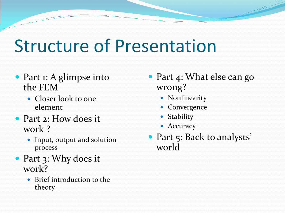
Structure of Presentation
Part 4: What else can go wrong? Nonlinearity
Convergence
Stability
Accuracy
Part 5: Back to analysts’ world
Part 1: A glimpse into the FEM Closer look to one
element
Part 2: How does it work ? Input, output and solution
process
Part 3: Why does it work? Brief introduction to the
theory

Part 1: A Glimpse into the Finite Element Method

An airplane
A finite
element
model of an
airplane
Illustration 1
Are they
equivalent?

Illustration 2: Hierarchy in FEM Simulation
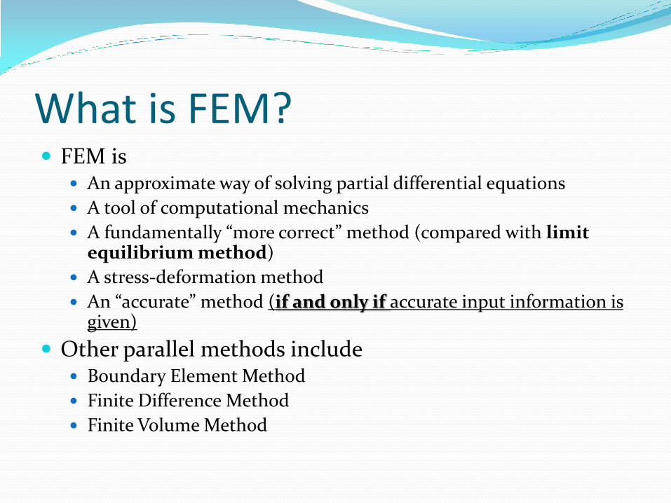
What is FEM? FEM is
An approximate way of solving partial differential equations
A tool of computational mechanics
A fundamentally “more correct” method (compared with limit equilibrium method)
A stress-deformation method
An “accurate” method (if and only if accurate input information is given)
Other parallel methods include Boundary Element Method
Finite Difference Method
Finite Volume Method
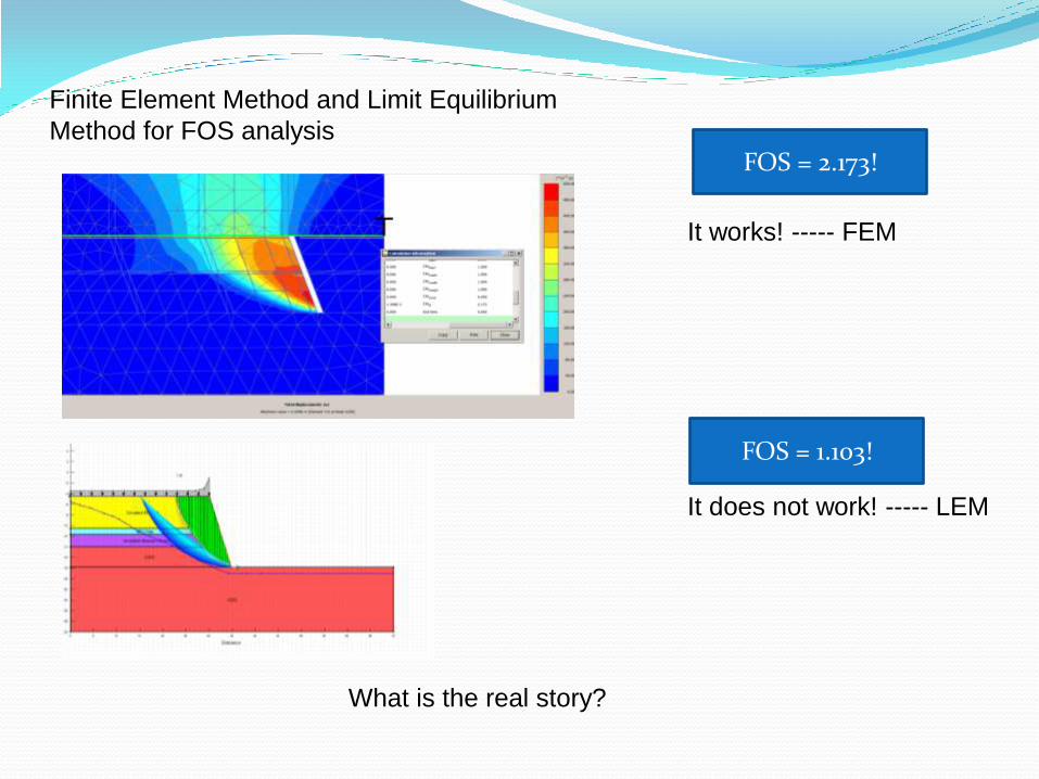
It works! ----- FEM
It does not work! ----- LEM
FOS = 2.173!
FOS = 1.103!
Finite Element Method and Limit Equilibrium
Method for FOS analysis
What is the real story?

Question: What is an Element?

An Element and the Interface What is an “Element”?
A division of the domain. An atom. The smallest mechanical entity, where a constitutive relationship can be directly applied. An Element is a smallest mesh!
Types of elements 1D, 2D or 3D elements (A FE program has a library of elements)
Solid elements, shell elements, beam elements, etc
Connections between elements The “connection” between finite elements shall be clearly
understood (particularly true when the connection is between different type of elements)
The interface behavior shall be clearly understood (sliding, friction, contact, separation etc)

The FEM Program Input (Pre-processing)
Solution (Core [Black Box])
Output (Post-processing)
User
Developer
Part 2: How Does It Work ?
More mutual understanding?

Input Geometry
Loadings and boundary conditions
Loadings include body force and surface force
Surface force is one kind of boundary condition
Material properties
Solution control parameters
The problem shall be “well-defined” !

Are they equivalent??
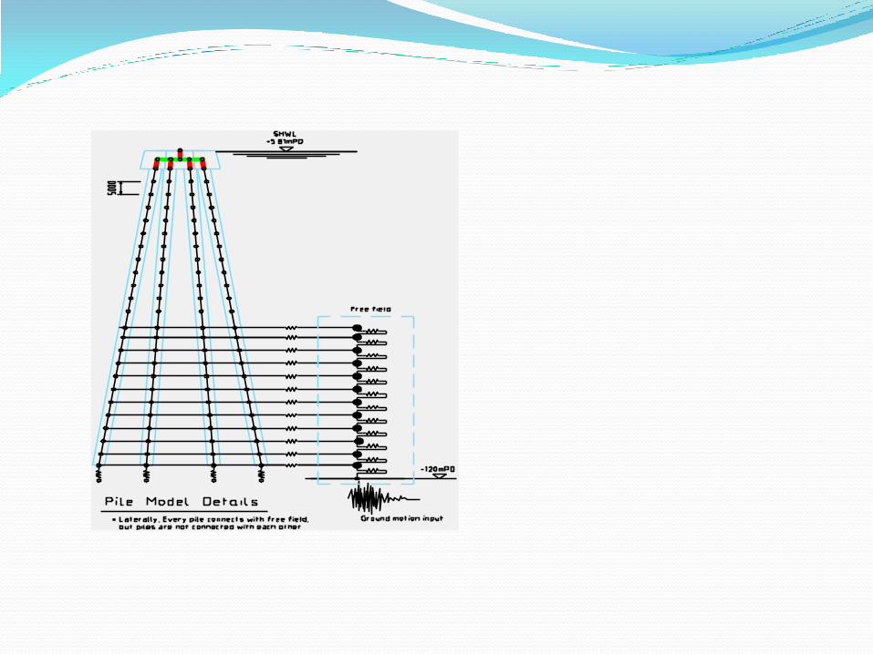
Pile Modeling:
“embedded pile”, “beam” or solid element?

How about this?

Simplifications Can Lead to Troubles
The following are common in design but “new” or “difficult” to finite element program
Slip surface
Sub-grade modulus
Poisson’s ratio =0.5 for saturated clays
Factored strength and modulus parameters
Point loads
……
Don’t take your design-world experience for granted. Examine your assumptions.
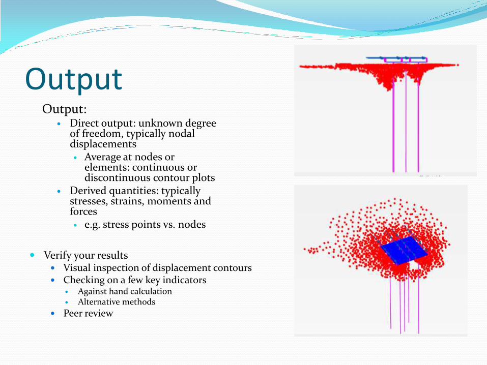
Output Output:
Direct output: unknown degree of freedom, typically nodal displacements Average at nodes or
elements: continuous or discontinuous contour plots
Derived quantities: typically stresses, strains, moments and forces e.g. stress points vs. nodes
Verify your results Visual inspection of displacement contours Checking on a few key indicators
Against hand calculation Alternative methods
Peer review

Solution Process Solution algorithm
Implicit algorithm
ANSYS, ABAQUS-Implicit, SAP2000, PLAXIS
Explicit algorithm
LS-DYNA, ABAQUS-Explicit

Solution Process for Implicit Method Time/Load Step
Iteration loop
Assemble force vector and stiffness matrix
Loop over element
Loop over Gauss integration point
Call material subroutine
End loop
End loop
Next Time/Load Step

Basis of Theoretical Background Background of FEM
The link between FEM, Mechanics (continuum mechanics) and material science (constitutive laws)
Governing equations Balance laws
Balance of mass
Balance of linear momentum
Stress-strain relationship Linear
Nonlinear
Part 3: Why Does It Work?

Governing Equations Strong Form
Weak Form
Matrix Form
} {} {} { FormMatrixFormWeakFormStrong
0, iiij f
dhwdfwdw iiiiijji ,
BDBdKwhere
FKd
,
Discretion Error Hidden Assumption on Problem Continuity
What engineers normally know
What the software know

Part 4: What Else Can Go Wrong?
Nonlinearity
Convergence
Stability
Accuracy
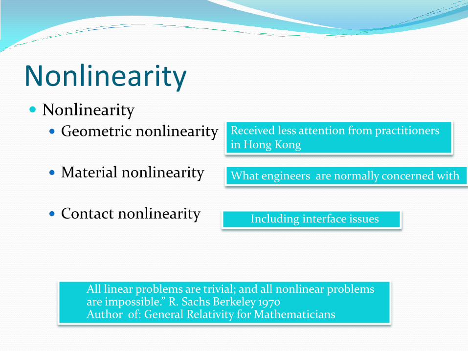
Nonlinearity Nonlinearity
Geometric nonlinearity
Material nonlinearity
Contact nonlinearity
What engineers are normally concerned with
Including interface issues
Received less attention from practitioners in Hong Kong
All linear problems are trivial; and all nonlinear problems are impossible.” R. Sachs Berkeley 1970 Author of: General Relativity for Mathematicians

Convergence Convergence
Mesh independent solution (coarse mesh vs. fine mesh)
Increase of the number of loading step or time step
General criterion The smaller the mesh, the accurate the solution (!not
always true!)
The smaller the time step, the accurate the solution (!not always true!)

Stability An “insensitivity” to small perturbations
Perturbations are modeling errors of systems, environment, noise
For dynamic analysis: “stability requirement” implies a limitation on time step and element size
Stability of solutions to discrete equations
Stability of time integration procedures
Material stability (softening)
Developers
Users
Developers
Users

Accuracy First order accurate
Second order accurate
e/accuracyconvergenc of rate ,||
stablenally unconditio 1 ,
)()1(
)()1(
kece
AeAe
kii
ii
Mathematical form

Why FEM is NOT accurate for geotechnical problems
Uncertainty in material behavior
One-phase material vs. two-phase material
Limited geological information
Derivation of parameters based on empirical rules
Highly nonlinearity (3 types!)
Uncertainties/simplifications in Loading, Boundary Conditions and Geometry
Part 5: Back to the Analyst’s World
Geometry/Mesh
Material
Loadings
(Initial) boundary conditions
Convergence, stability
Interpretation of results
Only an assembly of all of the above generates a valid solution!

Analysis: 3D
Design: 2D
How to check whether the
modeling is sufficient?
How to ensure design is
robust?
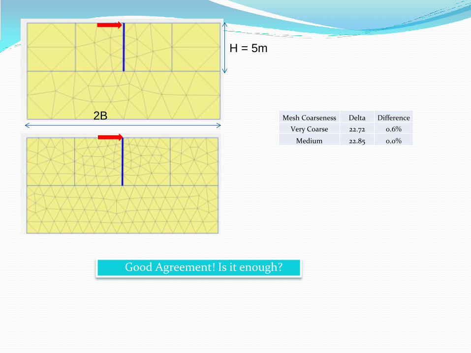
H = 5m
2B Mesh Coarseness Delta Difference
Very Coarse 22.72 0.6%
Medium 22.85 0.0%
Good Agreement! Is it enough?
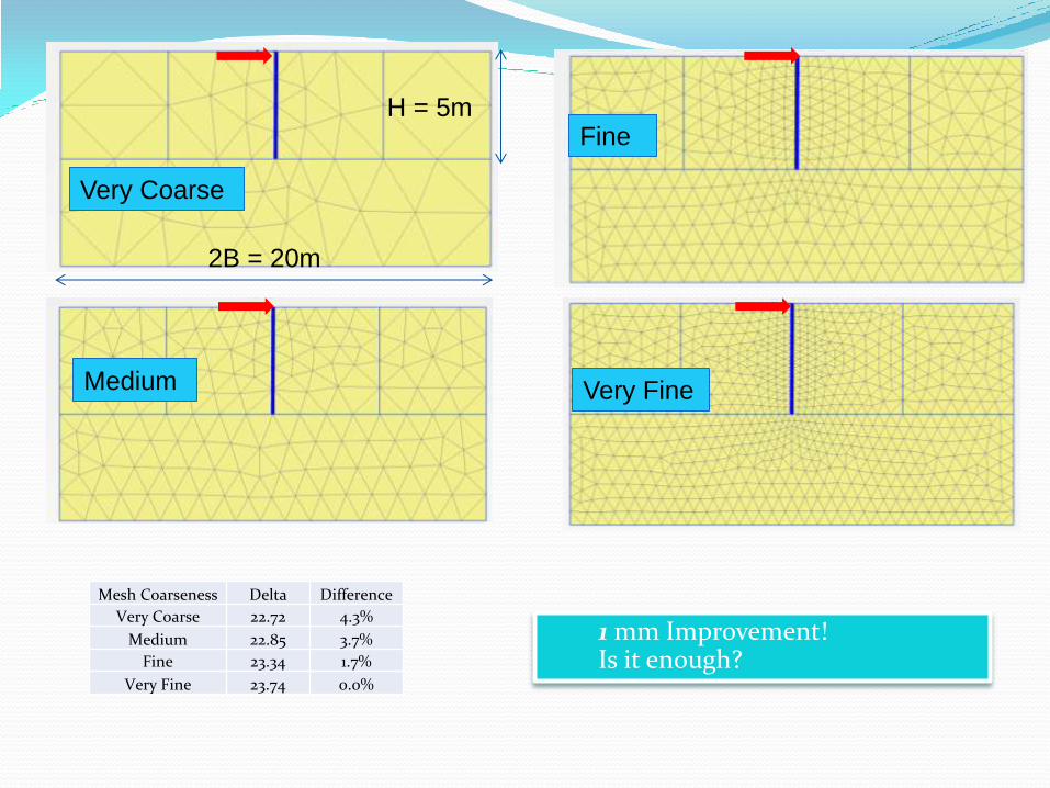
H = 5m
2B = 20m
1 mm Improvement! Is it enough?
Mesh Coarseness Delta Difference
Very Coarse 22.72 4.3%
Medium 22.85 3.7%
Fine 23.34 1.7%
Very Fine 23.74 0.0%
Very Coarse
Medium
Fine
Very Fine

H = 5m
B/H = 10
2B
B/H Delta Difference
1 19.03 27.0%
2 22.85 12.4%
3 24.74 5.1%
5 25.63 1.7%
10 26.07 0.0%
B/H = 5
B/H = 2
B/H = 3
B/H = 1
Convergence Doesn’t Mean Accurate!
1
10
5
To the FE Program Problems 1,5, and 10 are different BVP (boundary value problems) To the analysts/users, they may be used to simulate the same physical problems. The physical reality of the physical problems may NOT be Case 10.
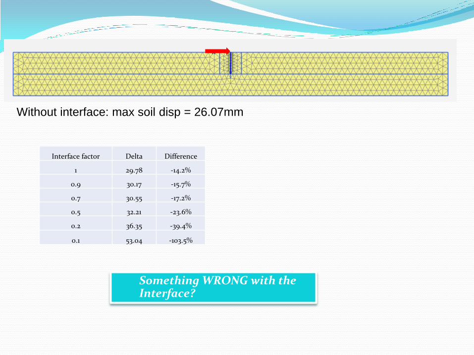
Interface factor Delta Difference
1 29.78 -14.2%
0.9 30.17 -15.7%
0.7 30.55 -17.2%
0.5 32.21 -23.6%
0.2 36.35 -39.4%
0.1 53.04 -103.5%
Without interface: max soil disp = 26.07mm
Something WRONG with the Interface?
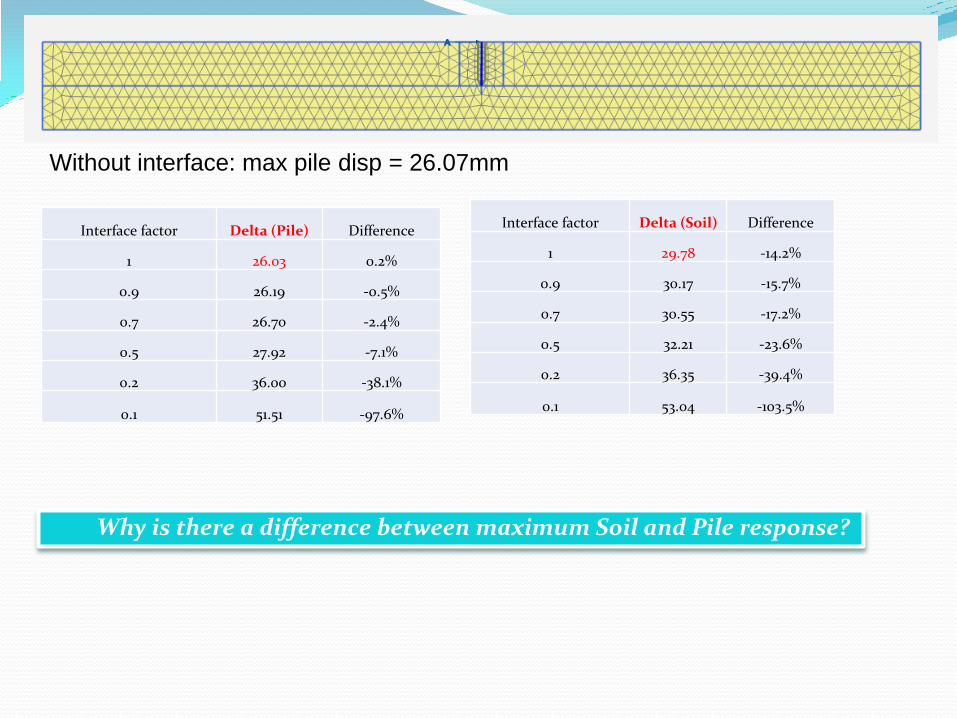
Without interface: max pile disp = 26.07mm
Interface factor Delta (Pile) Difference
1 26.03 0.2%
0.9 26.19 -0.5%
0.7 26.70 -2.4%
0.5 27.92 -7.1%
0.2 36.00 -38.1%
0.1 51.51 -97.6%
Why is there a difference between maximum Soil and Pile response?
Interface factor Delta (Soil) Difference
1 29.78 -14.2%
0.9 30.17 -15.7%
0.7 30.55 -17.2%
0.5 32.21 -23.6%
0.2 36.35 -39.4%
0.1 53.04 -103.5%

Interface displacement plot Wall displacement plot
The difference is related to the element itself !


Contact Elements
Attached to the Cylinder
Contact Elements
Attached to theTop Plate
Contact Elements Attached
to the Bottom Plate
Surface Separation lines
Top Plate
Cylinder
Bottom Plate
40”
24.2”
31.8” F=10”
Max Pressure =33.6 ksi
Min Pressure = 9.0 ksi

Knowledge
Knowledge on Numerical
Methods (FEM, continuum
mechanics)
Numerical Modeling and It’s State of Practice
Knowledge about
Subject (Soil Mechanics,
Material Science)
Real World
Problem
Simplified Problem
Performance, Monitoring Data, Etc.
Solution
Verification
Traditional Methods

Study the Software! Study the tutorial and examples provided in the manual
Run benchmark problems
Sanity check
Hand calculation to know the cause-effect relationship
Use common sense and engineering sense Don’t believe in the accuracy of the displacement contour if
your material model is not right or the parameters are off-limit

For Engineers in Charge Form a team with both analytical skills and engineering
experience
Give enough time to the analyst, start as early as possible
Try to involve experienced engineers early in the modeling phase, especially when deciding loading, boundary conditions, material models
Make sure the analyst has gone through the benchmark problems before tackling a real-world problem
Understand the limitation of the simulation results and its usage

Concluding Remarks: Be aware, be alert and be cautious
When to ask for help? Not sure what loading to apply
Discuss with experienced engineer to find out the correct magnitude
Make sure the way you apply loading doesn’t affect the results
adversely (line loading, point loading, pressure loadings etc)
Not sure of how many stages are needed
Be aware of what parameters are used Perform some kind of sensitivity study if time permitted
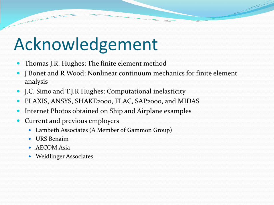
Acknowledgement Thomas J.R. Hughes: The finite element method
J Bonet and R Wood: Nonlinear continuum mechanics for finite element analysis
J.C. Simo and T.J.R Hughes: Computational inelasticity
PLAXIS, ANSYS, SHAKE2000, FLAC, SAP2000, and MIDAS
Internet Photos obtained on Ship and Airplane examples
Current and previous employers
Lambeth Associates (A Member of Gammon Group)
URS Benaim
AECOM Asia
Weidlinger Associates

Thank You! Questions? Comments?
___________________________________________
Lambeth Associates Limited
(A member of Gammon Group)
28/F Devon House, Taikoo Place, 979 King's Rd, Hong Kong
Tel: (852) 2516 8688 Fax: (852) 2516 6352


![SPA Serge Pun & Associates (SPA Group) First Myanmar ... · [Type here] Serge Pun & Associates Ltd. FMI Centre, 10th Floor 380 Bogyoke Aung San Road Pabedan Tsp, Yangon, Myanmar Tel:](https://img.pdfslide.tips/doc/110x75/5e0ad4793dd9203935290d23/spa-serge-pun-associates-spa-group-first-myanmar-type-here-serge-pun.jpg)