Embed Size (px)
Citation preview
1
Forschungszentrum Karlsruhein der Helmholtz-Gemeinschaft
Durability and Restoration of Concrete Structures
Prof. Dr. Andreas Gerdes
Forschungszentrum Karlsruhein der Helmholtz-Gemeinschaft
Properties of cement based materials
• Structure• Chemical reactivity
Forschungszentrum Karlsruhein der Helmholtz-Gemeinschaft
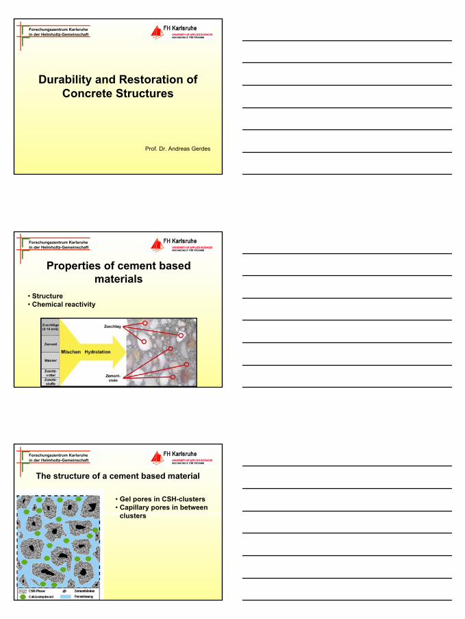
The structure of a cement based material
• Gel pores in CSH-clusters• Capillary pores in between
clusters
2
Forschungszentrum Karlsruhein der Helmholtz-Gemeinschaft
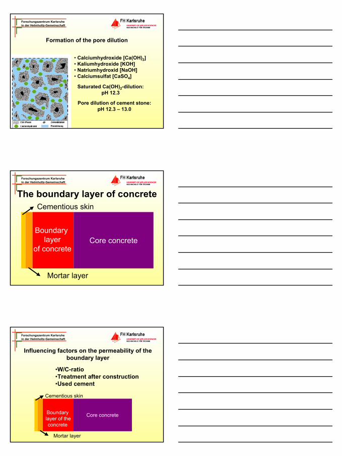
Formation of the pore dilution
• Calciumhydroxide [Ca(OH)2]• Kaliumhydroxide [KOH]• Natriumhydroxid [NaOH]• Calciumsulfat [CaSO4]
Saturated Ca(OH)2-dilution: pH 12.3
Pore dilution of cement stone:pH 12.3 – 13.0
Forschungszentrum Karlsruhein der Helmholtz-Gemeinschaft
The boundary layer of concrete
Core concreteBoundary
layerof concrete
Mortar layer
Cementious skin
Forschungszentrum Karlsruhein der Helmholtz-Gemeinschaft
Influencing factors on the permeability of the boundary layer
Core concreteBoundarylayer of theconcrete
Mortar layer
Cementious skin
•W/C-ratio•Treatment after construction•Used cement
3
Forschungszentrum Karlsruhein der Helmholtz-Gemeinschaft
Permeability of cement based materials
The analysis undertaken by POWER‘s are existing already are originated from the 1950`s.
Forschungszentrum Karlsruhein der Helmholtz-Gemeinschaft
Influence of the W/C-ratio on the pore structure• After hydration water is bounded in different forms in the
structure. > Chemically> Adsorbed in gel pores> In the capillary pores (area of transport processes)
Forschungszentrum Karlsruhein der Helmholtz-Gemeinschaft
Influence of treatment after construction on the structure of the pores
• Sufficient treatment increases the density of the boundary layer.•The treatment is enabled by using, transparent slides, mats for storing water, water spray, treatment agents and finally concrete remains in formwork.Increase the penetration resistance
4
Forschungszentrum Karlsruhein der Helmholtz-Gemeinschaft
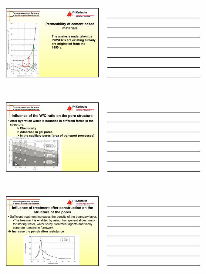
Impregnation of cement based materials
Forschungszentrum Karlsruhein der Helmholtz-Gemeinschaft
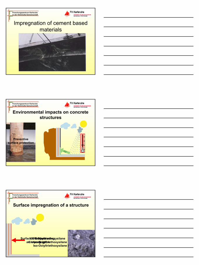
Environmental impacts on concretestructures
Cl --10
0
10
20
Preventivesurface protection
Forschungszentrum Karlsruhein der Helmholtz-Gemeinschaft
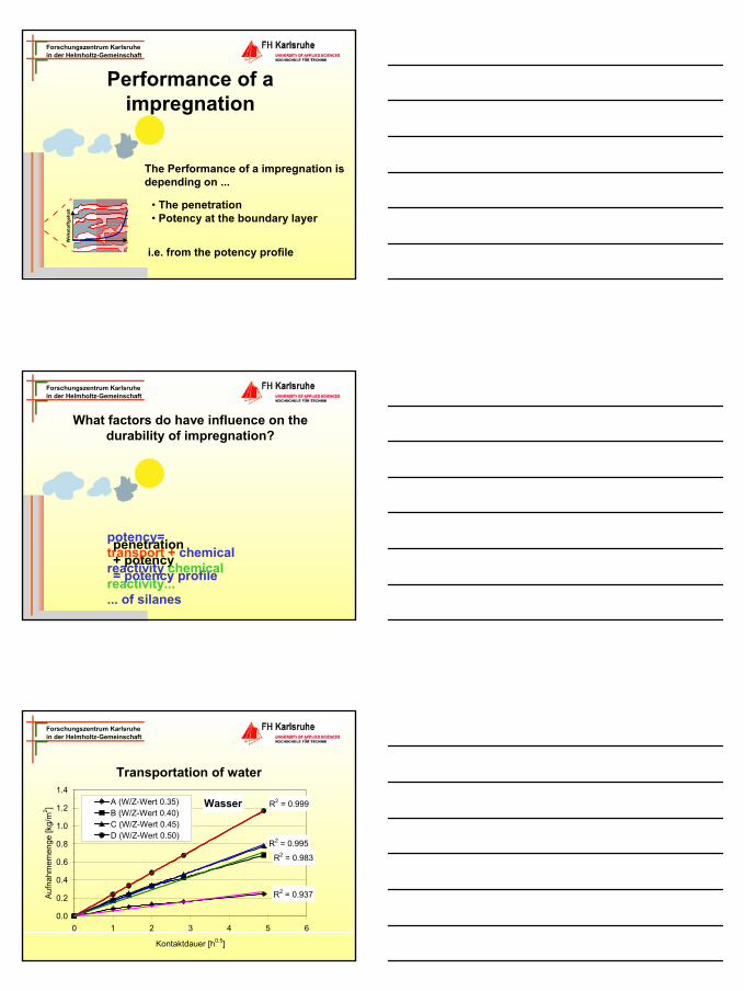
Surface impregnation of a structure
Surface treatment using an impregnation
100% SilaneCream or gel
PropyltriethoxysilaneIso-ButyltriethoxysilaneIso-Octyltriethoxysilane
5
Forschungszentrum Karlsruhein der Helmholtz-Gemeinschaft
Performance of a impregnation
The Performance of a impregnation is depending on ...
• The penetration• Potency at the boundary layer
i.e. from the potency profile
Wirk
stof
fgeh
alt
Forschungszentrum Karlsruhein der Helmholtz-Gemeinschaft
What factors do have influence on the durability of impregnation?
penetration+ potency= potency profile
potency=transport + chemical reactivity chemical reactivity...... of silanes
Forschungszentrum Karlsruhein der Helmholtz-Gemeinschaft
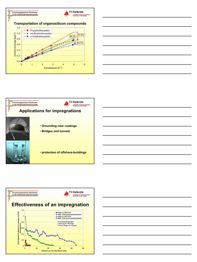
Wasser R2 = 0.999
R2 = 0.995
R2 = 0.983
R2 = 0.937
0.0
0.2
0.4
0.6
0.8
1.0
1.2
1.4
0 1 2 3 4 5 6
Kontaktdauer [h0.5]
Auf
nahm
emen
ge [k
g/m
2 ] A (W/Z-Wert 0.35)B (W/Z-Wert 0.40)C (W/Z-Wert 0.45)D (W/Z-Wert 0.50)
Transportation of water
6
Forschungszentrum Karlsruhein der Helmholtz-Gemeinschaft
Transportation of organosilicon compounds
0.0
0.2
0.4
0.6
0.8
1.0
1.2
0 1 2 3 4 5 6Kontaktdauer [h0.5]
Auf
nahm
emen
ge [k
g/m
2 ]
Propyltriethoxysilaniso-Butyltriethoxysilann-Octyltriethoxysilan 94.3%
80.7%
70.9%
Forschungszentrum Karlsruhein der Helmholtz-Gemeinschaft
Applications for impregnations
• Grounding near coatings
• Bridges and tunnels
• protection of offshore-buildings
Forschungszentrum Karlsruhein der Helmholtz-Gemeinschaft
Effectiveness of an impregnation
0
0.2
0.4
0.6
0.8
1
1.2
0 10 20 30 40 50Abstand von der Oberfläche [mm]
Chl
orid
geha
lt in
Mas
sen-
%, b
ezog
en a
uf d
as
Bet
onge
wic
ht
Silan A, W/Z 0.50W/Z 0.50 (nicht hydrophobiert)Silan A, W/Z 0.55W/Z 0.55 (nicht hydrophobiert)
Versuchsbedingungen:Lagerung für 180 Tage in einer 3%igen Cl--Lösung
7
Forschungszentrum Karlsruhein der Helmholtz-Gemeinschaft
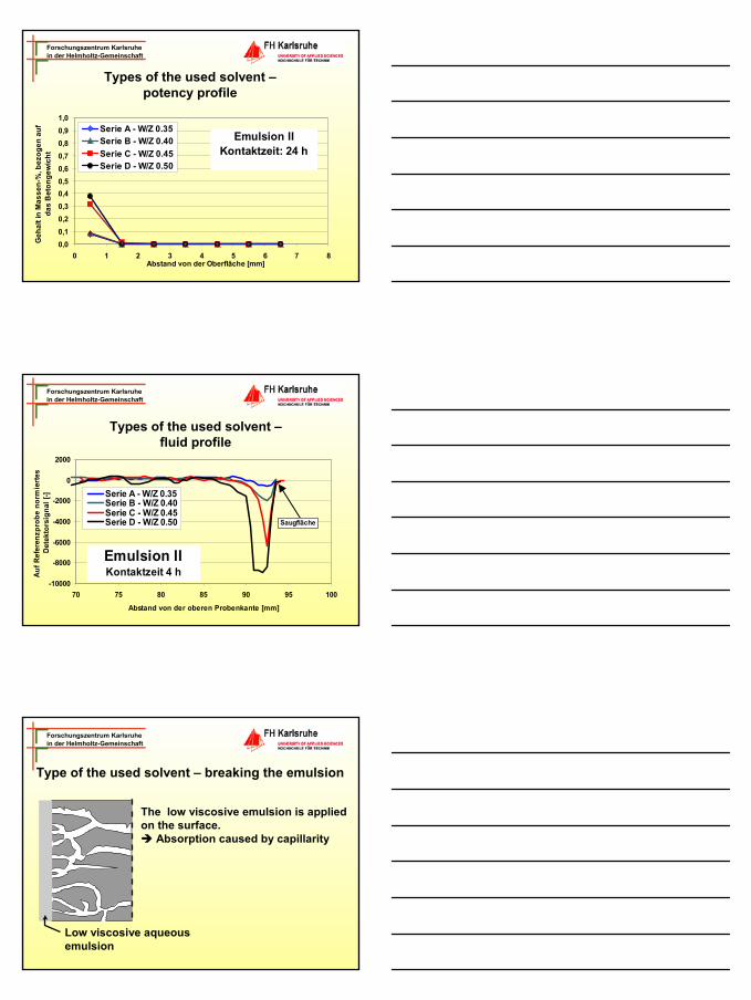
Types of the used solvent –potency profile
0,00,10,20,30,40,50,60,70,80,91,0
0 1 2 3 4 5 6 7 8Abstand von der Oberfläche [mm]
Geh
alt i
n M
asse
n-%
, bez
ogen
auf
da
s B
eton
gew
icht
Serie A - W/Z 0.35Serie B - W/Z 0.40Serie C - W/Z 0.45Serie D - W/Z 0.50
Emulsion IIKontaktzeit: 24 h
Forschungszentrum Karlsruhein der Helmholtz-Gemeinschaft
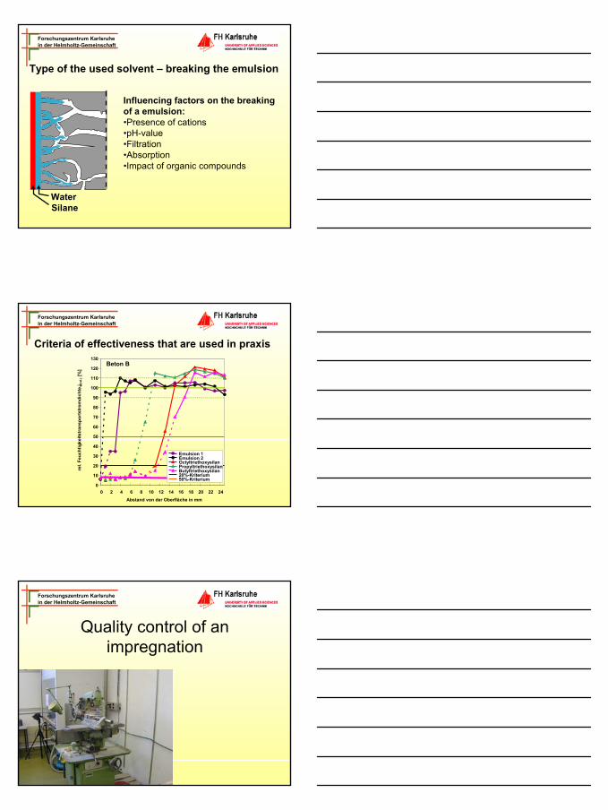
-10000
-8000
-6000
-4000
-2000
0
2000
70 75 80 85 90 95 100
Abstand von der oberen Probenkante [mm]
Auf R
efer
enzp
robe
nor
mie
rtes
Dete
ktor
sign
al [-
] Serie A - W/Z 0.35Serie B - W/Z 0.40Serie C - W/Z 0.45Serie D - W/Z 0.50 Saugfläche
Emulsion IIKontaktzeit 4 h
Types of the used solvent –fluid profile
Forschungszentrum Karlsruhein der Helmholtz-Gemeinschaft
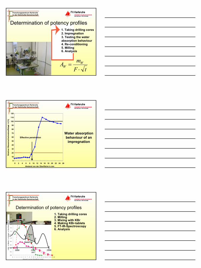
Type of the used solvent – breaking the emulsion
Low viscosive aqueousemulsion
The low viscosive emulsion is applied on the surface.
Absorption caused by capillarity
8
Forschungszentrum Karlsruhein der Helmholtz-Gemeinschaft
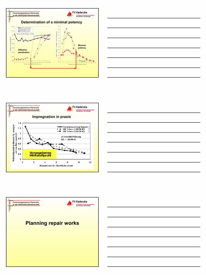
WaterSilane
Influencing factors on the breaking of a emulsion:•Presence of cations•pH-value•Filtration•Absorption•Impact of organic compounds
Type of the used solvent – breaking the emulsion
Forschungszentrum Karlsruhein der Helmholtz-Gemeinschaft
Criteria of effectiveness that are used in praxis
0
10
20
30
40
50
60
70
80
90
100
110
120
130
0 2 4 6 8 10 12 14 16 18 20 22 24Abstand von der Oberfläche in mm
rel.
Feuc
htig
keits
tran
spor
tstr
omdi
chte
j w(re
l.)[%
]
Emulsion 1Emulsion 2OctyltriethoxysilanPropyltriethoxysilan Butyltriethoxysilan20%-Kriterium50%-Kriterium
Beton B
Forschungszentrum Karlsruhein der Helmholtz-Gemeinschaft
Quality control of an impregnation
9
Forschungszentrum Karlsruhein der Helmholtz-Gemeinschaft
Determination of potency profiles1. Taking drilling cores2. Impregnation3. Testing the water absorption behaviour4. Re-conditioning5. Milling
tFmA W
W ⋅=
6. Analysis
Forschungszentrum Karlsruhein der Helmholtz-Gemeinschaft
Water absorption behaviour of an
impregnation
0
10
20
30
40
50
60
70
80
90
100
110
120
0 2 4 6 8 10 12 14 16 18 20 22 24 26Abstand von der Oberfläche in mm
Rel
ativ
er W
asse
rauf
nahm
ekoe
ffizi
ent
A[%
]re
l
Effective penetration
Forschungszentrum Karlsruhein der Helmholtz-Gemeinschaft
Determination of potency profiles1. Taking drilling cores2. Milling3. Mixing with KBr4. Making KBr-tablets5. FT-IR-Spectroscopy6. Analysis
0.0
0.2
0.4
0.6
0.8
1.0
1.2
1.4
1.6
1.8
2.0
2.2
2.4
0 1 2 3 4 5 6 7 8 9 10 11 12 13 14 15 16 17 18 19 20
Ab st an d von de r Obe rflä ch e in m m
10
Forschungszentrum Karlsruhein der Helmholtz-Gemeinschaft
Determination of a minimal potency
00.00
0.02
0.04
0.06
0.08
0.10
0.12
0.14
0.16
0 1 2 3 4 5 6 7 8 9 10 11 12 13 14 15 16 17 18 19 2
Referenz, unbehandeltPropy lt riet hoxy s ilanButyltrie thoxys ila nOctyltrie thoxys ila n
Beton B (W/Z-Wert 0.40)
Abst an d vo n de r Ob erflä ch e in m m
0.0
0.2
0.4
0.6
0.8
1.0
1.2
1.4
1.6
1.8
2.0
2.2
2.4
0 1 2 3 4 5 6 7 8 9 10 11 12 13 14 15 16 17 18 19 20Ab st an d von de r Obe rflä ch e in mm
Effective penetration
Minimalpotency
Forschungszentrum Karlsruhein der Helmholtz-Gemeinschaft
Impregnation in praxis1. Voruntersuchungen
2. Durchführung
3. Qualitätskontrolle
-Anlegen von Probeflächen-Entnahme von Bohrkernen-Bestimmung des Wirkstoff- und Saugprofils-Definition der Wirksamen Eindringtiefe und des Minimalen Wirkstoffgehaltes
-Hochviskose Hydrophobierungsmittel-Niedrigviskose Hydrophobierungsmittel
-Entnahme von Bohrkernen-Überprüfung der vertraglich fixierten Grössen
VorgegebenesWirkstoffprofil
Forschungszentrum Karlsruhein der Helmholtz-Gemeinschaft
Planning repair works
11
Forschungszentrum Karlsruhein der Helmholtz-Gemeinschaft
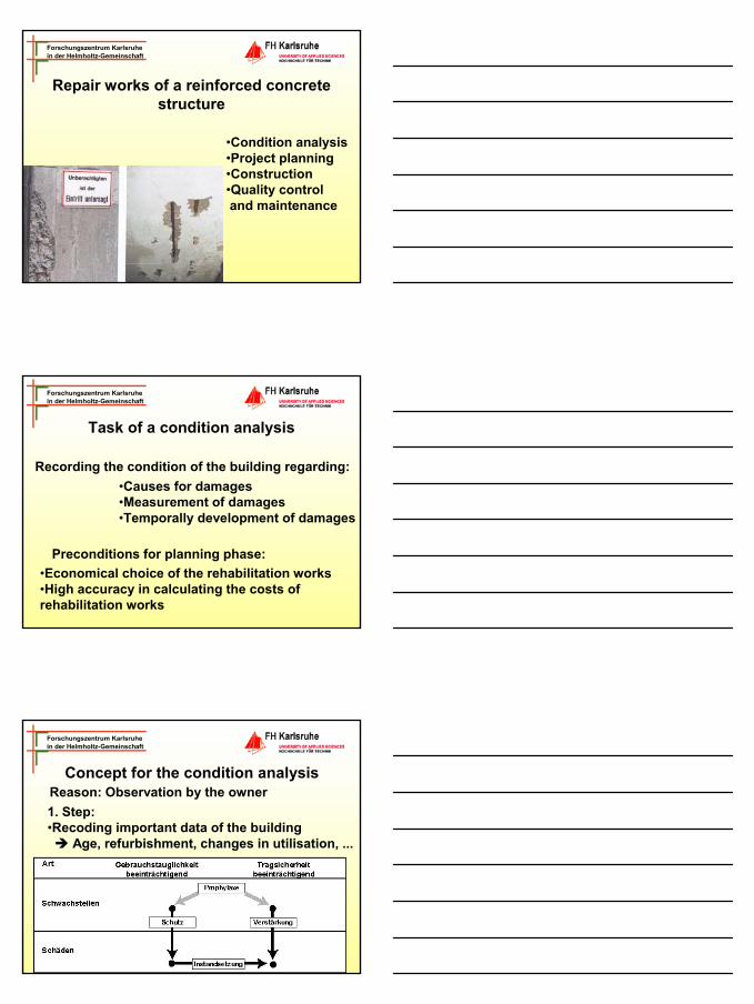
Repair works of a reinforced concrete structure
•Condition analysis•Project planning•Construction •Quality control and maintenance
Forschungszentrum Karlsruhein der Helmholtz-Gemeinschaft
Task of a condition analysis
•Causes for damages•Measurement of damages•Temporally development of damages
Preconditions for planning phase:
Recording the condition of the building regarding:
•Economical choice of the rehabilitation works•High accuracy in calculating the costs of rehabilitation works
Forschungszentrum Karlsruhein der Helmholtz-Gemeinschaft
Concept for the condition analysis
1. Step:•Recoding important data of the building
Age, refurbishment, changes in utilisation, ...
Reason: Observation by the owner
12
Forschungszentrum Karlsruhein der Helmholtz-Gemeinschaft
•Used materials (z.B. type of concrete)•Location of the building•Type and scale of utilisation•Scope (area)•Accessibility (e.g. scaffolding)•Danger (health and safety)•Construction (weak points)•Aspects regarding energy recovery (e.g. isolation)•Aesthetic aspects (shape, colour)
Concept for the condition analysis
Forschungszentrum Karlsruhein der Helmholtz-Gemeinschaft
Scope of the condition analysis
•Phase I: Visual appraisal (photos/drawings)
•Phase II: Analysis of the building on site
•Phase III: Laboratory Analysis
Forschungszentrum Karlsruhein der Helmholtz-Gemeinschaft
Phase I: Visual appraisal
•Cracks and pictures of cracking•Leaking splices•Spalling•Inhomogeneous concrete•Applied repair work•Paintworks •blowhole•Natural cover•Water (e.g. water from penetration)•Pollution and scum's
Documentation
13
Forschungszentrum Karlsruhein der Helmholtz-Gemeinschaft
Phase I: Visual appraisalFrom this the following can be derived:
-Stability problems -Risk for brittle fracture -Inroad of the building-Deformation-Cracking -Falling Items
Forschungszentrum Karlsruhein der Helmholtz-Gemeinschaft
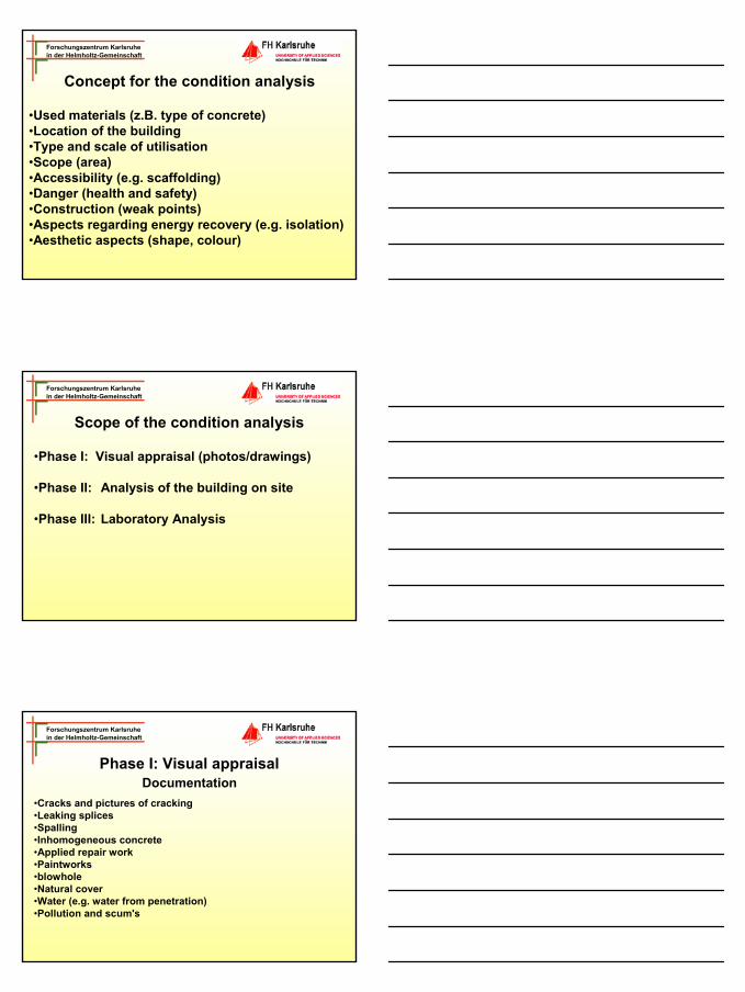
Phase II: Measurement on site
Grid-cut-testing
Adhesive tensile strength
Natural coverCracking lineSpallingBlowhole
Measurement withmeasuring stick
Inhomogeneousconcrete
Geologists hammer
paintworkAdhesive tensile toolsGrid-cut-testing
Forschungszentrum Karlsruhein der Helmholtz-Gemeinschaft
Phase II: Measurement of concreteCompression strength Schmidt-hammerAdhesive tensile strength Adhesive tensile testing toolsCarbonation depth Taking drilling coresMoisture content Moisture measurement toolsWater absorption Karsten-tubeChloride penetration „Silver nitrate/Chromate-test“
14
Forschungszentrum Karlsruhein der Helmholtz-Gemeinschaft
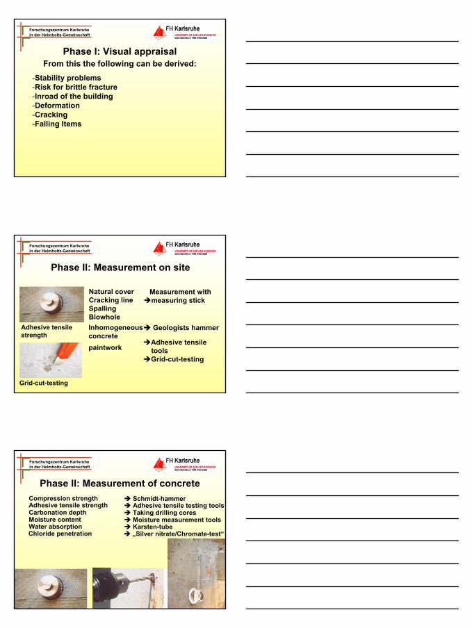
Phase II: Measurement of reinforcementPosition of the reinforcement Tool for searching the
reinforcement Condition of the corrosion Measuring the field of potential
The corrosion condition comprises:Position and scope of the corrosion areaSupplemented by:
Chloride distributionCarbonationMoisture distribution
Forschungszentrum Karlsruhein der Helmholtz-Gemeinschaft
Phase II: Principle of measuring the potential
Corroding and passive steel are the macro elementsCaused by the elec. current an electrical field is originatedAn electrode is used for referencing
Measurement of the potential field and position
Forschungszentrum Karlsruhein der Helmholtz-Gemeinschaft
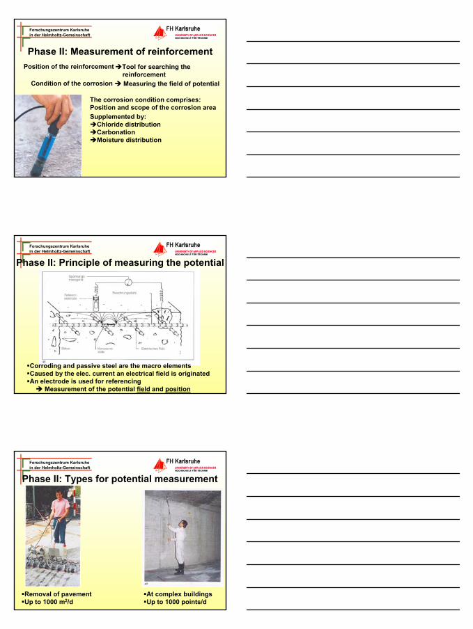
Phase II: Types for potential measurement
Removal of pavementUp to 1000 m2/d
At complex buildingsUp to 1000 points/d
15
Forschungszentrum Karlsruhein der Helmholtz-Gemeinschaft
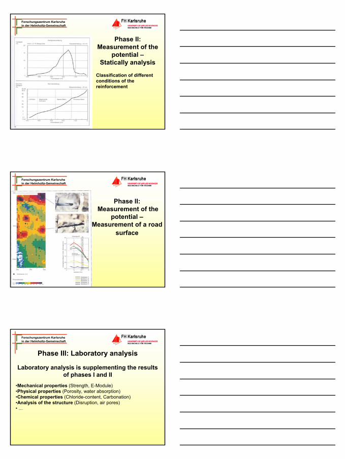
Phase II: Measurement of the
potential –Statically analysis
Classification of different conditions of the reinforcement
Forschungszentrum Karlsruhein der Helmholtz-Gemeinschaft
Phase II: Measurement of the
potential –Measurement of a road
surface
Forschungszentrum Karlsruhein der Helmholtz-Gemeinschaft
Phase III: Laboratory analysis
•Mechanical properties (Strength, E-Module)•Physical properties (Porosity, water absorption)•Chemical properties (Chloride-content, Carbonation)•Analysis of the structure (Disruption, air pores)• ...
Laboratory analysis is supplementing the results of phases I and II

16
Forschungszentrum Karlsruhein der Helmholtz-Gemeinschaft
Appraisal of the condition data
•Scope and reason of the damages•Weak points•Development of damages (regarding time)•Safety of the building•Example carbonation
Appraisal of the gathered data regarding:
Forschungszentrum Karlsruhein der Helmholtz-Gemeinschaft
Repair works of a concrete facade Carbonation
Forschungszentrum Karlsruhein der Helmholtz-Gemeinschaft
Project planning of repair works carbonation
The task of project planning is to develop different steps to carry out work and to eliminate weak points.
Avoid damages in futureDecision on the maintenance that is needed
17
Forschungszentrum Karlsruhein der Helmholtz-Gemeinschaft
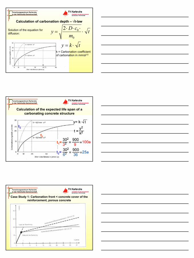
Calculation of carbonation depth – √t-law
Solution of the equation for diffusion: t
mcDy ⋅
⋅⋅⋅=
0
02
k = Carbonation coefficient of carbonation in mm/a0.5
tky ⋅=
Forschungszentrum Karlsruhein der Helmholtz-Gemeinschaft
Calculation of the expected life span of a carbonating concrete structure
t1
t2
t1=
t2=
Forschungszentrum Karlsruhein der Helmholtz-Gemeinschaft
Case Study 1: Carbonation front < concrete cover of the reinforcement, porous concrete
18
Forschungszentrum Karlsruhein der Helmholtz-Gemeinschaft
Carbonation - Planning of restoration measures
• Coating of the concrete surface with a polymer coating with a high resistance against CO2-diffusion
Forschungszentrum Karlsruhein der Helmholtz-Gemeinschaft
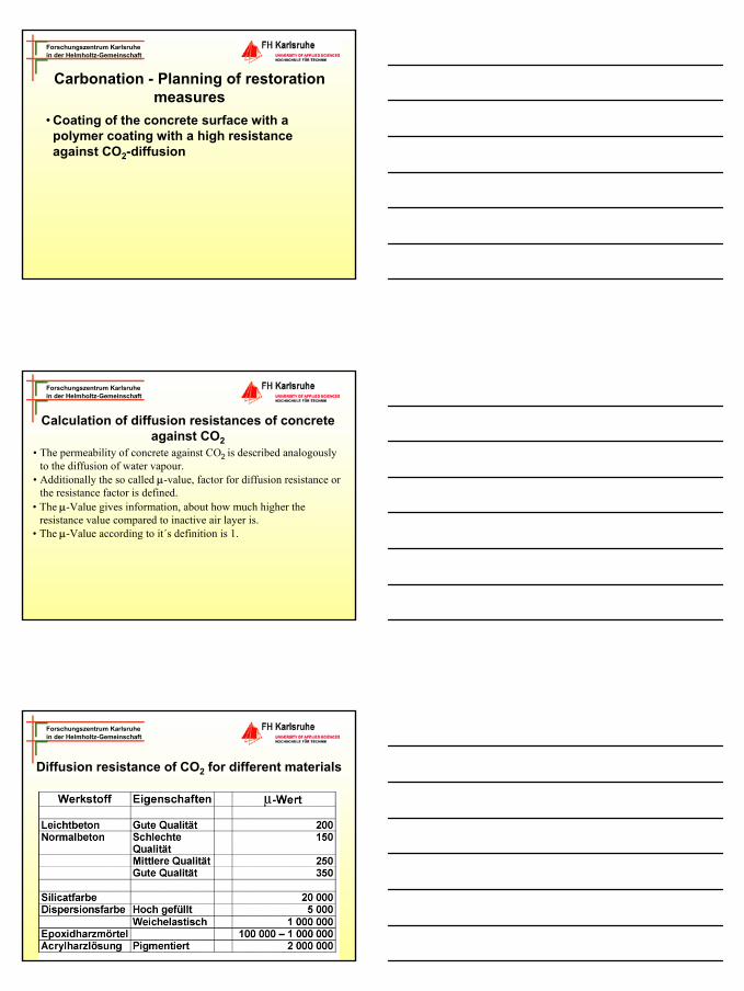
Calculation of diffusion resistances of concrete against CO2
• The permeability of concrete against CO2 is described analogously to the diffusion of water vapour.
• Additionally the so called µ-value, factor for diffusion resistance or the resistance factor is defined.
• The µ-Value gives information, about how much higher the resistance value compared to inactive air layer is.
• The µ-Value according to it´s definition is 1.
Forschungszentrum Karlsruhein der Helmholtz-Gemeinschaft
Diffusion resistance of CO2 for different materials
19
Forschungszentrum Karlsruhein der Helmholtz-Gemeinschaft
Calculation of the diffusion-equivalent air film thickness R
µCO2 . s = R
s = film thickness [m]R = diffusion-equivalent thickness of the air film
Example:µ-value for concrete, good quality: 300Thickness of concrete s : 15 mm
300 . 0.015 m = 4.5 m
Forschungszentrum Karlsruhein der Helmholtz-Gemeinschaft
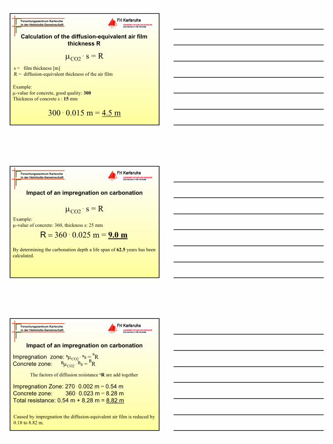
Impact of an impregnation on carbonation
µCO2 . s = R
Example:µ-value of concrete: 360, thickness s: 25 mm
R = 360 . 0.025 m = 9.0 m
By determining the carbonation depth a life span of 62.5 years has been calculated.
Forschungszentrum Karlsruhein der Helmholtz-Gemeinschaft
Impregnation zone: sµCO2 . ss = sR
Concrete zone: BµCO2 . Bs = BR
Caused by impregnation the diffusion-equivalent air film is reduced by 0.18 to 8.82 m.
The factors of diffusion resistance xR are add together
Impregnation Zone: 270 . 0.002 m = 0.54 mConcrete zone: 360 . 0.023 m = 8.28 m Total resistance: 0.54 m + 8.28 m = 8.82 m
Impact of an impregnation on carbonation
20
Forschungszentrum Karlsruhein der Helmholtz-Gemeinschaft
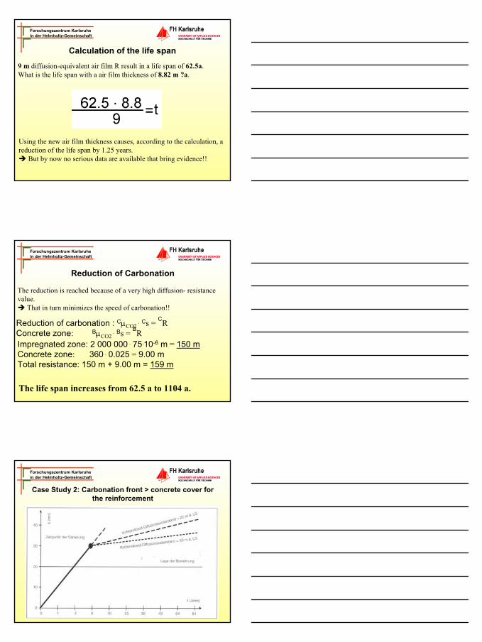
Calculation of the life span
9 m diffusion-equivalent air film R result in a life span of 62.5a.What is the life span with a air film thickness of 8.82 m ?a.
Using the new air film thickness causes, according to the calculation, a reduction of the life span by 1.25 years.
But by now no serious data are available that bring evidence!!
Forschungszentrum Karlsruhein der Helmholtz-Gemeinschaft
Reduction of Carbonation
The reduction is reached because of a very high diffusion- resistance value.
That in turn minimizes the speed of carbonation!!
Reduction of carbonation : CµCO2 . Cs = CR
Concrete zone: BµCO2 . Bs = BR
Impregnated zone: 2 000 000 . 75.10-6 m = 150 mConcrete zone: 360 . 0.025 = 9.00 mTotal resistance: 150 m + 9.00 m = 159 m
The life span increases from 62.5 a to 1104 a.
Forschungszentrum Karlsruhein der Helmholtz-Gemeinschaft
Case Study 2: Carbonation front > concrete cover for the reinforcement

21
Forschungszentrum Karlsruhein der Helmholtz-Gemeinschaft
Project planning of repair works carbonation
•Removing the cover concrete•Uncovering the reinforcement•Covering the reinforcement •Repair works using shotcrete
Forschungszentrum Karlsruhein der Helmholtz-Gemeinschaft
Dismantling of concrete
Forschungszentrum Karlsruhein der Helmholtz-Gemeinschaft
Basics of high water pressure spraying (HWS)
Principle:A water-jet with a very high speed is produced by pushing water through a valve.(Pressure: many 100 up to 1000 bar)
High kinetically energy
22
Forschungszentrum Karlsruhein der Helmholtz-Gemeinschaft
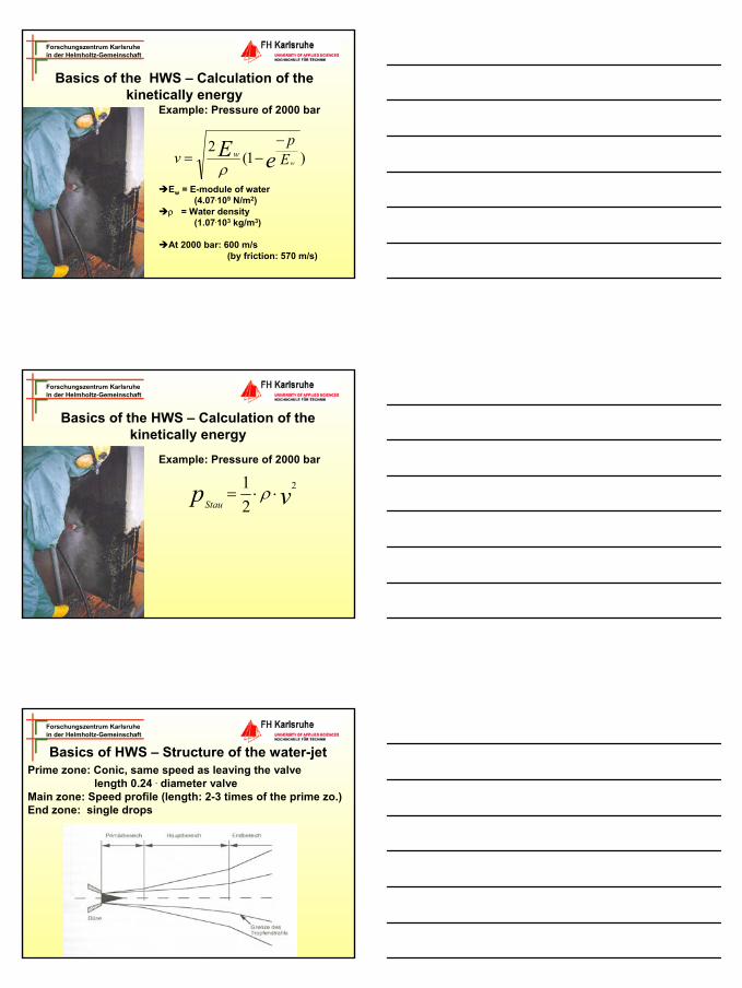
Basics of the HWS – Calculation of the kinetically energy
Example: Pressure of 2000 bar
Ew = E-module of water (4.07.109 N/m2)
ρ = Water density (1.07.103 kg/m3)
At 2000 bar: 600 m/s (by friction: 570 m/s)
)1(2
eE Ep
v ww
−−=
ρ
Forschungszentrum Karlsruhein der Helmholtz-Gemeinschaft
Example: Pressure of 2000 bar
vpStau2
21
⋅⋅= ρ
Basics of the HWS – Calculation of the kinetically energy
Forschungszentrum Karlsruhein der Helmholtz-Gemeinschaft
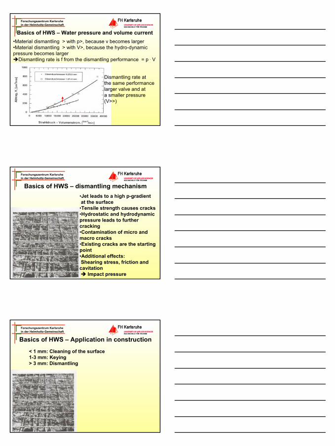
Basics of HWS – Structure of the water-jetPrime zone: Conic, same speed as leaving the valve
length 0.24 . diameter valveMain zone: Speed profile (length: 2-3 times of the prime zo.)End zone: single drops
23
Forschungszentrum Karlsruhein der Helmholtz-Gemeinschaft
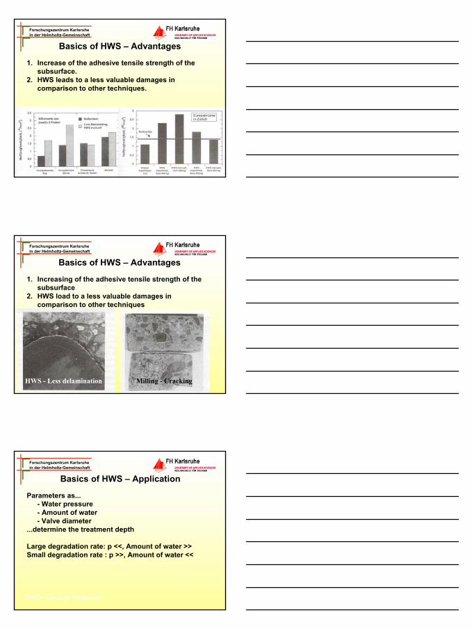
Basics of HWS – Water pressure and volume current•Material dismantling > with p>, because v becomes larger•Material dismantling > with V>, because the hydro-dynamic pressure becomes larger
Dismantling rate is f from the dismantling performance = p . V
Dismantling rate at the same performancelarger valve and at a smaller pressure (V>>)
Forschungszentrum Karlsruhein der Helmholtz-Gemeinschaft
Basics of HWS – dismantling mechanism•Jet leads to a high p-gradient at the surface•Tensile strength causes cracks•Hydrostatic and hydrodynamic pressure leads to further cracking•Contamination of micro and macro cracks•Existing cracks are the starting point•Additional effects:Shearing stress, friction and cavitation
Impact pressure
Forschungszentrum Karlsruhein der Helmholtz-Gemeinschaft
Basics of HWS – Application in construction
< 1 mm: Cleaning of the surface 1-3 mm: Keying> 3 mm: Dismantling
24
Forschungszentrum Karlsruhein der Helmholtz-Gemeinschaft
Basics of HWS – Advantages
1. Increase of the adhesive tensile strength of the subsurface.
2. HWS leads to a less valuable damages in comparison to other techniques.
Forschungszentrum Karlsruhein der Helmholtz-Gemeinschaft
Basics of HWS – Advantages
1. Increasing of the adhesive tensile strength of the subsurface
2. HWS load to a less valuable damages in comparison to other techniques
HWS - Less delamination Milling - Cracking
Forschungszentrum Karlsruhein der Helmholtz-Gemeinschaft
Basics of HWS – Application
Parameters as...- Water pressure- Amount of water- Valve diameter
...determine the treatment depth
Large degradation rate: p <<, Amount of water >>Small degradation rate : p >>, Amount of water <<
HWS- Geringe Ablösung
25
Forschungszentrum Karlsruhein der Helmholtz-Gemeinschaft
Cement based coatings
Forschungszentrum Karlsruhein der Helmholtz-Gemeinschaft
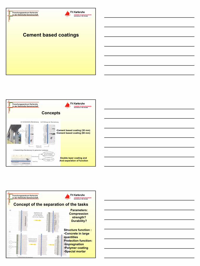
Concepts
•Cement based coating (30 mm)•Cement based coating (80 mm)
Double layer coating and And separation of function
Forschungszentrum Karlsruhein der Helmholtz-Gemeinschaft
Concept of the separation of the tasksParameters:
Compression strength?
Durability?
Structure function :•Concrete in large quantitiesProtection function:•Impregnation•Polymer coating•Special mortar
26
Forschungszentrum Karlsruhein der Helmholtz-Gemeinschaft
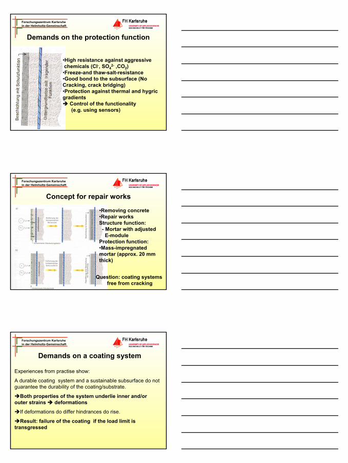
Demands on the protection function
•High resistance against aggressive chemicals (Cl-, SO4
2- ,CO2)•Freeze-and thaw-salt-resistance•Good bond to the subsurface (No Cracking, crack bridging)•Protection against thermal and hygricgradients
Control of the functionality(e.g. using sensors)
Forschungszentrum Karlsruhein der Helmholtz-Gemeinschaft
Concept for repair works
•Removing concrete•Repair worksStructure function:- Mortar with adjustedE-module
Protection function:•Mass-impregnated mortar (approx. 20 mm thick)
Question: coating systems free from cracking
Forschungszentrum Karlsruhein der Helmholtz-Gemeinschaft
Demands on a coating system
Experiences from practise show:
A durable coating system and a sustainable subsurface do not guarantee the durability of the coating/substrate.
Both properties of the system underlie inner and/or outer strains deformations
If deformations do differ hindrances do rise.
Result: failure of the coating if the load limit is transgressed
27
Forschungszentrum Karlsruhein der Helmholtz-Gemeinschaft
Demands of a coating system - Appraisal
The ability of a material of a system to take hindrances and loads is determined by:•Elastic deformation E•Fracture energy Gf•Ability to creep J
Meaning of different impacts:Physical impacts largeMechanical impacts smallChemical impacts avoidable
Forschungszentrum Karlsruhein der Helmholtz-Gemeinschaft
Tension- and deformation analysisAccording to a numerical model, that describes
•Endogenous Shrinkage
•Shrinkage caused by drying
•Creep
•Appearance of cracking
... using non-linear fracture mechanics, the relevant material parameters are described that are crucial for cracking of a coating
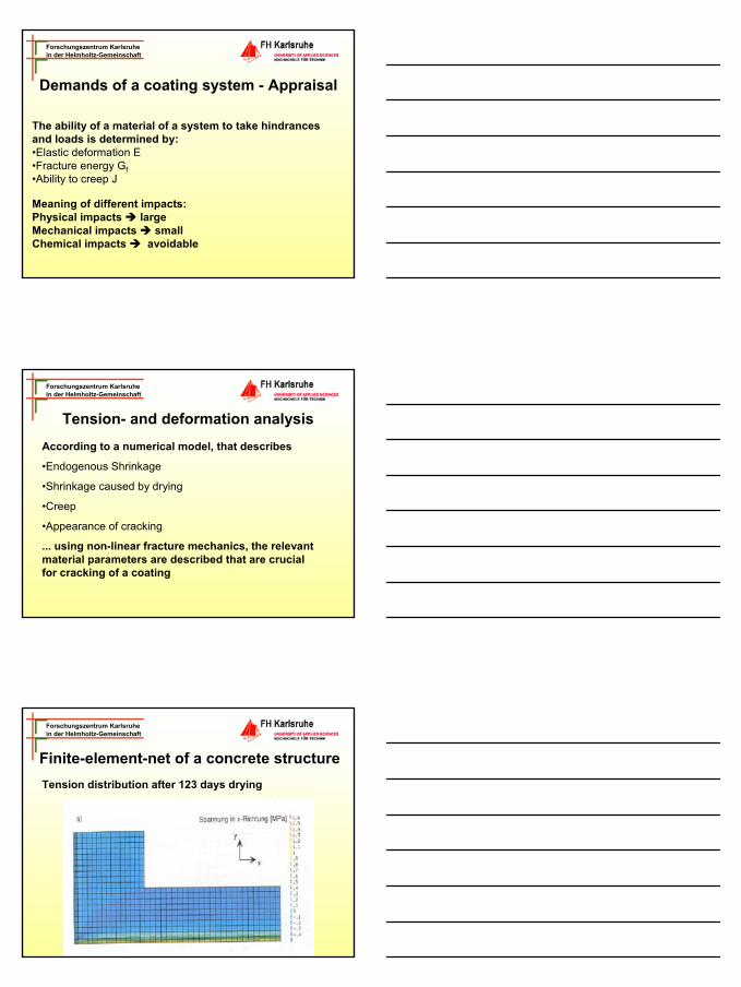
Forschungszentrum Karlsruhein der Helmholtz-Gemeinschaft
Finite-element-net of a concrete structureTension distribution after 123 days drying
28
Forschungszentrum Karlsruhein der Helmholtz-Gemeinschaft
Risk reduction of cracking and delamination
Using the numeric model, the following material parameters have been identified:
•Hygric alternatively thermal Extension coefficient
•Fracture energy
•E-Module
•Appearance of cracking
Forschungszentrum Karlsruhein der Helmholtz-Gemeinschaft
Risk for cracking as function of the fracture energy, the E-module, final material shrinkage and the hygric extension-
coefficient
Forschungszentrum Karlsruhein der Helmholtz-Gemeinschaft
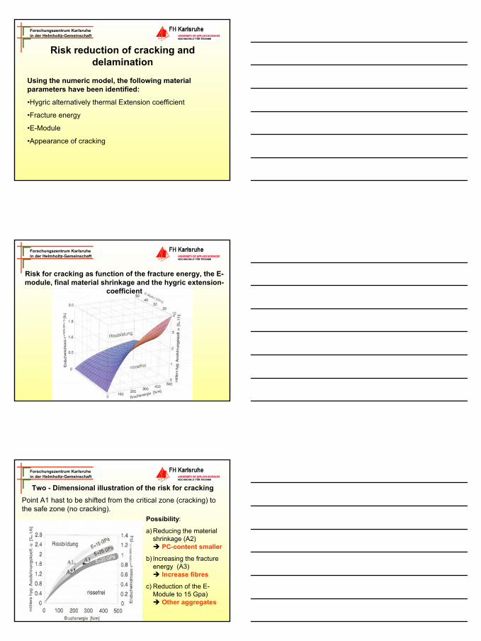
Two - Dimensional illustration of the risk for crackingPoint A1 hast to be shifted from the critical zone (cracking) tothe safe zone (no cracking).
Possibility:
a) Reducing the material shrinkage (A2)
PC-content smaller
b) Increasing the fracture energy (A3)
Increase fibres
c) Reduction of the E-Module to 15 Gpa)
Other aggregates

29
Forschungszentrum Karlsruhein der Helmholtz-Gemeinschaft
Delamination of coatings
For the dissolution of the coatings (delaminate) the following parameters play a major role:•Strength in between the boundary layer •Fracture energy near to the boundary zone
It is essential:
At a high fractural energy and hygric strain, but a weak strength in between the boundary layer, it is more likely that the coating dissolutes than the coating strains.
Forschungszentrum Karlsruhein der Helmholtz-Gemeinschaft
Delamination of coatings
High mechanical strength and fracture energy of the subsurface can be reached by:•Sufficient roughness of the subsurface•Application of primer (polymers)
Forschungszentrum Karlsruhein der Helmholtz-Gemeinschaft
Case study: Repair works of a 25 year old concrete bridge
Alternatives for repair works:a) Fibre-reinforced mortar with a max.
aggregate size of 3 mm and a W/C-ratio of 0.38. Thickness of the layer that amounts 60 mm.
b) Concrete with a max. aggregate size of 8 mm and a W/C-Ratio of 0.36. The thickness of the layer that amounts 70 mm.
c) Shortcrete with a max. aggregate size of 8 mm and W/C-ratio of 0.38. The thickness that amounts 55 mm.Finally impregnated mortar with a layer thickness of von 5-10 mm.
30
Forschungszentrum Karlsruhein der Helmholtz-Gemeinschaft
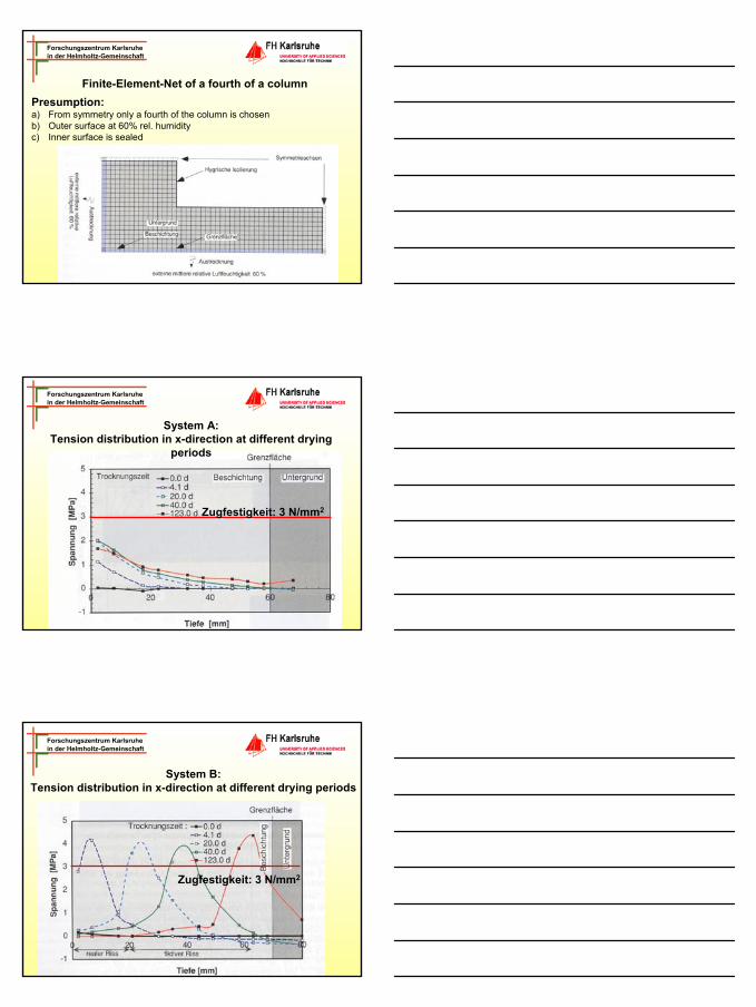
Finite-Element-Net of a fourth of a columnPresumption:a) From symmetry only a fourth of the column is chosenb) Outer surface at 60% rel. humidityc) Inner surface is sealed
Forschungszentrum Karlsruhein der Helmholtz-Gemeinschaft
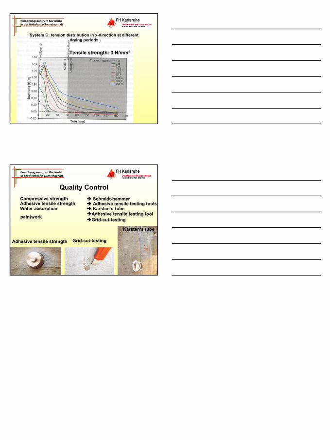
Zugfestigkeit: 3 N/mm2
System A: Tension distribution in x-direction at different drying
periods
Forschungszentrum Karlsruhein der Helmholtz-Gemeinschaft
System B: Tension distribution in x-direction at different drying periods
Zugfestigkeit: 3 N/mm2
31
Forschungszentrum Karlsruhein der Helmholtz-Gemeinschaft
Tensile strength: 3 N/mm2
System C: tension distribution in x-direction at different drying periods
Forschungszentrum Karlsruhein der Helmholtz-Gemeinschaft
Quality ControlCompressive strength Schmidt-hammer
Adhesive tensile testing toolsWater absorption Karsten‘s-tube
paintwork Adhesive tensile testing toolGrid-cut-testing
Grid-cut-testingAdhesive tensile strength
Karsten‘s tube
Adhesive tensile strength