Embed Size (px)
Citation preview

5/7/2010
1
EE215 – FUNDAMENTALS OF ELECTRICAL ENGINEERING
Tai-Chang Chen
University of Washington, Bothell
Spring 2010
EE215 1
WEEK 6OPERATIONAL AMPLIFIERS II & C; L ;
MUTUAL INDUCTANCE
May 14th , 2010
EE215 2© TC Chen UWB 2010
5/7/2010
2
QUESTIONS TO ANSWER• Operational Amplifier
– What are the common configurations of op amps and their gains?
• Inductors
– What is an inductor and its circuit symbol?
– How to calculate the current and voltage of an inductor?
– How to simplify inductors connected in parallel or series?
• Capacitors
– What is a capacitor and its circuit symbol?
– How to calculate the current and voltage of a capacitor?
– How to simplify capacitors connected in parallel or series?
EE215 3© TC Chen UWB 2010
OPERATIONAL AMPLIFIER II
May 14th , 2010
EE215 4© TC Chen UWB 2010
5/7/2010
3
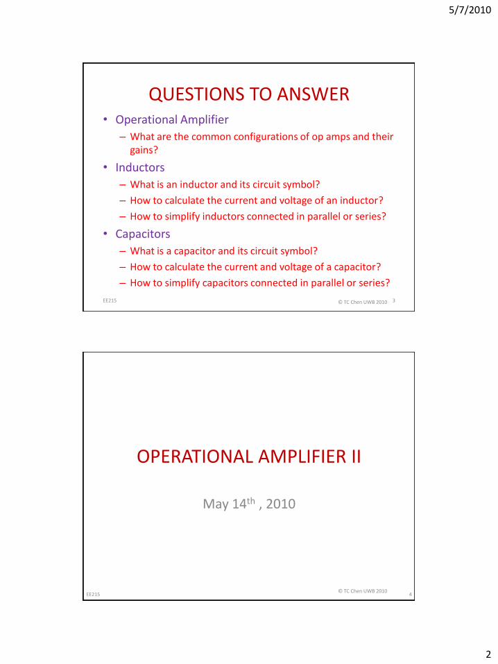
OPERATIONAL AMPLIFIER (10)
• Non-inverting Amplifier:
EE215 5© TC Chen UWB 2010
OPERATIONAL AMPLIFIER (11)
• Differential Amplifier:
EE215 6© TC Chen UWB 2010
5/7/2010
4
OPERATIONAL AMPLIFIER (12)
Remember:
• Input current: ip = in = 0
• Virtual short condition (in linear region): vp = vn
• First assume op amp operates in linear region.– If this leads to a contradiction, then op amp is in
saturation.
EE215 7© TC Chen UWB 2010
CAPACITORS & INDUCTORS
EE215 © TC Chen 2010 8

5/7/2010
5
INDUCTORS AND CAPACITORS
• Two more circuit elements (the last ones for this class).
• Inductors and capacitors
• But unlike resistors, both inductors and capacitors can
9EE215 © TC Chen UWB 2010
HOW IS ENERGY STORED?
• Inductor: electromagnetic field, created by moving charges (current).
• Capacitor: electrostatic field, created by displaced charges (voltage).
– In this class we do not discuss electromagnetic or electrostatic fields. Neither will we discuss the internal behavior or the physical foundations of inductors or capacitors.
– Black box approach: interested only in terminal behavior: voltages and currents as function of time.
10EE215 © TC Chen UWB 2010
5/7/2010
6
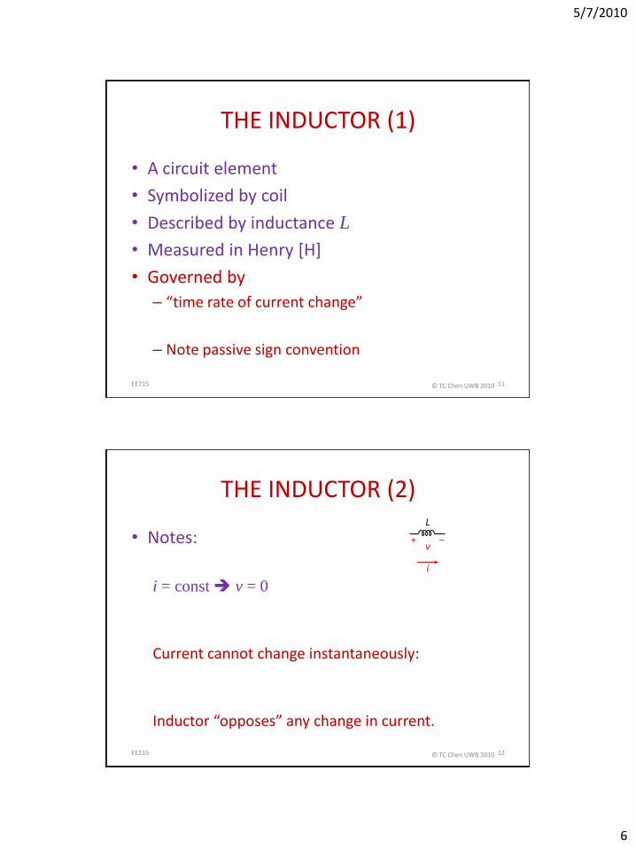
THE INDUCTOR (1)
• A circuit element
• Symbolized by coil
• Described by inductance L
• Measured in Henry [H]
• Governed by
– “time rate of current change”
– Note passive sign convention
11EE215 © TC Chen UWB 2010
THE INDUCTOR (2)
• Notes:
i = const v = 0
Current cannot change instantaneously:
Inductor “opposes” any change in current.
12
v–+
L
i
EE215 © TC Chen UWB 2010
5/7/2010
7
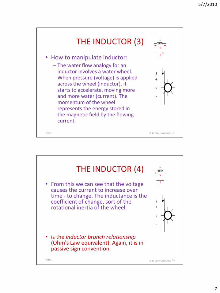
THE INDUCTOR (3)
• How to manipulate inductor:– The water flow analogy for an
inductor involves a water wheel. When pressure (voltage) is applied across the wheel (inductor), it starts to accelerate, moving more and more water (current). The momentum of the wheel represents the energy stored in the magnetic field by the flowing current.
13
v–+
L
i
v
+
-
i
EE215 © TC Chen UWB 2010
THE INDUCTOR (4)
• From this we can see that the voltage causes the current to increase over time - to change. The inductance is the coefficient of change, sort of the rotational inertia of the wheel.
• is the inductor branch relationship(Ohm's Law equivalent). Again, it is in passive sign convention.
14
v–+
L
i
v
+
-
i
EE215 © TC Chen UWB 2010
5/7/2010
8
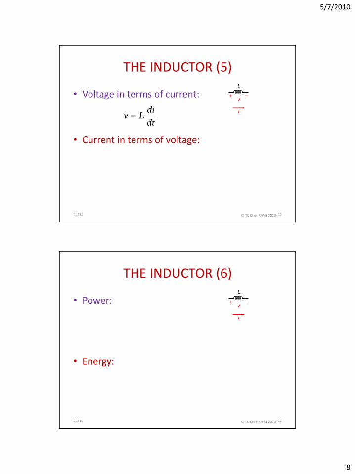
THE INDUCTOR (5)
• Voltage in terms of current:
• Current in terms of voltage:
15
dt
diLv
v–+
L
i
EE215 © TC Chen UWB 2010
THE INDUCTOR (6)
• Power:
• Energy:
16
v–+
L
i
EE215 © TC Chen UWB 2010
5/7/2010
9
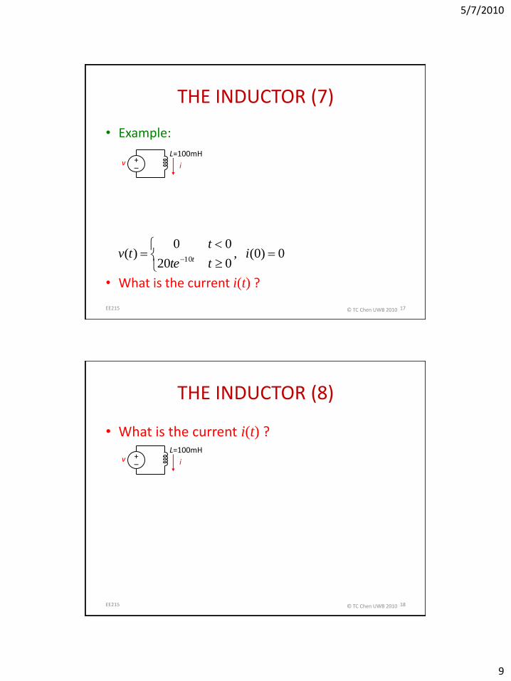
THE INDUCTOR (7)
• Example:
• What is the current i(t) ?
17
0)0( , 020
00)(
10
i
tte
ttv
t
i+–
vL=100mH
EE215 © TC Chen UWB 2010
THE INDUCTOR (8)
• What is the current i(t) ?
18
i+–
vL=100mH
EE215 © TC Chen UWB 2010
5/7/2010
10
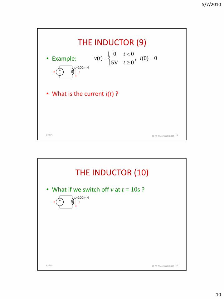
THE INDUCTOR (9)
• Example:
• What is the current i(t) ?
19
0)0( , 0V5
00)(
i
t
ttv
i+–
vL=100mH
EE215 © TC Chen UWB 2010
THE INDUCTOR (10)
• What if we switch off v at t = 10s ?
20
i+–
vL=100mH
EE215 © TC Chen UWB 2010

5/7/2010
11
INDUCTORS IN SERIES (11)
21
v1–+ v2
–+ v3–+ v4
–+
iHj
EE215 © TC Chen UWB 2010
INDUCTORS IN PARALLEL (12)
22
v
–
+
ij Lj
EE215 © TC Chen UWB 2010

5/7/2010
12
THE CAPACITOR (1)
• A circuit element
• Symbolized by two parallel plates
• Described by capacitance C
• Measured in Farad [F]
• Governed by
– “time rate of voltage change”
– Note passive sign convention
23EE215 © TC Chen UWB 2010
THE CAPACITOR (2)
• Notes:
– v = const i = 0
– Voltage cannot change instantaneously:
– “Displacement current”: applied voltage displaces charges in a dielectric.
24
v–+
C
i
EE215 © TC Chen UWB 2010

5/7/2010
13
THE CAPACITOR (3)
• The capacitor stores energy in the electric field. The easy way to make a capacitor is to take two plates of conducting material and separate them with a dielectric (an insulator). The capacitance, C, is then
• where ε is the permittivity of the dielectric (basically how good an insulator it is), A is the area and d is the distance between the plates. This gives rise to the circuit symbol.
25
v–+
C
i
EE215 © TC Chen UWB 2010
THE CAPACITOR (4)
• We can use a water flow analogy to understand the capacitor. It's like a chamber with a rubber membrane stretched across it. Remember that in the water flow analogy, pressure is analogous to voltage. So when charge (water) flows into the capacitor (current flows in), the same amount of water (charge) flows out the other side (current flows through). But the membrane stretches (the electric field becomes stronger between the plates) and so the pressure (voltage) gets higher.
26
v–+
C
i
v
+
-
i i
EE215 © TC Chen UWB 2010
5/7/2010
14
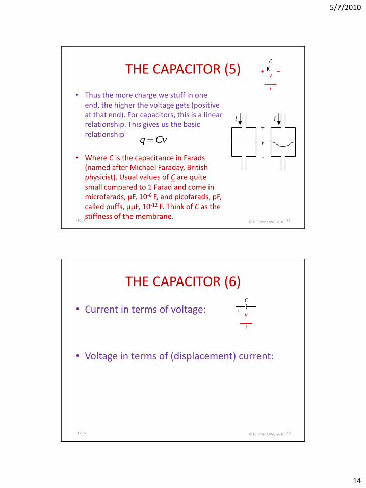
THE CAPACITOR (5)
• Thus the more charge we stuff in one end, the higher the voltage gets (positive at that end). For capacitors, this is a linear relationship. This gives us the basic relationship
• Where C is the capacitance in Farads (named after Michael Faraday, British physicist). Usual values of C are quite small compared to 1 Farad and come in microfarads, μF, 10-6 F, and picofarads, pF, called puffs, μμF, 10-12 F. Think of C as the stiffness of the membrane.
27
v–+
C
i
v
+
-
i i
Cvq
EE215 © TC Chen UWB 2010
THE CAPACITOR (6)
• Current in terms of voltage:
• Voltage in terms of (displacement) current:
28
v–+
C
i
EE215 © TC Chen UWB 2010
5/7/2010
15
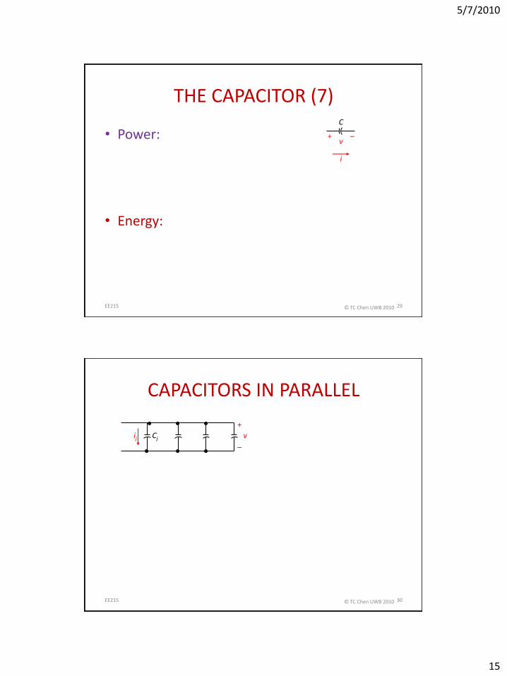
THE CAPACITOR (7)
• Power:
• Energy:
29
v–+
C
i
EE215 © TC Chen UWB 2010
CAPACITORS IN PARALLEL
30
v
–
+
ij Cj
EE215 © TC Chen UWB 2010

5/7/2010
16
CAPACITORS IN SERIES
31
v1–+ v2
–+ v3–+ v4
–+
iCj
EE215 © TC Chen UWB 2010
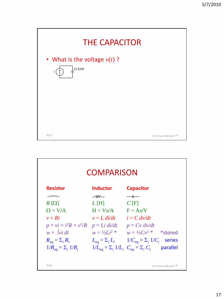
• Example:
• What is the voltage v(t) ?
32
iC=1mF
0)0( ,
s100
s100mA1
00
)(
v
t
t
t
ti
THE CAPACITOR
EE215 © TC Chen UWB 2010
5/7/2010
17
THE CAPACITOR
• What is the voltage v(t) ?
33
iC=1mF
EE215 © TC Chen UWB 2010
COMPARISON
Resistor Inductor Capacitor
R [] L [H] C [F]
= V/A H = Vs/A F = As/V
v = Ri v = L di/dt i = C dv/dt
p = vi = i2R = v2/R p = Li di/dt p = Cv dv/dt
w = vi dt w = ½Li2 * w = ½Cv2 * *stored
Req = i Ri Leq = i Li 1/Ceq = i 1/Ci series
1/Req = i 1/Ri 1/Leq = i 1/Li Ceq = i Ci parallel
34EE215 © TC Chen UWB 2010


![[PPT]Liquid Chromatography Fundamentals - Theory · Web viewLiquid Chromatography Fundamentals - Theory Keywords HPLC, LC, HPLC theory, HPLC fundamentals, teaching HPLC, learning](https://img.pdfslide.tips/doc/110x75/5b1aa2c67f8b9a3c258de481/pptliquid-chromatography-fundamentals-theory-web-viewliquid-chromatography.jpg)