Embed Size (px)
Citation preview

plusN100
-0/29-Power Electronics Dep’t
ELECTRO ELECTRIC SYSTEMS
>> Hyundai industrial inverter
Ø N-Series Inverter Main Function

plusN100
-1/29-Power Electronics Dep’t
Frequency SettingFrequency Setting
Parameter
Set motor input voltage
Set output voltage gain
Set maximum frequency
Set base frequency
name
200/220/230/240 [200V class (SF/ LF type)]
380/400/415/440/460 [400V class (HF type)]
Set output voltage gain of the inverter from 20 to 100%
Settable from 0 to maximum frequency in units of 0.01Hz
frequency at maximum output voltage
description
V--220/
380A53
%10020100.0A32
Hz400A0360.00A04
HzA040.060.00A03
unitMax.Min.defaultN50 & N100
§ inverter parameter
Set Running Frequency

plusN100
-2/29-Power Electronics Dep’t
Set frequency upper/lower limitSet frequency upper/lower limit
Set Running Frequency (Speed)
Parameter
Set frequency lower limit
Set frequency upper limit
name
Set a limit on output frequency greater than zero
frequency at maximum output voltage
description
Hz400A0360.00A39
HzA040.060.00A38
unitMax.Min.defaultN50 & N100
§ inverter parameter
plusN100
-3/29-Power Electronics Dep’t
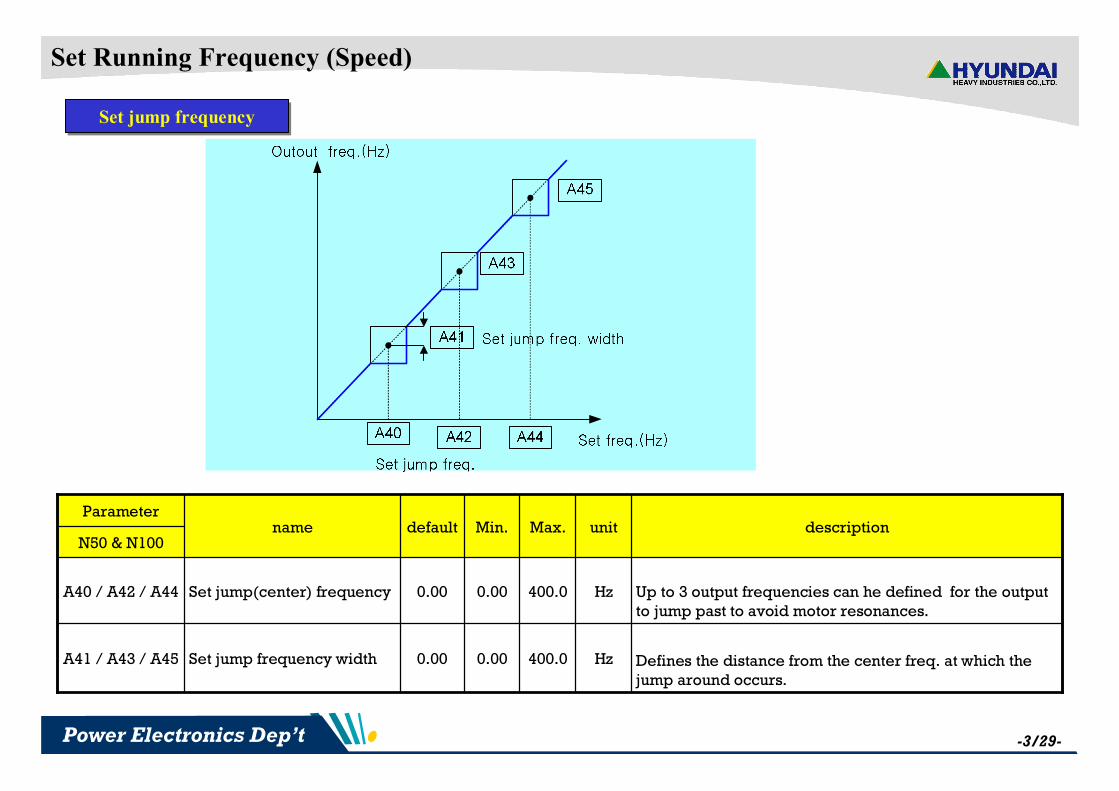
Set jump frequencySet jump frequency
Set Running Frequency (Speed)
Parameter
Set jump frequency width
Set jump(center) frequency
name
Defines the distance from the center freq. at which the jump around occurs.
Up to 3 output frequencies can he defined for the output to jump past to avoid motor resonances.
description
Hz400.00.000.00A41 / A43 / A45
Hz400.00.000.00A40 / A42 / A44
unitMax.Min.defaultN50 & N100

plusN100
-4/29-Power Electronics Dep’t
Set acc./dec. timeSet acc./dec. time
Set acc./dec. time
§ Set acc./dec. time
Parameter
Set running direction
Set dec. time 1
Set acc. time 1
Set output frequency
name
0 : Forward run
1 : Reverse run
time arrive at stop
time arrive at base frequency
A01=0 : keypad potentiometer
A01=1 : control circuit terminal input
A01=2 : standard operation
A01=3 : Remote operator (option-DOP, NOP)
description
-100F04
sec.30000.110.0F03
sec.30000.110.0F02
Hz400.00.00-F01
unitMax.Min.defaultN50 & N100

plusN100
-5/29-Power Electronics Dep’t
Set acc./dec. patternSet acc./dec. pattern
Set acc./dec. pattern
Linear-Curve
S-Curve
U-Curve
Hz
Acc. time
§ Set acc./dec. pattern
Parameter
Deceleration curve selection
Acceleration curve selection
name
0 : linear
1 : S - curve
2 : U - curve
0 : linear
1 : S - curve
2 : U – curve
description
-200A60
-200A59
unitMax.Min.defaultN50 & N100

plusN100
-6/29-Power Electronics Dep’t
Set 2nd acc./dec. timeSet 2nd acc./dec. time
2nd acc./dec.
Settable 2nd acceleration time from 0.1 to 3000sec.30000.010.0Set 2nd acc. timeA54
Settable 2nd deceleration time from 0.1 to 3000sec.30000.010.0Set 2nd dec. timeA55
Two options for switching from 1st to 2nd acc. /dec.
0 : [2CH] intelligent input terminal
1 : transition frequency
-100acc./dec. switching method selection
A56
Parameter
Dec.2 to ded. 1 frequency transition point
acc.1 to acc. 2 frequency transition point
name
output frequency at which dec. 2 switched to dec. 1
output frequency at which acc. 1 switched to acc. 2
description
Hz400.00.000.00A58
Hz400.00.000.00A57
unitMax.Min.defaultN50 & N100

plusN100
-7/29-Power Electronics Dep’t
q parameter
q Select frequency commanding method
1. Keypad potentiometer
A01=0, A02=0
settable frequency command(F01) using potentiometer
2. Control circuit terminal input
i) A01=1, A02=0, C01=13(AT)
SW=off : Voltage Source(0~5V or 0~10V)
SW=on (AT) : Current Source(4~20mA)
3. Standard operation
A01=2, A02=0
settable frequency command(F01) using UP/DONW key
CM1 6 5 4 3 2 1 P24 H O OI L FM CM2 11 12
SW = AT
Voltage Source
Current Source
Frequency commanding
ii) A01=1, A02=0, C01≠13(AT)
Voltage Source + Current Source
0 : keypad potentiometer
1 : control circuit terminal input(analog voltage or current)
2 : standard operation
3 : Remote operator (option-DOP, NOP)
-300
Frequency
commanding
A01
Parametername descriptionunitMax.Min.default
N50 & N100

plusN100
-8/29-Power Electronics Dep’t
Set analog input for freq. commandSet analog input for freq. command
N50 & N100
0 : 0~5V input
1 : 0~10V input -100
set external voltage input frequency selection
A65
Two options;
0 : start at start freq. (=A05) 1 : start at 0Hz-110
set external frequency start pattern
A09
set external frequency end rate
set external frequency start rate
set external frequency end
set external frequency start
name
Ending point (offset) for the active analog input range
starting point (offset) for the active analog input range
Output freq. at 10V or 20mA 10V(20mA)
Output freq. at 0V or 4mA
description
%100.00.0100.0A08
%100.00.00.0A07
HzA040.000.00A06
HzA040.000.00A05
unitMax.Min.defaultParameter
External frequency command

plusN100
-9/29-Power Electronics Dep’t
q test for frequency command using analog voltage input
)0708(
)07()0506(05
AA
AAAAAF in
out-
-´-+=
Input voltage< A07 ; output freq. = A05
Input voltage >= A08 : output freq. = A06
60.0010.0
55.009.0
50.008.0
45.007.0
40.006.0
35.005.0
30.00 4.0
25.003.0
20.002.0
20.001.0
20.000.0
Freq. command (FO1)
(Hz)
Input voltage
(V)
1A65
0A09
100.0A08
20.0A07
0.00A06
20.00A05
Setting valueparameter
q ex) Parameter setting Test value

plusN100
-10/29-Power Electronics Dep’t
q test for frequency command using analog current input
)0708(
)07()0506(05
AA
AAAAAF in
out-
-´-+=
Input voltage< A07 ; output freq =0
Input voltage >= A08 : output freq. =A06
- C01=13(AT), S/W=0N
50.0020.0
40.0016.8
30.0013.6
20.0010.4
10.007.2
0.005.6
0.004.0
Freq. command (FO1)
(Hz)
Input current
(mA)
1A65
1A09
100.0A08
20.0A07
50.00A06
10.00A05
Setting valueparameter
q ex)
Parameter setting Test value
plusN100
-11/29-Power Electronics Dep’t
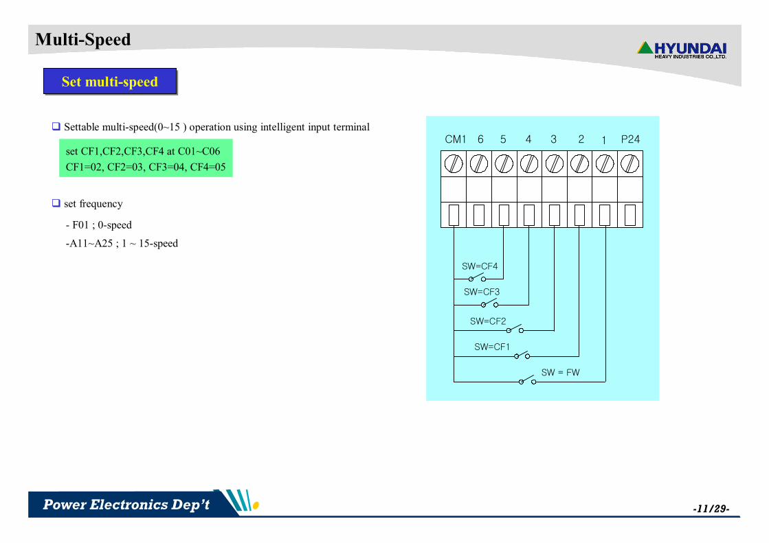
Multi-Speed
Set multi-speed Set multi-speed
CM1 6 5 4 3 2 1 P24
SW = FW
SW=CF1
SW=CF2
SW=CF3
SW=CF4
q Settable multi-speed(0~15 ) operation using intelligent input terminal
set CF1,CF2,CF3,CF4 at C01~C06
CF1=02, CF2=03, CF3=04, CF4=05
q set frequency
- F01 ; 0-speed
-A11~A25 ; 1 ~ 15-speed

plusN100
-12/29-Power Electronics Dep’t
11111111
FW
SW1
SW2SW3SW4SW5
CF1CF2CF3CF4
A175011107-speedA164001106-speedA153010105-speedA142000104-speedA131511003-speedA121001002-speedA11510001-speedF01200000-speed
para-
meter
setting
Value
(Hz)
Intelligent input
multi-speedpara-
meter
setting
Value
(Hz)
Intelligent input
multi-speedSW1
SW2SW3SW4SW5
FWCF1CF2CF3CF4
A2521111115-speedA2451011114-speedA23151101113-speedA22251001112-speedA21351110111-speedA20451010110-speedA1955110019-speedA1860100018-speed
q ex) operation of 16-multispeed
On : 1Off : 0
0
0
0
0
1
0
0
0
0
1
0
0
1
1
0
0
0
0
1
0
1
1
1
1

plusN100
-13/29-Power Electronics Dep’t
Jogging operation
Set jogging operationSet jogging operation
q set the parameter for jogging operation
q Free-run stop
Test waveform using FM output-terminal
q deceleration stop
Set parameter : A26=10.0, A27=1C03=6, C17=2, F02=F03=5.0
q DC braking stop
Set parameter : A26=10.0, A27=2A34=1.00Hz, A35=0.5A36=10.0, A37=1.0C03=6, C17=2, F02=F03=5.0
Set parameter : A26=10.0, A27=0,C03=6, C17=2, F02=F03=5.0
N50 & N100
Jogging stop operation selection
Jogging frequency
name
0 : Free-run stop
1 : deceleration stop
2 : DC braking stop
jogging signal at intelligent input terminal
C01~C06 = 6(jogging operation)
description
-200A27
Hz10.000.500.50A26
unitMax.Min.defaultParameter

plusN100
-14/29-Power Electronics Dep’t
Torque boost
Torque boostTorque boost
q torque boost function
-Boost starting torque at insufficiency starting torque
in case of V/f control
-Be aware that excessive torque boost can cause
motor damage and inverter trip.
Set manual torque boost voltage%50.005.0Manual torque boost settingA29
N50 & N100
Manual torque boost frequency setting
torque boost mode selection
name
0 : manual torque boost
1 : automatic torque boost
description
%100010.0A30
-100A28
unitMax.Min.defaultParameter

plusN100
-15/29-Power Electronics Dep’t
V/F characteristics
Set control methodSet control method
V
Hz
Constant torque
100%
20%
A32
N50 & N100
V/F gain
Control method
name
Output voltage gain
0 : constant torque
1 : reduced torque (reduction of the 1.7th power)
2 : sensorless vector control
description
%10020100.0A32
-200A31
unitMax.Min.defaultParameter
constant torqueconstant torque reduced torquereduced torque
A31=0, A32=50.0 A31=1, A32=100.0

plusN100
-16/29-Power Electronics Dep’t
DC braking
DC braking DC braking
Set the freq. at which dc braking occursHz10.00.00.50dc braking freq.A34
0 : dc braking disable
1 : dc braking enable-100
dc braking function selection
A33
delay time from dc braking freq. to starting dc braking
Sec5.00.10.0dc braking output delay time
A35
N50 & N100
dc braking time
dc braking force
name
Duration for dc braking
description
sec10.00.10.0A37
%50010.0A36
unitMax.Min.defaultParameter

plusN100
-17/29-Power Electronics Dep’t
PID Control
PID feedback controlPID feedback control
0 : PID control disable
1 : PID control enable-100PID function selectionA46
Sec100.00.010.0I gainA48
%1000.110.0P gainA47
Sec100.00.00.0D gainA49
N50 & N100
Feed-back method
PID scale factor
name
set source of feedback method
0 : current input
1 : voltage input
Set PID scale factor (multiplier)
description
-100A51
-10000.1100.0A50
unitMax.Min.defaultParameter

plusN100
-18/29-Power Electronics Dep’t
AVR function
Automatic Voltage RegulationAutomatic Voltage Regulation
- AVR : maintain inverter output voltage in spite of change input voltage
N50 & N100
Motor input voltage
AVR function selection
name
200/220/230/240 (200V class)
380/400/415/440/460 (400V class)
0 : constant ON
1 : constant OFF
2 : OFF during deceleration
description
V240/
460
200/
380
220/
380A53
-200A52
unitMax.Min.defaultParameter

plusN100
-19/29-Power Electronics Dep’t
Restart
Restart for instantaneous power failureRestart for instantaneous power failure
0 : alarm output after trip
1 : restart at 0Hz
2 : resume operation at frequency matching
3 : resume previous frequency after frequency matching,
then decelerate to stop and display trip
-300Selection of
restart modeb01
N50 & N100
Reclosing stand by after instantaneous power failure recovered
Allowable instantaneous power failure time
name
Time delay after under voltage condition goes
away, before the inverter runs motor again
amount of time a power input under voltage can occur without tripping the power failure alarm
description
sec30.31.0b03
sec1.00.31.0b02
unitMax.Min.defaultParameter
q restart at 0Hz q resume operation at frequency matching
q resume previous frequency after frequencymatching, then decelerate to stop & trip

plusN100
-20/29-Power Electronics Dep’t
Overload Restriction
Overload RestrictionOverload Restriction
0 : over-load/over-voltage restriction OFF
1 : over-load restriction ON
2 : over-voltage restriction ON
3 : over-load/over-voltage restriction ON
-301over-load/over-voltage restriction mode selection
b06
N50 & N100
over-load restriction constant
over-load restriction level
name
Set the deceleration rate
set the level for overload restriction
description
sec30.00.10.1b08
%20020125b07
unitMax.Min.defaultParameter

plusN100
-21/29-Power Electronics Dep’t
Software Lock
Software LockSoftware Lock
N50 & N100
Software Lock mode selection
name
0 : All parameters except b09 are locked when [SFT]
terminal ON
1 : All parameters except b09, F01 are locked when
[SFT] terminal ON
2 : All parameters except b09 are locked
3 : All parameters except b09, F01 are locked
description
-300b09
unitMax.Min.defaultParameter

plusN100
-22/29-Power Electronics Dep’t
Parameter Initialization
Parameter InitializationParameter Initialization
N50 & N100
Initialization mode selection
name
0 : trip history clear
1 : parameter initialization
description
-100b12
unitMax.Min.defaultParameter

plusN100
-23/29-Power Electronics Dep’t
FRS cancellation mode
Resume on Free Run Stop cancellation modeResume on Free Run Stop cancellation mode
q test 1 : Restart from 0Hz
- b16=0, C01=0, C05=9
q test 2 : Restart from frequency detection
- b16=1, C01=0, C05=9
N50 & N100
Resume on Free Run Stop cancellation mode selection
name
0 : Restart from 0Hz
1 : Restart from frequency detected from real speed
of motor
description
-100b16
unitMax.Min.defaultParameter

plusN100
-24/29-Power Electronics Dep’t
Intelligent Input Terminals
1st multi-speed-1402Intelligent Input Terminal 3 settingC03
2nd multi-speed-1403Intelligent Input Terminal 4 settingC04
reverse run-1401Intelligent Input Terminal 2 settingC02
analog input current/voltage selection-1408Intelligent Input Terminal 5 settingC05
forward run-1400Intelligent Input Terminal 1 settingC01
reset-14014Intelligent Input Terminal 6 settingC06
DescriptionunitMax.Min.defaultnameparameter
〃-100Input Terminal 3 a/b contact settingC09
〃-100Input Terminal 4 a/b contact settingC10
〃-100Input Terminal 2 a/b contact settingC08
〃-100Input Terminal 5 a/b contact settingC11
0 : a-contact (Normal Open) [NO]
1 : b-contact (Normal Close) [NC]-100Input Terminal 1 a/b contact settingC07
〃-100Input Terminal 6 a/b contact settingC12
DescriptionunitMax.Min.defaultnameparameter
q Intelligent Input Terminals function setting
-0 : FW (forward run)
-1 : RV (reverse run)
-2 : CF1 (1st multi-speed)
-3 : CF2 (2nd multi-speed)
-4 : CF3 (3rd multi-speed)
-5 : CF4 (4th multi-speed)
-6 : JG (jogging operation)
-7 : SET (2nd function setting)
-8 : 2CH (2-stage acc./dec. )
-9 : FRS (free run stop)
-10 : EXT (external trip)
-11 : USP (unattended start protection)
-12 : SFT (software lock)
-13 : AT (analog input current/voltage selection)
-14 : RS (reset)

plusN100
-25/29-Power Electronics Dep’t
Intelligent Output Terminals
q Intelligent Output Terminals function setting
-0 : RUN (Run signal)
-1 : FA1 (Frequency arrival signal ; command arrival)
-2 : FA2 (Frequency arrival signal ; setting frequency or more)
-3 : OL (Overload advance notice signal)
-4 : OD (Output deviation for PID control)
-5 : AL (alarm signal)
Hz400.00.000.00Dec. arrival signal freq.C22
Hz400.00.000.00Acc. arrival signal freq.C21
Set overload signal level 50%~200% of inverter rated current
%20050100.0Overload advance notice signal
C20
0 : a-contact (Normal Open) [NO]
1 : b-contact (Normal Close) [NC]-100
Terminal 11 a/b contactsetting
C15
〃-100Terminal 12 a/b contactsetting
C16
-500Output Terminals 12 settingC14
%100.00.010.0PID Deviation level C23
-501Output Terminals 11 settingC13
DescriptionunitMax.Min.defaultnameparameter

plusN100
-26/29-Power Electronics Dep’t
q test 1 : RUN signal output q test 2 : FA1
CH.1 output freq.CH.2 terminal 11 output signal
(0V: ON, High : Off)
parameter : C13=0, C15=0 parameter : C13=1, C15=0
q test 3 : FA2 q test 4 : OL
parameter : C13=2, C15=0, C21=30.0, C22=40.0 parameter : C4=3, C16=0, C20=100.0
F01
C21
C22
Hz
signal
plusN100
-27/29-Power Electronics Dep’t
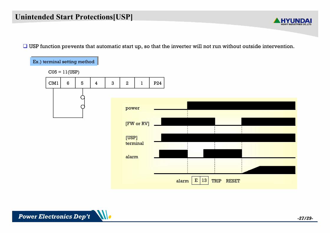
Unintended Start Protections[USP]
Ex.) terminal setting methodEx.) terminal setting method
q USP function prevents that automatic start up, so that the inverter will not run without outside intervention.
CM1 6 5 4 3 2 1 P24
C05 = 11(USP)
power
[FW or RV]
[USP] terminal
alarm
alarm 13E TRIP RESET
plusN100
-28/29-Power Electronics Dep’t
Auto Tuning
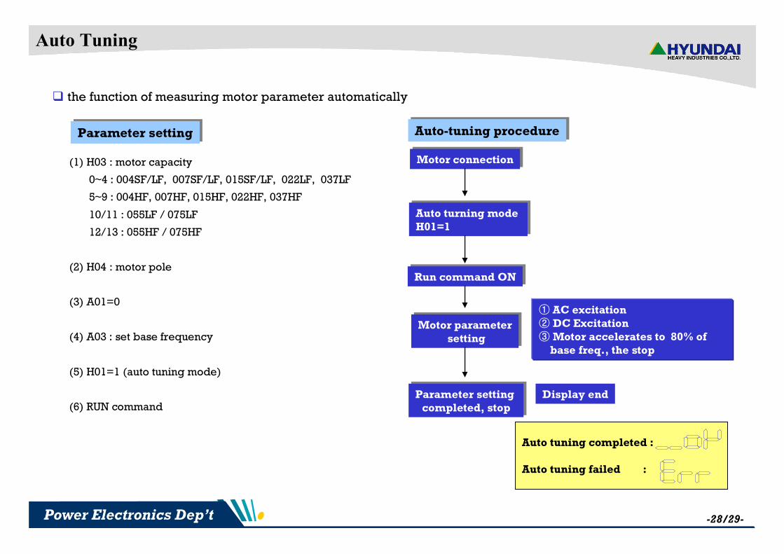
q the function of measuring motor parameter automatically
Parameter settingParameter setting
(1) H03 : motor capacity
0~4 : 004SF/LF, 007SF/LF, 015SF/LF, 022LF, 037LF
5~9 : 004HF, 007HF, 015HF, 022HF, 037HF
10/11 : 055LF / 075LF
12/13 : 055HF / 075HF
(2) H04 : motor pole
(3) A01=0
(4) A03 : set base frequency
(5) H01=1 (auto tuning mode)
(6) RUN command
Auto-tuning procedureAuto-tuning procedure
Motor connectionMotor connection
Auto turning mode H01=1
Auto turning mode H01=1
Run command ONRun command ON
Motor parametersetting
Motor parametersetting
Parameter setting completed, stop
Parameter setting completed, stop
① AC excitation② DC Excitation③ Motor accelerates to 80% of
base freq., the stop
Display end
Auto tuning completed :
Auto tuning failed :

plusN100
-29/29-Power Electronics Dep’t
Error Code
Ø Protective Code (N50 & N100) ;