Embed Size (px)
Citation preview
臺灣 2011年8月24~25日
18-Aug-11 1
APEC 2011Advanced Control Architectures for
Intelligent Microgrids
Josep M. Guerrero, Prof.
Institute of Energy Technology, Aalborg University

Outline
1 Microgrids systems
2 Control of VSIs for microgrids
3 Droop control and virtual impedance concept
4 Hierarchical control of microgrids
5 Power quality in microgrids
6 DC microgrids

Centralized vs Distribuited Power Systems
General advantages of the DPS:
• Redundancy
• Modularity
• Fault tolerance
• Efficiency
• Reliability
• Easy maintenance
• Smaller size
• Lower design cost

Microgrid operation
Microgrid operation modes:• Grid connected
• Islanded
Typical structure of a flexible microgrid
. . . .
PV
panel system
PCC
UPS
Common
AC bus
Distributed loads
Intelligent
Bypass
Switch
(IBS)
Wind turbine
Inverters
Renewableenergy sources
Utility Grid
18-Aug-11 4

Microgrid operation modes• Operation modes and transfers of the flexible microgrid and STS
grid status supervisory
• Virtual inertias are often implemented through control loops known as droop method.
• Intelligent microgrids are required to integrate DG, DS, and dispersed loads into the future smart grid.
• Microgrids should be able to operate autonomously but also interact with the main grid.
• CSI units are normally used for PV or WT systems that require maximum power point tracker algorithms.
• VSI units are used for storage energy systems to support the voltage and frequency of the microgrid in island mode.
Microgrid operation
18-Aug-11 5
Microgrid operation
18-Aug-11 6
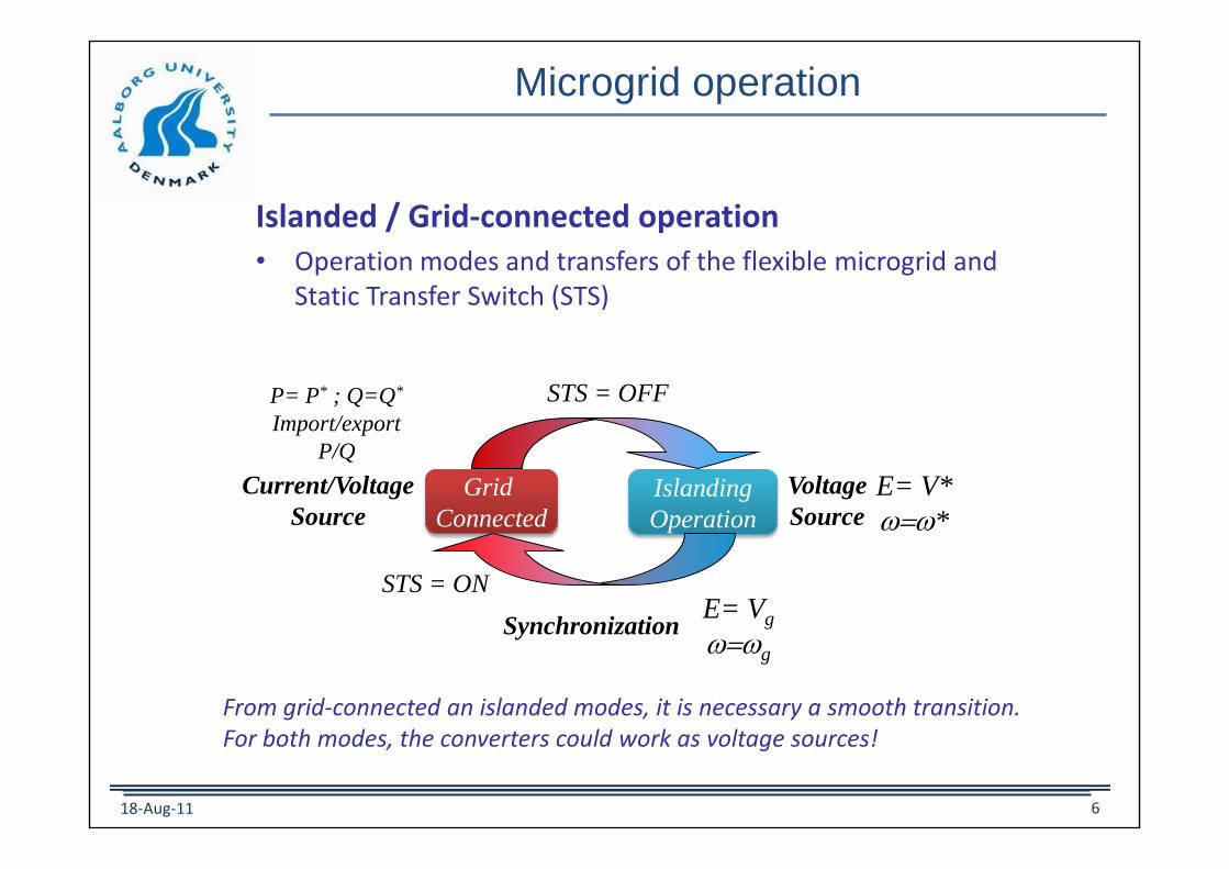
Islanded / Grid-connected operation• Operation modes and transfers of the flexible microgrid and
Static Transfer Switch (STS)
From grid-connected an islanded modes, it is necessary a smooth transition.For both modes, the converters could work as voltage sources!
STS = OFF
STS = ON
Grid
Connected
E= Vg
w=wg
E= V*
w=w*
P= P* ; Q=Q*
Import/export
P/Q
Islanding
Operation
Synchronization
Current/Voltage
Source
Voltage
Source

Microgrid operation
Islanded operation• Preplanned islanded operation: If any events in the main grid are
presented, such as long-time voltage dips or general faults, among others, islanded operation must be started.
• Nonplanned islanded operation: If there is a blackout due to a disconnection of the main grid, the microgrid should be able to detect this fact by using proper algorithms.
18-Aug-11 7

Microgrid operation
Islanded operation• Voltage and frequency management: The system acts like a
voltage source, controlling power flow through voltage and frequency control loops adjusted and regulated as reference within acceptable limits.
• Supply and demand balancing: In grid-connected mode, the frequency of the DG units is fixed by the grid. Changing the setting frequency, new active power set points that will change the power angle between the main grid and the microgrid can be obtained.
• Power quality: The power quality can be established in two levels. The first is reactive power compensation and harmonic current sharing inside the microgrid, and the second level is the reactive power and harmonic compensation at the PCC; thus, the microgridcan support the power quality of the main grid.
18-Aug-11 8

Microgrid Configurations
• AC-DC Hybrid MicrogridHierarchy of loads
Source: SMA
18-Aug-11 9

Microgrid Configurations
Connection interface (CI)
18-Aug-11 10

11
Inner control loops
To Load/grid
VSI control strategy
av
bv
cv
lbi
lci
bC cC
Ccv
Cbv
Cav
PWM
abc
laiaL
bL
cL
obL
ocL
aC
n
li Cv
Current P + Resonant Controller
abc
Voltage P + Resonant Controller
refv
Inner Loops
obi
Three Phase
Reference
Generator
oci
oaioaL
dcv
abc
*i
pVk
2 22iV
c os
k s
s w w
pIk
22
5,7,11... 2 o
niHh
h c h
k s
s s ww=
2 22iI
c os
k s
s w w
22
5,7,11... 2 o
nvHh
h c h
k s
s s ww=
abc
x
Power stage and control of a 3 phase VSI with LCL filter
1 1/ 2 1/ 22 / 3· ·
0 3 / 2 3 / 2
a
b
c
vv
vv
v
=
Alpha-beta transformation

12
Block diagram of the closed-loop VSI.
2 2
1( ) ( )
( ) ( ) 1 ( ) ( ) 1
v i PWMc ref o
v i PWM v i PWM
G s G s G CsV V iLCs Cs G s G s G LCs Cs G s G s G
=
1
sL
abcv
PWMG oi
li
ci1
sC
PWM inverter L-C Filter P + Resonant Controllers
cvref
v
dcv
( )vG s ( )iG s
*i
22 2 2
5,7,11
( )v pV
o
rV hV
ho
G s kk sk s
s s hw w=
=
22 2 25,7,11
( )i pI
o
hIrI
ho
G s kk sk s
s s hw w=
=
1
1 1.5PWM
s
GT
=
Inner control loops
Voltage tracking Output impedance
Voltage control loop Current control loop
Computation delay

13
Bode diagram of the tracking voltage transfer function Gv(s)
Inner control loops
Objective: closed-loop band pass filter characteristics with 0dB, 0º
P+R
P+R+H
14
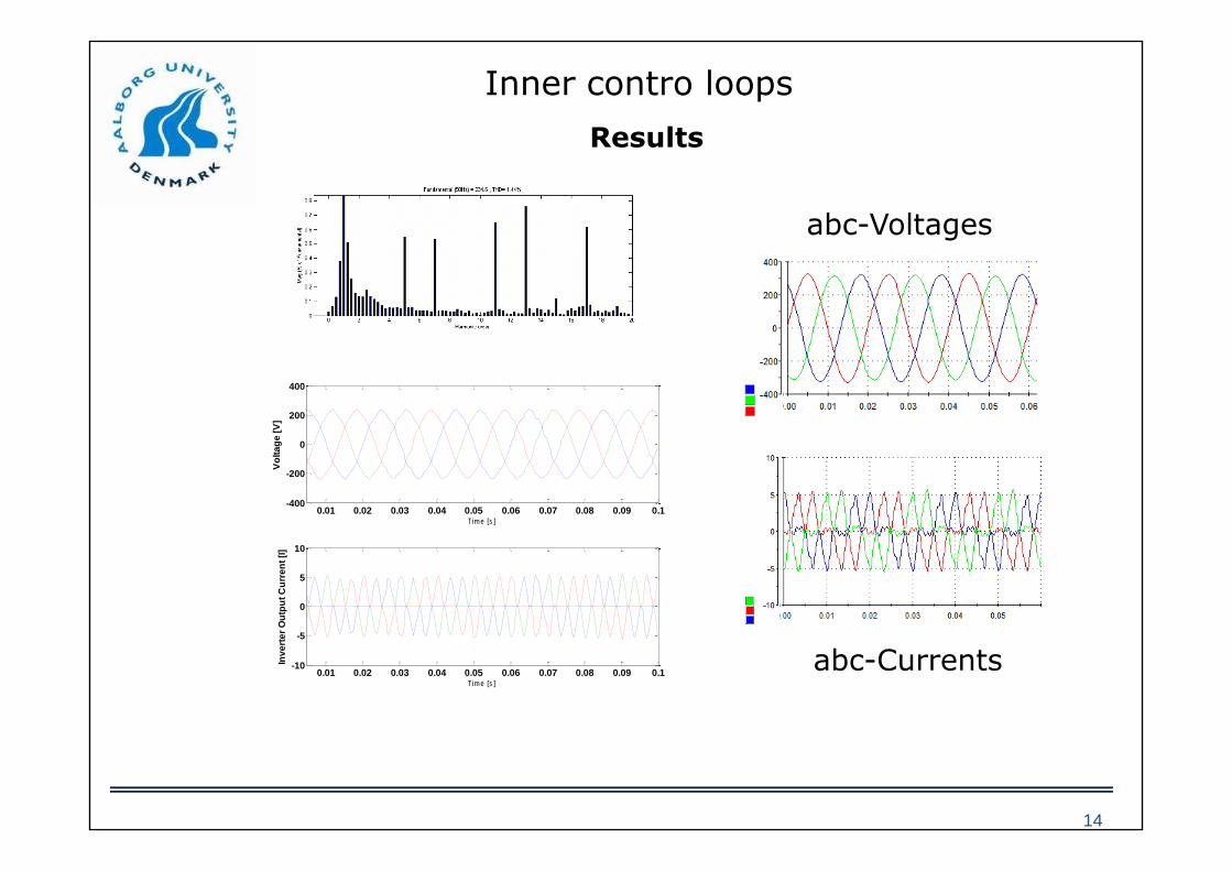
Inner contro loops
0.01 0.02 0.03 0.04 0.05 0.06 0.07 0.08 0.09 0.1-400
-200
0
200
400
Time [s]
Vo
lta
ge
[V
]
0.01 0.02 0.03 0.04 0.05 0.06 0.07 0.08 0.09 0.1-10
-5
0
5
10
Time [s]
Inv
ert
er
Ou
tpu
t C
urr
en
t [I
]
Results
abc-Voltages
abc-Currents

Control of parallel converters
Master-slave control
• Voltage source: grid forming units
• Current source: MPPT units. WT and PV
In this system is not necessary current sharing!
dcv av
bv
cv
Lbi
Lci
aCbC cC
n
Ccv
Cbv
Cav
abc
Li Cv
SVM
Voltage ResonantController
Current Resonant Controller
abc
Lai
cL
bL
aLoaL
obL
ocL
2oaL
2obL
2ocL
obi
oci
oai
dcv
2av
2bv
2cv
2aC 2bC 2cC
n
2Cbv
2Cav2L bi
2L ci
2L ai 2aL
2bL
2cL
2Ccv
2obi
2oci
2oai
Load
SVM
abc
Three Phase Reference
Generator
abc
abc
Current Resonant Controller
MPPTMPPT
Energy Storage System PV/WT
18-Aug-11 15

Control of parallel converters
Woo-Cheol Lee “A Master and Slave Control Strategy for Parallel Operation of Three-Phase UPS Systems with Different Ratings”
. . . Load
VoltageSource
(Master)
Current ControlledSources (Slave)
Im IoIsnIs2Is1
Master-slave control
18-Aug-11 16

Droop control for AC MGs
Droop control of AC systems
sinVE
PX
=Active power Reactive power
mP= *www*
P
w
w
Pmax
Frequency droop
*E E nQ= E*
Q
E
Qmax
Amplitude droop
E 11 E 22V0o
DG Inverter 1 Load
112
DG Inverter 2
1X 2X
1i 2i
18-Aug-11 17

Droop control for AC MGs
P. Kundur
• Synchronous generator
Equation of motion:
Inertia constant:
m e
dJ T T
dt
w=
stored energy E
H srating power P
= = with 21
2E Jw=
rw1
2Hs
Tm
eT
aT
eT
rw
aT
Tm
s
H
Laplace Operator
Mechanical torque (pu)
Electrical torque(pu)
Accelerating torque (pu)
Inertia constant (MW-Sec/MVA)
Rotor speed deviation (pu)
Inertias in power systems
18-Aug-11 18
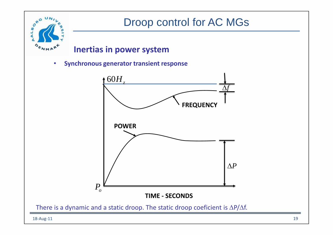
Droop control for AC MGs
• Synchronous generator transient response
oP
P
POWER
FREQUENCY
f60 zH
TIME - SECONDS
Inertias in power system
There is a dynamic and a static droop. The static droop coeficient is P/f.
18-Aug-11 19

Virtual synchronous generators
• Inverters that mimic synchronous converters
• Kawamura’s approach (2005)
High Reliability and High Performance Parallel-Connected UPS System with Independent ControlEduardo Kazuhide Sato
18-Aug-11 20
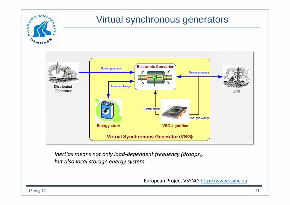
Virtual synchronous generators
European Project VSYNC: http://www.vsync.eu
Inertias means not only load-dependent frequency (droops),but also local storage energy system.
18-Aug-11 21
Droop control for AC MGs
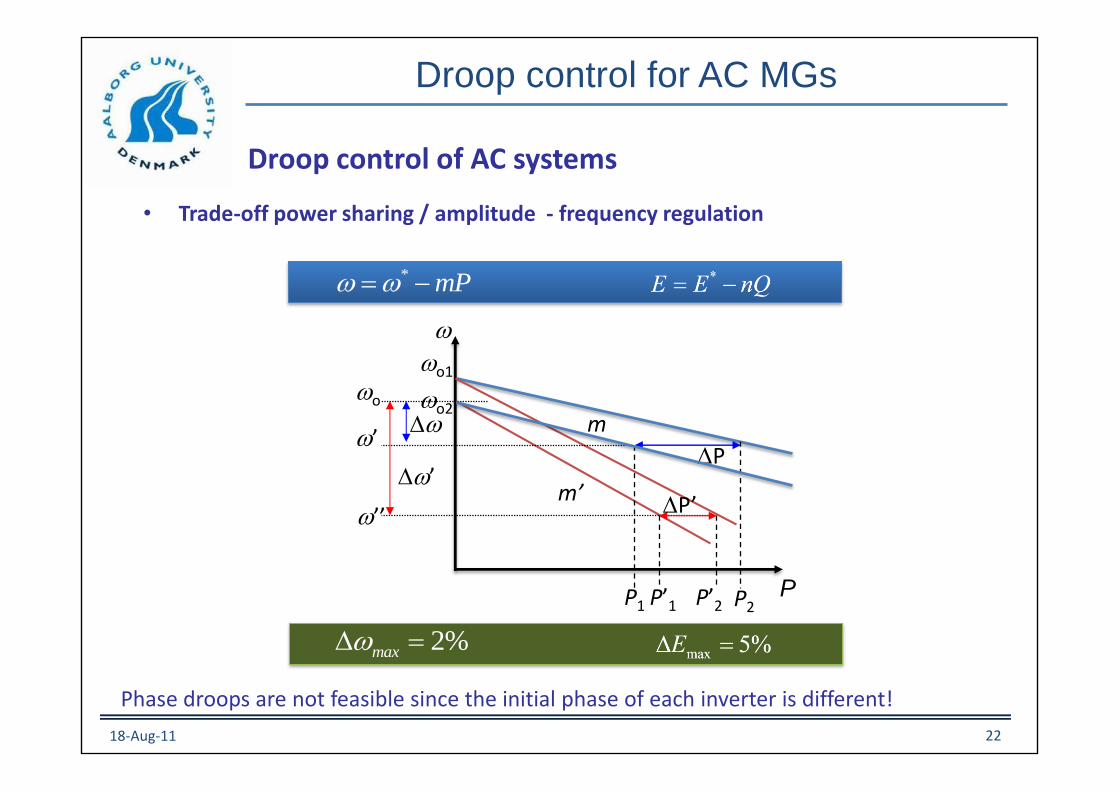
Droop control of AC systems
• Trade-off power sharing / amplitude - frequency regulation
Phase droops are not feasible since the initial phase of each inverter is different!
18-Aug-11 22
wo1
wo2
PP’1 P’2P1 P2
m
m’
P
P’w’
w
w
wo
w’
w’’
* mPw w=
2%maxw =
Droop control for AC MGs
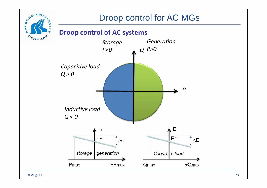
Droop control of AC systems
P
Q
GenerationP>0
StorageP<0
Capacitive loadQ > 0
Inductive loadQ < 0
18-Aug-11 23

Droop control for AC MGs
• Study of P/Q flow in function of the output impedance
Generalized droop control
The R – V virtual resistance in a DC microgrid can be see as Q – V droop in an inductiveAC microgrid. The w – P droop is added to synchronize the system.
Z
E
VSI S P jQ=
0ºV
2
2
cos cos
sin sin
EVP
Z
EVQ
Z
V
Z
V
Z
=
=
By using the Park transformation, the droop method functions become
18-Aug-11 24
Virtual Impedance
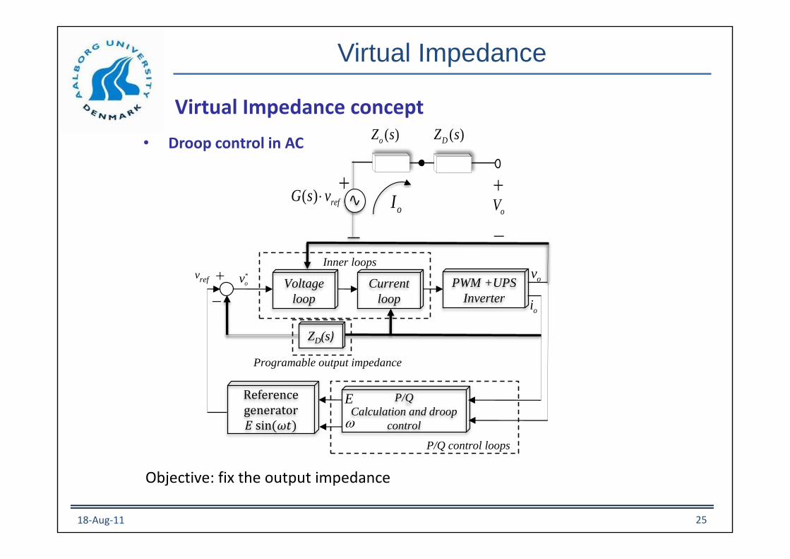
• Droop control in AC
Objective: fix the output impedance
Virtual Impedance concept
oI
( )oZ s ( )DZ s
oV
( ) refG s v
ov
oi
P/Q
Calculation and droop
control
PWM +UPS
Inverter
Current
loop
Voltage
loop
ZD(s)
Reference generator
Programable output impedance
refv
Inner loops
E
w
*
ov
P/Q control loops
18-Aug-11 25
Virtual Impedance
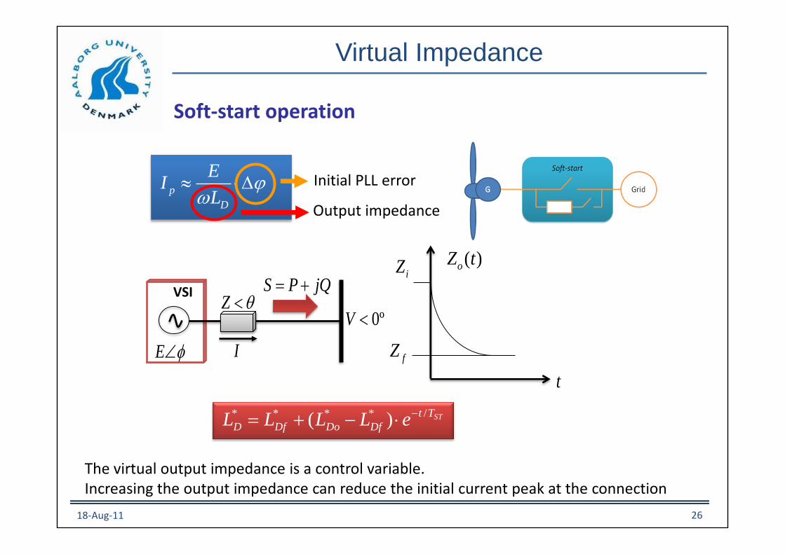
p
D
EI
L
w
STTt
DfDoDfD eLLLL/**** )(
=
Initial PLL error
Output impedance
t
( )oZ tiZ
fZ
Z
E
VSI S P jQ=
0ºV
I
Soft-start operation
The virtual output impedance is a control variable.Increasing the output impedance can reduce the initial current peak at the connection
18-Aug-11 26

Virtual Impedance
Hot-swap capability
This capability allow us to connect DGs without stop the microgrid, formantainance reasons.
4 DG units microgrid
Virtual impedance
Output currentsBefore the connection, a PLL have to synchronize the DG with the MG.A the connection the virtual impedance is high to reduce the initial current peak.
18-Aug-11 27

Low voltage ride-though
Reactive power control of a grid-connected DG.
Low voltage ride-through
Trade-off during voltage dips: 1) voltage follower (Q=0) 2) stiff voltage source (Q high)
18-Aug-11 28
E
E*E
nomQQ
nomQ
*E E nQ=
Capacitive load Inductive loadLRE
GQ
GL
0ºgV
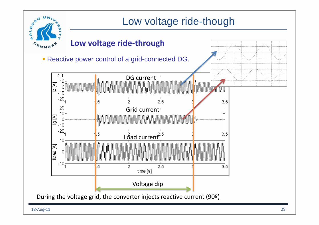
Low voltage ride-though
Reactive power control of a grid-connected DG.
Low voltage ride-through
DG current
Grid current
Load current
Voltage dip
During the voltage grid, the converter injects reactive current (90º)
18-Aug-11 29

Low voltage ride-though
Reactive power control of a grid-connected DG.
Low voltage ride-through
Active power remains constant (to the load). Reactive power is injected to mantain thevoltage inside the droop characteristic.
18-Aug-11 30
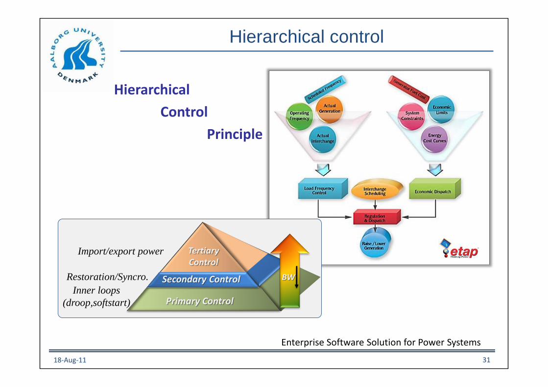
Hierarchical control
Hierarchical
Control
Principle
Enterprise Software Solution for Power Systems
Primary Control
TertiaryControl
Secondary Control BW
Import/export power
Restoration/Syncro.
Inner loops
(droop,softstart)
18-Aug-11 31
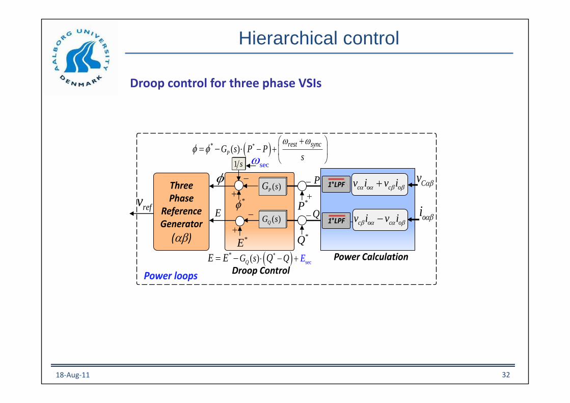
Hierarchical control
Droop control for three phase VSIs
** ( )P
rest syncG s P P
s
w w
=
P
QE
Three Phase
Reference Generator
()
c o c ov i v i
c o c ov i v i 1°LPF
Cv
oi
Power Calculation
*
*E
Droop Control
( )QG s
( )P sG 1°LPF
*
sec
* ( )QG Es QE E Q =
*P
*Q
Power loops
secw1 s
refv
18-Aug-11 32

Hierarchical control
Virtual impedance control for three phase VSIs
aC
oi oi
PWM
abc
C
Cv
vR vLw
vRvLw
refv Virtual Impedance loop
vv
Current P + Resonant Controller
Voltage P + Resonant Controller
oabci
Inner loops
L
labcioL
1VSI
V v o v o
V v o v o
V R i L i
V R i L i
w
w
=
=
2
1 ( ) ( ) ( ) ( )( )
( ) ( ) ( ) 1
v i PWM D
o o
v i PWM
G s G s G s Z sCsZ s L s
LCs Cs G s G s G s
=
( ) refG s voI
( )oZ s ( )DZ s
vV
( ) ( ) ( )out ref o ov s G s v Z s i=
18-Aug-11 33
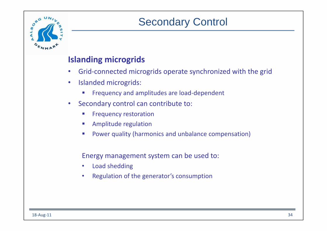
Islanding microgrids• Grid-connected microgrids operate synchronized with the grid
• Islanded microgrids:
Frequency and amplitudes are load-dependent
• Secondary control can contribute to:
Frequency restoration
Amplitude regulation
Power quality (harmonics and unbalance compensation)
Energy management system can be used to:
• Load shedding
• Regulation of the generator’s consumption
Secondary Control
18-Aug-11 34

Secondary Control in Electric Power Systems
PowerController
Load
DG3
PowerController
Load
DG2 PowerController
Load
DG1
Grid
This area consists of DG’s with thedroop control. In island mode thefrequency can droop down!
18-Aug-11 35

Secondary Control in Electric Power Systems
Source: UCTE. A1 – Appendix 1: Load-Frequency Control and Performance
18-Aug-11 36
Secondary Control for Microgrids
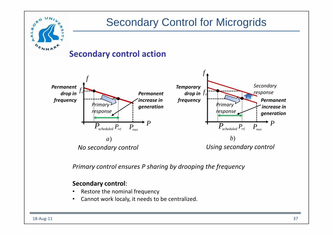
Secondary control action
Primary control ensures P sharing by drooping the frequency
Secondary control:• Restore the nominal frequency• Cannot work localy, it needs to be centralized.
f
0f
refPscheduledP
)a
maxP
No secondary control
Primaryresponse
P
Permanentdrop in
frequencyPermanentincrease in generation
f
0f
refPscheduledP
)b
maxP
Using secondary control
Primaryresponse
P
Temporarydrop in
frequency Permanentincrease in generation
Secondaryresponse
18-Aug-11 37

Secondary Control for Microgrids
Secondary control Implementation
Low bandwidth
communications
Primary control
P/Q Droopcontrol
Secondary control
Frequency &Voltage
restoration loop
wMG
wMG
Gw(s)
EMG
E*MG
GE(s)
vref
ZD(s)
Virtual impedance
dE
dwM
i
c
r
o
g
r
i
d
wMG / EMG
measurements
+
+
_
_
ov
oi
Current
loop
Voltage
loop
Inner loops
PWM
+UPS
Inverter_
Primary control
P/Q Droopcontrol
vref
ZD(s)
Virtual impedance
ov
oi
Current
loop
Voltage
loop
Inner loops
PWM
+UPS
Inverter_
+
ws
Secondary control is located in the Microgrid Central Controller measure frequency and voltage. The output of the control is send through communications to adjust the referenceof the local primary controllers (droops).
18-Aug-11 38

Microgrid synchronization with the grid
Synchronization is not necessary to be fast. Slow (to avoid unstability problems) butwell accurate (allowing seamless transition to grid-connected mode).
18-Aug-11 39

Tertiary Control
Tertiary control for AC microgrids• Terciary control and synchronization control loops implementation
Secondary
control
Tertiary control
+_
+_
Microgrid
PIQ
PIP
90º
PI
LPF
*
MGE*
iE
*
iw
,g gP Q
PCCbypass
GQ
GP*
GP
GQ
*
GQ
maxw
minwmaxE
minE
grid connected
Island
Island
grid connected
.Synchron
loopFreezing
sw
P/Q
Grid
calculation
Distributed synchronization loop
In grid connected modeP and Q from the MG to
the grid can becontrolled by tertiary
control.
In islandedmode secondarycontrol fixes frequency and amplitude of the MG.
*
MGw
18-Aug-11 40

Tertiary Control
Tertiary control for AC microgrids
• Low voltage ride-trough of the Microgrid
Freezing or disconnecting the integral term of the E –Q tertiary control.
The Microgrid will work like a STATCOM
MicrogridQ
V
18-Aug-11 41
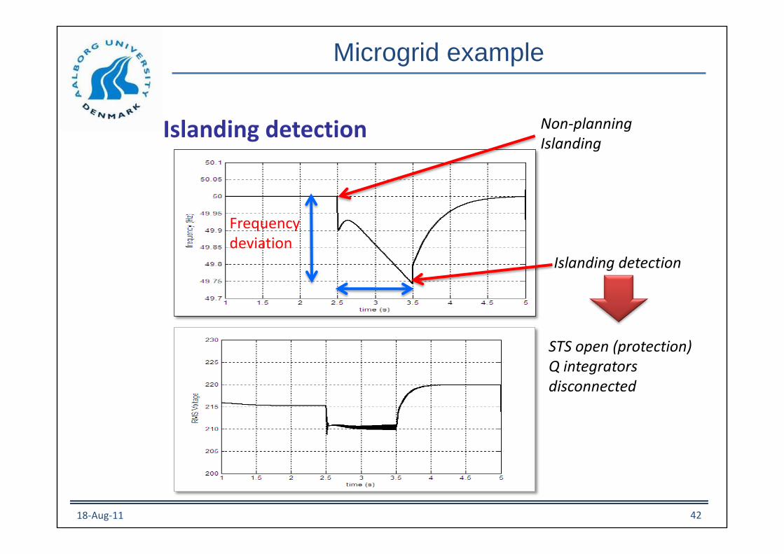
Microgrid example
Islanding detection
Islanding detection
Frequencydeviation
STS open (protection)Q integratorsdisconnected
Non-planningIslanding
18-Aug-11 42

Smart-Grids
Microgrids interconnectionStiff grid
Tertiary SGSecondary SG
Primary SG/Tertiary ClusterSecondary Cluster
Primary ClusterTertiary
Secondary
DG#1
DG#2
Primary
Primary
MG#1
PCC#1
DG#3
DG#4
PrimaryMG#2
PCC#2
Primary
Cluster I Cluster II
18-Aug-11 43

Power Quality in Microgrids
Advanced Active Filtering in a Single Phase High Frequency AC Microgrid - Sudipta Chakraborty
Microgrids
Fuel cell
PV
Battery
SourceBus
PWM PWM
UPQC Controller
UPQC
Non-linearLoad
Linear Load
Load bus
PWM PWM
UPLC Controller
UPLC
Utility
UtilityInvertersand Loads
UtilityConnection
Bus
1cV
V
IntermediateSupply Bus hfV
Loadi
1ci
1ci1cV
hfi
hfVhfi
Loadi
LoadV
CV
ci
cVci
VLi
*P*Q
sV
18-Aug-11 44

Droop control allows P and Q sharing, averaged over the fundamental frequency.
It is not able to guarantee harmonic current sharing!
P
Q
CalculationVref
w
E
PWMInner loops
CL
vo
Inverter
DSP
iovo
A/D
PLL
Pow
er
calc
ula
tion
Power Quality in Microgrids
Harmonic current sharing
18-Aug-11 45
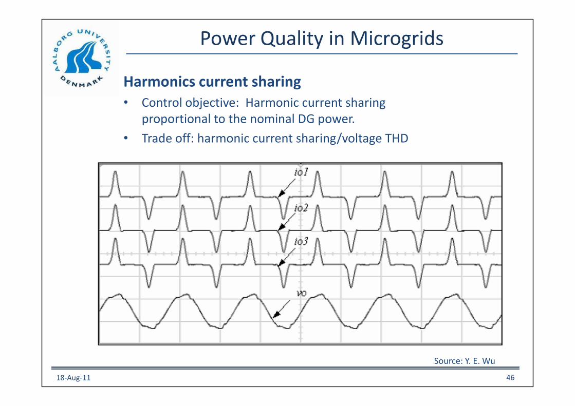
Power Quality in Microgrids
Harmonics current sharing• Control objective: Harmonic current sharing
proportional to the nominal DG power.
• Trade off: harmonic current sharing/voltage THD
Source: Y. E. Wu
18-Aug-11 46
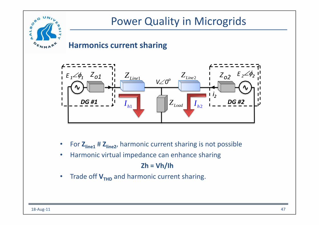
Power Quality in Microgrids
Harmonics current sharing
• For Zline1 # Zline2, harmonic current sharing is not possible
• Harmonic virtual impedance can enhance sharing
Zh = Vh/Ih
• Trade off VTHD and harmonic current sharing.
E 11E 22
V0o
i2DG #1
112
i2
Zo2
DG #2
Zo1
LoadZ
1LineZ 2LineZ
1hI 2hI
18-Aug-11 47

Gp(s)
P&Qcalculation
P1
Q1
Gq(s)
VoltageReferenceE·sin(wt)
w
E
E*
Voltage Loop
vo*
Inverter
Inverter #i
+
_
w*+_
Current Loop + PWM
+_
Zo1
v
i
Virtual output impedance loop
BPFHarmonic current sharing loop
Power Quality in Microgrids
Selective harmonic selection: fundamental and each of the harmonics can have different output impedance.
Droop control
Virtual Output Impedance with harmonic current sharing loop
18-Aug-11 48

Power Quality in Microgrids
Frequency (rad/sec)
Ph
ase (
de
g);
Ma
gn
itu
de (
dB
)
Bode Diagrams
-80
-60
-40
-20
0
20
Virtual output impedance
-100
-50
0
50
100
150
200
1
3 5 7 9 11
103
10410
2
22 2
2)(
ii
ii
sks
sksH
w=
Harmonic current sharing
18-Aug-11 49
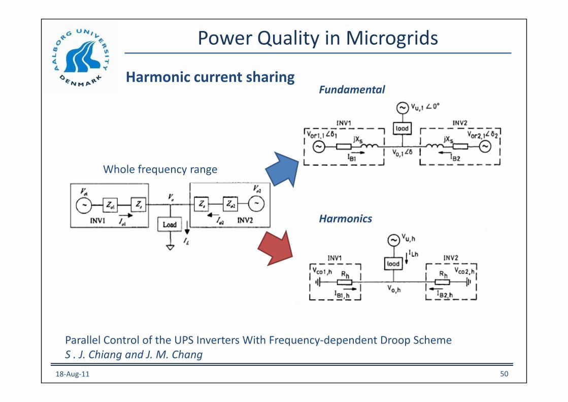
Power Quality in Microgrids
Harmonic current sharing
Parallel Control of the UPS Inverters With Frequency-dependent Droop SchemeS . J. Chiang and J. M. Chang
Whole frequency range
Fundamental
Harmonics
18-Aug-11 50

Power Quality in Microgrids
Droop method with virtual output impedance and selective harmonic
DSP implementation is appropriate for the multi-loop droop framework18-Aug-11 51

(a) Nonlinear load, Y: 2 A/div, X: 5 ms/div; (b) Resistive // nonlineal load, Y: 10 A/div, X: 5 ms/div.
(a) (b)
Power Quality in Microgrids
Droop method for resistive output impedance
18-Aug-11 52

Power Quality in Microgrids
Voltage harmonic reduction by using current harmonics injection
E 1111 Zo1
1LineZ
1hI
PCCV
VgZg
GRIDDG/MG
18-Aug-11 53
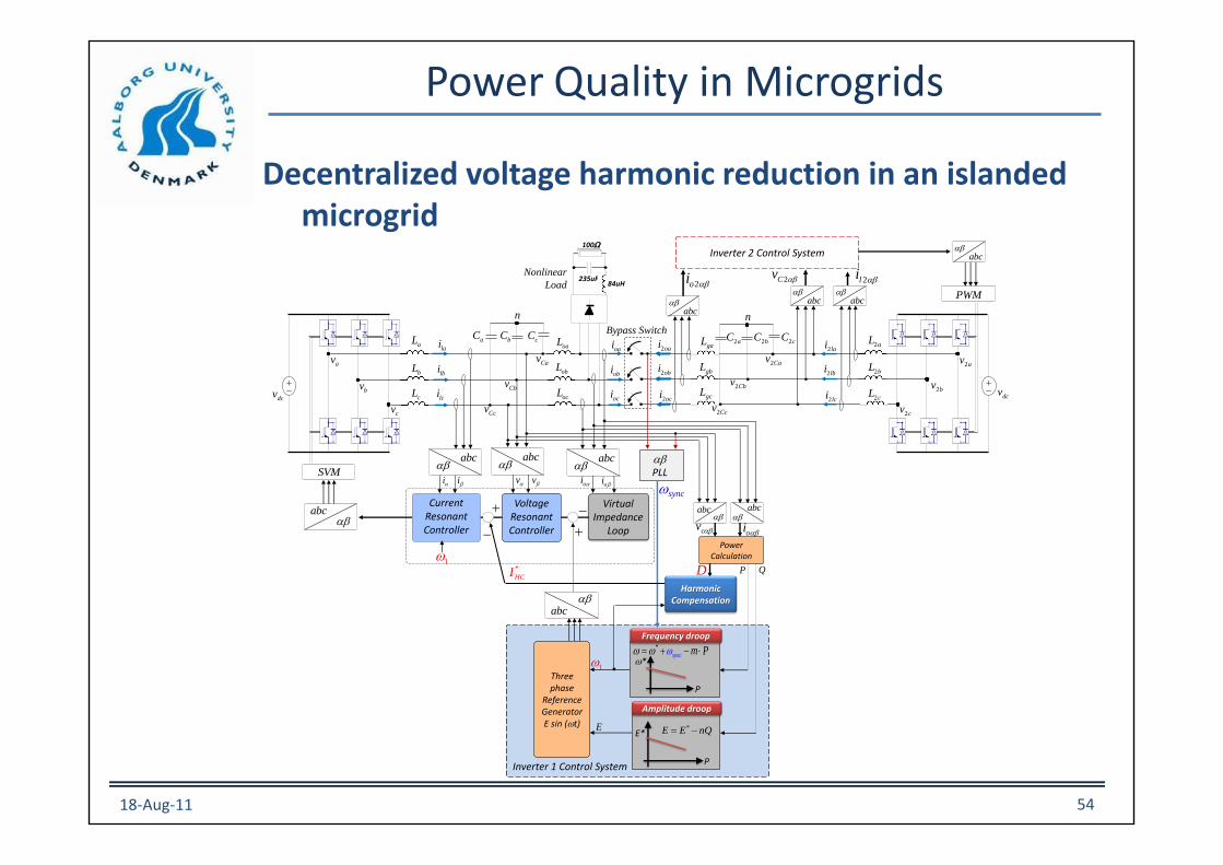
Power Quality in Microgrids
Decentralized voltage harmonic reduction in an islanded microgrid
dcv
av
bv
cv
lbi
lci
aC bC cC
n
Ccv
Cbv
Cav
abc
abc
i i v v oi oi
SVM
Voltage ResonantController
Current Resonant Controller
abc
Virtual Impedance
Loop
abc
lai
Bypass Switch
cL
bL
aLoaL
obL
ocL
gaL
gbL
gcL
*sync m Pww w =
w*
Frequency droop
P
*E E nQ= E*
Amplitude droop
P
abc
abc
abc
obi
oci
oai
P Q
1w
E
1w
Three phase
Reference GeneratorE sin (wt)
syncw
cv oi
dcv
2av
2bv
2cv
2aC 2bC 2cC
n
2Cbv
2Cav
2aL
2bL
2cL
2Ccv
PWM
abcInverter 2 Control System
abc abc
2li
abc
2Cv 2oi
Nonlinear
Load
PLL
2lai
2lbi
2lci
Power Calculation
HarmonicCompensation
2oai
2obi
2oci
D
Inverter 1 Control System
*
HCI
235uF84uH
100W
18-Aug-11 54

Power Quality in Microgrids
Decentralized voltage harmonic reduction in an islanded microgrid
Before Compensation After Compensation
THD% 5th % 7th % THD% 5th % 7th %
Voltage DG1 3.8 2.9 2.0 1.2 0.6 0.5
DG2 2.9 2.1 1.5 1.1 0.5 0.4
Load 5.3 4.2 2.8 3.2 2.3 2.0
Current DG1 58.6 53.7 22.9 87.6 75.2 44.1
DG2 45.8 41.5 18.8 44.5 38.1 22.5
Load 52.2 45.6 20.9 66.1 56.7 33.3
18-Aug-11 55
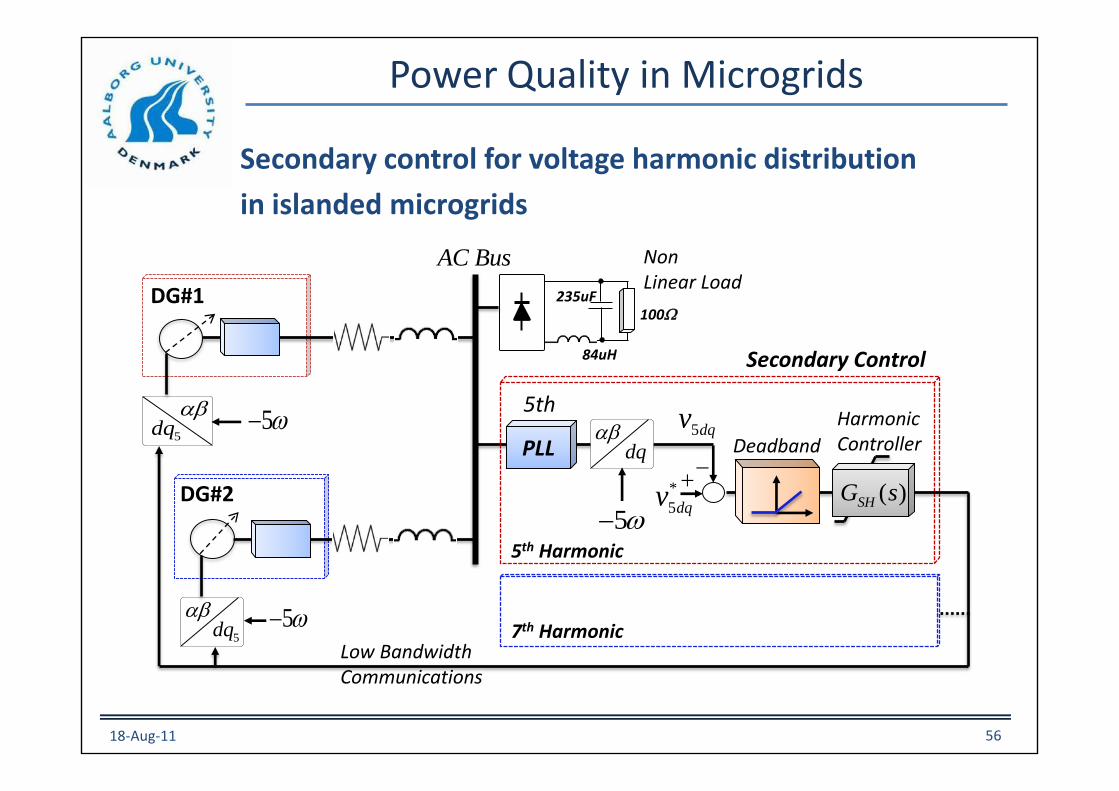
Power Quality in Microgrids
Secondary control for voltage harmonic distribution
in islanded microgrids
AC Bus
DG#1
5dq
DG#2
5dq
PLL dq
5w
*
5dqv
5th
Deadband
5th Harmonic
( )SHG s
Harmonic Controller
Secondary Control
7th HarmonicLow Bandwidth Communications
5w
5w
235uF
84uH
100W
Non Linear Load
5dqv
18-Aug-11 56

Harmonics in Microgrids
18-Aug-11 57
LPF
w
to other
DGs
bv
DG Local Controller
(Primary Level)
dcV
L
L
L
CC
DG Power Stage
Point of Common
Coupling (PCC)
abcoi
abcov
abcLi
C
5dq
HCR
Z
Z
Z
av
abcv
cv
LBCL
Gate Signals
Secondary Controller
1dq
v
5dq
v resE
LBCL
PLL
resw
aoi
boi
coi
aov
bov
cov
aLi
cLi
bLi
7dq
HCR
7dq
v
abcdq
abcdq
7
abcdq
5
LPF
LPF
Secondary control for voltage harmonic compensation in
islanded Microgrids
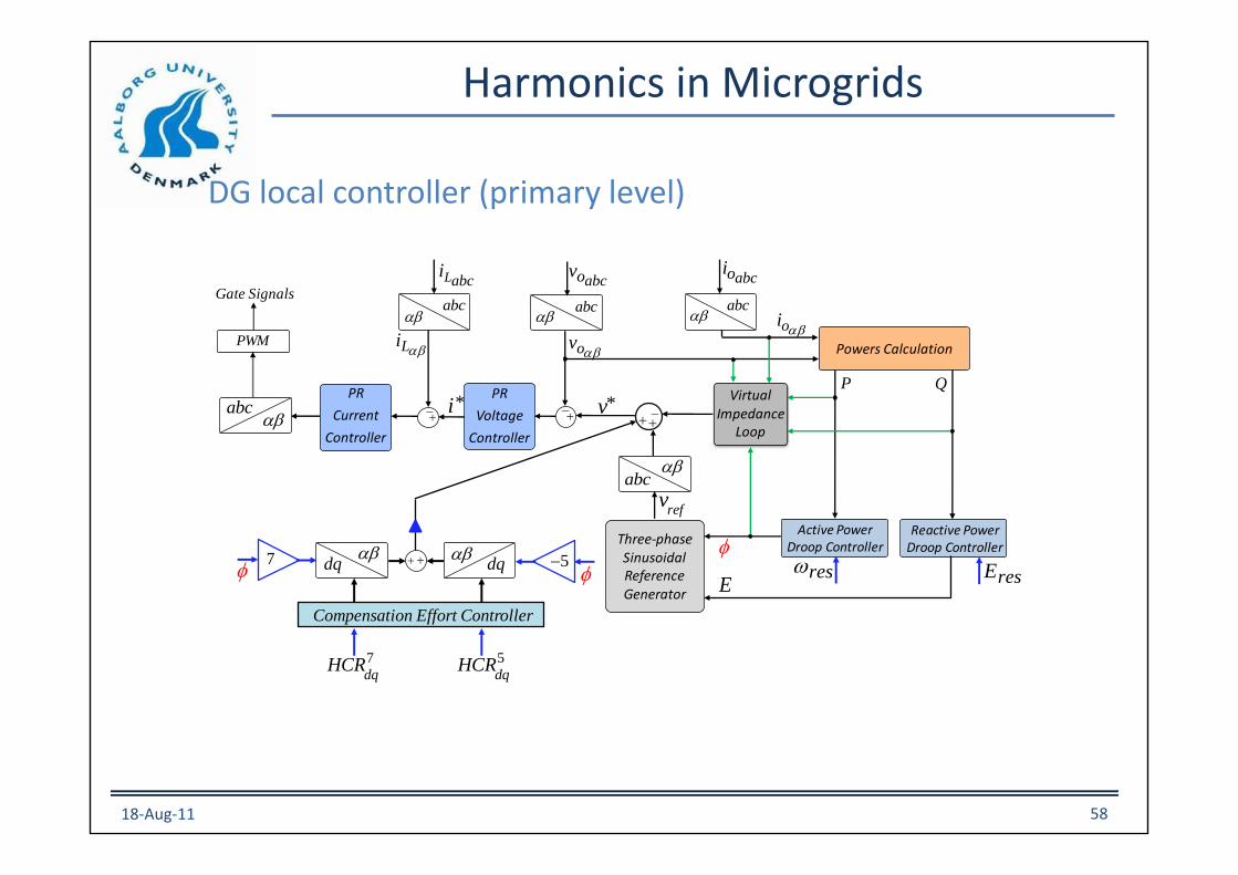
Harmonics in Microgrids
18-Aug-11 58
PR
Current
Controller
PR
Voltage
Controller
Three-phase Sinusoidal Reference Generator
abc
abc
abc
Virtual Impedance
Loop
abc
Powers Calculation
abc
P Q
Active Power Droop Controller
E
PWM
oi
ovLi
abcoiabcovabcLi
*v*i
Reactive Power Droop Controller
Gate Signals
reswresE
7
dqHCR
7
refv
5
dqHCR
5
dq
dq
Compensation Effort Controller
DG local controller (primary level)
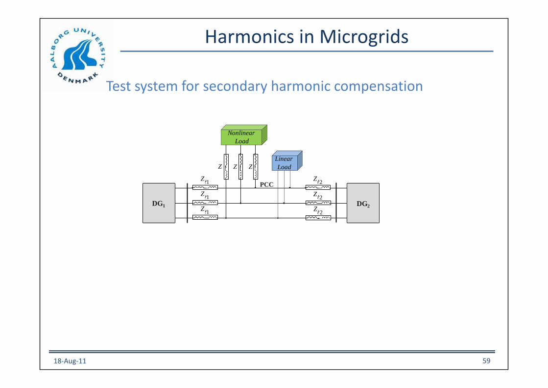
Harmonics in Microgrids
Test system for secondary harmonic compensation
18-Aug-11 59
PCC
DG2
Linear
Load
2Z
DG1
2Z
2Z
1Z
1Z
1Z
Nonlinear
Load
Z Z Z

Harmonics in Microgrids
Secondary control for voltage harmonic compensation
18-Aug-11 60
(a) Before amplitude restoration and harmonic compensation
(b) After amplitude restoration (no harmonic compensation)
(c) After amplitude restoration and harmonic compensation

Unbalance in Microgrids
Voltage unbalance definition
,
,
rms
rms
C
C
vUF
v
=
rmsCv
,
rmsCv
,
Voltage unbalance factor (UF) is considered as the index of unbalance.
UF can be defined as follows:
where and are rms values of negative and positive
sequences of the DG output voltage.
18-Aug-11 61

Unbalance in Microgrids
Unbalance compensation for a grid-connected DG
abc
abc
i i v v oi oi
Voltage P+ResonantController
Current P+ResonantController
abc
Virtual Impedance
Loop
abc
Switch
abc
Three phase
Reference GeneratorE sin ()
RL
Positive and Negative Sequence Calculation
Control System
oi
Cv
Unbalance Compensation
P Q
dcV
oai
obi
oci
oaL
obL
obL
cCbCaC
av
bv
cv
aL
bL
cL
Lai
Lbi
Lci
CavCbv
CcvGRID
gaL
gbL
gcL
gaR
gbR
gcR
*UF
Cv
PI
UF
*
PWM
*E
Cv
ActivePower Controller
ReactivePower Controller
RMSCalculation
Power Calculation
, rmsC
v
, rmsC
v
18-Aug-11 62

Unbalance in Microgrids
Unbalance compensation for a grid-connected DG
DG output Voltage
18-Aug-11 63
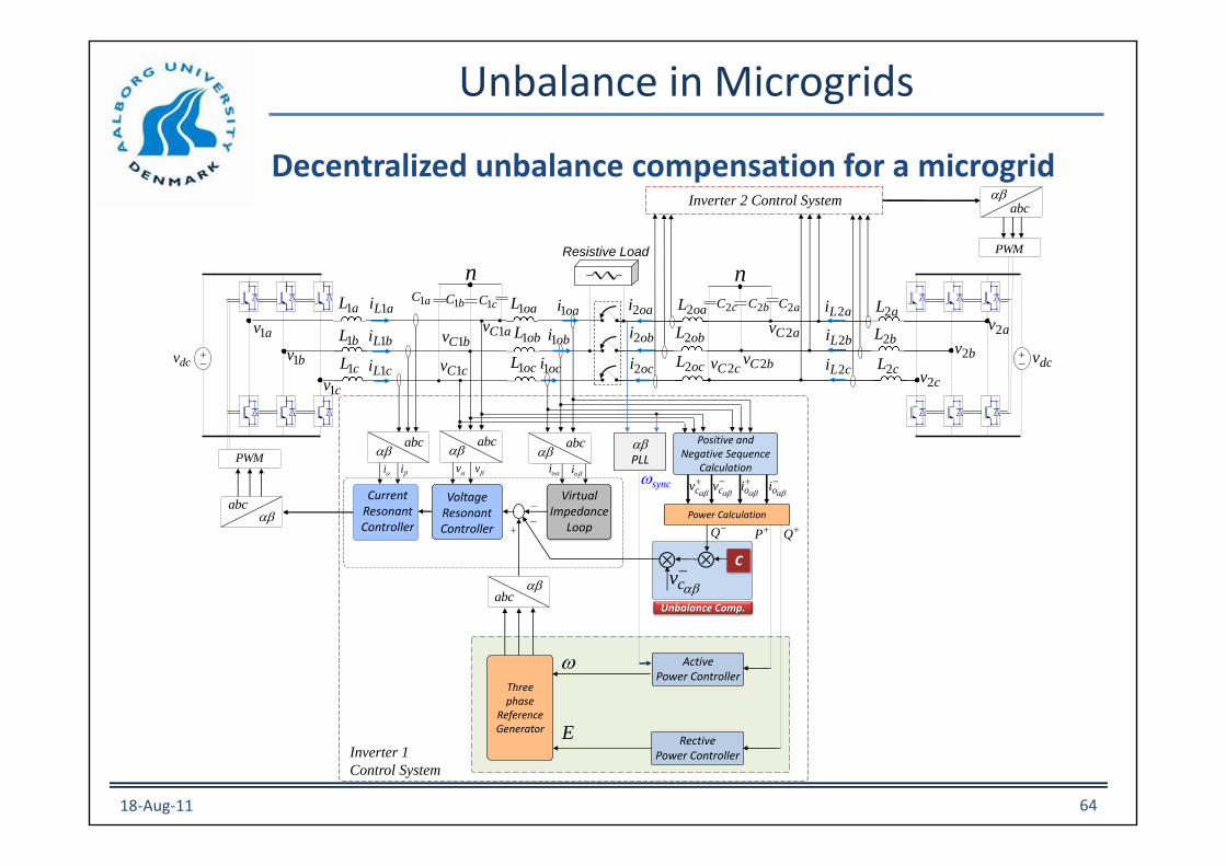
Unbalance in Microgrids
Decentralized unbalance compensation for a microgrid
abc
abc
i i v v oi oi
Voltage ResonantController
Current Resonant Controller
abc
Virtual Impedance
Loop
abc Power Calculation
abc
Three phase
Reference Generator
syncw
nResistive Load
PLL
Positive and Negative Sequence
Calculation
Inverter 1
Control System
Inverter 2 Control Systemabc
cv
oi
oi
cv
C
Q
cv
Unbalance Comp.
P Q
n
av2
bv2
cv2
dcvdcv
aL2
bL2
cL2
aLi 2
bLi 2
cLi 2
aCv 2
bCv 2cCv 2
aC2bC2cC2oaL2
obL2
ocL2
oai2
obi2
oci2
oai1
obi1
oci1
oaL1
obL1
ocL1
cC1bC1aC1
av1
bv1
cv1
aL1
bL1
cL1
aLi 1
bLi 1
cLi 1
aCv 1bCv 1
cCv 1
ActivePower Controller
RectivePower Controller
E
PWM
PWM
w
18-Aug-11 64

Unbalance in Microgrids
Decentralized unbalance compensation for a microgrid
Voltage after and before compensation
Unsymmetrical line
18-Aug-11 65

Unbalance in Microgrids
Secondary control for unbalance compensation in
islanded Microgrids
bv
Three-phase Sinusoidal Reference
Generator
Lai oai
abc
abc
PR
Voltage
Controller
abc
Virtual Impedance
Loop
abc Power Calculation
abc
Positive Sequence Calculation
DGi Local Control System
oi
ov
PQ
dcV
obi
oci
L
L
L
Lbi
Lci
oav
obv
ocv
ActivePower Controller
*E
PWM
*
oiov
Li
CC
DG Power Stage
Point of Common
Coupling (PCC)
abcoiabcovabcLi
refv
refi
C
PR
Current
Controller
iUCR
L
L
L
av
abcv
cv
Positive and Negative Sequence Calculation
v
v
VUF Calculation
VUF
*VUF
ReactivePower Controller
dq
iCSG nCSG
dq
Sec
on
da
ry C
on
tro
ller
Low Bandwidth
Communication LinknUCR
sI
P
kk
18-Aug-11 66
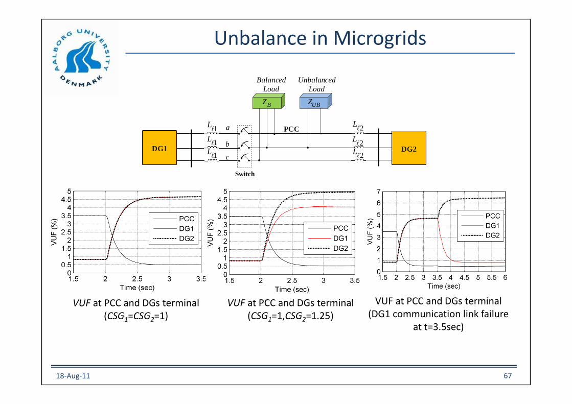
Unbalance in Microgrids
1L
DG2DG1
a
b
c
Unbalanced
Load
Switch
1L
1L
2L
2L
UBZ
Balanced
Load
BZ
PCC
2L
VUF at PCC and DGs terminal (CSG1=1,CSG2=1.25)
VUF at PCC and DGs terminal (CSG1=CSG2=1)
VUF at PCC and DGs terminal (DG1 communication link failure
at t=3.5sec)
18-Aug-11 67

Unbalance in Microgrids
(a)
(b)
(c)
(d)
(e)
(f)
Fig. 8. Three-phase voltage waveforms (a) PCC-before comp. (b) PCC-after comp.
(c) DG1-before comp. (d) DG1-after comp.
(e) DG2-before comp. (f) DG2-after comp.
Three-phase voltage waveforms
PCC
DG1
DG2
BEFORE COMPENSATION AFTER COMPENSATION
18-Aug-11 68

Power Quality in Microgrids
Conclusions
• Voltage harmonics in microgrids can be reduced by injecting current harmonic or adjusting harmonic voltage in the DG terminals
• Secondary control can be used to close the loop of the harmonic voltage compensation in the microgrid
• Tertiary control can be used to reduce the current harmonics injected by the microgrid to the grid
• A ponderated trade off between the secondary and tertiary controls have to be designed
• Unbalances in microgrids can be reduced by injecting a voltage negative sequence in the DG proportional to Q negative sequence
• Secondary control and tertiary control for unbalance compensation can be used for islanding and grid-connected microgrids.
• Reactive power have to be limited and ponderated for harmonics and unbalance compensation.
18-Aug-11 69

Distributed Energy Storage in Microgrids
18-Aug-11 70
PG1
PG2
PG3
PMG
PS1
PS2
Source: “Distribution Voltage Control forDC Microgrid with Fuzzy Control and Gain-Scheduling Control,” H. Kakigano et Al.

Distributed Energy Storage in Microgrids
18-Aug-11 71
SOC1 – SOC2 PS1, PS2
Adaptive droop control:
DC: V=V* - (k/SoC)Io
AC: w=w* - (k/SoC)P
Extended Kalman Fiters are used to obtain the SoC of the batteries.

References
[1] J. M. Guerrero, J. C. Vasquez, J. Matas, M. Castilla, etc, "Control strategy for flexible microgrid based on parallel line-interactive UPS systems," IEEE Trans. Industrial Electronics, Vol. 56, No. 3, pp. 726-736, 2009.
[2] J. M. Guerrero, J. Matas, etc, "Decentralized control for parallel operation of distributed generation inverters using resistive output impedance," IEEE Trans. Industrial Electronics, Vol. 54, No. 2, pp. 994-1004, 2007.
[3] Y. W. Li and C. Kao, "An accurate power control strategy for power-electronics-interfaced distributed generation units operating in a low-voltage multibus microgrid," IEEE Trans. Power Electronics, Vol. 24, No. 12, pp. 2977-2988, 2009.
[4] D. M. Vilathgamuwa, P. C. Loh and Y. W. Li, "Protection of microgrids during utility voltage sags," IEEE Trans. Industrial Electronics, Vol. 53, No. 5, pp. 1427-1436, 2006.
[5] F. Katiraei, M. R. Iravani and P. W. Lehn. "Micro-grid autonomous operation during and subsequent to islanding process," IEEE Trans. Power Delivery, Vol. 20, No. 1, pp. 248-257, 2005.
[6] H. Gaztanaga, I. Etxeberria-Otadui, S. Bacha and D. Roye, "Real-time analysis of the control structure and management functions of a hybrid microgrid system," in Proc. IECON Conf., 2006, pp. 5137-5142.
[7] C. Jin, P. C. Loh, P. Wang, Y. Mi, F. Blaabjerg, "Autonomous operation of hybrid AC-DC microgrids," in Proc. ICSET Conf., 2010.
[8] X. Liu, P, Wang and P. C. Loh, "A hybrid AC/DC microgrid and its coordination control," IEEE Trans. Smart Grid, to be published.
[9] X. Yu, A. M. Khambadkone, H. H. Wang, etc, "Control of parallel-connected power converters for low-voltage microgrid-Part I: A hybrid control architecture," IEEE Trans. Power Electronics, Vol. 25, No. 12, pp. 2962-2970, 2010.
[10] C. T. Lee, C. C. Chuang, C. C. Chu and P. T. Cheng, "Control strategies for distributed energy resources interface converters in the low voltage microgrid," in Proc. ECCE Conf., 2009, pp. 2022-2029.
18-Aug-11 72

Name Josep M. Guerrero (喬瑟輔) Photo
Title Full Professor
Postal
Address
Aalborg University, Institute of Energy
Technology, Pontoppidanstraede 101,
DK-9220 Aalborg East, Denmark
Telephone Tel:
Cell: +34652045551
Email [email protected]
Website www.et.aau.dk
Educational
Background
• 1993 ~ 1997. B.Sc Telecommunications Engineer (Technical University of Catalonia,
Barcelona)
• 1997 ~ 2000. M.Sc Electronic Engineer (Technical University of Catalonia, Barcelona)
• 2000 ~ 2003. PhD Power Electronics (Technical University of Catalonia, Barcelona)
Work
Experience
• Feb 1999 ~Aug 2004 Assistant professor (Technical University of Catalonia, Barcelona)
• Sept 2004 ~Aug 2008 Lecturer professor (Technical University of Catalonia, Barcelona)
• Sept 2008~Present Associate Professor (now part time) (Technical University of Catalonia,
Barcelona)
• July 2011~Present Full Professor (Aalborg University, Spain)
Autobiography
Josep M. Guerrero (S’01–M’04–SM’08) was born in Barcelona, Spain, in 1973. He received the B.S. degree
in telecommunications engineering, the M.S. degree in electronics engineering, and the Ph.D. degree in power
electronics from the Technical University of Catalonia, Barcelona, Spain, in 1997, 2000 and 2003, respectively.
He is part time Associate Professor with the Department of Automatic Control Systems and Computer
Engineering, Technical University of Catalonia, where he currently teaches courses on FPGAs and control of
renewable energy systems. From 2011 he is a Full Professor at the Institute of Energy Technology, Aalborg
Universiy, Denmark, and responsible of the Microgrid research program. He has been a visiting Professor at
Zhejiang University, China, and University of Cergy-Pontoise, France. His research interests include power
electronics converters for distributed generation and distributed energy storage systems, control and
management of microgrids and islanded minigrids, and photovoltaic and wind power plants control. He is an
associate editor of the IEEE Transactions on Industrial Electronics and IEEE Transactions on Power
Electronics. He currently chairs of Renewable Energy Systems Technical Committee of IEEE IES. He is an
elected IEEE IES Adcom member.