Embed Size (px)
Citation preview
Electromagnetismo I
Tarea No. 10
Fecha lımite de entrega 14 de mayo de 2018
Profs. Cecilia Noguez y Omar Vazquez, Ayudante: David Becerril
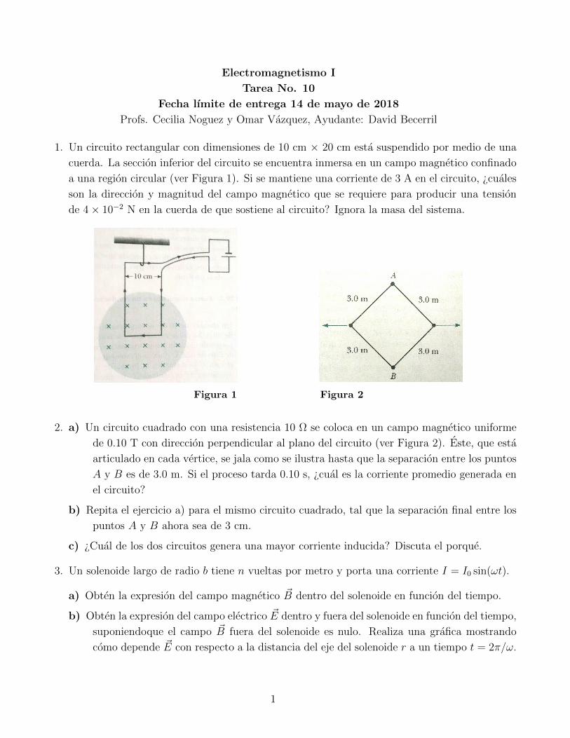
1. Un circuito rectangular con dimensiones de 10 cm × 20 cm esta suspendido por medio de una
cuerda. La seccion inferior del circuito se encuentra inmersa en un campo magnetico confinado
a una region circular (ver Figura 1). Si se mantiene una corriente de 3 A en el circuito, ¿cuales
son la direccion y magnitud del campo magnetico que se requiere para producir una tension
de 4× 10⁻² N en la cuerda de que sostiene al circuito? Ignora la masa del sistema.
Electromagnetismo I (2014-2)
Tarea No. 7. Fecha de Entrega: Jueves 10 de abril.
Prof. Dra. Cecilia Noguez y M. en C. Francisco Hidalgo
Ayudante: David Becerril
[email protected]; Cub. 61 o 136, Edif. Principal IFUNAM
1. Una bola metalica que tiene una carga neta Q se lanza horizontalmente por una ventana a una velocidad v.
La ventana se encuentra a una altura h sobre el suelo. Un campo magnetico horizontal uniforme de magnitud
B es perpendicular al plano de la trayectoria de la bola.
a) Encuentre la fuerza magnetica que actua sobre la bola justo antes de que esta golpee el suelo.
b) Resuelva el problema anterior asumiendo que Q = 5µC, v = 20 m/s, h = 20 m y B = 0.010 T. Realiza
claramente el analisis de unidades.
2. a) Un circuito rectangular con dimensiones de 10 cm 20 cm esta suspendido por medio de una cuerda, y
la seccion inferior del lazo se encuentra inmersa en un campo magnetico confinado a una region circular
(ver figura 1). Si se mantiene una corriente de 3 A en el circuito en la direccion mostrada, ¿cuales son
la direccion y magnitud del campo magnetico requerido para producir una tension de 4 102 N en la
cuerda de soporte? Ignora la masa del sistema.
Figura 1:
b) Una vez calculado el campo anterior, ahora supon que todo el circuito se encuentra inmerso en el campo
magnetico. Calcula la fuerza total que experimenta el circuito.
3. Considera el caso de un alambre conductor largo y recto por el que circula una corriente electrica I. El campo
magnetico B generado, ası como su correspondiente potencial vectorial A estan dados como:
B =µ0I
2r, A = z
µ0I
2ln r.
Reescribe las ecuaciones anteriores en terminos de coordenadas rectangulares y verifica que r A = B.
4. Tres alambres conductores rectos se localizan de modo que son perpendiculares a la hoja (ver figura 2). Un
alambre porta un corriente 2I hacia adentro de la hoja, mientras que los otros dos portan una corriente I
hacia afuera de la hoja.
1
distancia r, como se muestra en la figura 2. Demuestra que la fem inducida en la barra es
fem =µ0I
2v ln
1 +
l
r
.
Figura 2:
4. a) El lazo cuadrado de 10 que inicialmente se muestra en la figura 3 se coloca en un campo magnetico
uniforme de 0.10 T con direccion perpendicular al plano del lazo. Este, que esta articulado en cada
vertice, se jala como se ilustra hasta que la separacion entre los puntos A y B es de 3.0 m. Si el proceso
tarda 0.10 s, ¿cual es la corriente promedio generada en el lazo?
b) Repita el problema anterior para el mismo lazo cuadrado, tal que la separacion final entre los puntos A
y B ahora sea de 3 cm.
c) ¿Cual de los dos circuitos genera una mayor corriente inducida? Discuta.
Figura 3:
5. Un solenoide largo de radio b tiene n vueltas por metro de longitud y porta una corriente i = i0 sin!t.
2
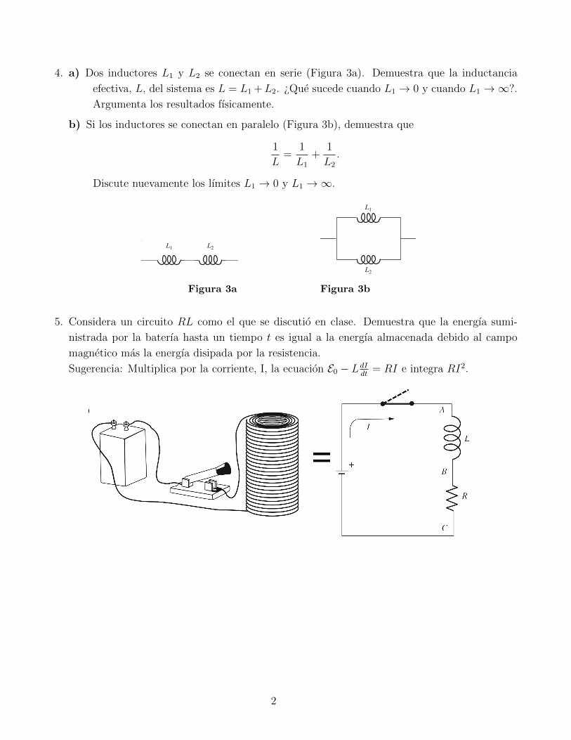
Figura 1 Figura 2
2. a) Un circuito cuadrado con una resistencia 10 Ω se coloca en un campo magnetico uniforme
de 0.10 T con direccion perpendicular al plano del circuito (ver Figura 2). Este, que esta
articulado en cada vertice, se jala como se ilustra hasta que la separacion entre los puntos
A y B es de 3.0 m. Si el proceso tarda 0.10 s, ¿cual es la corriente promedio generada en
el circuito?
b) Repita el ejercicio a) para el mismo circuito cuadrado, tal que la separacion final entre los
puntos A y B ahora sea de 3 cm.
c) ¿Cual de los dos circuitos genera una mayor corriente inducida? Discuta el porque.
3. Un solenoide largo de radio b tiene n vueltas por metro y porta una corriente I = I0 sin(ωt).
a) Obten la expresion del campo magnetico ~B dentro del solenoide en funcion del tiempo.
b) Obten la expresion del campo electrico ~E dentro y fuera del solenoide en funcion del tiempo,
suponiendoque el campo ~B fuera del solenoide es nulo. Realiza una grafica mostrando
como depende ~E con respecto a la distancia del eje del solenoide r a un tiempo t = 2π/ω.
1
4. a) Dos inductores L1 y L2 se conectan en serie (Figura 3a). Demuestra que la inductancia
efectiva, L, del sistema es L = L1 +L2. ¿Que sucede cuando L1 → 0 y cuando L1 →∞?.
Argumenta los resultados fısicamente.
b) Si los inductores se conectan en paralelo (Figura 3b), demuestra que
1
L=
1
L1
+1
L2
.
Discute nuevamente los lımites L1 → 0 y L1 →∞.
378 Electromagnetic induction
Compute the total work done by external agencies, for each of thetwo programs. Then complete the argument. See Crawford (1992)for further discussion.
7.11 L for a solenoid *Find the self-inductance of a long solenoid with radius r, length ℓ,and N turns.
7.12 Doubling a solenoid *(a) Two identical solenoids are connected end-to-end to make
a solenoid of twice the length. By what factor is the self-inductance increased? The answer quickly follows from theformula for a solenoid’s L, but you should also explain inwords why the factor is what it is.
(b) Same question, but now with the two solenoids placed righton top of one another. (Imagine that one solenoid is slightlywider and surrounds the other.) They are connected so that thecurrent flows in the same direction in each.
7.13 Adding inductors *(a) Two inductors, L1 and L2, are connected in series, as shown in
Fig. 7.32(a). Show that the effective inductance L of the systemis given by
L = L1 + L2. (7.84)
Check the L1 → 0 and L1 → ∞ limits.(b) If the inductors are instead connected in parallel, as shown in
Fig. 7.32(b), show that the effective inductance is given by
1L
= 1L1
+ 1L2
. (7.85 )
Again check the L1 → 0 and L1 → ∞ limits.
(a)
(b)
L1
L1
L2
L2
Figure 7.32.
7.14 Current in an RL circuit **Show that the expression for the current in an RL circuit given inEq. (7.69) follows from Eq. (7.65 ).
7.15 Energy in an RL circuit *Consider the RL circuit discussed in Section 7.9. Show that theenergy delivered by the battery up to an arbitrary time t equalsthe energy stored in the magnetic field plus the energy dissipatedin the resistor. To do this, multiply Eq. (7.65 ) by I to obtain I2R =I(E0 −L dI/dt), and then integrate this equation.
7.16 Energy in a superconducting solenoid *A superconducting solenoid designed for whole-body imaging bynuclear magnetic resonance is 0.9 meters in diameter and 2.2 meterslong. The field at its center is 3 tesla. Estimate roughly the energystored in the field of this coil.
Figura 3a Figura 3b
5. Considera un circuito RL como el que se discutio en clase. Demuestra que la energıa sumi-
nistrada por la baterıa hasta un tiempo t es igual a la energıa almacenada debido al campo
magnetico mas la energıa disipada por la resistencia.
Sugerencia: Multiplica por la corriente, I, la ecuacion E0 − LdIdt
= RI e integra RI2.
2


![113894311 Biblia Etica y Apocaliptica Noguez Armando[1]](https://img.pdfslide.tips/doc/110x75/5572117c497959fc0b8f09d4/113894311-biblia-etica-y-apocaliptica-noguez-armando1.jpg)