Embed Size (px)
DESCRIPTION
ESOA300-FBF01 IOM
Citation preview
DELTA POWER SYSTEM
User manual

ESOA300-FBF01 IOM 2011. 11. 09
ESOA300-FBF01 Outdoor Power System
User Manual
ESOA300-FBF01 IOM
Page: 2 of 43
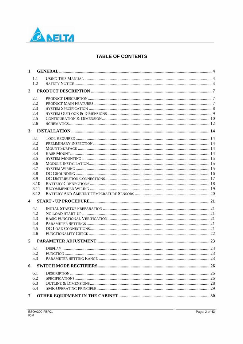
TABLE OF CONTENTS
1 GENERAL ........................................................................................................................................... 4 1.1 USING THIS MANUAL .................................................................................................................... 4 1.2 SAFETY NOTICE............................................................................................................................. 4
2 PRODUCT DESCRIPTION .............................................................................................................. 7 2.1 PRODUCT DESCRIPTION................................................................................................................. 7 2.2 PRODUCT MAIN FEATURES ........................................................................................................... 7 2.3 SYSTEM SPECIFICATION ................................................................................................................ 8 2.4 SYSTEM OUTLOOK & DIMENSIONS ............................................................................................... 9 2.5 CONFIGURATION & DIMENSION.................................................................................................. 10 2.6 SCHEMATICS................................................................................................................................ 12
3 INSTALLATION .............................................................................................................................. 14 3.1 TOOL REQUIRED .......................................................................................................................... 14 3.2 PRELIMINARY INSPECTION .......................................................................................................... 14 3.3 MOUNT SURFACE ........................................................................................................................ 14 3.4 BASE MOUNT............................................................................................................................... 14 3.5 SYSTEM MOUNTING .................................................................................................................... 15 3.6 MODULE INSTALLATION.............................................................................................................. 15 3.7 SYSTEM WIRING .......................................................................................................................... 15 3.8 DC GROUNDING .......................................................................................................................... 16 3.9 DC DISTRIBUTION CONNECTIONS............................................................................................... 17 3.10 BATTERY CONNECTIONS ............................................................................................................. 18 3.11 RECOMMENDED WIRING ............................................................................................................. 19 3.12 BATTERY AND AMBIENT TEMPERATURE SENSORS .................................................................... 20
4 START - UP PROCEDURE............................................................................................................. 21 4.1 INITIAL STARTUP PREPARATION ................................................................................................. 21 4.2 NO LOAD START-UP .................................................................................................................... 21 4.3 BASIC FUNCTIONAL VERIFICATION............................................................................................. 21 4.4 PARAMETER SETTINGS ................................................................................................................ 21 4.5 DC LOAD CONNECTIONS............................................................................................................. 21 4.6 FUNCTIONALITY CHECK.............................................................................................................. 22
5 PARAMETER ADJUSTMENT....................................................................................................... 23 5.1 DISPLAY....................................................................................................................................... 23 5.2 FUNCTION .................................................................................................................................... 23 5.3 PARAMETER SETTING RANGE ..................................................................................................... 23
6 SWITCH MODE RECTIFIERS...................................................................................................... 26 6.1 DESCRIPTION ............................................................................................................................... 26 6.2 SPECIFICATIONS........................................................................................................................... 26 6.3 OUTLINE & DIMENSIONS............................................................................................................. 28 6.4 SMR OPERATING PRINCIPLE....................................................................................................... 29
7 OTHER EQUIPMENT IN THE CABINET................................................................................... 30

ESOA300-FBF01 IOM
Page: 3 of 43
7.1 HEAT EXCHANGER ...................................................................................................................... 30 7.2 HUMIDITY SENSOR ...................................................................................................................... 32 7.3 FAN TRAY.................................................................................................................................... 32 7.4 DOOR ALARM .............................................................................................................................. 36
8 ALARMS AND TROUBLE SHOOTING....................................................................................... 37 8.1 AC FAIL/AC HIGH VOLTAGE / AC LOW VOLTAGE ALARM DESCRIPTION................................ 37 8.2 DC OUTPUT VOLTAGE HIGH/LOW (HV/LV) .............................................................................. 38 8.3 DC CIRCUIT BREAKER TRIPPED ALARM..................................................................................... 38 8.4 OVER-TEMPERATURE ALARM..................................................................................................... 39 8.5 RECTIFIER FAIL ALARM .............................................................................................................. 39
9 MAINTENANCE .............................................................................................................................. 40 9.1 CLEANING AND MAINTENANCE................................................................................................... 40 9.2 REMOVING AND REPLACING A RECTIFIER MODULE ................................................................... 40 9.3 AIR FILTER MAINTENANCE ......................................................................................................... 41 9.4 REPLACING THE FILTER............................................................................................................... 41 9.5 MAINTENANCE NOTICE ............................................................................................................... 42

ESOA300-FBF01 IOM
Page: 4 of 43
1 GENERAL
1.1 Using This Manual This manual contains specifications and instructions to properly install, commissioning and maintain the outdoor power system. Component specifications, checklist and drawings are contained in this manual. Included in this manual is the operation and maintenance of the New Smart CSU (NCSU), Switch Mode Rectifier (SMR), Power Distribution Unit (PDU), Heat Exchanger and Low Voltage Battery Disconnect (LVBD) and Low Voltage Load Disconnect (LVLD), system status and alarms, troubleshooting and system maintenance. Step by step procedures required for installation and turn-up are detailed. All equipment parameter settings, adjustments and confirmation as well as system monitoring, operations and maintenance procedures are included. Warnings are printed in bold lettering and alert the installation or maintenance craftsperson of a potential hazard to either or the craftsperson if the warning advisement is not followed.
1.2 Safety Notice Products are not liable for any hazards incurred by not following proper safety procedures. Installation, Operation and maintenance personnel should always follow these safety rules:
1. The equipment is designed for installation and use in areas designated as "Restricted Access Location" only. Where the rack will be secured to a concrete or other non-combustible floor.
2. Per UL and the NEC an insulated grounding conductor, identical in size and insulation characteristics to the supply conductors, is to be installed as part of the branch circuit that supplies the unit or system. The grounding conductor should be green, with or without yellow stripes.
3. The grounded conductor described up above is to be grounded to the earth at the service equipment or if supplied by a separate derived system, at the supply transformer or motor-generator set.
4. The AC receptacles in the vicinity of the power system are all to be of a grounding type and the grounding conductors serving all receptacles are to be connected to earth ground at the service equipment.
5. Before the system is operational, the AC input frequency and voltage must be verified making sure the AC breaker rating and type are adequate and other environmental conditions as noted in the specifications are met.
6. A readily accessible disconnect device shall be incorporated in the building installation wiring.
7. Protective systems or devices in PRIMARY CIRCUITS shall be in such a number and located so as to detect and to interrupt the over-current flowing in any possible fault current path (for example, line-to-line, line-to-neutral, line to protective earth conductor or line to PROTECTIVE BONDING CONDUCTOR).

ESOA300-FBF01 IOM
Page: 5 of 43
8. In a supply using more than one line conductor to a load, if a protective device interrupts the neutral conductor, it shall also interrupt all other supply conductors. Single pole protective devices, therefore, shall not be used in such cases.
9. The system has passed stringent system testing prior to shipment. To avoid electrical shock, the system requires a single ground point permanently connected to earth ground.
10. Recommended outside ambient is maximum +40℃.
11. To avoid electrical hazards, the covers must not be removed on the system or any component.
12. DC output & battery breakers must be replaced with approved replacement circuit breakers meeting the original design specification.
13. All AC connections must be made per the latest issue of the National Electrical Code and must conform to all local codes.
14. The wiring method to accommodate different power systems should comply with National Electrical Code and Local Code.
15. Always keep door closed at any time if no maintenance required to prevent organism intruding.
16. Make sure door is latched and locked properly before leaving to avoid vandalism or water/dust ingress.
17. Do not open door in rainy or bad climate.
18. Only well-trained people can access the system.
19. Use specified or approved component for replacement such as air filter, fan, etc.
20. Follow instruction to perform needed maintenance
21. Do not roll the cabinets on their sides.
22. Do not store anything on top of the cabinet.
23. Ensure that utility power is disabled before beginning installation or removal.
24. Ensure no liquids or wet clothes contact internal components.
25. Do not smoke or introduce sparks in the vicinity of a battery.
26. Follow the battery manufacturer’s approved transportation and storage instructions.
27. Each individual battery should have at least 0.25 inches of space between it and surrounding surfaces , or per the battery manufacturer’s specification to allow for convective cooling.
28. Follow battery manufacturer’s approved instructions to set all battery related parameters accordingly.
29. The thermal result shows the cabinet can provide the required performance for the following equipment conditions:
A. 92% SMR @ 150A load (8.1kw)
ESOA300-FBF01 IOM
Page: 6 of 43
TM < 55℃
RBS6601 x 2 < 55℃
PSU < 60℃ (no current limited)
Battery < 43℃
B. 96% SMR @ 200A load (10.8kw)
TM < 50℃
RBS6601 x 2 < 50℃
PSU < 55℃ (no current limited)
Battery < 43℃
ESOA300-FBF01 IOM
Page: 7 of 43
2 PRODUCT DESCRIPTION
2.1 Product Description The Power System consists of modular ESR series rectifiers, a New Smart CSU (NCSU), a Power Distribution Unit (PDU), a Heat Exchanger, a Low Voltage Battery Disconnect (LVBD) and a Low Voltage Load Disconnect (LVLD).
Up to 4 rectifiers can be equipped in the shelf, which can mount a NCSU. The system requires a nominal input of 380VAC and provide an output of –54 VDC to power the load and also maintain fully charged batteries.
The system is control by the New Smart CSU (NCSU). System monitor status alarms of rectifiers and control output voltage, fan tray start point by NCSU. All system parameters are set by NCSU too. The USB interface of NCSU is the Remote Monitoring System (RMS) software to remote and control system by PC.
2.2 Product Main Features • - 54Vdc / 200A Max. (Rectifiers 1-4, 19” shelf).
• The outdoor system equip with New Smart CSU (NCSU)
• User Friendly LCD Interface (NCSU, 128*64 dots display)
• Hot Swappable 2700 Watts rectifiers, wide range PFC input (90~275Vac good for unstable utility environment)
• Light Weight Plug-in Modules for Simple Installation and Maintenance
• High Power Density Saves Valuable Floor space
• All rectifier modules are front accessible
• Active Power Factor Correction (> .99 PF)
• High Efficiency
• Temperature Compensation Float Voltage Control for VRLA Batteries
• Front Access for Simplified Operation and Maintenance
• Intelligent remote shelf monitoring and control (Optional RMS software function and Modem function, Via USB
• Network Maintenance
• Battery temperature compensation voltage control
• Battery and Load breakers
• Equalize charge timer
• Fan tray and Heat exchanger for temperature control
• Low voltage disconnect: LVBD & LVLD
• Humidity Detector
• Door open detector

ESOA300-FBF01 IOM
Page: 8 of 43
2.3 System Specification
Item Specification/Function
AC Input Voltage 3ψ, 3W+N +PE , ~ 380/220V or single phase 220V
AC Input Frequency 50/60 Hz ±5%
System Capacity -54V / 200A Max (1 ~ 4 rectifiers)
Rectifier ESR-48/56A B or ESR-48/40A A or ESR-48/56B A
Control & Supervisor Unit LCD Display: 128 * 64 characters
Battery Breaker C120 * 4 positions
Output Breaker High priority * 8 positions
Low priority * 11 positions
LVDS 1. LVBD (Low Voltage Battery Disconnect) * 1 2. LVLD (Low Voltage Load Disconnect) * 1
Remote Monitoring and Control By RMS software (Use USB Interface)
Operating Temperature 32℉~+104℉ (0℃~+40℃)
Storage Temperature -40℉~+167℉ (-40℃~+75℃)
Humidity 0~95% Relative Humidity, Non-Condensing
Altitude
< 3000m above mean sea level 0 - 2000 m: Full of the nominal output power rating at maximum temperature. 2000 m - 3000 m: 1% power derating per 100m. At 3000m altitude, the output power can be 90% of the nominal power rating at maximum temperature.
Acoustic <65 dB(A) at the distance of 1m in front of rectifier with 1.5m height,
25 ℃ ambient,
Recommended clearance for service
Top Clearance--- 100mm minimum. Front Clearance--- 780mm minimum.
Controller Delta New Smart CSU

ESOA300-FBF01 IOM
Page: 9 of 43
2.4 System Outlook & Dimensions
Item Specification/Function
Dimension (WxDxH) 750mm x 750mm x 1990mm
ESOA300-FBF01 IOM
Page: 10 of 43
2.5 Configuration & Dimension
2.5.1 Shelf Configuration
DPR2000/2700 Series DPR2000/2900 HE SeriesRectifiers x6 max.
Delta Controller CSU 501+
DC 0V Bus With
cable clamps
LVBD for Batt side
LVLD for Low
Priority LoadDC 48V Bus
AC Input Terminal
High Priotiry Load
C60 x 8 max. Low Priotiry Load
C120 (two poles) x 1 & C60 x 9 max.
DC SPD
(Optional)
Web/SNMP
(Optional)
min-USB Port
ESOA300-FBF01 IOM
Page: 11 of 43
2.5.2 System Configuration

ESOA300-FBF01 IOM
Page: 12 of 43
2.6 Schematics
2.6.1 Shelf Schematics
ESOA300-FBF01 IOM
Page: 13 of 43
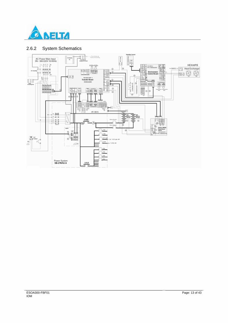
2.6.2 System Schematics
ESOA300-FBF01 IOM
Page: 14 of 43
3 INSTALLATION
3.1 Tool Required The following tools are recommended for the system installation: • Phillips No. 3 screw driver • Tweaker - Slotted screw driver blade size .09”× .02” • Torx T25 screw driver • Thomas & Betts crimping tool TBM8-750-1 • Insulated side cutters • Metric Socket Wrenches with Extensions • Hydraulic lifter
3.2 Preliminary Inspection Prior to removing the system from the crate, note any damage to the crate. Remove the system cabinet from the crate and inspect the shelf for any dents or damage. If any damage is noted, contact the carrier immediately.
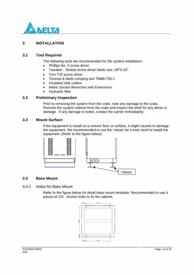
3.3 Mount Surface If the equipment is install on a uneven floor or surface, it might caused to damage the equipment. We recommended to use the I-beam for a even level to install the equipment. (Refer to the figure below)
3.4 Base Mount
3.4.1 Holes for Base Mount Refer to the figure below for detail base mount template. Recommended to use 4 pieces of 12ψ Anchor bolts to fix the cabinet.
I Beam
ESOA300-FBF01 IOM
Page: 15 of 43
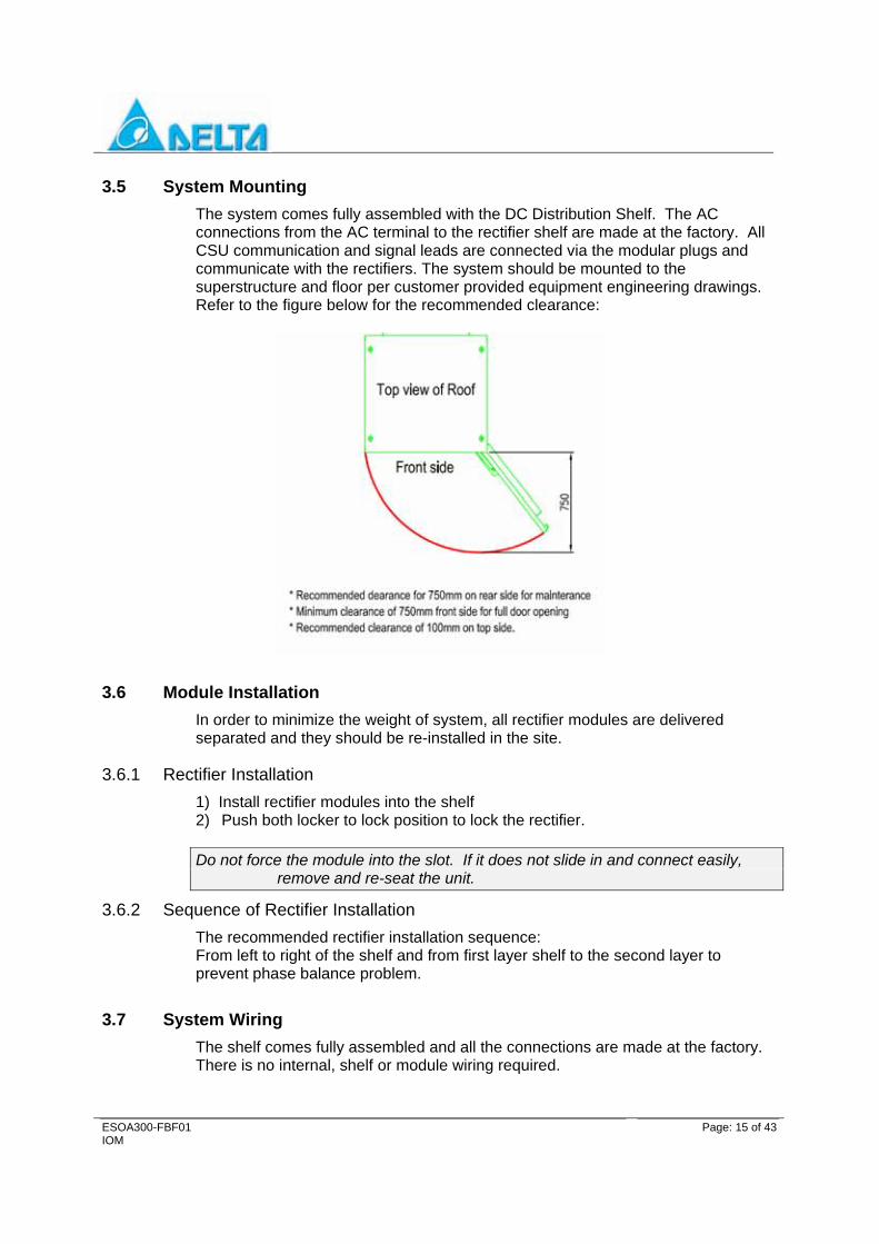
3.5 System Mounting The system comes fully assembled with the DC Distribution Shelf. The AC connections from the AC terminal to the rectifier shelf are made at the factory. All CSU communication and signal leads are connected via the modular plugs and communicate with the rectifiers. The system should be mounted to the superstructure and floor per customer provided equipment engineering drawings. Refer to the figure below for the recommended clearance:
3.6 Module Installation In order to minimize the weight of system, all rectifier modules are delivered separated and they should be re-installed in the site.
3.6.1 Rectifier Installation 1) Install rectifier modules into the shelf 2) Push both locker to lock position to lock the rectifier. Do not force the module into the slot. If it does not slide in and connect easily,
remove and re-seat the unit.
3.6.2 Sequence of Rectifier Installation The recommended rectifier installation sequence: From left to right of the shelf and from first layer shelf to the second layer to prevent phase balance problem.
3.7 System Wiring The shelf comes fully assembled and all the connections are made at the factory. There is no internal, shelf or module wiring required.

ESOA300-FBF01 IOM
Page: 16 of 43
All wiring to the breaker are use lead with striped ends. Ensure to tight the screw and keep the wires are all into the breaker terminal, no any wires or threads are remain outside of the breaker to avoid short-circuit. Refer to the figure below.
3.8 DC Grounding The DC ground must be connected to a permanent earth ground connection.
Do not connect this terminal to AC power system neutral.
3.8.1 AC Wire Connection
3.8.1.1 Single phase 220V Connection
OK NG
Remain wires or threads
ESOA300-FBF01 IOM
Page: 17 of 43
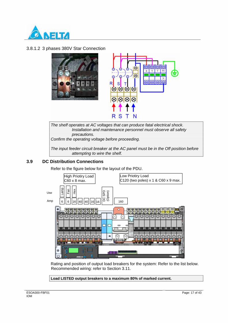
3.8.1.2 3 phases 380V Star Connection
The shelf operates at AC voltages that can produce fatal electrical shock. Installation and maintenance personnel must observe all safety precautions.
Confirm the operating voltage before proceeding. The input feeder circuit breaker at the AC panel must be in the Off position before
attempting to wire the shelf.
3.9 DC Distribution Connections Refer to the figure below for the layout of the PDU.
6 6 16 40 40 16 16 160
Lam
p
Fan
Hex
High Priotiry Load C60 x 8 max.
Low Priotiry Load C120 (two poles) x 1 & C60 x 9 max.
DC
SP
D
(Opt
ion)
Amp
Use
Rating and position of output load breakers for the system: Refer to the list below. Recommended wiring: refer to Section 3.11.
Load LISTED output breakers to a maximum 80% of marked current.
ESOA300-FBF01 IOM
Page: 18 of 43
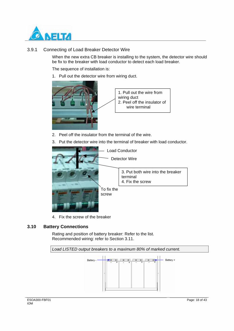
3.9.1 Connecting of Load Breaker Detector Wire When the new extra CB breaker is installing to the system, the detector wire should be fix to the breaker with load conductor to detect each load breaker.
The sequence of installation is:
1. Pull out the detector wire from wiring duct.
2. Peel off the insulator from the terminal of the wire.
3. Put the detector wire into the terminal of breaker with load conductor.
4. Fix the screw of the breaker
3.10 Battery Connections Rating and position of battery breaker: Refer to the list. Recommended wiring: refer to Section 3.11.
Load LISTED output breakers to a maximum 80% of marked current.
1. Pull out the wire from wiring duct 2. Peel off the insulator of
wire terminal
Load Conductor
Detector Wire
3. Put both wire into the breaker terminal 4. Fix the screw
To fix the screw

ESOA300-FBF01 IOM
Page: 19 of 43
3.10.1 Battery Cable Use a copper washer when connecting the battery cable on the battery with the terminal size of M6.
3.11 Recommended Wiring The recommended wire size (AWG#) for each breaker, refer to the 60 °C column for copper wire and with at least 90° C insulation.
The comparison list for wiring size of AWG and mm

ESOA300-FBF01 IOM
Page: 20 of 43
3.12 Battery And Ambient Temperature Sensors One battery sensor cable is provided with each system. The cable is labeled TB terminate on connector TB and on the temperature sensor. Place and fix the temperature sensor on the center of the battery connection bus bar to detecting the battery temperature.
The Ambient Temperature Sensor is labeled TA2 and can be placed anywhere in the left cabinet of clear of the rectifier fan flow to sense the temperature of the left cabinet. (The TA Sensor had already fix on the appropriate location of the cabinet by factory, no required to install by customer of this item). The other Ambient Temperature Sensor is labeled TA1 and it should be placed anywhere of the right cabinet to sense the temperature of the right cabinet. This Ambient Temperature Sensor TA1 is connected to the environment board.

ESOA300-FBF01 IOM
Page: 21 of 43
4 START - UP PROCEDURE
4.1 Initial Startup Preparation Verify all connections prior to starting this section.
Ensure the input AC circuit breaker located at the AC service panel is switched to the “Off” position.
Confirm the operating voltage before proceeding.
Ensure the frame ground is properly connected to a permanent earth ground connection.
Ensure all the Load DC Circuit breakers located in the DC Distribution Cabinet are switched to the “Off” position.
4.2 No Load Start-up The shelf can be turned up without a load. The start-up procedure is as follows:
1. Switch all DC circuit breakers (load) to the “Off” position.
2. Make sure battery is not connected to the system Battery Bus.
3. Check the CSU for alarm status.
4.3 Basic Functional Verification After shelf start-up, basic functional verification should proceed.
Check the monitor of CSU display.
4.4 Parameter Settings Most parameters are pre-set at the factory and are listed on the shelf Test Report included with each shelf.
In all battery related parameters refer to the battery manufacturer specifications.
4.5 DC Load Connections
Basic Functional Testing should be completed prior to the load being applied.
Switch all DC circuit breakers to the “OFF” position.
A. Connect the positive load cable to the Ground Bus.
B. Connect the negative load cable to the DC breaker lug.
C. Switch the DC circuit breakers or Load Fuse to the “ON” position.

ESOA300-FBF01 IOM
Page: 22 of 43
Tighten the DC Circuit Breaker lugs to ensure proper contact is made with the load cable and the trip sense wire. Failure to properly torque the DC circuit breaker lugs may cause heat damage.
4.6 Functionality Check Control and supervisory functional testing can be performed at the CSU after the Basic Functional Testing is completed and the DC Load is connected.
Check the status of the equipment by viewing the Main Page and by pressing button. Verify voltages, current and temperature for normal operation. Compare the rectifier voltages by using a multi-meter and taking the measurements at the front of each rectifier.
Verify the Alarm display at the CSU to ensure that all alarm conditions are resolved.

ESOA300-FBF01 IOM
Page: 23 of 43
5 PARAMETER ADJUSTMENT
5.1 Display A 128 * 64 characters LCD Display is on the CSU for display shelf status as the following:
Main page: DCV, DCI, shelf status, Alarm
Button A BACK; B ↑; C ↓; D ENTER
5.2 Function
5.2.1 Relay Position and Definition
5.2.1.1 Relay Positions and Definition Environment Board
Alarm Relay Alarm Setting Alarm Description 1 Fan1 Fail; Fan2 Fail Fan tray Fail Alarm
2 Fan1 Fail; Fan2 Fail; TAH; Door; Humidity
1. Ambient Temperature 2. Intrude (Door Open) Alarm 3. High Humidity
5.2.1.2 PDU Relay Positions and Definition Alarm Relay Alarm Setting Alarm Description 1 AC Low; AC High; AC OFF AC Low; AC High, AC off Alarm 2 Any Rectifier Fail Any Rectifier Failure Alarm 3 CSU Fail CSU Hardware Failure Alarm
4 TAH;TBH Ambient Temperature Hi; Battery Temperature Hi Alarm
5 DC High; DC Low DC High, DC Low Alarm 6 DI1;DI2 DI1; DI2 Failure Alarm 7 NON NON 8 NON NON
5.3 Parameter Setting Range The parameter setting range of the system; refer to the list below.
Parameter Descriptions Setting Range
DCH 56.0~57.5 V
DCL 44.0~50.0 V
LV2 44.0V~50.0V
HVSD Shutdown 58.0~60.0 V

ESOA300-FBF01 IOM
Page: 24 of 43
LVDS1DISC Voltage 41.0~48.0 V
LVDS2 DISC Voltage 41.0~48.0V
LVDS3 DISC Voltage 41.0~48.0V
Float Voltage 50.0~56.0 V
EQU Voltage 55.0~57.0 V
TAH 35 ~ 75℃ ℃
TAL -40 ~ 10℃ ℃
HTSD 45~75 ℃
LTSD -40~10℃
ACH 230~276V
ACL 90~184 V
SMR Max Current 5A~56A
Over Percentage Of Capacity 40% ~ 90%
Data Log save Time 1 sec ~ 180 sec
DG Start Capacity 20﹪~100﹪
DG Stop Capacity 20﹪~100﹪
DG Start Fail Time 0 minute ~ 30 minute
Battery Capacity 0~6000 AH
TBH 30~50 ℃
Middle test voltage 0.5V ~ 4V
SMR Max Current Limit 5A~56A
Battery charge Management
Stage1 Current Limit 0.05C~0.5C
Stage2 Current Limit 0.05C~0.5C
Stage3 Current Limit 0.05C~0.5C
DG Current Limit 0.05C~0.5C
Battery Test
Test Time 1~24 hr
Battery Test Voltage 42.0~52.0 V
Battery Test current 0.05~0.5 C
Battery Periodic
Battery Test period 1 ~ 12 Month
Battery Test Date 1 ~ 31 Day
Battery Test O’Clock 0 ~ 23 O’Clock

ESOA300-FBF01 IOM
Page: 25 of 43
Temp Compensation
Compensation Mode 0 ~ 1
EQU Temp Compensation
Coefficient 0.1~4mV/℃
Range 0 ~ 1.3V
Temp Comp Center 15℃~35℃
Temp curve T0 -10℃ ~ 15℃
Temp curve V0 50V ~ 57.4V
Temp curve T1 15℃ ~ 35℃
Temp curve V1 50V ~ 57.4V
Temp curve T2 35℃ ~ 50℃
Temp curve V2 50V ~ 57.4V
Temp curve T3 45℃ ~ 60℃
Temp curve V3 50V ~ 57.4V
EQU Max Time 1 ~ 24 hour
Additional EQU Time 0~12 hr
EQU Terminal curr 0.01C ~ 0.05C
EQU Period 1~12 Month
EQU Date 1 ~ 31
Periodic O’Clock 0 ~ 23
Deep discharge-Capacity Remaining 30﹪~90﹪
Deep Voltage 42V~48V
AC Fail Time 0~24Hr
Charge Current 0.03C ~ 0.15C
ESOA300-FBF01 IOM
Page: 26 of 43
6 SWITCH MODE RECTIFIERS
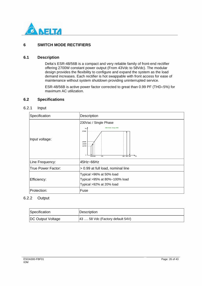
6.1 Description Delta’s ESR-48/56B is a compact and very reliable family of front-end rectifier offering 2700W constant power output (From 43Vdc to 58Vdc). The modular design provides the flexibility to configure and expand the system as the load demand increases. Each rectifier is hot swappable with front access for ease of maintenance without system shutdown providing uninterrupted service.
ESR-48/56B is active power factor corrected to great than 0.99 PF (THD<5%) for maximum AC utilization.
6.2 Specifications
6.2.1 Input
Specification Description
Input voltage:
230Vac / Single Phase
2700W
Po
Vin0
300280
1350W
-40C<Amb. Temp.<55C
17688 29580 85
1303W
1227W
Line Frequency: 45Hz~66Hz
True Power Factor: > 0.99 at full load, nominal line
Efficiency: Typical >96% at 50% load Typical >95% at 80%~100% load Typical >92% at 20% load
Protection: Fuse
6.2.2 Output
Specification Description
DC Output Voltage 43 …. 58 Vdc (Factory default 54V)

ESOA300-FBF01 IOM
Page: 27 of 43
Output Power
58
Vout/Vdc
Iout/A
54
05650
42
48
-40C<Amb. Temp.<55C, Vin is 176Vac~300Vac
35
Efficiency: Typical >96% at 50% load Typical >95% at 80%~100% load Typical >92% at 20% load
Regulation:
Load: ≦± 250mV (load 0~100%)
Line: ≤ ± 50mV
Acoustic: <55 dBA @ 1Meter
Current Sharing ±5% of rated output current≦
6.2.3 Status/Alarm indicators
Item Specifications Remark
LED “AC ON” - Function - Color - On condition - Blink condition 1 - Off condition
indicates the AC line status Green when rectifier is exceed 60V Energy saving mode ‘ON’ for 100ms and ‘OFF’ for 900ms when AC is not available
LED “CL” - Function - Color - On condition - Off condition
Rectifier output current is limited Yellow Rectifier current limited Rectifier not current limited
LED ‘RFA/FF” - Function - Color - On condition - Blink condition 1 - Blink condition 2
- Off condition
Status of the rectifier Red Rectifier fail Rectifier internal communication fail; LED flashes ‘ON’ for 2 seconds and ‘OFF’ for 1 seconds, displaying the flash until the condition release Rectifier fan fail; LED flashes ‘ON’ for 0.25 seconds and ‘OFF’ for 0.25 seconds, displaying the flash until the condition release Rectifier in normal condition

ESOA300-FBF01 IOM
Page: 28 of 43
6.2.4 Environmental
Specification Description
EMI Suppression: EN 55022, class B
EMC Immunity:
Lightning/Surge: EN61000-4-5 level 4, 6KV
ESD
EN 61000-4-2 Contact Discharge 4KV
Air Discharge 8KV
Safety IEC 60950-1, CB certificate, CB scheme, UL/cUL 60950-1, CSA-C22.2, CE mark, TUV Approval
MTBF > 300K hours at 25℃, rated load
6.2.5 Physical
Dimensions (W x H x D) 125.5 x 41.0 x 272.9 / mm (4.94” x 1.61” x 10.74 / inch)
Weight ≈ 1.8 kg / 4 lb
6.3 Outline & Dimensions

ESOA300-FBF01 IOM
Page: 29 of 43
6.4 SMR Operating Principle After applying single phase 220 VAC to the SMR, current is applied to the EMI filter and circulates through protection components such as the AC circuit breaker and the fuse. The major functions of the protection devices are to prevent the SMR from being damaged by surge current and to efficiently reduce the interruption signal of differential mode and common mode, to eliminate the high frequency interruption signal from input current and to prevent the feedback of interruption signal reverse current to the circuit. After the single phase AC current been converted to DC current through bridge rectifier, PFC boost converter, and reaches the requirement of True Power Factor (PF>0.99) (THD<5%) through PFC controller. It generates a 400V DC voltage that is applied to the DC/DC converter. Besides supplying power to all the control circuitry of the SMR, a back current source is established. Through a DC/DC converter, the 400 VDC voltage produces a stable output voltage. The circuitry uses the Full Bridge series resonant converter technique. Using a switching frequency higher than 100 KHz, the 400 VDC is converted to an AC pulse, then through the high frequency transformer, step down, the voltage becomes an appropriate AC pulse width. The stable DC current is yielded by the Secondary AC pulse after flowing through a diode and output filter and is fed back through a DC/DC controller. Before the stable voltage and DC current is delivered by the output of the rectifier, it has been converted by a DC/DC converter, the common mode EMI noise is eliminated by a filter circuit, through an output circuit fuse, to the system in parallel.

ESOA300-FBF01 IOM
Page: 30 of 43
7 OTHER EQUIPMENT IN THE CABINET
7.1 Heat Exchanger The heat exchanger is designed for direct air/air heat removal in cabinet, it can be easy to install in the cabinet The internal and external air circulation loops of the heat exchanger are separated to prevent entry of dust, humidity and dirt. The BHEX HX160-B1 using a internal sensor to monitors the telecom equipment bay temperature and adjusts the fan speeds automatically to reduce noise. The BHEX Internal circuit fan keeps running as long as the BHEX power is on, while the internal circuit air inlet temperature controls external fan on/off status. When the internal circuit air inlet temperature ≧35±2℃ (Fixed), the external fan starts to run. It stops when internal circuit air inlet < 25±2℃ (Fixed). The CCU will issues the “Cooling Fail Alarm” signal via a dry contact when the BHEX failure or power off. The CCU will issues the “Hi Temperature Alarm” signal via a dry contact when the telecom equipment bay temperature > CCU setting threshold. (Default 50 ℃, adjustable)
7.1.1 Spec. Voltage: -48VDC (Nominal) -40 ~ -57VDC (Operating Range) Total heat exchange coefficient: ≧160W/K Max, Power Consumption: 200W (DC)
7.1.2 Indicator & Press Button

ESOA300-FBF01 IOM
Page: 31 of 43
7.1.2.1 Indicator Indicator of the control panel: Normal (Green), Failure (Red), Detecting (Yellow) Indicator of the internal circuit fan: Normal (Green), Failure (Red), Standing-by (Yellow) Indicator of the external circuit fan: Normal (Green), Failure (Red), Standing-by (Yellow) Working indicator: Normal (Green), Failure (Red) Testing indicator: Testing (Green), Normal (Light off) Clean indicator: Cleaning (Green), Normal (Light off)
7.1.2.2 Press Button 1. Maintainer can check the unit use test function: press ‘Test’ button, then the
internal circuit fan and external circuit fan and electricity heater can be all start up mandatory, after function 3 minutes they can automatically restore to the pre-test state. During testing, press this button can also make the unit withdraw from test state. Red light means system has detected failure components and green light means components working normally.
2. Press ‘CLEAN’ button to observe unit running condition 3 minutes, then it will resume to the state before cleaning. During cleaning press ‘CLEAN’ button again, again can exit from testing state and resume to the state before cleaning.
7.1.3 Dimension

ESOA300-FBF01 IOM
Page: 32 of 43
7.2 Humidity Sensor
7.2.1 Spec. Input Voltage : 12Vdc±0.4Vdc Input Current : 20mA-max Humidity sensitivity : 60% ~ 90% ±10% Operation Temperature range : 0~60℃ Storage Temperature range : -20℃~60℃
7.2.2 Pin Assignment
Pin # Name I/O Function Recommended wire gauge
1 +12Vdc O Humidity Power AWG #22
2 Humidity I High Humidity Alarm Signal AWG #22
3 GND I Ground AWG #22
4 Hu-D I Humidity Function Detect Signal AWG #22 Pin 1-3: Power input, +12Vdc ± 0.4Vdc Pin 2-3: High: Open, 5Vdc ± 0.3Vdc, no alarm Low: Short, 0Vdc ± 0.3Vdc, alarm Pin 4-3: Short to GND.
7.2.3 Operation The detection sensitivity of the humidity module is 60% ~ 90%. The default setting of detecting point inside the humidity sensor is 85%. Just push down the Dip-switch to change the detecting range. Note: 1. Never push down the Dip-switch ≧2 to prevent detect error. 2. The detecting range of the sensor is 60% ~ 90%, Setting step is 5%
7.3 Fan Tray The fan module is designed for direct heat removal in cabinet, it can be easy to install in the cabinet with 6 screws. Maximum 4 units can parallel in a system (Depend on front door space). With a NCSU, fan module can be start up itself according to the internal temperature condition. The external air circulation loops of the fan module are filtered by filter to prevent entry of dust and dirt. The Fan Tray via controller NCSU’s ambient sensor to monitors the power system bay internal temperature and control the fan tray on/off automatically. When the temperature > [NCSU setting threshold] (Default 30 ℃, adjustable), the CUS5 will control the fan tray starts to run. It stops when temperature < [NCSU setting threshold -10℃] The NCSU will issues the “Hi Ambient Temperature Alarm” signal via dry contact when the power system bay temperature > NCSU setting threshold. (Default 45 ℃, adjustable)

ESOA300-FBF01 IOM
Page: 33 of 43
7.3.1 Spec. Voltage: 48VDC (Nominal) 40 ~ 59VDC (Operating Range) Current: 1A (Maximum, One Unit Only) 4A (Maximum, Four units in Parallel)
7.3.2 Indicator Indicator: One LED indicator (Green) LED On: Operating ready (Normal condition) LED Off: Fan or power or connection fail condition
7.3.3 Connector Extension Port (CND1) Connector type: 8P Molex Mini-Fit 39-28-8080 or Equivalent
(Mates with Molex 39-01-2085 or Equivalent) Pin assignment: Refer to Table A Power/Control Port (CND2) Connector type: 10P Molex Mini-Fit 39-28-8100 or Equivalent
(Mates with Molex 39-01-2105 or Equivalent) Pin assignment: Refer to Table A
Table A Pin Assignment and Functions of Connectors
Connector Pin No. Function I/O Requested Cable Remark
1 Signal GND Output AWG#22
2 Cable Connection Detect Output AWG#22
3 PWM Control Signal Input AWG#22
4 Fan Operating Control Input AWG#22
5 Fan Operating Control Input AWG#22
6 Fan Fail Alarm Output AWG#22
7 System Power (-48V) Input AWG#18
CND1
(Extension)
8 System Power (0V) Input AWG#18
1 Signal GND Output AWG#22 Note (a)
2 Cable Connection Detect Output AWG#22 Note (a)
3 PWM Control Signal Input AWG#22 Note (b)
4 Fan Operating Control Input AWG#22 Note (c)
5 Fan Fail Alarm Output AWG#22 Note (d)
6 Fan Operating Control Input AWG#22 Note (c)
7 System Power (-48V) Input AWG#20 Note (e)
8 System Power (-48V) Input AWG#20 Note (e)
9 System Power (0V) Input AWG#20 Note (f)
CND2
(Power/Control)
10 System Power (0V) Input AWG#20 Note (f)
ESOA300-FBF01 IOM
Page: 34 of 43
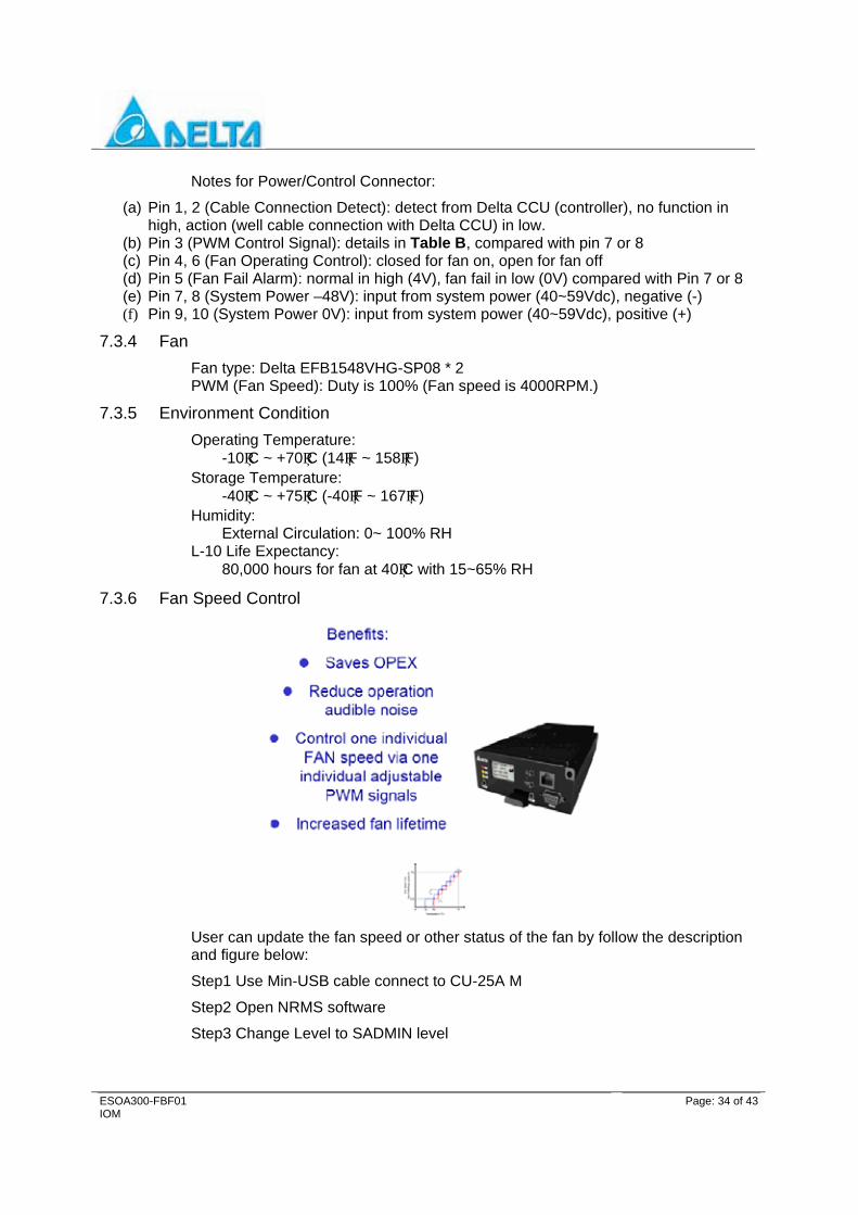
Notes for Power/Control Connector:
(a) Pin 1, 2 (Cable Connection Detect): detect from Delta CCU (controller), no function in high, action (well cable connection with Delta CCU) in low.
(b) Pin 3 (PWM Control Signal): details in Table B, compared with pin 7 or 8 (c) Pin 4, 6 (Fan Operating Control): closed for fan on, open for fan off (d) Pin 5 (Fan Fail Alarm): normal in high (4V), fan fail in low (0V) compared with Pin 7 or 8 (e) Pin 7, 8 (System Power –48V): input from system power (40~59Vdc), negative (-) (f) Pin 9, 10 (System Power 0V): input from system power (40~59Vdc), positive (+)
7.3.4 Fan Fan type: Delta EFB1548VHG-SP08 * 2 PWM (Fan Speed): Duty is 100% (Fan speed is 4000RPM.)
7.3.5 Environment Condition Operating Temperature:
-10°C ~ +70°C (14°F ~ 158°F) Storage Temperature:
-40°C ~ +75°C (-40°F ~ 167°F) Humidity:
External Circulation: 0~ 100% RH L-10 Life Expectancy:
80,000 hours for fan at 40°C with 15~65% RH
7.3.6 Fan Speed Control
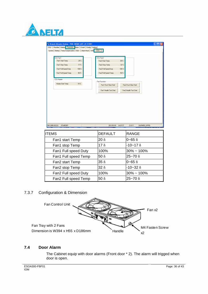
User can update the fan speed or other status of the fan by follow the description and figure below:
Step1 Use Min-USB cable connect to CU-25A M
Step2 Open NRMS software
Step3 Change Level to SADMIN level
ESOA300-FBF01 IOM
Page: 35 of 43
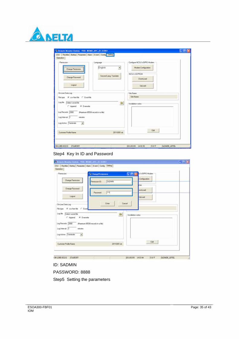
Step4 Key In ID and Password
ID: SADMIN
PASSWORD: 8888
Step5 Setting the parameters
ESOA300-FBF01 IOM
Page: 36 of 43
ITEMS DEFAULT RANGE Fan1 start Temp 20 ℃ 0~65 ℃ Fan1 stop Temp 17 ℃ -10~17 ℃ Fan1 Full speed Duty 100% 30% ~ 100% Fan1 Full speed Temp 50 ℃ 25~70 ℃ Fan2 start Temp 35 ℃ 0~65 ℃ Fan2 stop Temp 32 ℃ -10~32 ℃ Fan2 Full speed Duty 100% 30% ~ 100% Fan2 Full speed Temp 50 ℃ 25~70 ℃
7.3.7 Configuration & Dimension
Fan Tray with 2 Fans Dimension is W394 x H55 x D186mm
M4 Fasten Screw x2
Fan x2
Handle
Fan Control Unit
7.4 Door Alarm The Cabinet equip with door alarms (Front door * 2). The alarm will trigged when door is open.
ESOA300-FBF01 IOM
Page: 37 of 43
8 ALARMS AND TROUBLE SHOOTING
8.1 AC Fail/AC High Voltage / AC Low Voltage Alarm Description There are three (3) AC alarm conditions that are monitored by the system: AC Fail, AC High Voltage and AC Low Voltage. AC fail occurs when AC current is not present at the AC Distribution box. AC high Voltage (ACH) is a factory set parameter and can be adjusted. High Voltage Alarm (ACH) to the desired voltage. All three alarms result in the system shutting down rectifiers until either AC is restored, or the AC voltage returns to levels within the parameter threshold settings (AC High Voltage and AC Low Voltage).
8.1.1 AC Fail, AC Input High(ACH) and AC Input Low (ACL) Alarm Conditions AC Fail: Major Alarm
When the CSU senses the absence of AC current, the CSU will initiate a major alarm. ACL and AC DN Alarm are indicated on the CSU. Battery is in discharge status. The alarm will be re-set to normal condition when AC is restored. During an AC Fail condition, the CSU is power by the reserve batteries.
AC Input High (ACH):
When the CSU senses the input AC Voltage exceeding parameter alarm, the CSU will initiate an AC High Alarm, displayed on the CSU. The system will shut down the rectifiers, however the CSU will operate by the reserve batteries. The CSU will continue to monitor the AC input voltage. The ACH alarm will re-set to the normal operation when AC input voltage decreases within the threshold parameter setting.
AC Voltage Low (ACL):
The AC Voltage Low Alarm occurs when the AC input voltage falls below the threshold set in parameter alarm. When the ACL condition is sensed, an ACL alarm is displayed on the CSU. The CSU will shut down the rectifiers, however the CSU will continue to operate by the reserve batteries. The CSU will continue to monitor the AC input voltage. The ACL alarm will re-set to the normal operation when AC input voltage increases within the threshold parameter setting.
8.1.2 AC Fail Trouble Shooting During an AC Fail condition, the CSU is powered by reserve batteries ad the rectifiers and the rectifiers are shut down. When AC is restored, observe the battery charge current. It may be necessary to decrease the current limit to the charge current range during equalize if a deep discharge situation has occurred.
8.1.3 AC High Voltage (ACH) Trouble shooting Verify the AC input voltage at the AC service pane. If the AC input voltage is higher than the threshold setting, the CSU will take the rectifiers of line. The AC circuit breaker at the AC service panel should be tripped until the AC utility is repaired and the AC input is within input specifications. Verify the AC distribution voltage is higher than the setting value. If not, the system will continue to operate and the CSU may be faulty. The CSU should be swapped
ESOA300-FBF01 IOM
Page: 38 of 43
with a spare. the High Voltage (ACH) parameter set to the desired high voltage threshold setting, and verified that the ACH alarm is cleared. Follow established repair/return policy to have the faulty CSU repaired by Delta.
Do not increase the threshold setting past normal operating input voltages. Operating rectifiers in a High Input Voltage condition can result in seriously damaging the rectifier modules.
8.2 DC Output Voltage High/Low (HV/LV)
8.2.1 DC Output Voltage High Alarm-HV Minor Alarm. This alarm condition exists when the DC output voltage is higher than the parameter alarm setting. The alarm will re-set to the normal condition when the voltage is decreased below the threshold parameter setting. The output voltage can be adjusted via the CSU and at the rectifier. Reference the CSU float voltage parameter rectifier setting and the rectifier equalize Voltage rectifier Setting
8.2.2 DC Output Low Alarm-LV Minor Alarm This alarm condition exists when the DC output voltage is lower than the parameter alarm setting. The alarm will clear when the DC output voltage increases. The output voltage can be adjusted via the CSU and at the rectifier.
8.2.3 DC Voltage High/Low Trouble Shooting Verify the output of each rectifier. If the rectifier output is not within tolerance, swap the rectifier with a spare module, and return the faulty unit to Delta Products for repair. If the output of each rectifier is within tolerance, check the parameters to ensure the correct settings.
8.3 DC Circuit Breaker Tripped Alarm
8.3.1 DC Circuit Breaker Tripped Alarm When a DC load circuit breaker is tripped, the CSU will go into alarm.
Press the alarm button.
Open the DC Distribution Cabinet Door.
Re-set the tripped circuit breaker.
The CSU alarm should clear.
8.3.2 Circuit Breaker Fail Condition Trouble Shooting If the circuit breaker continues to fail: Check the DC Branch load (fed by the DC circuit breaker) to ensure the circuit breaker is the correct size. If the branch load exceeds the circuit breaker rating, the circuit breaker must be changed to a higher rating. Swap with a spare circuit breaker with a higher rating.
ESOA300-FBF01 IOM
Page: 39 of 43
8.4 Over-Temperature Alarm
8.4.1 Temperature-Ambient This alarm is generated when the threshold temperature set in parameter alarm setting TA is exceeded and also controls the Temperature Compensation Voltage Control. The CSU senses the temperature via sensor TA and generates an Ambient Over Temperature Alarm setting – TA.
8.4.2 Over Temperature - Ambient Troubleshooting Verify that the ambient temperature has exceeded the parameter setting by checking the thermostat reading in the hut or equipment room and comparing the reading to the CSU Reading. The CSU will decrease the float voltage for every degree over 25℃ or 77℉ threshold. The CSU will decrease the equalize voltage for every degree below 25℃ or 77℉ threshold. If the TA parameter setting has been exceeded, increase the air conditioning. If the TA threshold is exceeded, it is recommended to turn off the AC Main feeding the Rectifiers until the ambient temperature has decreased below the threshold temperature. If the sensor is defective, turn the Temperature Compensation Feature off. Contact Delta Products for a replacement sensor
Operating the system at excessive temperatures can damage the rectifier.
8.4.3 Over Temperature - Battery Alarm This alarm is generated when the threshold temperature set in parameter TB-1 or TB-2 (if equipped with 2 battery strings) is exceeded. The CSU senses the temperature via sensor TB-1 or TB-2 and generates a Battery Over Temperature Alarm-TB-1 or TB-2.
8.4.4 Over Temperature-Battery Troubleshooting Check the ambient temperature and verify it is within the TA parameter threshold. If the TA and TB-1 & 2 thresholds are not exceeded, check the thermostat reading in the hut or equipment room and comparing the reading to the CSU reading. If the TB-1 or TB-2 sensor is defective, contact Delta Products for a replacement sensor. It is recommended that if the system is in the equalize mode, switch the status to float to reduce the battery temperature.
8.5 Rectifier Fail Alarm When a rectifier fails, the alarm information is sent to the CSU and the rectifier is shut down. The rectifier should be swapped out with a spare unit and the faulty unit returned to Delta Products for repair.
Do not open the rectifier module. There are no serviceable parts. Call Delta Customer Service for an RMA number for repair and return.

ESOA300-FBF01 IOM
Page: 40 of 43
9 MAINTENANCE
9.1 Cleaning and Maintenance
9.1.1 General Special maintenance is not necessary for this shelf, unless the shelf is being operated in a severely harsh environment (dusty environment). The front panels and the cover of the shelf were treated with a special coating, do not use organic cleanser or volatile solvent or corrosion damage may occur. For daily cleaning, brush the dust from the cover and panel. If necessary, use a gentle cleanser or a lightly dampened lint free cloth to remove any dirt or smudges.
9.1.2 Periodic Maintenance Periodic maintenance is not required for normal operation. If necessary, wipe remove dust from the front of the ESR-48/56A A shelf using a lint free, soft cloth an gently wipe the front of the shelf, the CSU and rectifiers. Use a gentle detergent to clean is acceptable.
Do not use spray cleanser to clean the equipment. Using a spray cleanser directly on the equipment can result in serious equipment damage.
Check the DC Bus for heat discoloration. If the bus has any heat discoloration, notify Delta Customer Service.
9.2 Removing and Replacing a Rectifier Module
9.2.1 Removing a Rectifier
Do not touch the DC output Bus when pulling out the SMR module.
The rectifiers are equipped with a pair of safety locker.
Push the both locker to unlock direction to un-lock the rectifier.
Pull out the SMR module slowly from the shelf, using one hand to support the rear half of the SMR and remove the rectifier from the shelf.
ESOA300-FBF01 IOM
Page: 41 of 43
9.2.2 Replacing a Rectifier Install the rectifier module, holding the handle with one hand and using the other to support the rear half of the rectifier module. Place the rectifier in the shelf and push into the shelf.
Do not force the module into the slot. If it does not slide in and connect easily, remove and re-set the unit.
Lock the rectifier by push the locker to the lock direction.
9.2.3 Adding a Rectifier Refer to the procedures in section 9.2.2.
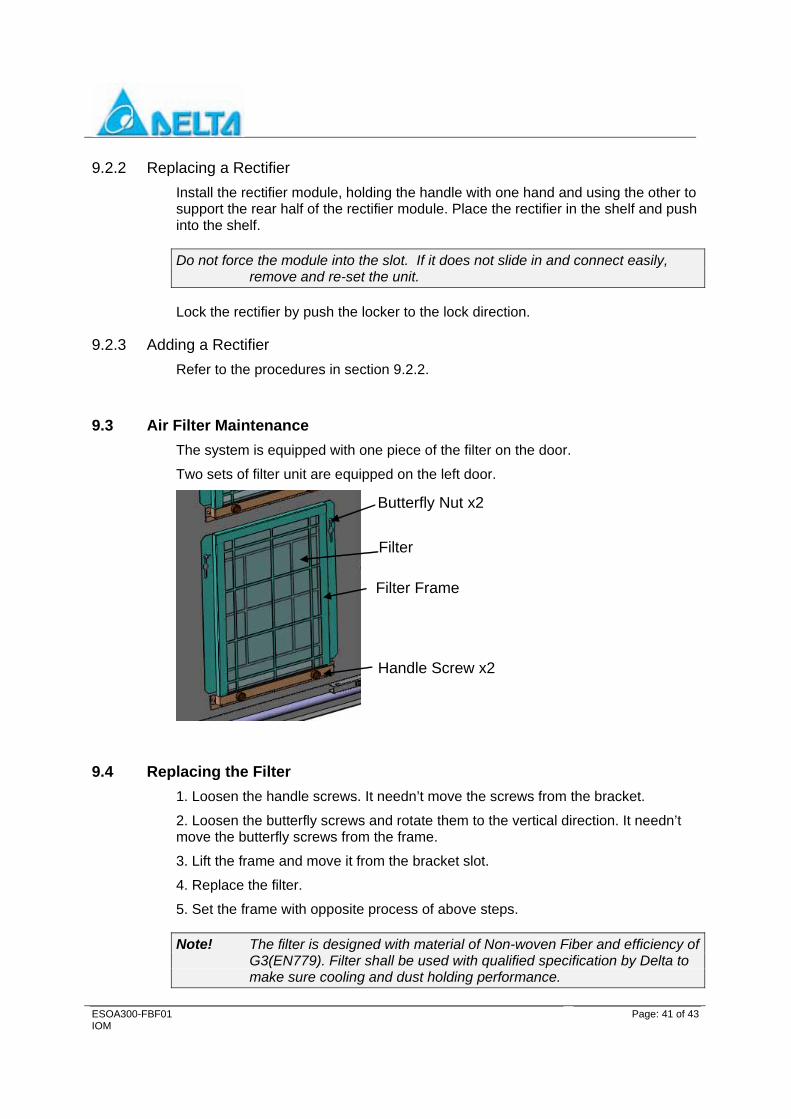
9.3 Air Filter Maintenance The system is equipped with one piece of the filter on the door.
Two sets of filter unit are equipped on the left door.
Handle Screw x2
Butterfly Nut x2
Filter Frame
Filter
9.4 Replacing the Filter 1. Loosen the handle screws. It needn’t move the screws from the bracket.
2. Loosen the butterfly screws and rotate them to the vertical direction. It needn’t move the butterfly screws from the frame.
3. Lift the frame and move it from the bracket slot.
4. Replace the filter.
5. Set the frame with opposite process of above steps.
Note! The filter is designed with material of Non-woven Fiber and efficiency of G3(EN779). Filter shall be used with qualified specification by Delta to make sure cooling and dust holding performance.

ESOA300-FBF01 IOM
Page: 42 of 43
Note! Recommended air filter maintenance:
Note! Clean by vacuum or air jet: 1-2 Month*
Note! Replacement: 6-12 Month*
* The period of filter clean or replacement may be shorter under high ambient pollution (bad air quality)
Warning! DO NOT use water to clean air filter. Air filter clean by water is PROHIBITED.
9.5 Maintenance Notice
To avoid the outdoor system being damaged or causing electrical hazards, the following are suggested measures during/after maintenance.
1. Always keep door closed at any time if no maintenance required to prevent organism intruding.
2. Make sure door is latched and locked properly before leaving to avoid vandalism or water/dust ingress.
3. Do not open door in rainy or bad climate.
4. Only well-trained people can access the system.
5. Use specified or approved component for replacement such as air filter, fan, etc.
6. Follow instruction to perform needed maintenance

ESOA300-FBF01 IOM 2011. 11. 09