Embed Size (px)
Citation preview
FACULTAT DE MEDICINADepartament de Cirurgia
EVALUACIÓN DE LA FIJACIÓN FEMORAL EN LA RECONSTRUCCIÓN
DEL LIGAMENTO CRUZADO ANTERIOR
ESTUDIO EXPERIMENTAL EN MODELO CADAVÉRICO
TESIS DOCTORAL:
Raúl Torres ClaramuntBarcelona, 2014
DIRECTORES:Enric Cáceres Palou
Joan Carles Monllau GarcíaPablo Eduardo Gelber Ghertner

La tesis doctoral titulada;
EVALUACIÓN DE LA FIJACIÓN FEMORAL EN LA RECONSTRUCCIÓN DEL LIGAMENTO CRUZADO ANTERIOR. ESTUDIO EXPERIMENTAL EN MODELO CADAVÉRICO
y presentada por el doctorando;
RAÚL TORRES CLARAMUNT
Está realizada bajo el modelo de compendio de publicaciones cumpliendo la
normativa de la Universitat Autónoma de Barcelona para este tipo de tesis doctorales.
Referencia bibliográfica de los artículos incluidos;
Gelber PE, Reina F, Torres R, Pelfort X, Tey M, Monllau JC. Anatomic single-bundle anterior
cruciate ligament reconstruction from the anteromedial portal: evaluation of transverse
femoral fixation in a cadaveric model. Arthroscopy. 2010 May; 26(5): 651-7.
Gelber PE, Reina F, Torres R, Monllau JC. Effect of femoral tunnel length on the safety of
anterior cruciate ligament graft fixation using cross-pin technique: a cadaveric study. Am J
Sports Med. 2010 Sep; 38(9):1877-84.
Gelber PE, Erquicia J, Abat F, Torres R, Pelfort X, Rodríguez-Baeza A, Alomar X, Monllau
JC. Effectiveness of a footprint guide to establish an anatomic femoral tunnel in anterior
cruciate ligament reconstruction: computed tomograpny evaluation in a cadaveric
model. Arthroscopy. 2011 Jun; 27(6):817-24.


“Cree a aquellos que buscan la verdad. Duda de los que la encuentran”
André Gide


Als meus pares,

8
Evaluación de la fijación femoral en la reconstrucción del ligamento cruzado anterior. Estudio experimental en modelo cadavérico
9
Als meus pares, per ser els grans responsables que hui puga estar jo ací.
A tota la meua família.
A Puçol i tota la gent que allí tinc. Ma casa.
A Gemma per estar sempre ahí, ets el meu suport.
A tots els docents que he tingut en la meua formació acadèmica, tots tenen una part de responsabilitat en que jo puga haver arribat fins ací.
Al Dr. Cáceres, al Dr. Puig, al Dr. Monllau i al Dr. Pelfort, referents durant tota la meua formació profesional.
Al servei de COT del Parc de Salut Mar, Hospital del Mar i de la Esperança; es un plaer anar a treballar cada dia amb tots vosaltres. Gràcies per incentivarme en l´estudi i coneixement de la nostra especialitat.
Al grup de residents de COT del Parc de Salut Mar amb els que he coincidit tots aquests anys. Gràcies a tots vosaltres.
Gracias Pablo, por tu trabajo en esta tesis y por mostrarme tu pasión por el estudio de la rodilla.
AGRADECIMIENTOS

10
Evaluación de la fijación femoral en la reconstrucción del ligamento cruzado anterior. Estudio experimental en modelo cadavérico
11
ÍNDICE
1. INTRODUCCIÓN .....................................................................................15
1.1 LIGAMENTO CRUZADO ANTERIOR ...............................................................17
1.1.1 INTRODUCCIÓN ...................................................................................17
1.1.2 HISTORIA ..............................................................................................17
1.1.3 EMBRIOLOGÍA ......................................................................................18
1.1.4 ANATOMÍA ............................................................................................19
1.1.5 HISTOLOGÍA .........................................................................................20
1.1.6 FUNCIÓN ..............................................................................................20
1.1.7 HAZ ANTEROMEDIAL Y HAZ POSTEROLATERAL ..................................21
1.1.8 ANATOMÍA POSTEROLATERAL RODILLA ...............................................22
1.2 LESIÓN Y REPARACIÓN DEL LIGAMENTO CRUZADO ANTERIOR ................25
1.2.1 PREVALENCIA .......................................................................................25
1.2.2 MECANISMO LESIONAL ........................................................................25
1.2.3 EXPLORACIÓN FÍSICA ...........................................................................25
1.2.4 PRUEBAS DE IMAGEN Y DE ESTABILIDAD .............................................26
1.2.5 HISTORIA DE LA RECONSTRUCCIÓN DEL LIGAMENTO
CRUZADO ANTERIOR ...........................................................................27
1.2.6 TIPOS INJERTOS ....................................................................................29
1.2.7 VARIACIONES TÉCNICAS ......................................................................30
1.2.8 EVOLUCIÓN DE LA UBICACIÓN DEL TÚNEL FEMORAL .........................32
1.2.9 FUNDAMENTO DE LOS TRABAJOS .......................................................35
1.3 HIPÓTESIS DE TRABAJO ................................................................................38
2. MATERIAL Y MÉTODOS........................................................................39
TRABAJO nº1: Anatomic single-bundle anterior cruciate ligament reconstruction
from the anteromedial portal: evaluation of transverse femoral fixation
in a cadaveric model ........................................................................................41
TRABAJO nº2: Effect of femoral tunnel length on the safety of anterior
cruciate ligament graft fixation using cross-pin technique:
a cadaveric study .............................................................................................46
12
Evaluación de la fijación femoral en la reconstrucción del ligamento cruzado anterior. Estudio experimental en modelo cadavérico
TRABAJO nº3: Effectiveness of a footprint guide to establish an anatomic femoral
tunnel in anterior cruciate ligament reconstruction:
computed tomograpny evaluation in a cadaveric model ..................................51
3. RESULTADOS ........................................................................................57
TRABAJO nº1: Anatomic single-bundle anterior cruciate ligament
reconstruction from the anteromedial portal: evaluation of transverse
femoral fixation in a cadaveric model ...............................................................59
TRABAJO nº2: Effect of femoral tunnel length on the safety of anterior
cruciate ligament graft fixation using cross-pin technique:
a cadaveric study .............................................................................................63
TRABAJO nº3: Effectiveness of a footprint guide to establish an anatomic
femoral tunnel in anterior cruciate ligament reconstruction:
computed tomograpny evaluation in a cadaveric model ..................................67
4. DISCUSIÓN ...........................................................................................73
TRABAJO nº1 Y 2:
Anatomic single-bundle anterior cruciate ligament reconstruction
from the anteromedial portal: evaluation of transverse femoral fixation
in a cadaveric model ........................................................................................75
Effect of femoral tunnel length on the safety of anterior cruciate
ligament graft fixation using cross-pin technique: a cadaveric study ................75
TRABAJO nº3: Effectiveness of a footprint guide to establish an anatomic femoral
tunnel in anterior cruciate ligament reconstruction:
computed tomograpny evaluation in a cadaveric model ..................................79
13
5. CONCLUSIONES .....................................................................................81
TRABAJO nº1: Anatomic single-bundle anterior cruciate ligament
reconstruction from the anteromedial portal: evaluation of transverse
femoral fixation in a cadaveric model .................................................................83
TRABAJO nº2: Effect of femoral tunnel length on the safety of anterior
cruciate ligament graft fixation using cross-pin technique:
a cadaveric study ...............................................................................................84
TRABAJO nº3: Effectiveness of a footprint guide to establish an anatomic
femoral tunnel in anterior cruciate ligament reconstruction:
computed tomography evaluation in a cadaveric model ....................................85
6. COPIA DE LOS TRABAJOS .......................................................................87
7. BIBLIOGRAFÍA.......................................................................................113
TRABAJO nº1: Anatomic single-bundle anterior cruciate ligament
reconstruction from the anteromedial portal: evaluation of transverse
femoral fixation in a cadaveric model .................................................................89
TRABAJO nº2: Effect of femoral tunnel length on the safety of anterior
cruciate ligament graft fixation using cross-pin technique:
a cadaveric study ...............................................................................................96
TRABAJO nº3: Effectiveness of a footprint guide to establish an anatomic
femoral tunnel in anterior cruciate ligament reconstruction:
computed tomography evaluation in a cadaveric model ..................................104

14
Evaluación de la fijación femoral en la reconstrucción del ligamento cruzado anterior. Estudio experimental en modelo cadavérico

1515
I N T R O D U C C I Ó N
1. INTRODUCCIÓN

16
Evaluación de la fijación femoral en la reconstrucción del ligamento cruzado anterior. Estudio experimental en modelo cadavérico
17
1. INTRODUCCIÓN
1.1 LIGAMENTO CRUZADO ANTERIOR
1.1.1 INTRODUCCIÓN
El ligamento cruzado anterior (LCA) es un ligamento que se encuentra situado en la ar-
ticulación de la rodilla y actúa como un estabilizador de la misma, limitando el despla-
zamiento anterior y la rotación de la tibia sobre el fémur. El LCA posee además un im-
portante rol en la función propioceptiva de la rodilla debido a las múltiples terminacio-
nes nerviosas que presenta. A finales del siglo XIX se describieron las primeras cirugías
dirigidas a la reparación del LCA, pero ha sido en las últimas dos décadas cuando el
número de estas cirugías ha aumentado de manera muy significativa. El conocimiento
más exhaustivo de la anatomía y función del LCA así como una mejor compresión de la
historia natural de esta lesión han sido los principales responsables en este incremento
en el número de cirugías. Proporcionalmente a este aumento, también se han incre-
mentado significativamente el número de estudios dirigidos a conocer y comprender
mejor la biomecánica, función y reconstrucción de este ligamento. Actualmente el es-
tudio del LCA representa uno de los campos dentro de la cirugía ortopédica que acu-
mula más artículos científicos publicados anualmente.
1.1.2 HISTORIA
La primera referencia anatómica del LCA se remonta a un papiro egipcio del año 3000
a.C. Posteriormente, Hipócrates (460-370 a.C.) describió un episodio de subluxación
de una rodilla humana debido a la lesión de este ligamento. Fue Claudio Galeno de
Pérgamo (131-201 a.C.) quien primero dio nombre a dicha estructura a la cual deno-
minó “ligamentum genu cruciata” (1). Durante muchos decenios el tratamiento y estu-
dio de la lesión de este ligamento no fue prioritaria dentro del campo de la ortopedia,
de manera que pasaron unos 2000 años sin avances significativos en el conocimiento
de esta estructura anatómica. En 1836 se publicó el tratado “Mechanik der menschli-
chen Gehwerkzeuge” por los hermanos Weber, convirtiéndose en el gran referente en
la anatomía y función de los ligamentos cruzados de la rodilla (2). Estos dos hermanos
18
Evaluación de la fijación femoral en la reconstrucción del ligamento cruzado anterior. Estudio experimental en modelo cadavérico
sugirieron que el LCA estaba formado por dos haces de fibras funcionalmente inde-
pendientes. A partir de aquí se fueron produciendo numerosos avances en el conoci-
miento del LCA. William Hey (1736-1818) describió la sensación que posteriormente
pasaría a ser la prueba diagnóstica del “pivot shift”. En 1845 Amadeé Bonnet de Lyon
publicó su “Traité des malaldies des articulations” donde describía los signos indicativos
de una rotura aguda del LCA. En 1875, el médico griego George Noulis describió, en
su tesis titulada “Knee sprains”, una detallada descripción de lo que hoy se cono-
ce como el test de Lachman. El epónimo de este test fue atribuido en 1976 a John
Lachman, basándose en los descubrimientos de Noulis. (3).
Inicialmente el tratamiento conservador fue el tratamiento de elección para esta
lesión. Las rodillas de estos pacientes eran inmovilizadas durante meses obte-
niendo en muchos casos una correcta funcionalidad. En 1900, William Battle pu-
blicó una reparación abierta del LCA usando suturas de seda (4). Sin embargo,
3 años después A.W. Mayo-Robson publicó un caso que se había intervenido 5
años antes, destacando una correcta evolución del paciente (5). Es a este último
autor al que se le atribuye por tanto la primera reparación del LCA. En cambio,
la primera reconstrucción del LCA se atribuye a Ernest W. Hey Groves en 1917 a
partir de una plastia obtenida de la banda iliotibial (6). A partir de aquí, y sobre
todo en la segunda mitad del siglo XX, numerosos avances técnicos llevados a
cabo por la industria y los propios cirujanos han ido modificando y mejorando el
procedimiento quirúrgico (7).
1.1.3 EMBRIOLOGÍA
La rodilla procede del mesénquima femoral y tibial y se forma a partir de la cuarta
semana de gestación. En este momento los fibroblastos inician su alineación for-
mando el eje inicial del LCA. A las 9 semanas de gestación el LCA está compuesto
de numerosos fibroblastos inmaduros capaces de producir matriz extracelular.
Después de la 20ª semana, el desarrollo consiste en un marcado crecimiento con
19
pequeños cambios en la forma (8). Sobre la diferenciación de los diferentes ha-
ces del LCA, en un trabajo artroscópico realizado por Tena-Arregui (9), se aprecia
la presencia de estos haces entre las semana 24ª y 40ª de gestación pero pare-
cen tener una disposición más paralela que cuando se comparan con la orienta-
ción del LCA del adulto.
1.1.4 ANATOMÍA
El LCA, al igual que el ligamento cruzado posterior (LCP), es un ligamento intra-
capsular y extrasinovial ya que está recubierto de una membrana sinovial (10). El
LCA se origina en la cara medial del cóndilo femoral externo y desciende anterior
y medialmente hasta su inserción en la meseta tibial. La inserción femoral se si-
túa por detrás de la escotadura intercondílea en forma semicircular. La porción
anterior de la inserción es prácticamente recta y la porción posterior es convexa.
Durante su trayecto descendente el LCA sufre una rotación externa hasta su in-
serción tibial. Esta inserción es oblicua en la cara lateral de la tuberosidad tibial
interna a nivel de la fosa intercondílea. La longitud media del LCA es de 38 mm y su
anchura media es de 11 mm.
El LCA se divide en dos haces que toman su nombre de la inserción tibial: el haz antero-
medial (AM) y el haz posterolateral (PL). El haz AM se inserta en la región más anterior
y medial de la inserción tibial y en la región más cefálica de la huella femoral. Por el
contrario, el haz PL se inserta más posteriormente en la tibia y más anterior y lateral
en el fémur. Esta división de haces sería más funcional que anatómica según algunos
autores (11).
Los resultados obtenidos por Odensten y Gillquist en cadáver mostraron que el LCA
no es un ligamento uniforme en su diámetro. La inserción en el cóndilo femoral lateral
es oval con un diámetro máximo de 18±2 milímetros y un diámetro mínimo de 11±2
20
Evaluación de la fijación femoral en la reconstrucción del ligamento cruzado anterior. Estudio experimental en modelo cadavérico
milímetros. La distancia desde el punto central del área de inserción femoral del LCA
a la pared posterior del cóndilo es de 15,3±3 mm. La inserción en la tibia también tie-
ne una morfología oval con un eje máximo mayor de 17±3 y mínimo menor de 11±2.
Esta inserción tiene dos estructuras con las que se relaciona íntimamente: la inserción
anterior del menisco lateral, que está alineada con el origen del fascículo anterolateral
del LCA, y el LCP, cuyo borde anterior estaría situado unos 7 mm posterior a la inserción
tibial del LCA. (11-13).
1.1.5 HISTOLOGÍA
El LCA está formado por una amplia red de colágeno que representa aproximadamen-
te dos tercios de su peso en seco. La mayor parte de este colágeno es de tipo I (90%)
y el restante equivale al tipo III (10%). El colágeno se dispone en múltiples haces de
fibras de 20 µm de anchura agrupados en fascículos de 20 µm a 400 µm de diámetro
(10). El tercio restante del peso seco del LCA está formado por fibroblastos y otras sus-
tancias como elastina (<5%) y proteoglicanos (1%). El agua representa el 60% del peso
neto en condiciones fisiológicas. Las inserciones óseas de los ligamentos y tendones
presentan una estructura con fibras de colágeno que se continúan directamente con
fibras situadas en el seno del hueso.
1.1.6 FUNCIÓN
El LCA actúa como principal estabilizador estático de la rodilla, impidiendo la trasla-
ción anterior de la tibia sobre el fémur, alcanzando el 86% de la fuerza que se opone a
dicho movimiento (10). Cómo se ha comentado previamente, algunos autores como
Odensten (11) no encuentran una separación anatómica entre los dos haces. Sin em-
bargo, otros como Amis y cols. (14), incluso sugirieron la presencia de un tercer haz
que se denominaría haz intermedio. La diferenciación del LCA en dos fascículos fun-
cionales, el AM y el PL, parece ser una simplificación de la anatomía del LCA, pero esta
descripción de las fibras del LCA ha sido universalmente aceptada como la mejor y más
pragmática descripción anatómica y sobre todo funcional de este ligamento. Además,

21
el LCA tiene una rotación externa fisiológica que se incrementa a medida que la rodilla
es flexionada, y se debe a la orientación de sus inserciones óseas.
La función de estabilizador en el plano sagital es conocida desde hace muchas
décadas, sin embargo la importancia de este ligamento en el control de la esta-
bilidad rotacional de la rodilla ha sido reconocida sobre todo en las últimas dos
décadas. El LCA se tensa durante el movimiento de flexo-extensión de la rodilla
de manera que se limita la hiperextensión de la articulación. El LCA también ac-
túa como un estabilizador secundario en los movimientos de varo-valgo.
1.1.7 HAZ ANTEROMEDIAL Y HAZ POSTEROLATERAL
El haz AM tiene una orientación más vertical, de aproximadamente 70º a la base de la
rodilla. Su inserción está en la parte más anterior de la inserción tibial y en la parte más
superior de la inserción femoral. Este haz está más tenso con la rodilla flexionada a 90º
que con la rodilla en extensión, coincidiendo con una mayor laxitud del haz PL. Por
lo tanto en flexión, el haz AM se vuelve dominante a la hora de resistir a la translación
anterior de la tibia y en extensión esta función recae en mayor medida sobre el haz PL.
En cuanto a la estabilidad rotatoria, al haz PL se le atribuye una mayor importancia que
al haz AM (15). La inserción del haz AM en el fémur se encuentra en una posición más
alta que el haz PL, que tiene una inserción más baja y anterior.
La inserción tibial es la que da nombre a cada uno de los dos haces del ligamento. Esta
inserción tiene un borde anterior a unos 10-14 milímetros detrás del borde anterior de
la tibia y se extiende entre la espina tibial medial y lateral. El centro de la inserción del
haz AM está en íntima relación con el cuerno anterior del menisco lateral, mientras que
el centro de la inserción del haz PL tiene una distancia de 7 a 8 milímetros anterior al
origen del LCP (Figura 1).
22
Evaluación de la fijación femoral en la reconstrucción del ligamento cruzado anterior. Estudio experimental en modelo cadavérico
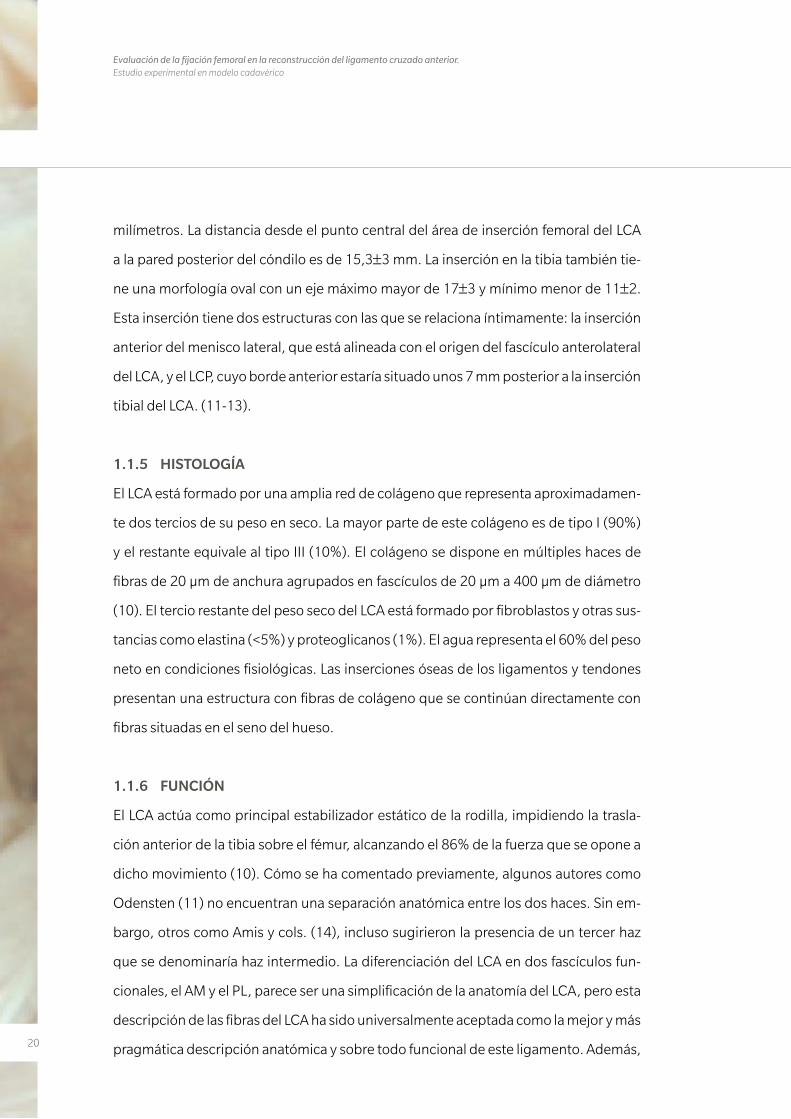
Figura 1. Haz PL y AM con la rodilla en extensión (a) y con la rodilla en flexión (b). Durante la extensión ambos haces están paralelos hallándose una mayor tensión en el haz PL. Durante la flexión ambos haces se entrecru-zan y el haz AM se encuentra con mayor tensión. (De Sebastian Kopf y cols. Imagen reproducida con permiso de Knee Surgery Sports Traumatology Arthroscopy Journal)
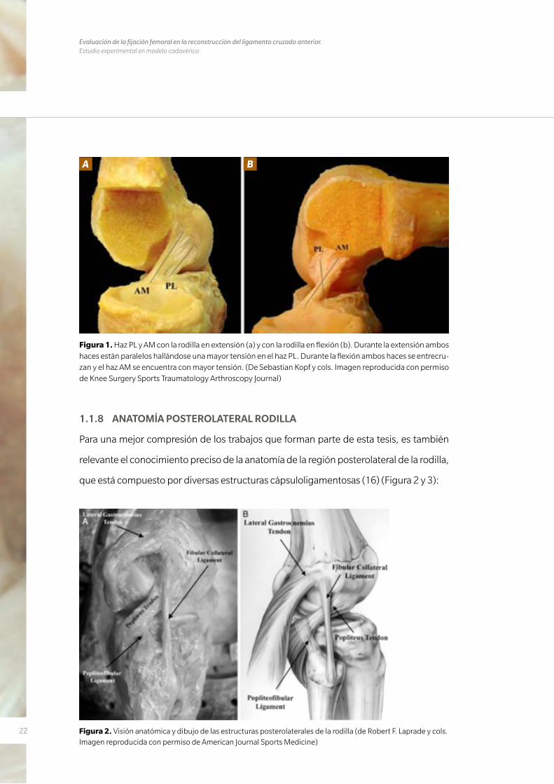
1.1.8 ANATOMÍA POSTEROLATERAL RODILLA
Para una mejor compresión de los trabajos que forman parte de esta tesis, es también
relevante el conocimiento preciso de la anatomía de la región posterolateral de la rodilla,
que está compuesto por diversas estructuras cápsuloligamentosas (16) (Figura 2 y 3):
Figura 2. Visión anatómica y dibujo de las estructuras posterolaterales de la rodilla (de Robert F. Laprade y cols. Imagen reproducida con permiso de American Journal Sports Medicine)
A B
23
• Elmúsculosemimembranosotieneunaampliainserciónenlaparteposteriorde
la rodilla. Se han descrito hasta 8 inserciones distales a nivel de la tibia y del fémur.
En su mayoría, este complejo se inserta fundamentalmente en el complejo poste-
romedial de la rodilla, pero alguna de estas inserciones forman parte de la región
posterolateral de la misma.
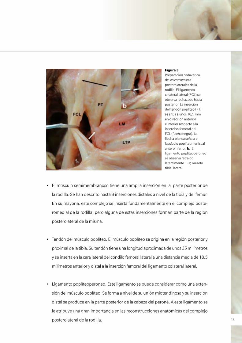
• Tendóndelmúsculopoplíteo.Elmúsculopoplíteoseoriginaenlaregiónposteriory
proximal de la tibia. Su tendón tiene una longitud aproximada de unos 35 milímetros
y se inserta en la cara lateral del cóndilo femoral lateral a una distancia media de 18,5
milímetros anterior y distal a la inserción femoral del ligamento colateral lateral.
• Ligamentopoplíteoperoneo.Esteligamentosepuedeconsiderarcomounaexten-
sión del músculo poplíteo. Se forma a nivel de su unión miotendinosa y su inserción
distal se produce en la parte posterior de la cabeza del peroné. A este ligamento se
le atribuye una gran importancia en las reconstrucciones anatómicas del complejo
posterolateral de la rodilla.
Figura 3. Preparación cadavérica de las estructuras posterolaterales de la rodilla: El ligamento colateral lateral (FCL) se observa rechazado hacia posterior. La inserción del tendón poplíteo (PT) se sitúa a unos 18,5 mm en dirección anterior e inferior respecto a la inserción femoral del FCL (flecha negra). La flecha blanca señala el fascículo poplíteomeniscal anteroinferior, b. El ligamento poplíteoperoneo se observa retraído lateralmente. LTP, meseta tibial lateral.
24
Evaluación de la fijación femoral en la reconstrucción del ligamento cruzado anterior. Estudio experimental en modelo cadavérico
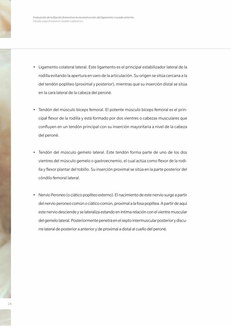
• Ligamentocolaterallateral.Esteligamentoeselprincipalestabilizadorlateraldela
rodilla evitando la apertura en varo de la articulación. Su origen se sitúa cercana a la
del tendón poplíteo (proximal y posterior), mientras que su inserción distal se sitúa
en la cara lateral de la cabeza del peroné.
• Tendóndelmúsculobícepsfemoral.Elpotentemúsculobícepsfemoraleselprin-
cipal flexor de la rodilla y está formado por dos vientres o cabezas musculares que
confluyen en un tendón principal con su inserción mayoritaria a nivel de la cabeza
del peroné.
• Tendóndelmúsculogemelo lateral. Este tendón formapartedeunode losdos
vientres del músculo gemelo o gastroecnemio, el cual actúa como flexor de la rodi-
lla y flexor plantar del tobillo. Su inserción proximal se sitúa en la parte posterior del
cóndilo femoral lateral.
• NervioPeroneo(ociáticopoplíteoexterno).Elnacimientodeestenerviosurgeapartir
del nervio peroneo común o ciático común, proximal a la fosa poplítea. A partir de aquí
este nervio desciende y se lateraliza estando en íntima relación con el vientre muscular
del gemelo lateral. Posteriormente penetra en el septo intermuscular posterior y discu-
rre lateral de posterior a anterior y de proximal a distal al cuello del peroné.
25
1.2 LESIÓN Y REPARACIÓN DEL LIGAMENTO CRUZADO ANTERIOR
1.2.1 PREVALENCIA
La reconstrucción del LCA representa la cirugía ligamentosa más frecuente. En EEUU
se realizan más de 150.000 intervenciones quirúrgicas de este ligamento al año (17).
En España, esta cifra es de unas 15.000 cirugías al año (7). Una mayor participación en
actividades lúdicas y deportivas en la sociedad actual ha hecho que aumente el núme-
ro de lesiones de este ligamento, ya que la mayoría de estas se producen en un con-
texto deportivo. Paralelamente, la evolución de las técnicas quirúrgicas empleadas en
su reconstrucción así como la experiencia y conocimiento de los cirujanos en cuanto
a la historia natural y secuelas de esta lesión cuando no es reparada, ha hecho que se
incremente el número de reconstrucciones de LCA realizadas anualmente.
1.2.2 MECANISMO LESIONAL
La mayoría de lesiones se producen por un mecanismo indirecto (72%), mientras que
en el resto se describe un traumatismo directo. El mecanismo más frecuente es con la
rodilla en extensión o hiperextensión con un movimiento repentino de desaceleración
previo a un cambio de dirección realizando rotación externa de la tibia con valgo de la
rodilla (18).
La mayoría de lesiones de este ligamento se producen en deportistas o en personas
que practican deportes ocasionalmente. Los deportes más implicados con esta lesión
son aquellos que precisan de un pivotaje del fémur respecto a la tibia, como pueden
ser el fútbol, el rugby, el baloncesto y el tenis entre otros.
1.2.3 EXPLORACIÓN FÍSICA
Las pruebas físicas descritas para identificar una inestabilidad en la rodilla causada por
una rotura del LCA se dividen en dos: estáticas y dinámicas. En cuanto a las estáticas,
estas valoran la estabilidad anteroposterior provista por el LCA. La prueba de Lachman
26
Evaluación de la fijación femoral en la reconstrucción del ligamento cruzado anterior. Estudio experimental en modelo cadavérico
(también llamada Noulis) y la prueba del cajón anterior aplican una fuerza desde pos-
terior hacia anterior a la tibia a 30º y 90º de flexión respectivamente (19), y son más
sensibles teóricamente para evaluar una lesión del haz AM. En cuanto a las pruebas
dinámicas destacamos la prueba del pívot shift que, desde el punto de vista teórico,
centra su valoración hacia el haz PL y la estabilidad rotatoria de la rodilla. Esta se realiza
con la rodilla en extensión completa, aplicando estrés en valgo a la tibia proximal junto
a una rotación interna de la pierna. Se inicia la flexión de la rodilla, y el platillo tibial se
desplaza anteriormente y se reduce sobre el cóndilo femoral con un resalte percibible
por el explorador. El examen físico de la rodilla debe completarse con el estudio de
posibles lesiones asociadas.
1.2.4 PRUEBAS DE IMAGEN Y DE ESTABILIDAD
La generalización de la resonancia magnética (RM) ha permitido confirmar las lesiones
del LCA mediante una prueba de imagen que presenta una elevada precisión (97%)
en el diagnóstico de estas lesiones cuando son completas y algo considerablemente
menor, en el rango del 28% al 82%, cuando son incompletas (20, 21). Además, esta
prueba es capaz de aportarnos información sobre la existencia de otras lesiones aso-
ciadas. Sin embargo, son la anamnesis y la exploración física las que nos tiene que ha-
cer pensar en una lesión del LCA.
El uso del artrómetro KT-1000 (Medmetric, San Diego, CA, USA) o de las radiografías
forzadas a 30º, en las que se provoca un cajón anterior, también nos dan información
sobre la lesión del LCA y el grado de inestabilidad anteroposterior que causa dicha
lesión. Objetivar la inestabilidad rotacional de la rodilla tras la rotura del LCA es más
complejo y normalmente se describe mediante una prueba clínica subjetiva, y alta-
mente dependiente del grado de relajación de cada paciente, como es el Pívot Shift. Sin
embargo, en los últimos años, hay numerosos intentos de valorar esta prueba también
mediante artrometría.

27
1.2.5 HISTORIA DE LA RECONSTRUCCIÓN DEL LIGAMENTO CRUZADO
ANTERIOR
En 1895 se describió la primera reparación del LCA realizada en el Reino Unido por
A.W. Mayo Robson. Unos años más tarde, el también británico, Ernest W. Hey Groves
realizó la primera reconstrucción del mismo con plastia autóloga obtenida de la fascia
lata. A partir de aquí, diversos autores fueron realizando diferentes aportaciones a la
cirugía dirigida a reconstruir el LCA. En 1963, Kenneth G. Jones (22), aplicando los co-
nocimientos obtenidos por otros autores como Ernst Gold, Arnold Wittek o Campbell,
generalizó el uso del tendón rotuliano como injerto para reparar el LCA. Su técnica im-
plicaba obtener una pastilla ósea proveniente de la rótula unida al tercio medio del ten-
dón rotuliano dejando su inserción en la tuberosidad anterior de la tibia (TTA) intacta.
En esta técnica, con el fin de evitar problemas con la longitud del injerto, el autor tras-
ladó la ubicación del túnel femoral al intercóndilo justo posterior al cartílago articular.
En Estados Unidos el uso de este procedimiento para la reparación del LCA fue conoci-
do como la técnica de Jones. Esta técnica fue modificada posteriormente por diferen-
tes autores describiéndose diversas variantes de la misma, como (23) usar solamente
el tendón rotuliano sin pastilla ósea o no liberar la parte de la tuberosidad anterior de
la tibia realizando un túnel a partir de aquí. Frankle, en 1969, fue el pionero en utilizar
el tendón rotuliano como plastia libre a la hora de reparar lesiones de LCA, así como
describir las lesiones condrales originadas a partir de una reparación demasiado tardía
del LCA. Posteriormente, Marshall (24) unió a este tercio central del tendón rotuliano
la fascia prepatelar y la porción central del cuadriceps. Otros autores como Clancy (25,
26), Noyes (27, 28), Dejour (29), Rosenberg o Gillquist (30) realizaron, a principios de
los años 80, diferentes aportaciones a la reconstrucción del LCA (Figura 4).
28
Evaluación de la fijación femoral en la reconstrucción del ligamento cruzado anterior. Estudio experimental en modelo cadavérico
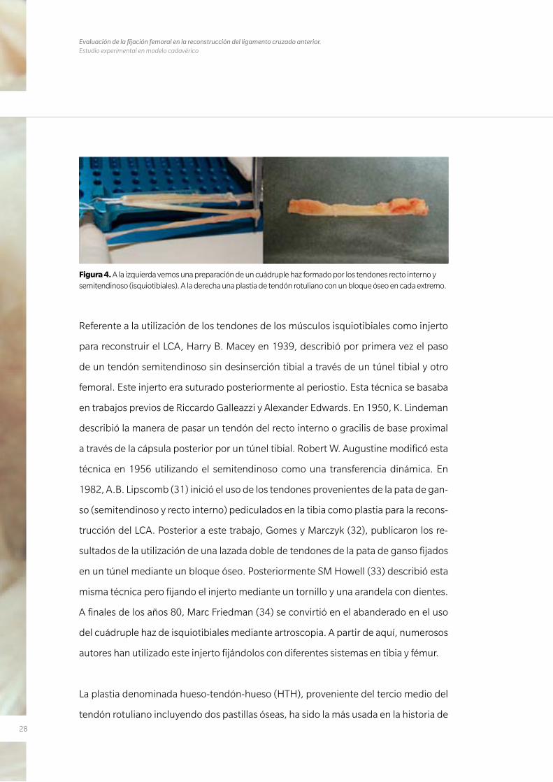
Figura 4. A la izquierda vemos una preparación de un cuádruple haz formado por los tendones recto interno y semitendinoso (isquiotibiales). A la derecha una plastia de tendón rotuliano con un bloque óseo en cada extremo.
Referente a la utilización de los tendones de los músculos isquiotibiales como injerto
para reconstruir el LCA, Harry B. Macey en 1939, describió por primera vez el paso
de un tendón semitendinoso sin desinserción tibial a través de un túnel tibial y otro
femoral. Este injerto era suturado posteriormente al periostio. Esta técnica se basaba
en trabajos previos de Riccardo Galleazzi y Alexander Edwards. En 1950, K. Lindeman
describió la manera de pasar un tendón del recto interno o gracilis de base proximal
a través de la cápsula posterior por un túnel tibial. Robert W. Augustine modificó esta
técnica en 1956 utilizando el semitendinoso como una transferencia dinámica. En
1982, A.B. Lipscomb (31) inició el uso de los tendones provenientes de la pata de gan-
so (semitendinoso y recto interno) pediculados en la tibia como plastia para la recons-
trucción del LCA. Posterior a este trabajo, Gomes y Marczyk (32), publicaron los re-
sultados de la utilización de una lazada doble de tendones de la pata de ganso fijados
en un túnel mediante un bloque óseo. Posteriormente SM Howell (33) describió esta
misma técnica pero fijando el injerto mediante un tornillo y una arandela con dientes.
A finales de los años 80, Marc Friedman (34) se convirtió en el abanderado en el uso
del cuádruple haz de isquiotibiales mediante artroscopia. A partir de aquí, numerosos
autores han utilizado este injerto fijándolos con diferentes sistemas en tibia y fémur.
La plastia denominada hueso-tendón-hueso (HTH), proveniente del tercio medio del
tendón rotuliano incluyendo dos pastillas óseas, ha sido la más usada en la historia de
29
esta cirugía. Sin embargo, la morbilidad que este injerto genera en la zona donante y
que conduce con frecuencia a dolor residual en la cara anterior de la rodilla, ha propi-
ciado el notable incremento en la utilización de la plastia proveniente de los tendones
de los músculos isquiotibiales en los últimos años.
1.2.6 TIPOS INJERTOS
Diferentes tipos de injertos se han descrito para reconstruir un LCA. Estos se dividen
en autoinjertos o aloinjertos. El aloinjerto proviene de un banco de tejidos y puede ser
un tendón rotuliano con una pastilla ósea tibial y otra de la rótula, un tendón de Aqui-
les, un tendón cuadricipital o un tendón tibial posterior entre otros.
En cuanto a los injertos autólogos, como ya hemos mencionado en el apartado an-
terior, el más usado en los últimos años es la plastia proveniente de tendón rotuliano
con una pastilla ósea en su extremo proximal de la rótula y otra distal de la tuberosidad
tibial anterior. Esta plastia aporta teóricamente una mejor integración de los extremos
de la plastia a la tibia y al fémur ya que esta integración es hueso-hueso (35).
La alternativa más utilizada, la formada por los tendones de los músculos gracilis y se-
mitendinoso, no posee pastilla ósea en sus extremos, por lo que en teoría la integración
en los túneles óseos demora más tiempo en producirse. Sin embargo los resultados fun-
cionales y histológicos obtenidos han demostrado ser similares a los obtenidos con la
plastia proveniente del tendón rotuliano (36, 37). Como se ha comentado previamente,
esta plastia presenta como principal ventaja, una menor morbilidad de la zona donante
en comparación al HTH.
La tercera plastia autóloga más usada es la que proviene del tendón cuadricipital, ósea
proveniente del polo superior de la rótula. Esta plastia no tiene la popularidad de las
dos anteriores y se suele dejar como alternativa en casos de revisión o cuando las fuen-
tes para obtener las otras dos plastias están comprometidas.
30
Evaluación de la fijación femoral en la reconstrucción del ligamento cruzado anterior. Estudio experimental en modelo cadavérico
El uso de plastias provenientes de un banco de tejidos se ha convertido en los últimos
años en la primera opción en muchos centros, sobre todo en Estados Unidos. Aunque
no se puede descartar definitivamente la posibilidad de transmitir algún tipo de en-
fermedad viral, el uso de esta plastia se considera una alternativa válida sobre todo en
cirugías de fracaso de una plastia de LCA.
1.2.7 VARIACIONES TÉCNICAS
Como se ha comentado anteriormente, son muchos los trabajos sobre el LCA que
han sido publicando en las últimas dos décadas, mejorando notablemente la téc-
nica quirúrgica. Además, son numerosas las opciones tecnológicas que la industria
ha ido ofreciendo a la hora de realizar las fijaciones de las diferentes plastias tanto
a nivel femoral como tibial. Pero, sin duda alguna, el gran avance de la última dé-
cada es haber retomado el concepto de la reconstrucción anatómica del LCA. Este
concepto afecta sobre todo a la ubicación del túnel femoral en el cóndilo femoral
lateral. Para el preciso reconocimiento quirúrgico del sitio anatómico donde reali-
zar los túneles, es esencial para el cirujano tener un conocimiento muy exacto de la
anatomía de las inserciones del LCA. El método más usado para indicar y referirse al
sitio donde se realiza el túnel femoral ha sido tradicionalmente el denominado sis-
tema de la esfera horaria, en el que un reloj imaginario se superpone al hemicírculo
del techo del intercóndilo y cada hora representa una ubicación determinada. De
esta manera, en una rodilla derecha, las 12 hs. se ubicaría en la parte más superior
de la escotadura intercondílea, y las 9 hs. en la parte más lateral y baja del cóndi-
lo femoral lateral (equivaldría a las 3 hs. en la rodilla izquierda). Este método está
discutido pues sólo considera un plano a la hora de definir la ubicación del túnel
femoral, cuando olvida el plano sagital ya que obviamente la rodilla es una estruc-
tura tridimensional (38). El túnel femoral se realiza de forma más común mediante 2
técnicas diferentes: a través del túnel tibial (previamente labrado para la realización
del túnel tibial) o a través de un portal artroscópico anteromedial. La primera se de-
nomina como técnica monotúnel (porque se hacen ambos túneles en continuado
31
entre ambos túneles) y la segunda es una técnica bitúnel (porque el túnel tibial y el
femoral se realizan de forma independiente).
Otra disyuntiva es si se realiza un único túnel femoral, y por lo tanto se reconstruye
un único fascículo del LCA (monofascicular), o se realizan dos túneles (bifascicular)
ateniéndonos a la constitución en dos haces del LCA. La opción bifascicular es menos
usada pues no ha demostrado diferencias funcionales con el túnel único y es mucho
más exigente técnicamente además que duplica los costos en material de fijación (39,
40). Cualquiera sea el caso, parece que lo importante es la realización de los túneles
en el lugar anatómico donde previamente se encontraba el ligamento nativo, es decir,
restituir lo más fielmente al ligamento que se encontraba en la rodilla.
En cuanto al túnel tibial, este se realiza desde la parte anteromedial de la tibia proximal
con control artroscópico para controlar el punto de salida intraarticular, que debe ser
a nivel de la huella o fibras remanentes de la inserción del LCA nativo. Podemos variar
el grado de angulación del túnel tanto en el plano coronal como sagital, pero normal-
mente este túnel suele tener una angulación de unos 55º en el plano sagital y unos 20º
en el plano coronal, iniciándose entre uno y dos centímetros medial a la tuberosidad
tibial anterior.
Tras la realización de los túneles, y tras haber pasado la plastia, tenemos varios siste-
mas para fijar la plastia a la tibia y al fémur. El uso de grapas metálicas, de tornillos me-
tálicos o de los más recientes tornillos reabsorbibles interferenciales son algunos de
estos sistemas. En el caso de usar plastias proveniente de tendones isquiotibiales, para
la fijación tibial podemos usar cualquiera de los sistemas mencionados (normalmente
un tornillo interferencial), pero para la fijación femoral este sistema de fijación no se
usa tan frecuentemente. Para ello la industria ha creado diferentes tipos de anclaje. Los
dos sistemas más utilizados para realizar esta fijación femoral son los de suspensión
cortical y los de fijación transversal. Los sistemas de fijación transversal ofrecen una
32
Evaluación de la fijación femoral en la reconstrucción del ligamento cruzado anterior. Estudio experimental en modelo cadavérico
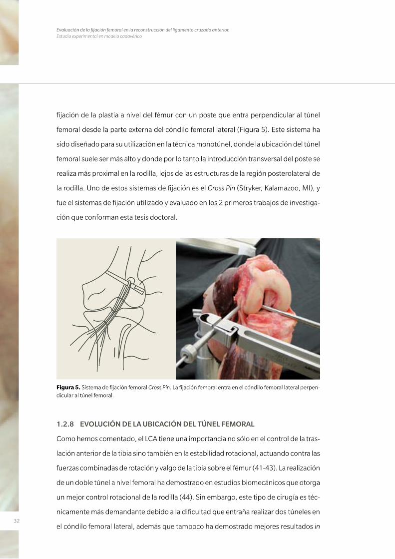
fijación de la plastia a nivel del fémur con un poste que entra perpendicular al túnel
femoral desde la parte externa del cóndilo femoral lateral (Figura 5). Este sistema ha
sido diseñado para su utilización en la técnica monotúnel, donde la ubicación del túnel
femoral suele ser más alto y donde por lo tanto la introducción transversal del poste se
realiza más proximal en la rodilla, lejos de las estructuras de la región posterolateral de
la rodilla. Uno de estos sistemas de fijación es el Cross Pin (Stryker, Kalamazoo, MI), y
fue el sistemas de fijación utilizado y evaluado en los 2 primeros trabajos de investiga-
ción que conforman esta tesis doctoral.
Figura 5. Sistema de fijación femoral Cross Pin. La fijación femoral entra en el cóndilo femoral lateral perpen-dicular al túnel femoral.
1.2.8 EVOLUCIÓN DE LA UBICACIÓN DEL TÚNEL FEMORAL
Como hemos comentado, el LCA tiene una importancia no sólo en el control de la tras-
lación anterior de la tibia sino también en la estabilidad rotacional, actuando contra las
fuerzas combinadas de rotación y valgo de la tibia sobre el fémur (41-43). La realización
de un doble túnel a nivel femoral ha demostrado en estudios biomecánicos que otorga
un mejor control rotacional de la rodilla (44). Sin embargo, este tipo de cirugía es téc-
nicamente más demandante debido a la dificultad que entraña realizar dos túneles en
el cóndilo femoral lateral, además que tampoco ha demostrado mejores resultados in
33
vivo que la realización de un túnel único en el fémur y por tanto un único fascículo (45).
Si a esto sumamos el mayor coste de esa técnica, encontramos el porqué esta técnica
bifascicular está cayendo cada día más en desuso, de manera que la realización de un
único túnel se está convirtiendo en la regla a la hora de reconstruir el LCA.
Inicialmente, con la idea de mantener la isometría de la plastia en cualquier grado de
flexión de la rodilla, se sacrificó el concepto anatómico de túnel femoral por el con-
cepto isométrico del mismo. Por esto la ubicación de este túnel femoral se realizó his-
tóricamente en una posición alta en el intercóndilo (46, 47). Con esta ubicación del
túnel, se restituye de manera efectiva la estabilidad anteroposterior de la tibia sobre el
fémur, pero no es tan efectiva en restituir la estabilidad rotacional. En la última década,
diferentes estudios anatómicos (48-50) han demostrado que un descenso del túnel
femoral hacía una ubicación más anatómica del mismo, proporciona un mejor control
de la estabilidad rotacional sin sacrificar la restitución de la estabilidad anteroposterior
(42, 51, 52).
A la hora de hablar de la ubicación del túnel femoral, en los últimos años se ha co-
menzando a dar importancia no solo al plano coronal, sino también al plano sagital.
Mientras el plano coronal se describía como se ha comentado previamente con el sis-
tema de referencia horaria (ahora denominado alto/bajo), tenemos que tener en cuen-
ta también la ubicación del túnel femoral en el plano sagital, atendiendo al concepto
superficial (más cercano a la cortical anterior del fémur con la rodilla a 90º de flexión)/
profundo (si el túnel queda más cercano a la cortical posterior del fémur con la rodilla
a 90º de flexión). A partir de aquí, se han descrito numerosos estudios a la hora de de-
finir las localizaciones de los túneles femorales cuando realizamos una reconstrucción
anatómica del LCA (53, 54).
La ubicación anatómica del túnel femoral requiere una ubicación más baja en el plano
coronal y más superficial en el plano sagital del que históricamente se venía utilizando.
La técnica transtibial o monotúnel se ha demostrado de forma reiterada como ineficaz
34
Evaluación de la fijación femoral en la reconstrucción del ligamento cruzado anterior. Estudio experimental en modelo cadavérico
o al menos dificultosa para ubicar el túnel femoral en su posición anatómica de forma
fiable y reproducible, sin el riesgo de lesionar el cartílago de la meseta tibial medial o
de lesionar el ligamento colateral medial (55, 56). Debido a esto, se aconseja acceder
al sitio anatómico del planificado túnel femoral desde un portal artroscópico antero-
medial bajo (57, 58).
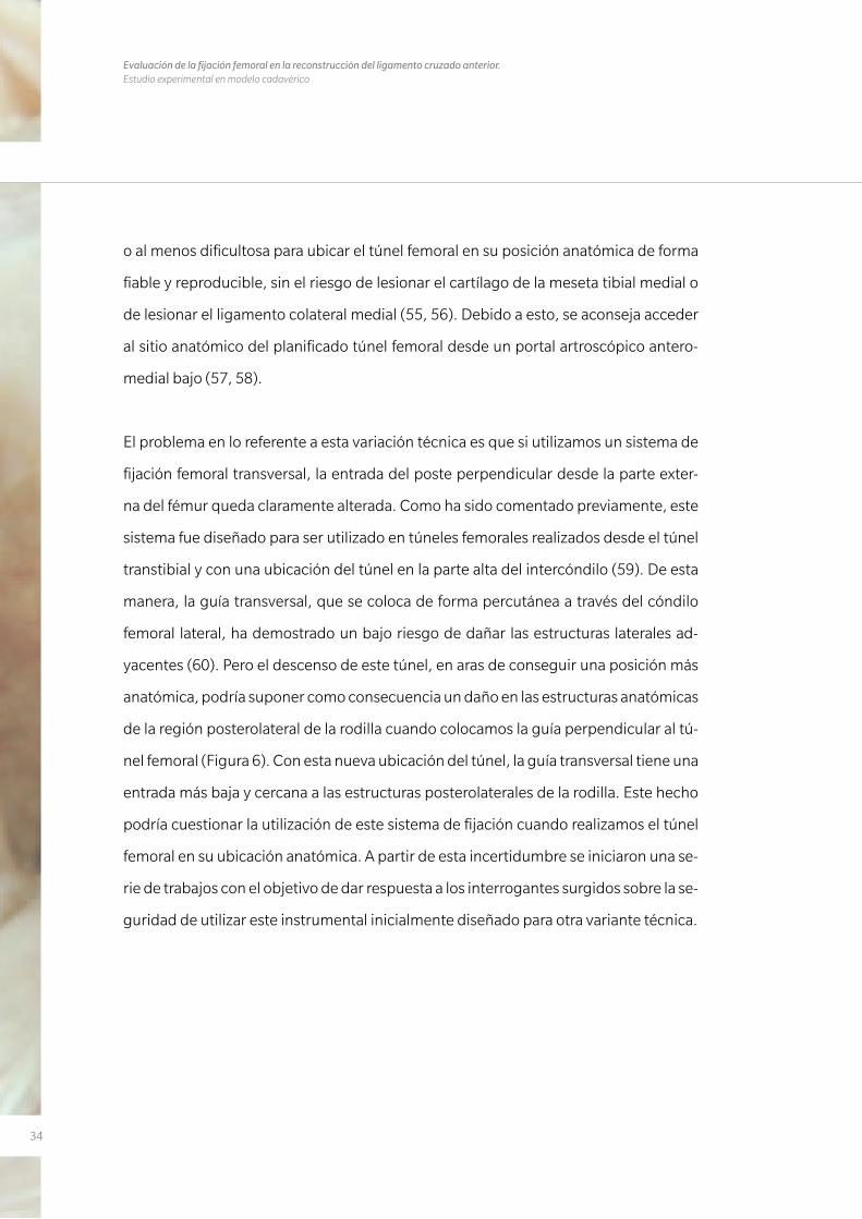
El problema en lo referente a esta variación técnica es que si utilizamos un sistema de
fijación femoral transversal, la entrada del poste perpendicular desde la parte exter-
na del fémur queda claramente alterada. Como ha sido comentado previamente, este
sistema fue diseñado para ser utilizado en túneles femorales realizados desde el túnel
transtibial y con una ubicación del túnel en la parte alta del intercóndilo (59). De esta
manera, la guía transversal, que se coloca de forma percutánea a través del cóndilo
femoral lateral, ha demostrado un bajo riesgo de dañar las estructuras laterales ad-
yacentes (60). Pero el descenso de este túnel, en aras de conseguir una posición más
anatómica, podría suponer como consecuencia un daño en las estructuras anatómicas
de la región posterolateral de la rodilla cuando colocamos la guía perpendicular al tú-
nel femoral (Figura 6). Con esta nueva ubicación del túnel, la guía transversal tiene una
entrada más baja y cercana a las estructuras posterolaterales de la rodilla. Este hecho
podría cuestionar la utilización de este sistema de fijación cuando realizamos el túnel
femoral en su ubicación anatómica. A partir de esta incertidumbre se iniciaron una se-
rie de trabajos con el objetivo de dar respuesta a los interrogantes surgidos sobre la se-
guridad de utilizar este instrumental inicialmente diseñado para otra variante técnica.
35
1.2.9 FUNDAMENTO DE LOS TRABAJOS
El primero de los trabajos incluidos en esta tesis (Anatomic single-bundle anterior cru-
ciate ligament reconstruction from the anteromedial portal: evaluation of transverse femo-
ral fixation in a cadaveric model) intenta dar respuesta a la idoneidad de un sistema de
fijación femoral transversal cuando realizamos este túnel siguiendo una técnica anató-
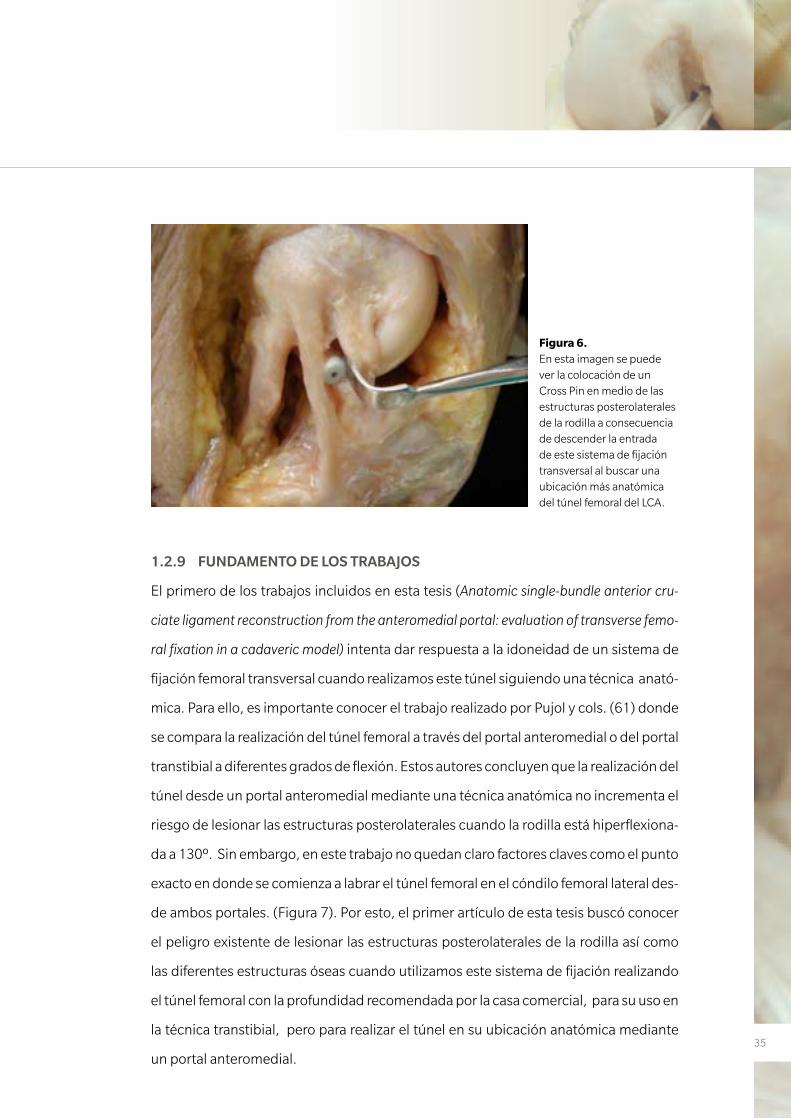
mica. Para ello, es importante conocer el trabajo realizado por Pujol y cols. (61) donde
se compara la realización del túnel femoral a través del portal anteromedial o del portal
transtibial a diferentes grados de flexión. Estos autores concluyen que la realización del
túnel desde un portal anteromedial mediante una técnica anatómica no incrementa el
riesgo de lesionar las estructuras posterolaterales cuando la rodilla está hiperflexiona-
da a 130º. Sin embargo, en este trabajo no quedan claro factores claves como el punto
exacto en donde se comienza a labrar el túnel femoral en el cóndilo femoral lateral des-
de ambos portales. (Figura 7). Por esto, el primer artículo de esta tesis buscó conocer
el peligro existente de lesionar las estructuras posterolaterales de la rodilla así como
las diferentes estructuras óseas cuando utilizamos este sistema de fijación realizando
el túnel femoral con la profundidad recomendada por la casa comercial, para su uso en
la técnica transtibial, pero para realizar el túnel en su ubicación anatómica mediante
un portal anteromedial.
Figura 6. En esta imagen se puede ver la colocación de un Cross Pin en medio de las estructuras posterolaterales de la rodilla a consecuencia de descender la entrada de este sistema de fijación transversal al buscar una ubicación más anatómica del túnel femoral del LCA.
36
Evaluación de la fijación femoral en la reconstrucción del ligamento cruzado anterior. Estudio experimental en modelo cadavérico
Con los resultados obtenidos en el primero de los trabajos y atendiendo a otros estu-
dios publicados, como el previamente comentado de Pujol y cols. (61), se diseñó un
segundo estudio (Effect of femoral tunnel length on the safety of anterior cruciate liga-
ment graft fixation using cross-pin technique: a cadaveric study) con la finalidad de cono-
cer si la variación en la longitud del túnel femoral podría variar el riesgo de lesionar las
estructuras posterolaterales de la rodilla utilizando el mismo sistema de fijación.
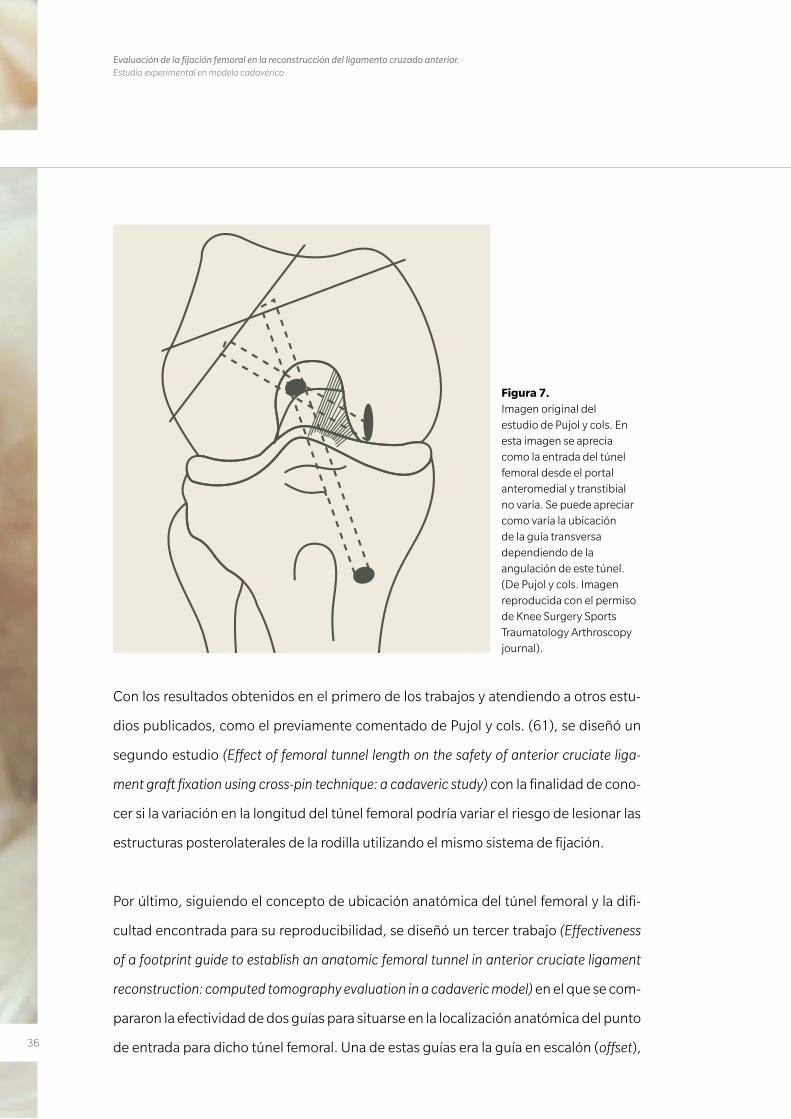
Por último, siguiendo el concepto de ubicación anatómica del túnel femoral y la difi-
cultad encontrada para su reproducibilidad, se diseñó un tercer trabajo (Effectiveness
of a footprint guide to establish an anatomic femoral tunnel in anterior cruciate ligament
reconstruction: computed tomography evaluation in a cadaveric model) en el que se com-
pararon la efectividad de dos guías para situarse en la localización anatómica del punto
de entrada para dicho túnel femoral. Una de estas guías era la guía en escalón (offset),
Figura 7. Imagen original del estudio de Pujol y cols. En esta imagen se aprecia como la entrada del túnel femoral desde el portal anteromedial y transtibial no varía. Se puede apreciar como varía la ubicación de la guía transversa dependiendo de la angulación de este túnel. (De Pujol y cols. Imagen reproducida con el permiso de Knee Surgery Sports Traumatology Arthroscopy journal).
37
tradicionalmente usada desde el portal transtibial, que toma como referencia la cor-
tical posterior del cóndilo femoral lateral. La otra guía era la guía BullsEye (ConMed
Linvatec, Largo, FL), diseñada específicamente para la realización de un túnel en la po-
sición anatómica desde el portal anteromedial (Figura 8).
Estos tres trabajos publicados en revistas de gran impacto dentro del mundo de la me-
dicina deportiva fueron realizados en modelos cadavéricos bajo técnicas artroscópicas
y su posterior estudio por disección de las estructuras posterolaterales de la rodilla. Se
estudiaron principalmente la importancia de la flexión de la rodilla, de la guía utilizada
para la realización de dicho túnel y de la longitud del túnel en el correcto emplaza-
miento del mismo para una mayor seguridad de estas estructuras anatómicas, todos
detalles técnicos de importancia capital en la reconstrucción quirúrgica del LCA.
Figura 8. Imágenes artroscópicas de las dos guías de túnel femoral evaluadas:
A) La guía de escalón (offset) toma como referencia la cortical posterior del cóndilo femoral externo.
B) La guía BullsEye, en cambio, se coloca directamente sobre la impronta del LCA.
38
Evaluación de la fijación femoral en la reconstrucción del ligamento cruzado anterior. Estudio experimental en modelo cadavérico
1.3 HIPÓTESIS DE TRABAJO
Hipótesis trabajo 1
La realización del túnel femoral siguiendo las recomendaciones indicadas por la técni-
ca quirúrgica del Cross-Pin (Stryker) en lo referente a la longitud del túnel femoral del
LCA, las cuales fueron descritas inicialmente para la realización del túnel desde un por-
tal transtibial, podrían poner en peligro las estructuras posterolaterales de la rodilla.
Hipótesis trabajo 2
La realización de un túnel femoral más largo de aquel recomendado por la técnica qui-
rúrgica de Cross-Pin prevendría el daño de las estructuras posterolaterales de la rodilla.
Hipótesis trabajo 3
La guía BullsEye (ConMed Linvatec), en comparación con la clásica guía de escalón fe-
moral proporcionaría una ubicación del túnel femoral más anatómica.
Adicionalmente, la segunda hipótesis de este trabajo fue que una mayor flexión de la
rodilla en el momento de la realización del túnel femoral permitiría obtener un túnel de
mayor longitud.

3939
M AT E R I A L Y M É TO D O S
2. MATERIAL Y MÉTODOS

40
Evaluación de la fijación femoral en la reconstrucción del ligamento cruzado anterior. Estudio experimental en modelo cadavérico
41
2. MATERIAL Y MÉTODOS
Trabajo nº1
Anatomic single-bundle anterior cruciate ligament reconstruction from the
anteromedial portal: evaluation of transverse femoral fixation in a cadaveric model.
En este primer estudio se evaluaron inicialmente 11 rodillas frescas con su extremidad
entera (6 izquierdas y 5 derechas). Una rodilla mostraba un importante estrechamien-
to del espacio intercondíleo durante la artroscopia por lo que fue excluida del estudio.
Las restantes 10 rodillas provenían de pacientes con una media de edad de 83,5 años
(rango 68-96). Estas rodillas fueron estudiadas estando montadas en un sistema es-
pecífico de soporte de material cadavérico (Extremity Holder; Saw-bones, Sweden).
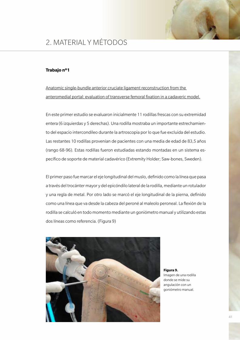
El primer paso fue marcar el eje longitudinal del muslo, definido como la línea que pasa
a través del trocánter mayor y del epicóndilo lateral de la rodilla, mediante un rotulador
y una regla de metal. Por otro lado se marcó el eje longitudinal de la pierna, definido
como una línea que va desde la cabeza del peroné al maleolo peroneal. La flexión de la
rodilla se calculó en todo momento mediante un goniómetro manual y utilizando estas
dos líneas como referencia. (Figura 9)
Figura 9. Imagen de una rodilla donde se mide su angulación con un goniómetro manual.
42
Evaluación de la fijación femoral en la reconstrucción del ligamento cruzado anterior. Estudio experimental en modelo cadavérico
Los tendones de los músculos gracilis y semitendinoso se obtuvieron mediante una in-
cisión longitudinal de unos 30 mm medial a la tuberosidad anterior de la tibia. Cada ten-
dón fue suturado en cada uno de sus extremos con hilos irreabsorbibles de forma tren-
zada. Al mismo tiempo se utilizó un alambre de 0.8 mm que se incluyó en el tendón con
la finalidad que la plastia fuera visible en el estudio radiológico posterior. El diámetro de
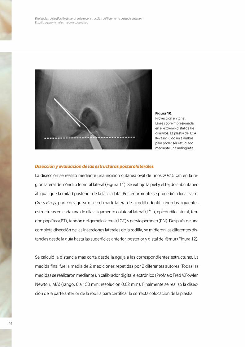
cada plastia, con el alambre incluido, fue medido en cada caso. (Figura 10).
El protocolo de experimentación fue el siguiente:
1º. Reconstrucción del LCA fijando la plastia a nivel del fémur mediante
el sistema Cross-Pin.
2º. Estudio radiológico para evaluar la ubicación del túnel
3º. Disección de la rodilla midiendo la distancia desde el Cross-Pin hasta
las estructuras que conforman la anatomía de la región posterolateral de la
rodilla.
Procedimiento artroscópico
El procedimiento se realizó con la rodilla a 90º de flexión. Se realizó un portal antero-
lateral alto utilizado como portal de visualización y se estableció un segundo portal
anteromedial bajo como portal de trabajo. Los referentes usados para establecer este
segundo portal fueron el extremo inferior de la rótula y un punto 1 cm medial al tendón
rotuliano.
El túnel tibial se realizó tomando como referencia intraarticular el centro de la huella
del LCA original. Dependiendo del diámetro de la plastia, se realizó un agujero de entre
7 y10 mm usando la instrumentación de la casa comercial (ACL System; Stryker).
El punto de partida para la realización del túnel tibial fue siempre 2 cm medial a la tube-
rosidad tibial anterior y el ángulo de inclinación en al plano sagital fue de 55º en todos
los casos. La desviación en el plano frontal, tomando como referencia un eje perpen-
43
dicular a la meseta tibial, fue de 20º. El túnel femoral se realizó con una flexión de rodi-
lla de 110º. La guía femoral tipo escalón utilizada dependía de la medida de la plastia
dejando 2 mm de margen en la pared posterior de manera que el túnel fuese colocado
en su posición más anatómica (62) y evitar el compromiso de esta pared posterior. El
túnel fue iniciado a nivel de las 10 en punto (rodilla derecha) y las 2 en punto (rodilla
izquierda), tomando como referencia el interior del intercóndilo en una esfera horaria
imaginaria. Este es conocido como el punto intermedio entre el haz anteromedial y
el posterolateral en la posición alta/baja (63). Siguiendo las recomendaciones de la
técnica Cross-Pin (Stryker), el túnel femoral fue labrado sobre un aguja guía a una pro-
fundidad de 30 mm mientras el tamaño del cóndilo lo permitiese. La guía transversal
fue introducida posteriormente de forma percutánea desde la parte lateral del cóndi-
lo femoral externo, con una inclinación ascendente de 20º en el plano horizontal. La
plastia de isquiotibiales fue entonces introducida y fijada en su lado femoral usando un
tornillo Biosteon (hidroxiapatita/Acido Poli-L-lactico) Cross-Pin (Bcp)(Stryker) de 6x40
o 6x50 mm. La fijación tibial se realizó mediante un tornillo metálico estándar de 7 o
10x25 mm.
Evaluación Radiológica
Se realizó una proyección radiológica de túnel (Rosenberg) a 30º de flexión a cada una
de las rodillas. De acuerdo con un método descrito recientemente, la orientación del
túnel femoral se calculó tomando como referencia la línea tangente a la parte distal de
los cóndilos femorales (64). Se realizó una superposición de un reloj mediante ordena-
dor a esta imagen radiológica de manera que las 12 en punto era el punto más alto del
intercóndilo. A partir de esta imagen obtuvimos el punto de entrada de las agujas que
se expresó en horas y en intervalos de cuartos de hora. (Figura 10).
44
Evaluación de la fijación femoral en la reconstrucción del ligamento cruzado anterior. Estudio experimental en modelo cadavérico
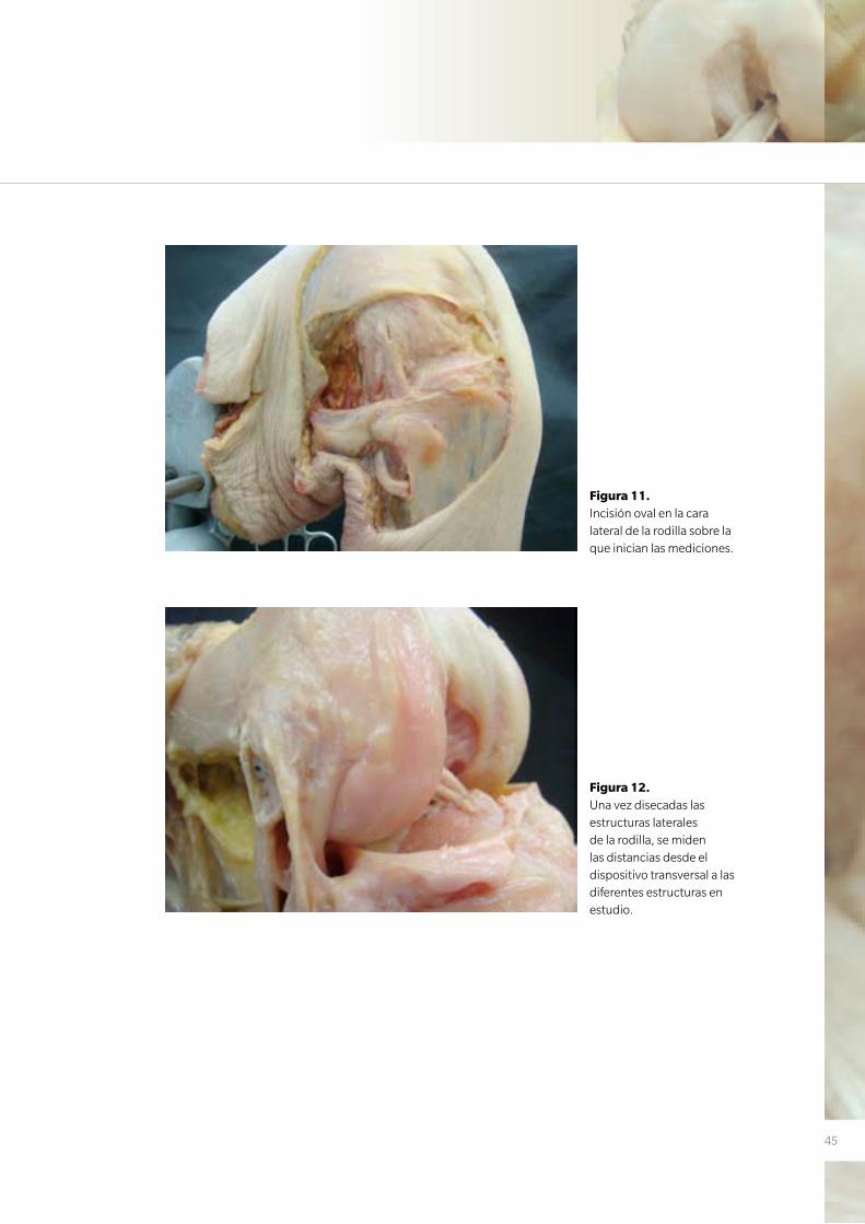
Disección y evaluación de las estructuras posterolaterales
La disección se realizó mediante una incisión cutánea oval de unos 20x15 cm en la re-
gión lateral del cóndilo femoral lateral (Figura 11). Se extrajo la piel y el tejido subcutaneo
al igual que la mitad posterior de la fascia lata. Posteriormente se procedió a localizar el
Cross-Pin y a partir de aquí se disecó la parte lateral de la rodilla identificando las siguientes
estructuras en cada una de ellas: ligamento colateral lateral (LCL), epicóndilo lateral, ten-
dón poplíteo (PT), tendón del gemelo lateral (LGT) y nervio peroneo (PN). Después de una
completa disección de las inserciones laterales de la rodilla, se midieron las diferentes dis-
tancias desde la guía hasta las superficies anterior, posterior y distal del fémur (Figura 12).
Se calculó la distancia más corta desde la aguja a las correspondientes estructuras. La
medida final fue la media de 2 mediciones repetidas por 2 diferentes autores. Todas las
medidas se realizaron mediante un calibrador digital electrónico (ProMax; Fred V.Fowler,
Newton, MA) (rango, 0 a 150 mm; resolución 0.02 mm). Finalmente se realizó la disec-
ción de la parte anterior de la rodilla para certificar la correcta colocación de la plastia.
Figura 10. Proyección en túnel. Línea sobreimpresionada en el extremo distal de los cóndilos. La plastia del LCA lleva incluido un alambre para poder ser estudiado mediante una radiografía.
45
Figura 11. Incisión oval en la cara lateral de la rodilla sobre la que inician las mediciones.
Figura 12. Una vez disecadas las estructuras laterales de la rodilla, se miden las distancias desde el dispositivo transversal a las diferentes estructuras en estudio.
46
Evaluación de la fijación femoral en la reconstrucción del ligamento cruzado anterior. Estudio experimental en modelo cadavérico
Trabajo nº2
Effect of femoral tunnel length on the safety of anterior cruciate ligament graft fixation
using cross-pin technique: a cadaveric study.
En el segundo de los estudios se realizó inicialmente un estudio piloto con 2 rodillas
frescas de cadáver humano. El estudio definitivo finalmente incluyó 22 rodillas de ca-
dáver de 14 varones y 8 mujeres cuyas edades estaban comprendidas entre 62 y 93
años (media, 76,6). Los especímenes se conservaron previamente al estudio a -18º C
y fueron descongelados a temperatura ambiente durante 24-36 horas antes de ser uti-
lizados. Como en el trabajo anterior, las rodillas fueron montadas en el mismo tipo de
soporte de rodilla y se marcó el eje longitudinal del muslo y la pierna.
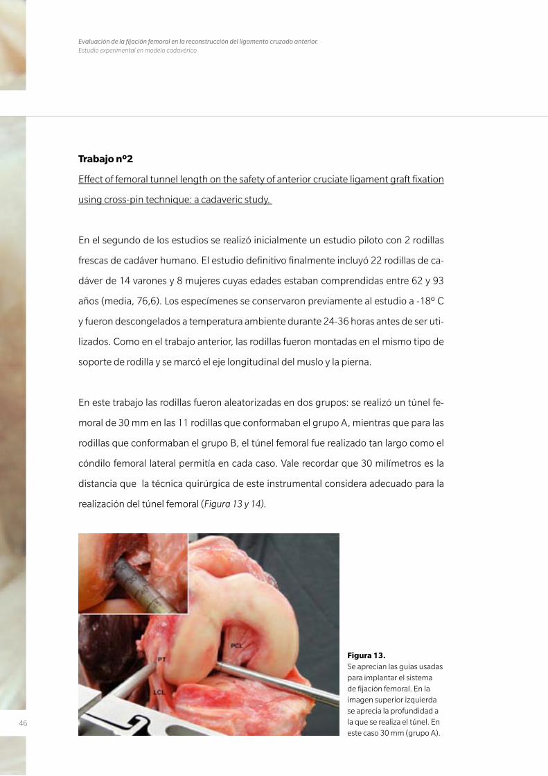
En este trabajo las rodillas fueron aleatorizadas en dos grupos: se realizó un túnel fe-
moral de 30 mm en las 11 rodillas que conformaban el grupo A, mientras que para las
rodillas que conformaban el grupo B, el túnel femoral fue realizado tan largo como el
cóndilo femoral lateral permitía en cada caso. Vale recordar que 30 milímetros es la
distancia que la técnica quirúrgica de este instrumental considera adecuado para la
realización del túnel femoral (Figura 13 y 14).
Figura 13. Se aprecian las guías usadas para implantar el sistema de fijación femoral. En la imagen superior izquierda se aprecia la profundidad a la que se realiza el túnel. En este caso 30 mm (grupo A).
47
Procedimiento artroscópico
El protocolo de actuación fue similar al del trabajo previo. Todas las rodillas colgaban
libremente a 90º de flexión. Se realizó un portal anteromedial alto como portal de vi-
sualización y un portal anteromedial bajo como portal de trabajo. Este segundo por-
tal más bajo se realizó tan inferior (cercano a la tibia) como fue posible con ayuda de
una aguja espinal y bajo visión directa evitando lesionar el cuerno anterior del menisco
medial. Además, el portal se sitúo tan medial como fue posible sin lesionar el cóndilo
femoral medial. El inicio del túnel femoral fue marcado en el centro del muñón del LCA.
Se realizó un túnel de 9 mm con una guía de broca convencional (ACL System, Stryker
Corp, Mahwah, New Jersey). El túnel tibial se realizó exactamente igual que en el traba-
jo precedente. Posteriormente se procedió a la realización del túnel femoral. Se utilizó
una guía de escalón de 7 mm para dejar 2,5 mm de pared posterior y así alcanzar la po-
sición anatómica en el plano profundo/superficial. La posición en el plano alto/bajo se
calculó siguiendo la esfera horaria. Se colocó cuidadosamente la guía en la posición de
10 en punto (rodilla derecha) y 2 en punto (rodilla izquierda) con la rodilla a 90º de fle-
xión, marcando en estos momentos el punto de entrada del túnel – reconocido como
el punto intermedio entre el haz anteromedial y posterolateral en el plano alto/bajo
(63). En este momento la rodilla se flexionó hasta los 110º para brocar el túnel femoral
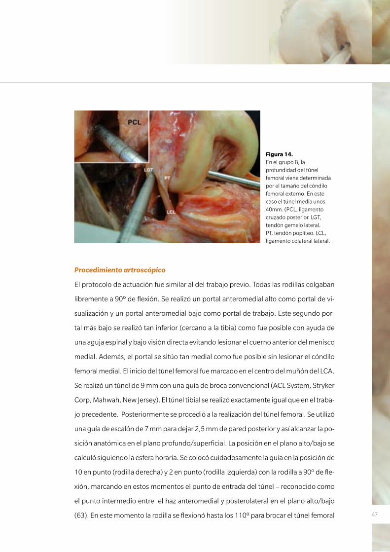
Figura 14. En el grupo B, la profundidad del túnel femoral viene determinada por el tamaño del cóndilo femoral externo. En este caso el túnel medía unos 40mm. (PCL, ligamento cruzado posterior. LGT, tendón gemelo lateral. PT, tendón poplíteo. LCL, ligamento colateral lateral.
48
Evaluación de la fijación femoral en la reconstrucción del ligamento cruzado anterior. Estudio experimental en modelo cadavérico
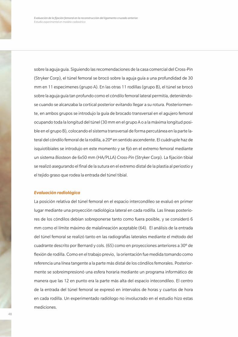
sobre la aguja guía. Siguiendo las recomendaciones de la casa comercial del Cross-Pin
(Stryker Corp), el túnel femoral se brocó sobre la aguja guía a una profundidad de 30
mm en 11 especimenes (grupo A). En las otras 11 rodillas (grupo B), el túnel se brocó
sobre la aguja guía tan profundo como el cóndilo femoral lateral permitía, deteniéndo-
se cuando se alcanzaba la cortical posterior evitando llegar a su rotura. Posteriormen-
te, en ambos grupos se introdujo la guía de brocado transversal en el agujero femoral
ocupando toda la longitud del túnel (30 mm en el grupo A o a la máxima longitud posi-
ble en el grupo B), colocando el sistema transversal de forma percutánea en la parte la-
teral del cóndilo femoral de la rodilla, a 20º en sentido ascendente. El cuádruple haz de
isquiotibiales se introdujo en este momento y se fijó en el extremo femoral mediante
un sistema Biosteon de 6x50 mm (HA/PLLA) Cross-Pin (Stryker Corp). La fijación tibial
se realizó asegurando el final de la sutura en el extremo distal de la plastia al periostio y
el tejido graso que rodea la entrada del túnel tibial.
Evaluación radiológica
La posición relativa del túnel femoral en el espacio intercondíleo se evaluó en primer
lugar mediante una proyección radiológica lateral en cada rodilla. Las líneas posterio-
res de los cóndilos debían sobreponerse tanto como fuera posible, y se consideró 6
mm como el límite máximo de malalineación aceptable (64). El análisis de la entrada
del túnel femoral se realizó tanto en las radiografías laterales mediante el método del
cuadrante descrito por Bernard y cols. (65) como en proyecciones anteriores a 30º de
flexión de rodilla. Como en el trabajo previo, la orientación fue medida tomando como
referencia una línea tangente a la parte más distal de los cóndilos femorales. Posterior-
mente se sobreimpresionó una esfera horaria mediante un programa informático de
manera que las 12 en punto era la parte más alta del espacio intecondíleo. El centro
de la entrada del túnel femoral se expresó en intervalos de horas y cuartos de hora
en cada rodilla. Un experimentado radiólogo no involucrado en el estudio hizo estas
mediciones.
49
Disección y evaluación de las estructuras posterolaterales
La disección se realizó de la misma manera que en el trabajo previo y se identificaron
las mismas estructuras además del Cross-Pin. La zona lateral del fémur donde el Cross-
Pin fue localizado fue clasificada dependiendo de su relación con el LCL. Aquellos ca-
sos donde el Cross-Pin fue colocado posterior al LCL se definió como zona de segu-
ridad; cuando el Cross-Pin atravesaba el LCL o era anterior al mismo se definió como
zona insegura (Figura 15). Después de resecar los tejidos blandos de la parte lateral
de la rodilla exceptuando el LCL y el PT, se evaluó la distancia desde la aguja guía a la
superficies posterior del fémur y del cartílago articular (CA).
A continuación se calcularon las distancias más cortas desde la aguja guía a las diferen-
tes estructuras estudiadas mediante el mismo calibre electrónico utilizado en el estu-
dio previo. Por último, se realizó la disección de las estructuras anteriores de la rodilla
para poder certificar la correcta ubicación de la plastia.
Figura 15. En esta imagen de la cara lateral de la rodilla se ve en diferentes tonalidades la región definida como segura (Verde) y no segura (Rojo).
50
Evaluación de la fijación femoral en la reconstrucción del ligamento cruzado anterior. Estudio experimental en modelo cadavérico
Análisis estadístico
Las variables categóricas se presentaron como porcentajes y frecuencias. Se utilizaron
tanto el Test del Chi-Cuadrado de Pearson como el Test exacto de Fisher para comparar
estas variables entre grupos. Para cada variable continua se calculó la media y desvia-
ción estándar así como la mediana y los cuartiles. Debido al pequeño número de la
muestra y la dificultad en determinar si las variables se ajustaban a una distribución
normal, se utilizó el test de Mann-Whitney para comparar las medidas en ambos gru-
pos. Estas variables continuas se presentaron como una mediana. El análisis estadísti-
co se realizó usando el SPSS 15 (SPSS Inc, Chicago, Illinois). La diferencia se consideró
significativa al nivel de 0,05.
51
Trabajo nº3
Effectiveness of a footprint guide to establish an anatomic femoral tunnel in anterior
cruciate ligament reconstruction: computed tomograpny evaluation in a cadaveric
model.
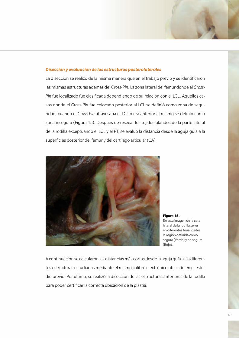
En este último trabajo se utilizaron 14 rodillas pareadas (pares del mismo donante)
frescas de donantes voluntarios de extremidades inferiores completas. Había 4 donan-
tes varones y 3 mujeres, cuyas edades variaban desde 54 a 85 años (media, 76 años).
Los especimenes se conservaron, descongelaron, montaron y marcaron del mismo
modo que se había realizado en los trabajos previos.
A cada una de las 2 rodillas del mismo donante se les asignó para cada uno de dos dife-
rentes grupos: Grupo A, con un túnel realizado mediante una guía de escalón estándar
de 5 mm, y Grupo B, con un túnel realizado con la ayuda de la recientemente diseñada
guía BullsEye. El uso de rodillas pareadas se hizo para minimizar las diferencias anató-
micas entre especimenes (Figura 16).
Figura 16. En la izquierda se observa la guía escalón que toma como referencia la cortical posterior del cón-dilo femoral externo para introducir la aguja guía para la realización del túnel femoral. En la derecha se aprecia la guía BullsEye, que se coloca directamente sobre la huella del LCA.
52
Evaluación de la fijación femoral en la reconstrucción del ligamento cruzado anterior. Estudio experimental en modelo cadavérico
Procedimiento artroscópico
El procedimiento artroscópico se realizó de manera similar a los trabajos previos pero
con algunas variaciones. Las rodillas colgaban libremente a 90º de flexión y sólo cuan-
do había que iniciar el túnel femoral la flexión se incrementaba a 110º o 130º. Como
en los otros trabajos, se realizaron 2 portales anteromediales; uno alto como portal
de visualización y otro más bajo (parapatelar) que nos servía para visualizar mejor la
pared medial del cóndilo femoral externo así como portal de trabajo. Como ya hemos
comentado previamente, este portal se intenta situar lo más medial posible para no
dañar el cóndilo femoral medial y tan distal como es posible sin dañar el cuerno ante-
rior del menisco interno.
En el grupo A, la colocación del túnel femoral se realizó con la ayuda de una guía de esca-
lón de 5 mm. La ubicación del mismo se situó a las 10 en punto en las rodillas derechas y
a las 2 en punto en las rodillas izquierdas. En el grupo B, el túnel femoral se localizó con la
ayuda de la guía de BullsEye. Su diseño abierto permite una fácil visualización de la inser-
ción femoral original del LCA. El centro del túnel se situó en el punto intermedio entre el
haz AM y el PL o en el centro de la cresta bifurcada (Figura 17), si esta se lograba apreciar
claramente. En cada grupo el procedimiento fue el siguiente (Figura 18):
1. Se introdujo una aguja de Kirshner de 2.5 mm a 110º de flexión atravesando todo
el espesor del cóndilo femoral lateral y sobre ella se brocó un túnel de 5 mm
2. Se colocó una aguja de Kirshner similar en el mismo punto de partida pero con la
rodilla flexionada a 130º para posteriormente ampliar el túnel con una broca de
5 mm
3. Los primeros 10-15 mm del punto de entrada del túnel femoral se ampliaron con
una broca de 8 mm. Este gesto se realizó para simular una situación clínica normal
de la reconstrucción anatómica del LCA con un sólo fascículo al realizar la ex-
ploración con la tomografía computada en 3 dimensiones (TC-3D). Este gesto se
realizó también a 130º (Figura 19).
53
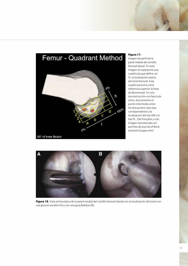
Figura 17. Imagen de perfil de la parte medial del cóndilo femoral lateral. En esta imagen se superpone una cuadricula que define, en %, la localización exacta del túnel femoral. Esta cuadrícula toma como referencia superior la línea de Blumensaat. En una reconstrucción con fascículo único, buscaríamos el punto intermedio entre los dos puntos rojos que corresponderían a la localización del haz AM y el haz PL. (De Forsythe y cols. Imagen reproducida con permiso de Journal of Bone and Joint Surgery Am)
Figura 18. Vista artroscópica de la pared medial del cóndilo femoral lateral con la localización del túnel con una guía en escalón (A) y con una guía BullsEye (B).
54
Evaluación de la fijación femoral en la reconstrucción del ligamento cruzado anterior. Estudio experimental en modelo cadavérico
Estudio con TC
Para la realización del TC, todas las rodillas se colocaron en extensión completa obte-
niéndose múltiples planos de alta resolución en 3D de la ubicación de los túneles. Para
ello se utilizó un aparato modelo CT Scan Toshiba Aquilon TSX-101A (Toshiba Medical
Systems, Toshigi-Ken, Japan) (Figura 20). Posteriormente, y con la ayuda de un progra-
ma informático, se procesaron las imágenes, EFilm Workstation 2.1.2 (Merge Health-
care, Hartland, WI). Un radiólogo, experto en el área musculoesquelética, realizó todas
las mediciones 2 veces y se obtuvo la media de estas. Los parámetros estudiados fue-
ron los siguientes:
• La distancia mínima desde el túnel de 8 mm al margen posterior del cartílago ar-
ticular. Esta distancia se denominó la distancia al margen del cartílago proximal
(DPCM). Esta referencia toma como modelo los estudios de Colombet y cols. (62) y
Baskedis y cols. (66).
• La distancia más corta desde el centro del túnel de 8 mm hasta el margen anteroin-
ferior del cartílago articular (hacia abajo en el intercóndilo). Esta medida se deno-
minó la distancia al margen del cartílago distal (DDCM) y también fue tomada de
los artículos previamente citados (62, 66) (Figura 21).
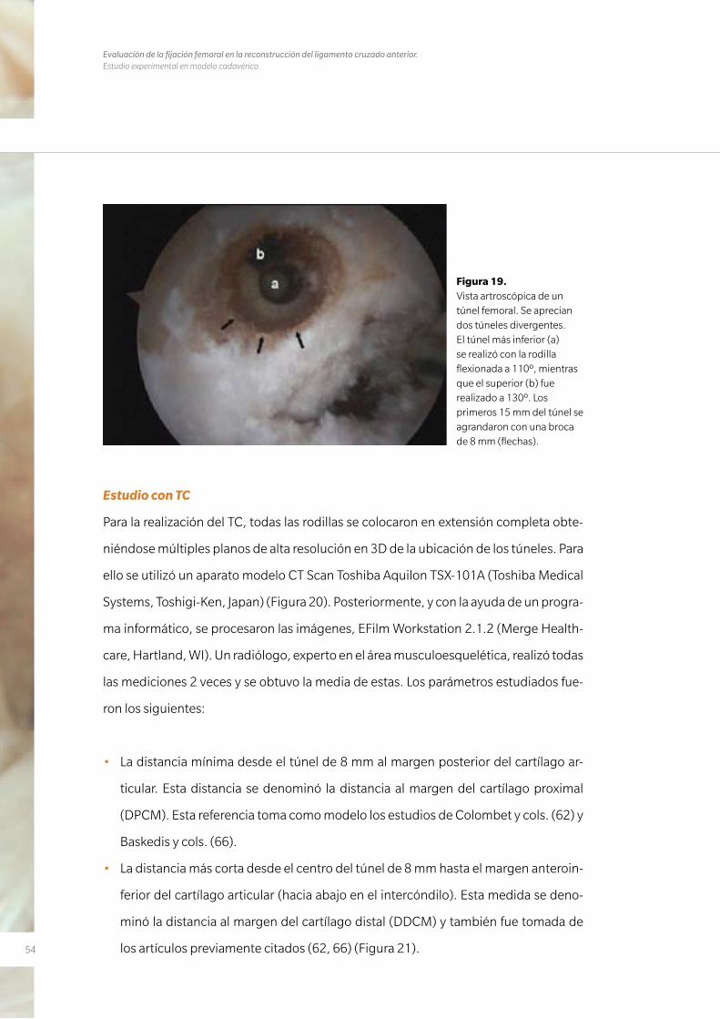
Figura 19. Vista artroscópica de un túnel femoral. Se aprecian dos túneles divergentes. El túnel más inferior (a) se realizó con la rodilla flexionada a 110º, mientras que el superior (b) fue realizado a 130º. Los primeros 15 mm del túnel se agrandaron con una broca de 8 mm (flechas).
55
• La posición del túnel se calculó con el método del cuadrante descrito por Forsythe
y cols. (67). En una visión medial real del fémur con la rodilla flexionada a 90º, se
sobreimpresionó una cuadrícula de 4x4 a las imágenes 3D del TC en la pared me-
dial del cóndilo lateral. Siguiendo las recomendaciones de Forsythe y cols., el límite
anterior del techo del intercóndilo femoral se consideró la referencia a la hora de
alinear la cuadrícula (Figura 17).
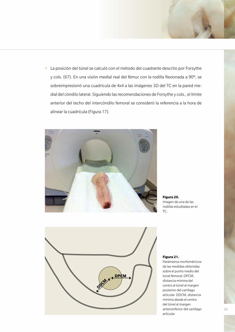
Figura 20. Imagen de una de las rodillas estudiadas en el TC.
Figura 21. Parámetros morfométricos de las medidas obtenidas sobre el punto medio del túnel femoral; DPCM, distancia mínima del centro al túnel al margen posterior del cartílago articular. DDCM, distancia mínima desde el centro del túnel al margen anteroinferior del cartílago articular.
DPCM
DDCM
56
Evaluación de la fijación femoral en la reconstrucción del ligamento cruzado anterior. Estudio experimental en modelo cadavérico
Mientras que estas tres medidas se calcularon sobre las reconstrucciones TC-3D, otras
lo fueron de imágenes seleccionadas que eran co-planares con el túnel para así conse-
guir una medida directa desde la apertura intraarticular a la extraarticular:
• Longitud de los dos túneles en cada rodilla; tanto la longitud del túnel realizado a
110º de flexión en el grupo A o B como la longitud del túnel realizado a 130º de fle-
xión en ambos grupos. Debido a que el cóndilo femoral lateral tiene una morfología
redondeada y el túnel no se realiza de forma ortogonal, la longitud de la medida
puede variar dependiendo de si el borde anterior o posterior del túnel se usa como
referencia. Por esto la longitud del túnel se midió en el centro del túnel. Los túneles
más cortos de 25 mm, la mínima medida recomendada para un túnel, fueron desta-
cados. (68-70).
• Ángulo de divergencia (TDA) entre el túnel realizado a 110º de flexión y el realizado
a 130º de flexión.
• Distancia mínima entre ambos túneles en el punto de salida en la cortical lateral del
cóndilo femoral lateral mediante imágenes coplanares.
• Se reportó el compromiso de la pared posterior como cualquier discontinuidad en
la cortical posterior del túnel evidenciada en cualquier corte de TC.
Análisis estadístico
Las variables categóricas se presentaron como porcentajes y frecuencias. Para cada
variable continua, se calculó la media y desviación estándar así como la mediana y los
cuartiles. Debido al bajo número de la muestra y la dificultada para determinar si las va-
riables estaban o no ajustadas a una distribución normal, se utilizó el test no paramétri-
co de Wilcoxon para comparar las medidas en ambos grupos. Las variables continuas
se presentaron como medianas. El análisis estadístico se realizó con el software SPSS v
12 (SPSS, Chicago, IL). Se estableció 0,05 como el límite de la significación estadística.

5757
R E S U LTA D O S
3. RESULTADOS

58
Evaluación de la fijación femoral en la reconstrucción del ligamento cruzado anterior. Estudio experimental en modelo cadavérico
59
3. RESULTADOS
Trabajo nº1
Anatomic single-bundle anterior cruciate ligament reconstruction from the
anteromedial portal: evaluation of transverse femoral fixation in a cadaveric model.
En 8 casos se obtuvo un túnel femoral de una profundidad de 30 mm. En los otros 2
casos la longitud del túnel femoral fue de 25 y 23 mm debido al pequeño tamaño de
los cóndilos. En estos casos se perforó la cortical posterolateral del fémur. En el últi-
mo de estos 2 casos (caso 8), se observó un moderado estrechamiento del espacio
intercondíleo aunque no se realizó una intercondiloplastia ya que la impresión fue que
este moderado estrechamiento intercondíleo no influenciaría en la ubicación del túnel
(Tabla 1).
Evaluación radiológica
El ángulo medio de la orientación del túnel femoral con respecto a la referencia de la lí-
nea biepicondílea fue de 52,1º (rango 40º a 60º). Si tomamos como referencia la esfera
horaria, la posición media del túnel era a las 10 en punto (rango 9:15, 10:30) (Figura 10).
LCL y Epicóndilo Lateral
La posición del dispositivo transversal con respecto al LCL variaba de un especimen a
otro. En 8 casos este dispositivo estaba situado posterior al LCL (rango, 0 a 7,96 mm,
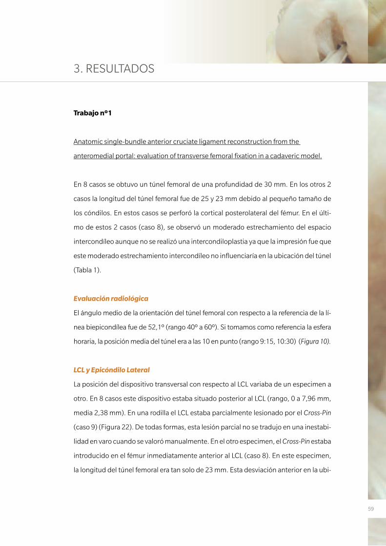
media 2,38 mm). En una rodilla el LCL estaba parcialmente lesionado por el Cross-Pin
(caso 9) (Figura 22). De todas formas, esta lesión parcial no se tradujo en una inestabi-
lidad en varo cuando se valoró manualmente. En el otro especimen, el Cross-Pin estaba
introducido en el fémur inmediatamente anterior al LCL (caso 8). En este especimen,
la longitud del túnel femoral era tan solo de 23 mm. Esta desviación anterior en la ubi-
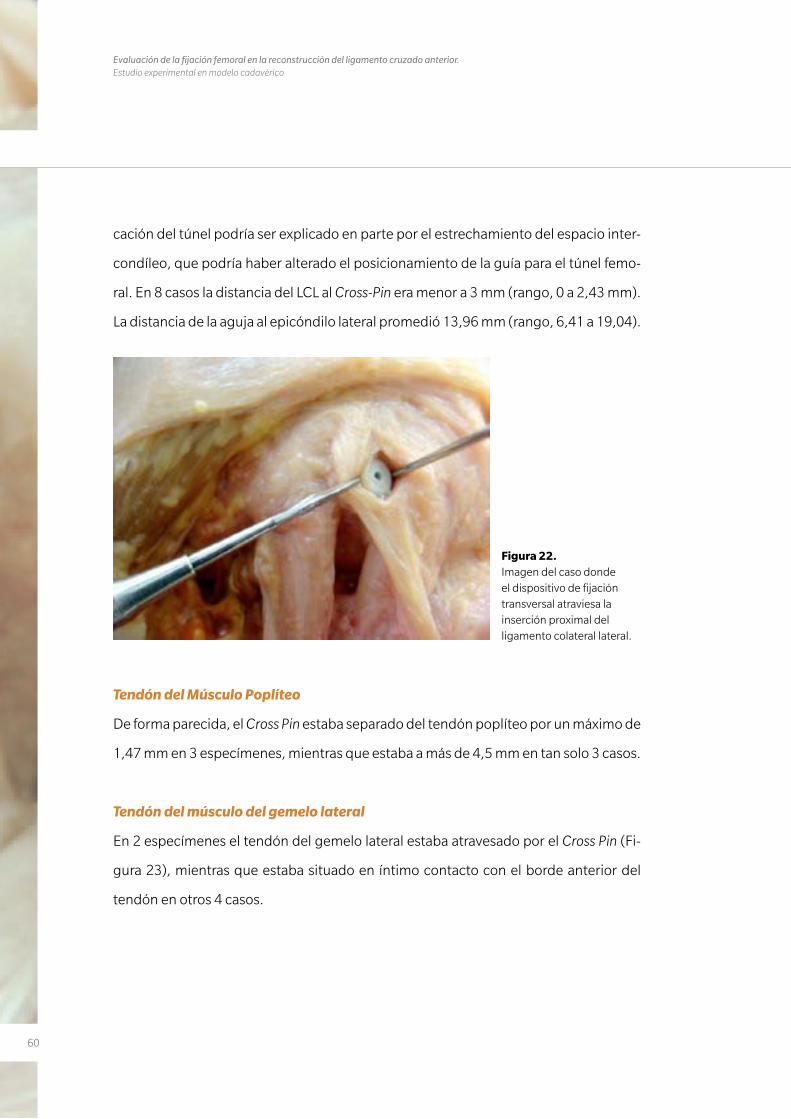
60
Evaluación de la fijación femoral en la reconstrucción del ligamento cruzado anterior. Estudio experimental en modelo cadavérico
cación del túnel podría ser explicado en parte por el estrechamiento del espacio inter-
condíleo, que podría haber alterado el posicionamiento de la guía para el túnel femo-
ral. En 8 casos la distancia del LCL al Cross-Pin era menor a 3 mm (rango, 0 a 2,43 mm).
La distancia de la aguja al epicóndilo lateral promedió 13,96 mm (rango, 6,41 a 19,04).
Figura 22. Imagen del caso donde el dispositivo de fijación transversal atraviesa la inserción proximal del ligamento colateral lateral.
Tendón del Músculo Poplíteo
De forma parecida, el Cross Pin estaba separado del tendón poplíteo por un máximo de
1,47 mm en 3 especímenes, mientras que estaba a más de 4,5 mm en tan solo 3 casos.
Tendón del músculo del gemelo lateral
En 2 especímenes el tendón del gemelo lateral estaba atravesado por el Cross Pin (Fi-
gura 23), mientras que estaba situado en íntimo contacto con el borde anterior del
tendón en otros 4 casos.
61
Nervio Peroneo
La distancia mínima desde el Cross Pin al nervio peroneo fue de 23,89 mm (media,
38,48mm).
Corticales Femorales
La distancia media a la cortical anterior del fémur fue de 27,2mm (rango, 17,45 a 35,4
mm). La parte más distal del fémur distaba de media al Cross Pin 8,17 mm (rango, 4,08
a 15,8 mm). En un caso, el Cross Pin se dirigió directo a la cortical posterior, con su mi-
tad posterior situada en la fosa poplítea. En 7 casos el Cross-Pin estaba a 1,52 mm de
esta superficie posterior (media, 1,35 mm). En los 2 casos restantes, donde el Cross Pin
estaba situado anteriormente (caso 8) o en el medio del LCL (caso 9), la distancia a la
cortical posterior era de 14,06 y 9,5 mm respectivamente.
Bajo evaluación directa del túnel femoral, se confirmó una distancia mínima de 2 mm
del Cross Pin a la pared posterior en todas las rodillas.
Figura 23. Imagen donde se aprecia como el dispositivo transversal atraviesa el tendón del gemelo lateral.
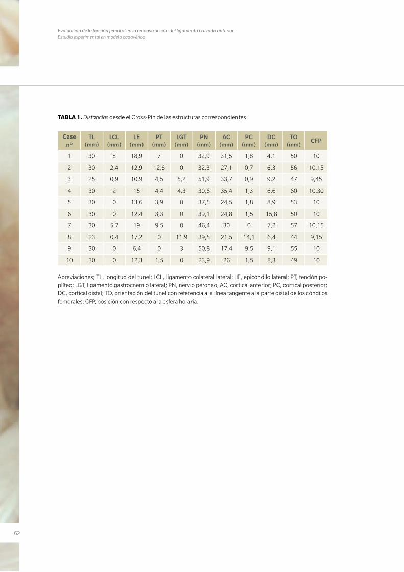
62
Evaluación de la fijación femoral en la reconstrucción del ligamento cruzado anterior. Estudio experimental en modelo cadavérico
TABLA 1. Distancias desde el Cross-Pin de las estructuras correspondientes
Case nº
TL (mm)
LCL (mm)
LE (mm)
PT (mm)
LGT (mm)
PN (mm)
AC (mm)
PC (mm)
DC (mm)
TO (mm)
CFP
1 30 8 18,9 7 0 32,9 31,5 1,8 4,1 50 10
2 30 2,4 12,9 12,6 0 32,3 27,1 0,7 6,3 56 10,15
3 25 0,9 10,9 4,5 5,2 51,9 33,7 0,9 9,2 47 9,45
4 30 2 15 4,4 4,3 30,6 35,4 1,3 6,6 60 10,30
5 30 0 13,6 3,9 0 37,5 24,5 1,8 8,9 53 10
6 30 0 12,4 3,3 0 39,1 24,8 1,5 15,8 50 10
7 30 5,7 19 9,5 0 46,4 30 0 7,2 57 10,15
8 23 0,4 17,2 0 11,9 39,5 21,5 14,1 6,4 44 9,15
9 30 0 6,4 0 3 50,8 17,4 9,5 9,1 55 10
10 30 0 12,3 1,5 0 23,9 26 1,5 8,3 49 10
Abreviaciones; TL, longitud del túnel; LCL, ligamento colateral lateral; LE, epicóndilo lateral; PT, tendón po-plíteo; LGT, ligamento gastrocnemio lateral; PN, nervio peroneo; AC, cortical anterior; PC, cortical posterior; DC, cortical distal; TO, orientación del túnel con referencia a la línea tangente a la parte distal de los cóndilos femorales; CFP, posición con respecto a la esfera horaria.
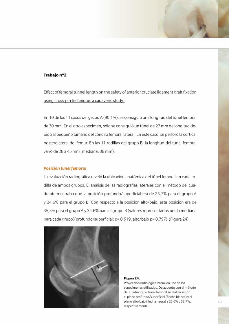
63
Trabajo nº2
Effect of femoral tunnel length on the safety of anterior cruciate ligament graft fixation
using cross-pin technique: a cadaveric study.
En 10 de los 11 casos del grupo A (90.1%), se consiguió una longitud del túnel femoral
de 30 mm. En el otro especimen, sólo se consiguió un túnel de 27 mm de longitud de-
bido al pequeño tamaño del cóndilo femoral lateral. En este caso, se perforó la cortical
posterolateral del fémur. En las 11 rodillas del grupo B, la longitud del túnel femoral
varió de 28 a 45 mm (mediana, 38 mm).
Posición túnel femoral
La evaluación radiográfica reveló la ubicación anatómica del túnel femoral en cada ro-
dilla de ambos grupos. El análisis de las radiografías laterales con el método del cua-
drante mostraba que la posición profundo/superficial era de 25,7% para el grupo A
y 34,6% para el grupo B. Con respecto a la posición alto/bajo, esta posición era de
35,3% para el grupo A y 34.6% para el grupo B (valores representados por la mediana
para cada grupo)(profundo/superficial; p= 0,519, alto/bajo p= 0,797) (Figura 24).
Figura 24. Proyección radiológica lateral en uno de los especimenes utilizados. De acuerdo con el método del cuadrante, el túnel femoral se realizó según el plano profundo/superficial (flecha blanca) y el plano alto/bajo (flecha negra) a 25,6% y 32,7%, respectivamente.
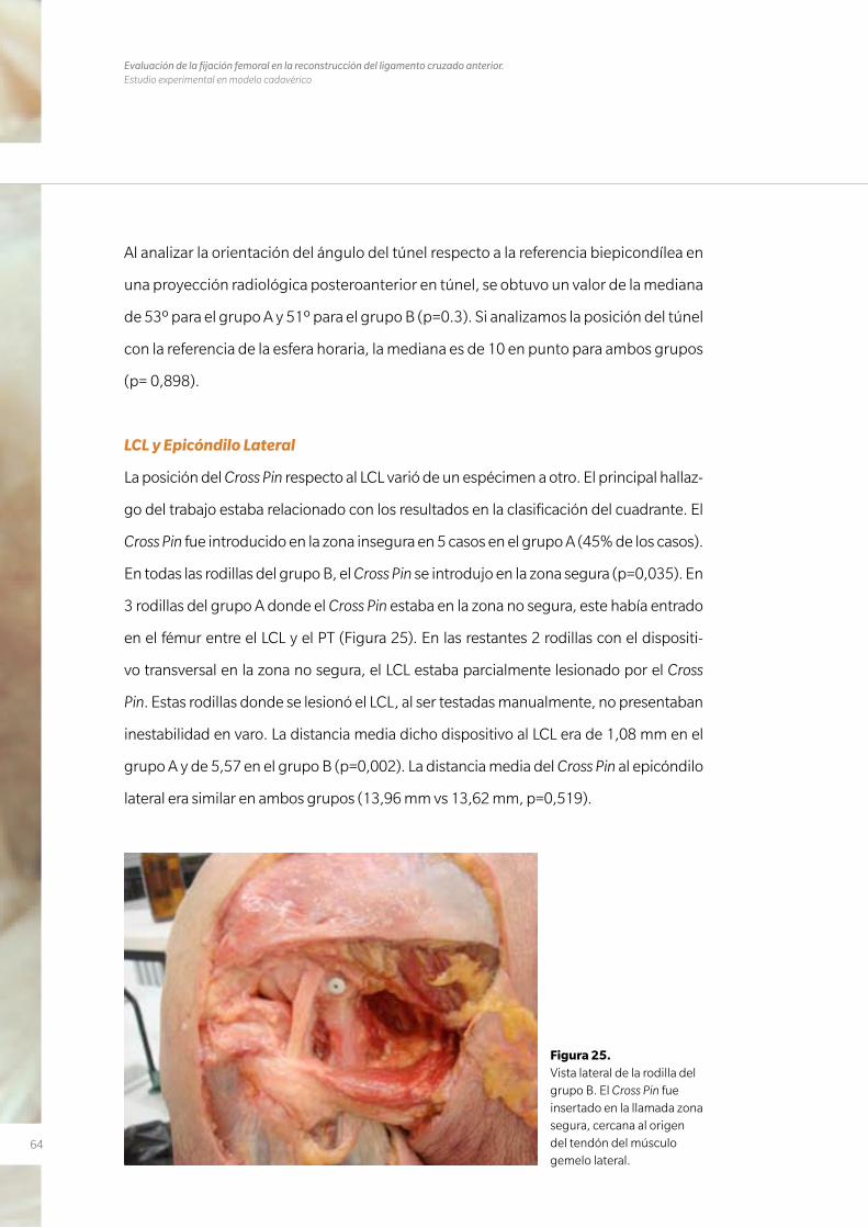
64
Evaluación de la fijación femoral en la reconstrucción del ligamento cruzado anterior. Estudio experimental en modelo cadavérico
Al analizar la orientación del ángulo del túnel respecto a la referencia biepicondílea en
una proyección radiológica posteroanterior en túnel, se obtuvo un valor de la mediana
de 53º para el grupo A y 51º para el grupo B (p=0.3). Si analizamos la posición del túnel
con la referencia de la esfera horaria, la mediana es de 10 en punto para ambos grupos
(p= 0,898).
LCL y Epicóndilo Lateral
La posición del Cross Pin respecto al LCL varió de un espécimen a otro. El principal hallaz-
go del trabajo estaba relacionado con los resultados en la clasificación del cuadrante. El
Cross Pin fue introducido en la zona insegura en 5 casos en el grupo A (45% de los casos).
En todas las rodillas del grupo B, el Cross Pin se introdujo en la zona segura (p=0,035). En
3 rodillas del grupo A donde el Cross Pin estaba en la zona no segura, este había entrado
en el fémur entre el LCL y el PT (Figura 25). En las restantes 2 rodillas con el dispositi-
vo transversal en la zona no segura, el LCL estaba parcialmente lesionado por el Cross
Pin. Estas rodillas donde se lesionó el LCL, al ser testadas manualmente, no presentaban
inestabilidad en varo. La distancia media dicho dispositivo al LCL era de 1,08 mm en el
grupo A y de 5,57 en el grupo B (p=0,002). La distancia media del Cross Pin al epicóndilo
lateral era similar en ambos grupos (13,96 mm vs 13,62 mm, p=0,519).
Figura 25. Vista lateral de la rodilla del grupo B. El Cross Pin fue insertado en la llamada zona segura, cercana al origen del tendón del músculo gemelo lateral.
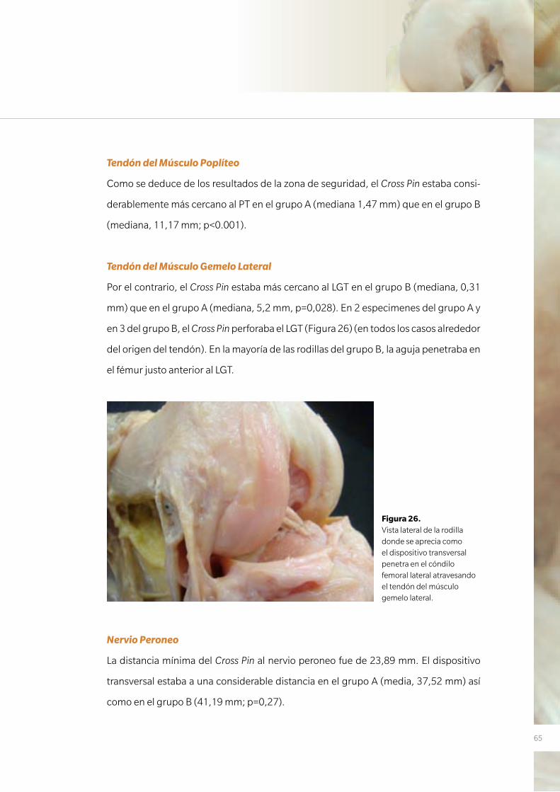
65
Tendón del Músculo Poplíteo
Como se deduce de los resultados de la zona de seguridad, el Cross Pin estaba consi-
derablemente más cercano al PT en el grupo A (mediana 1,47 mm) que en el grupo B
(mediana, 11,17 mm; p<0.001).
Tendón del Músculo Gemelo Lateral
Por el contrario, el Cross Pin estaba más cercano al LGT en el grupo B (mediana, 0,31
mm) que en el grupo A (mediana, 5,2 mm, p=0,028). En 2 especimenes del grupo A y
en 3 del grupo B, el Cross Pin perforaba el LGT (Figura 26) (en todos los casos alrededor
del origen del tendón). En la mayoría de las rodillas del grupo B, la aguja penetraba en
el fémur justo anterior al LGT.
Nervio Peroneo
La distancia mínima del Cross Pin al nervio peroneo fue de 23,89 mm. El dispositivo
transversal estaba a una considerable distancia en el grupo A (media, 37,52 mm) así
como en el grupo B (41,19 mm; p=0,27).
Figura 26. Vista lateral de la rodilla donde se aprecia como el dispositivo transversal penetra en el cóndilo femoral lateral atravesando el tendón del músculo gemelo lateral.
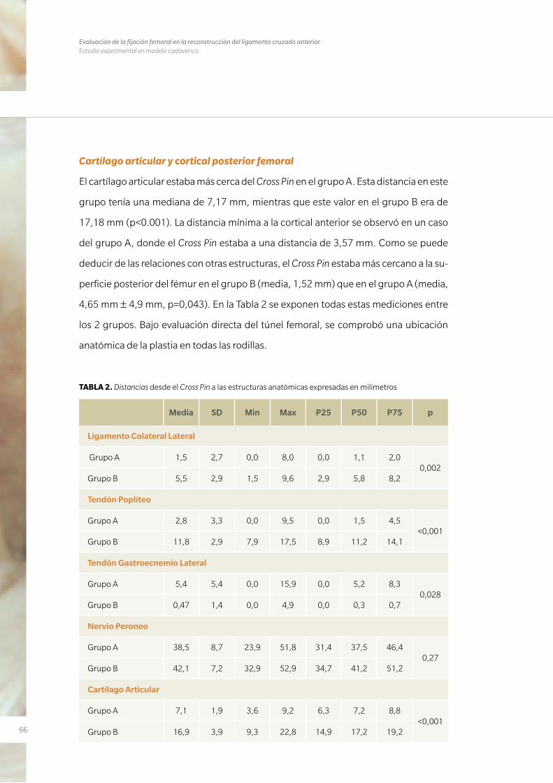
66
Evaluación de la fijación femoral en la reconstrucción del ligamento cruzado anterior. Estudio experimental en modelo cadavérico
Cartílago articular y cortical posterior femoral
El cartílago articular estaba más cerca del Cross Pin en el grupo A. Esta distancia en este
grupo tenía una mediana de 7,17 mm, mientras que este valor en el grupo B era de
17,18 mm (p<0.001). La distancia mínima a la cortical anterior se observó en un caso
del grupo A, donde el Cross Pin estaba a una distancia de 3,57 mm. Como se puede
deducir de las relaciones con otras estructuras, el Cross Pin estaba más cercano a la su-
perficie posterior del fémur en el grupo B (media, 1,52 mm) que en el grupo A (media,
4,65 mm ± 4,9 mm, p=0,043). En la Tabla 2 se exponen todas estas mediciones entre
los 2 grupos. Bajo evaluación directa del túnel femoral, se comprobó una ubicación
anatómica de la plastia en todas las rodillas.
Media SD Min Max P25 P50 P75 p
Ligamento Colateral Lateral
Grupo A 1,5 2,7 0,0 8,0 0,0 1,1 2,00,002
Grupo B 5,5 2,9 1,5 9,6 2,9 5,8 8,2
Tendón Poplíteo
Grupo A 2,8 3,3 0,0 9,5 0,0 1,5 4,5<0,001
Grupo B 11,8 2,9 7,9 17,5 8,9 11,2 14,1
Tendón Gastroecnemio Lateral
Grupo A 5,4 5,4 0,0 15,9 0,0 5,2 8,30,028
Grupo B 0,47 1,4 0,0 4,9 0,0 0,3 0,7
Nervio Peroneo
Grupo A 38,5 8,7 23,9 51,8 31,4 37,5 46,40,27
Grupo B 42,1 7,2 32,9 52,9 34,7 41,2 51,2
Cartílago Articular
Grupo A 7,1 1,9 3,6 9,2 6,3 7,2 8,8<0,001
Grupo B 16,9 3,9 9,3 22,8 14,9 17,2 19,2
TABLA 2. Distancias desde el Cross Pin a las estructuras anatómicas expresadas en milímetros
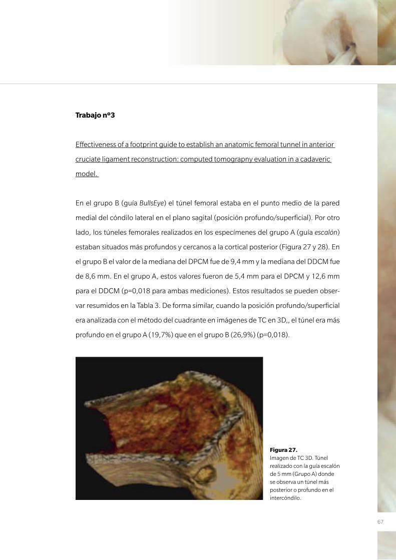
67
Trabajo nº3
Effectiveness of a footprint guide to establish an anatomic femoral tunnel in anterior
cruciate ligament reconstruction: computed tomograpny evaluation in a cadaveric
model.
En el grupo B (guía BullsEye) el túnel femoral estaba en el punto medio de la pared
medial del cóndilo lateral en el plano sagital (posición profundo/superficial). Por otro
lado, los túneles femorales realizados en los especímenes del grupo A (guía escalón)
estaban situados más profundos y cercanos a la cortical posterior (Figura 27 y 28). En
el grupo B el valor de la mediana del DPCM fue de 9,4 mm y la mediana del DDCM fue
de 8,6 mm. En el grupo A, estos valores fueron de 5,4 mm para el DPCM y 12,6 mm
para el DDCM (p=0,018 para ambas mediciones). Estos resultados se pueden obser-
var resumidos en la Tabla 3. De forma similar, cuando la posición profundo/superficial
era analizada con el método del cuadrante en imágenes de TC en 3D,, el túnel era más
profundo en el grupo A (19,7%) que en el grupo B (26,9%) (p=0,018).
Figura 27. Imagen de TC 3D. Túnel realizado con la guía escalón de 5 mm (Grupo A) donde se observa un túnel más posterior o profundo en el intercóndilo.
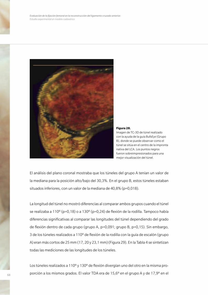
68
Evaluación de la fijación femoral en la reconstrucción del ligamento cruzado anterior. Estudio experimental en modelo cadavérico
El análisis del plano coronal mostraba que los túneles del grupo A tenían un valor de
la mediana para la posición alto/bajo del 30,3%. En el grupo B, estos túneles estaban
situados inferiores, con un valor de la mediana de 40,8% (p=0,018).
La longitud del túnel no mostró diferencias al comparar ambos grupos cuando el túnel
se realizaba a 110º (p=0,18) o a 130º (p=0,24) de flexión de la rodilla. Tampoco había
diferencias significativas al comparar las longitudes del túnel dependiendo del grado
de flexión dentro de cada grupo (grupo A, p=0,091; grupo B, p=0,15). Sin embargo,
3 de los túneles realizados a 110º de flexión de la rodilla con la guía de escalón (grupo
A) eran más cortos de 25 mm (17, 20 y 23,1 mm) (Figura 29). En la Tabla 4 se sintetizan
todas las mediciones de las longitudes de los túneles.
Los túneles realizados a 110º y 130º de flexión divergían uno del otro en la misma pro-
porción a los mismos grados. El valor TDA era de 15,6º en el grupo A y de 17,9º en el
Figura 28. Imagen de TC-3D de túnel realizado con la ayuda de la guía BullsEye (Grupo B), donde se puede observar como el túnel se sitúa en el centro de la impronta nativa del LCA. Los puntos negros fueron sobreimpresionados para una mejor visualización del túnel.
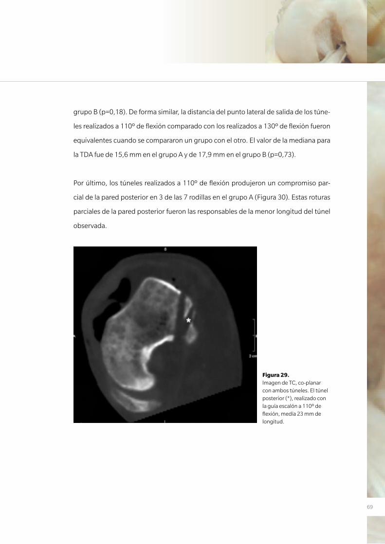
69
grupo B (p=0,18). De forma similar, la distancia del punto lateral de salida de los túne-
les realizados a 110º de flexión comparado con los realizados a 130º de flexión fueron
equivalentes cuando se compararon un grupo con el otro. El valor de la mediana para
la TDA fue de 15,6 mm en el grupo A y de 17,9 mm en el grupo B (p=0,73).
Por último, los túneles realizados a 110º de flexión produjeron un compromiso par-
cial de la pared posterior en 3 de las 7 rodillas en el grupo A (Figura 30). Estas roturas
parciales de la pared posterior fueron las responsables de la menor longitud del túnel
observada.
Figura 29. Imagen de TC, co-planar con ambos túneles. El túnel posterior (*), realizado con la guía escalón a 110º de flexión, medía 23 mm de longitud.
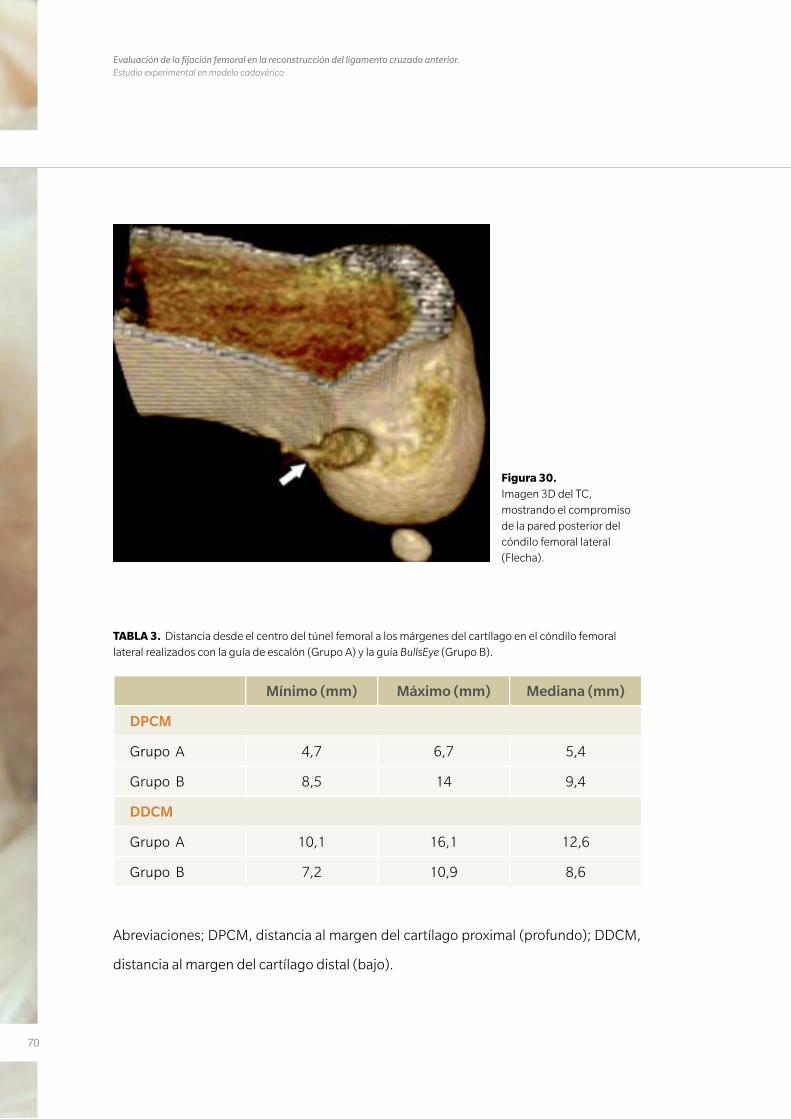
70
Evaluación de la fijación femoral en la reconstrucción del ligamento cruzado anterior. Estudio experimental en modelo cadavérico
Figura 30. Imagen 3D del TC, mostrando el compromiso de la pared posterior del cóndilo femoral lateral (Flecha).
TABLA 3. Distancia desde el centro del túnel femoral a los márgenes del cartílago en el cóndilo femoral lateral realizados con la guía de escalón (Grupo A) y la guía BullsEye (Grupo B).
Mínimo (mm) Máximo (mm) Mediana (mm)
DPCM
Grupo A 4,7 6,7 5,4
Grupo B 8,5 14 9,4
DDCM
Grupo A 10,1 16,1 12,6
Grupo B 7,2 10,9 8,6
Abreviaciones; DPCM, distancia al margen del cartílago proximal (profundo); DDCM,
distancia al margen del cartílago distal (bajo).
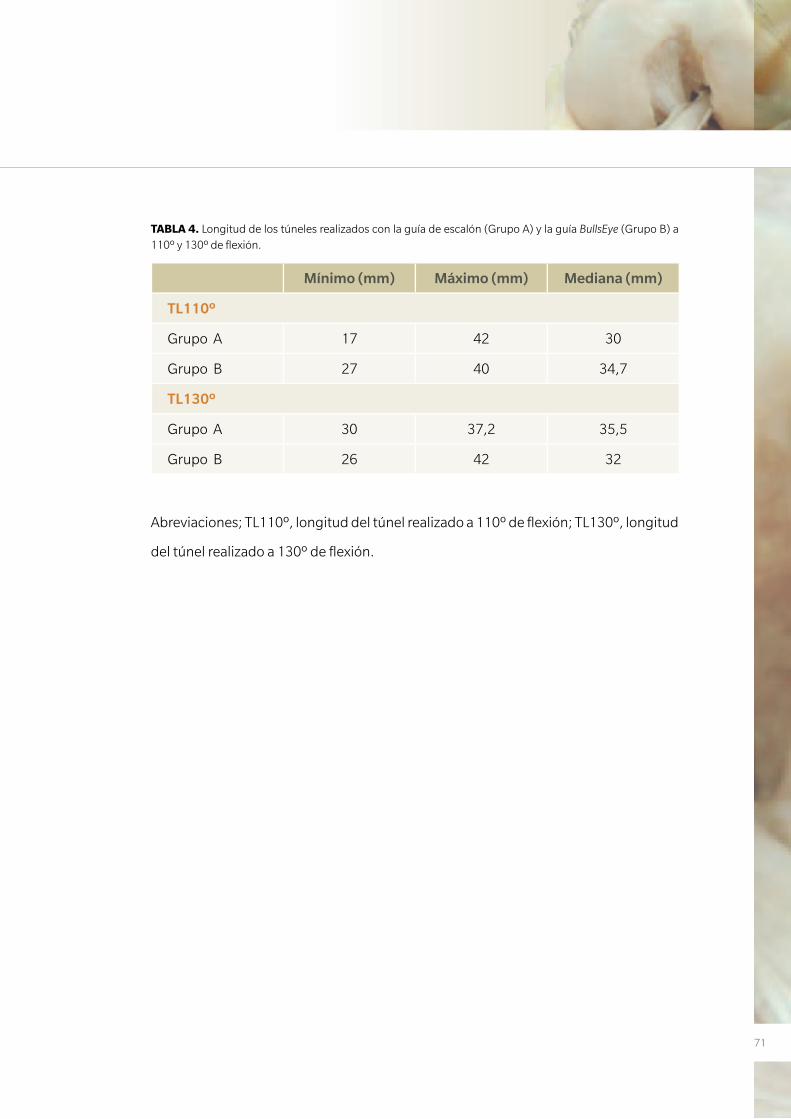
71
TABLA 4. Longitud de los túneles realizados con la guía de escalón (Grupo A) y la guía BullsEye (Grupo B) a 110º y 130º de flexión.
Mínimo (mm) Máximo (mm) Mediana (mm)
TL110º
Grupo A 17 42 30
Grupo B 27 40 34,7
TL130º
Grupo A 30 37,2 35,5
Grupo B 26 42 32
Abreviaciones; TL110º, longitud del túnel realizado a 110º de flexión; TL130º, longitud
del túnel realizado a 130º de flexión.

72
Evaluación de la fijación femoral en la reconstrucción del ligamento cruzado anterior. Estudio experimental en modelo cadavérico

7373
D I S C U S I Ó N
4. DISCUSIÓN

74
Evaluación de la fijación femoral en la reconstrucción del ligamento cruzado anterior. Estudio experimental en modelo cadavérico
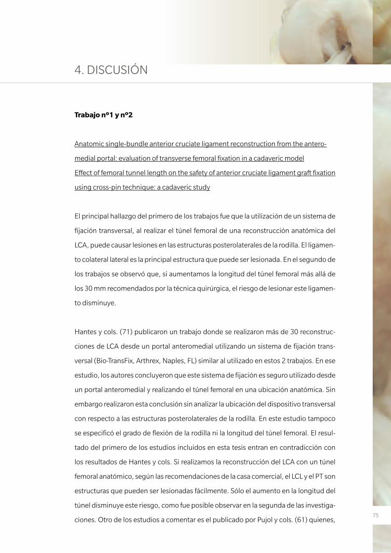
75
4. DISCUSIÓN
Trabajo nº1 y nº2
Anatomic single-bundle anterior cruciate ligament reconstruction from the antero-
medial portal: evaluation of transverse femoral fixation in a cadaveric model
Effect of femoral tunnel length on the safety of anterior cruciate ligament graft fixation
using cross-pin technique: a cadaveric study
El principal hallazgo del primero de los trabajos fue que la utilización de un sistema de
fijación transversal, al realizar el túnel femoral de una reconstrucción anatómica del
LCA, puede causar lesiones en las estructuras posterolaterales de la rodilla. El ligamen-
to colateral lateral es la principal estructura que puede ser lesionada. En el segundo de
los trabajos se observó que, si aumentamos la longitud del túnel femoral más allá de
los 30 mm recomendados por la técnica quirúrgica, el riesgo de lesionar este ligamen-
to disminuye.
Hantes y cols. (71) publicaron un trabajo donde se realizaron más de 30 reconstruc-
ciones de LCA desde un portal anteromedial utilizando un sistema de fijación trans-
versal (Bio-TransFix, Arthrex, Naples, FL) similar al utilizado en estos 2 trabajos. En ese
estudio, los autores concluyeron que este sistema de fijación es seguro utilizado desde
un portal anteromedial y realizando el túnel femoral en una ubicación anatómica. Sin
embargo realizaron esta conclusión sin analizar la ubicación del dispositivo transversal
con respecto a las estructuras posterolaterales de la rodilla. En este estudio tampoco
se especificó el grado de flexión de la rodilla ni la longitud del túnel femoral. El resul-
tado del primero de los estudios incluidos en esta tesis entran en contradicción con
los resultados de Hantes y cols. Si realizamos la reconstrucción del LCA con un túnel
femoral anatómico, según las recomendaciones de la casa comercial, el LCL y el PT son
estructuras que pueden ser lesionadas fácilmente. Sólo el aumento en la longitud del
túnel disminuye este riesgo, como fue posible observar en la segunda de las investiga-
ciones. Otro de los estudios a comentar es el publicado por Pujol y cols. (61) quienes,
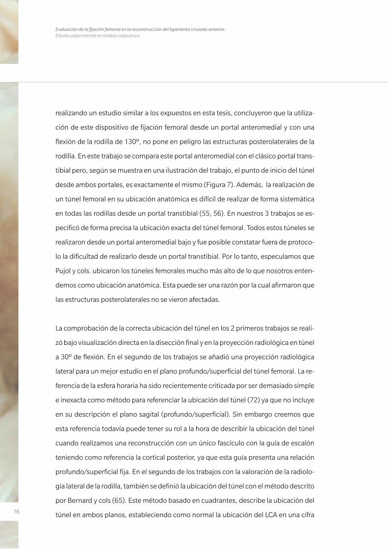
76
Evaluación de la fijación femoral en la reconstrucción del ligamento cruzado anterior. Estudio experimental en modelo cadavérico
realizando un estudio similar a los expuestos en esta tesis, concluyeron que la utiliza-
ción de este dispositivo de fijación femoral desde un portal anteromedial y con una
flexión de la rodilla de 130º, no pone en peligro las estructuras posterolaterales de la
rodilla. En este trabajo se compara este portal anteromedial con el clásico portal trans-
tibial pero, según se muestra en una ilustración del trabajo, el punto de inicio del túnel
desde ambos portales, es exactamente el mismo (Figura 7). Además, la realización de
un túnel femoral en su ubicación anatómica es difícil de realizar de forma sistemática
en todas las rodillas desde un portal transtibial (55, 56). En nuestros 3 trabajos se es-
pecificó de forma precisa la ubicación exacta del túnel femoral. Todos estos túneles se
realizaron desde un portal anteromedial bajo y fue posible constatar fuera de protoco-
lo la dificultad de realizarlo desde un portal transtibial. Por lo tanto, especulamos que
Pujol y cols. ubicaron los túneles femorales mucho más alto de lo que nosotros enten-
demos como ubicación anatómica. Esta puede ser una razón por la cual afirmaron que
las estructuras posterolaterales no se vieron afectadas.
La comprobación de la correcta ubicación del túnel en los 2 primeros trabajos se reali-
zó bajo visualización directa en la disección final y en la proyección radiológica en túnel
a 30º de flexión. En el segundo de los trabajos se añadió una proyección radiológica
lateral para un mejor estudio en el plano profundo/superficial del túnel femoral. La re-
ferencia de la esfera horaria ha sido recientemente criticada por ser demasiado simple
e inexacta como método para referenciar la ubicación del túnel (72) ya que no incluye
en su descripción el plano sagital (profundo/superficial). Sin embargo creemos que
esta referencia todavía puede tener su rol a la hora de describir la ubicación del túnel
cuando realizamos una reconstrucción con un único fascículo con la guía de escalón
teniendo como referencia la cortical posterior, ya que esta guía presenta una relación
profundo/superficial fija. En el segundo de los trabajos con la valoración de la radiolo-
gía lateral de la rodilla, también se definió la ubicación del túnel con el método descrito
por Bernard y cols (65). Este método basado en cuadrantes, describe la ubicación del
túnel en ambos planos, estableciendo como normal la ubicación del LCA en una cifra

77
porcentual 25% (alto/bajo) y 25% (superficial/profundo) (Figura 17). Estas cifras son
similares a las que presentamos en el segundo de los trabajos.
Otro de los aspectos a considerar es el grado de flexión de la rodilla en la identifica-
ción del punto de entrada y sobre todo en el brocado del túnel femoral. En nuestros
2 primeros estudios, el grado de flexión de la rodilla se estableció a 110º. Diferentes
estudios defienden este grado de flexión (70, 73) ya que el aumento de esta flexión a
130º o más provoca un túnel muy angulado con respecto al punto de entrada en el in-
tercóndilo provocando unas presiones demasiado importantes sobre la pared anterior
del túnel. Otros trabajos, como el ya comentado de Pujol y cols. (61), sugieren que no
hay peligro de lesionar estructuras posterolaterales de la rodilla a este grado de flexión.
De todas maneras hiperflexionar la rodilla más allá de 110º es difícil según que rodillas.
Se ha establecido como la longitud mínima recomendable para un túnel femoral en
25 mm (70). El hecho de descender el túnel femoral provoca que los túneles sean más
cortos (74), por lo cual el grado de flexión ha adquirido una mayor importancia a la
hora de realizar este túnel. De lo que no parece haber duda, a tenor de la múltiple bi-
bliografía reciente, es que restaurar la función del LCA con un túnel situado en su po-
sición anatómica restaura la estabilidad rotatoria de la rodilla mejor que si es colocado
en una posición no anatómica (42, 51, 52).
Las limitaciones de los 2 primeros estudios estaban en relación con que sólo se realizó
el estudio a 110º de flexión y no se valoraron angulaciones alternativas. Además, en el
primero de los estudios no se realizó una proyección radiológica lateral por lo que es
difícil evaluar la ubicación del túnel en el plano sagital. El hecho que la guía de entrada
del Cross Pin en el cóndilo lateral fuese sistemáticamente angulado en los recomenda-
dos 20º en dirección cefálica (60, 75) también limita las conclusiones a otras angula-
ciones posibles.
78
Evaluación de la fijación femoral en la reconstrucción del ligamento cruzado anterior. Estudio experimental en modelo cadavérico
En resumen, la fijación de la plastia en el lado femoral con el dispositivo estudiado pue-
de provocar lesiones en la región posterolateral de la rodilla cuando se realiza un túnel
anatómico de 30 mm. Sin embargo, alargar el túnel femoral tanto como permita el
cóndilo ha demostrado disminuir este riesgo.
79
Trabajo nº3
Effectiveness of a footprint guide to establish an anatomic femoral tunnel in anterior
cruciate ligament reconstruction: computed tomograpny evaluation in a cadaveric
model
El principal hallazgo del tercero de los trabajos fue que la guía femoral BullsEye es más
efectiva que la tradicional guía en escalón a la hora de situar un túnel lo más anatómico
posible. Por otra parte se observó que el grado de flexión de la rodilla no tiene relación
con la longitud del túnel, indistintamente de la guía usada. El grado de flexión de la ro-
dilla a la hora de iniciar el brocado del túnel femoral sigue siendo motivo de controver-
sia. Mientras tradicionalmente se ha definido que la hiperflexión de la rodilla aumenta
la longitud del túnel (70, 61), recientemente Bedi y cols. (69) presentaron unos resulta-
dos opuestos, objetivando una reducción en la longitud del túnel al mismo tiempo que
un mayor riesgo de lesión de la pared posterior del túnel. Este hallazgo fue atribuido
al uso de la guía de escalón desde el portal AM. En nuestro estudio, aunque no se ob-
servaron diferencias significativas en cuanto a la longitud del túnel a uno y otro grado
de flexión de la rodilla, la longitud observada en los túneles realizados con la ayuda
de la guía BullsEye fue superior a los realizados con la guía de escalón. Incluso en 3 de
los 10 túneles realizados a 110º con la guía de escalón se lesionaron parcialmente la
pared posterior de los túneles y además estos túneles fueron menores de 25 mm. Esto
sugiere que la guía BullsEye es más segura a la hora de realizar el túnel a este grado de
flexión.
Respecto al método de imagen para valorar la posición del túnel femoral, Forsythe y
cols. (67) describieron recientemente la posición de los dos haces del LCA en una re-
construcción en 3D-TC, mediante una adaptación del sistema del cuadrante. Obtuvie-
ron una posición en el plano profundo/superficial de 21,7% y 35,1% para el haz AM y
PL respectivamente y una posición respecto al plano alto/bajo de 33,2% y 55,3% para
80
Evaluación de la fijación femoral en la reconstrucción del ligamento cruzado anterior. Estudio experimental en modelo cadavérico
el haz AM y PL respectivamente. En los resultados del tercero de nuestros estudios,
con un único haz y mediante la guía de escalón, se obtuvo una mediana de 19,7% y
30,3% en el plano profundo/superficial y alto/bajo respectivamente. Estos resultados
se asemejan a los resultados para el haz AM del trabajo de Forsythe y cols. Por otro lado,
la ubicación del túnel con la guía BullsEye arroja unos resultados de 26,9% y 40,8% %
en el plano profundo/superficial y alto/bajo respectivamente. Estos resultados corres-
ponden a una posición intermedia óptima entre el haz AM y PL.
Una de las principales limitaciones de este estudio viene determinado por el núme-
ro de especímenes estudiados. Este hecho posiblemente este en relación con que en
varias comparaciones no se haya alcanzado una significación estadística. La otra limi-
tación más importante fue debida a que sólo se utilizaron las guía BullsEye de 8 mm y
la guía de escalón de 5 mm. Una guía en escalón de mayor tamaño podría acercar la
ubicación del túnel a una posición más anatómica.
8181
C O N C LU S I O N E S
5. CONCLUSIONES

82
Evaluación de la fijación femoral en la reconstrucción del ligamento cruzado anterior. Estudio experimental en modelo cadavérico
83
5. CONCLUSIONES
Anatomic single-bundle anterior cruciate ligament
reconstruction from the anteromedial portal: evaluation
of transverse femoral fixation in a cadaveric model.
La fijación de la plastia de isquiotibiales con el sistema Cross
Pin desde un portal anteromedial a 110º de flexión y con
un túnel de 30 mm colocado anatómicamente presenta
un mayor riesgo de lesión del ligamento colateral lateral.
Además, también aumenta el riesgo de lesión del tendón
poplíteo y el tendón del gemelo lateral.
1
84
Evaluación de la fijación femoral en la reconstrucción del ligamento cruzado anterior. Estudio experimental en modelo cadavérico
Effect of femoral tunnel length on the safety of anterior
cruciate ligament graft fixation using cross-pin
technique: a cadaveric study.
La fijación de la plastia de isquiotibiales con el sistema Cross Pin
ha demostrado ser segura cuando el túnel femoral se realiza
desde un portal anteromedial a 110º de flexión, siempre que
dicho túnel se realice tan largo como permita el cóndilo femo-
ral lateral.
2
85
Effectiveness of a footprint guide to establish an
anatomic femoral tunnel in anterior cruciate ligament
reconstruction: computed tomography evaluation in a
cadaveric model.
La guía BullsEye ha sido más precisa que la guía de escalón
estándar para situar el túnel femoral del LCA en una posición
anatómica. Además, con la guía en escalón de 5 mm se
obtuvieron túneles más cortos y con mayor riesgo de rotura
de la pared posterior del túnel.
Por otro lado se observó que el grado de flexión de la rodilla
no tiene relación con la longitud del túnel, indistintamente de
la guía usada.
3

86
Evaluación de la fijación femoral en la reconstrucción del ligamento cruzado anterior. Estudio experimental en modelo cadavérico

8787
C O P I A D E LO S T R A B A J O S
6. COPIA DE LOS TRABAJOS

88
Evaluación de la fijación femoral en la reconstrucción del ligamento cruzado anterior. Estudio experimental en modelo cadavérico
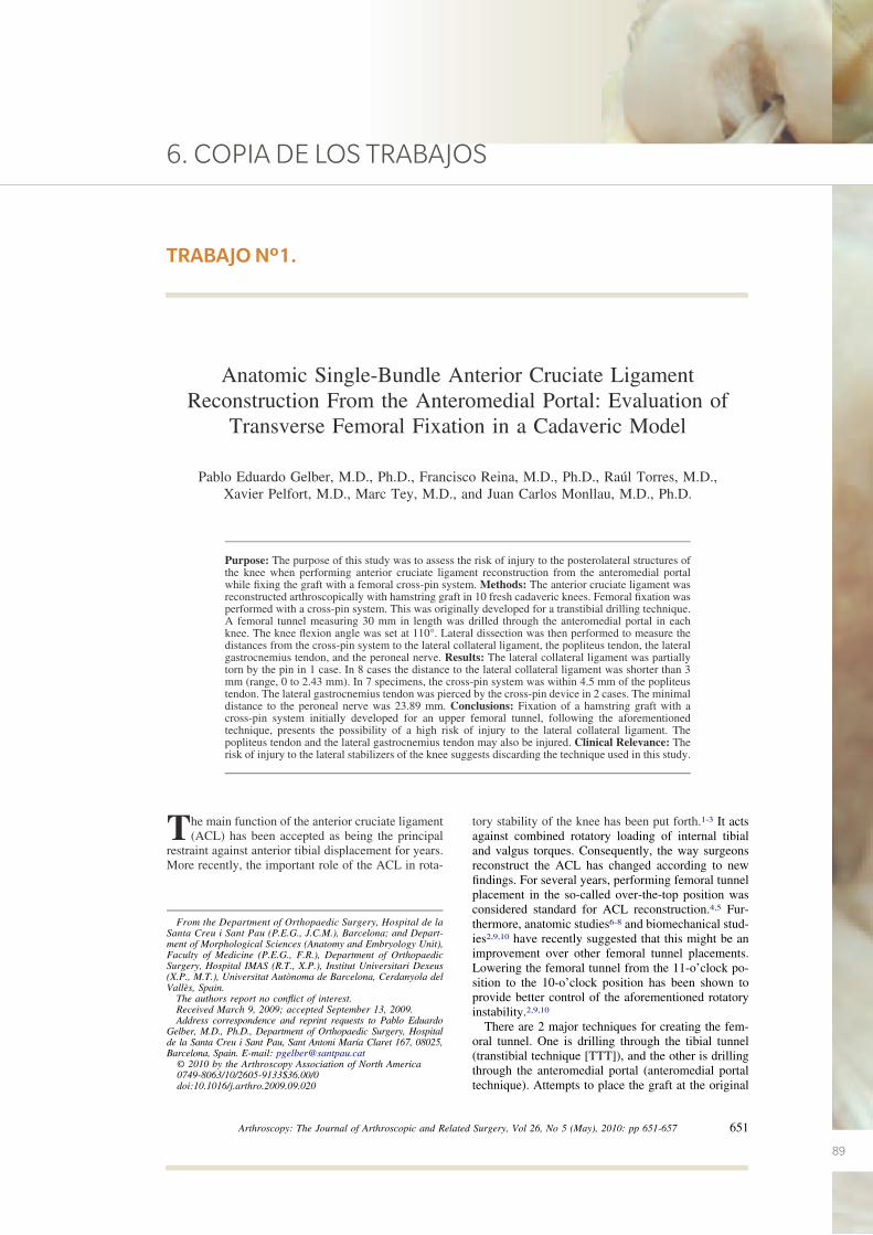
89
6. COPIA DE LOS TRABAJOS
Anatomic Single-Bundle Anterior Cruciate LigamentReconstruction From the Anteromedial Portal: Evaluation of
Transverse Femoral Fixation in a Cadaveric Model
Pablo Eduardo Gelber, M.D., Ph.D., Francisco Reina, M.D., Ph.D., Raúl Torres, M.D.,Xavier Pelfort, M.D., Marc Tey, M.D., and Juan Carlos Monllau, M.D., Ph.D.
Purpose: The purpose of this study was to assess the risk of injury to the posterolateral structures ofthe knee when performing anterior cruciate ligament reconstruction from the anteromedial portalwhile fixing the graft with a femoral cross-pin system. Methods: The anterior cruciate ligament wasreconstructed arthroscopically with hamstring graft in 10 fresh cadaveric knees. Femoral fixation wasperformed with a cross-pin system. This was originally developed for a transtibial drilling technique.A femoral tunnel measuring 30 mm in length was drilled through the anteromedial portal in eachknee. The knee flexion angle was set at 110°. Lateral dissection was then performed to measure thedistances from the cross-pin system to the lateral collateral ligament, the popliteus tendon, the lateralgastrocnemius tendon, and the peroneal nerve. Results: The lateral collateral ligament was partiallytorn by the pin in 1 case. In 8 cases the distance to the lateral collateral ligament was shorter than 3mm (range, 0 to 2.43 mm). In 7 specimens, the cross-pin system was within 4.5 mm of the popliteustendon. The lateral gastrocnemius tendon was pierced by the cross-pin device in 2 cases. The minimaldistance to the peroneal nerve was 23.89 mm. Conclusions: Fixation of a hamstring graft with across-pin system initially developed for an upper femoral tunnel, following the aforementionedtechnique, presents the possibility of a high risk of injury to the lateral collateral ligament. Thepopliteus tendon and the lateral gastrocnemius tendon may also be injured. Clinical Relevance: Therisk of injury to the lateral stabilizers of the knee suggests discarding the technique used in this study.
The main function of the anterior cruciate ligament(ACL) has been accepted as being the principal
restraint against anterior tibial displacement for years.More recently, the important role of the ACL in rota-
tory stability of the knee has been put forth.1-3 It actsagainst combined rotatory loading of internal tibialand valgus torques. Consequently, the way surgeonsreconstruct the ACL has changed according to newfindings. For several years, performing femoral tunnelplacement in the so-called over-the-top position wasconsidered standard for ACL reconstruction.4,5 Fur-thermore, anatomic studies6-8 and biomechanical stud-ies2,9,10 have recently suggested that this might be animprovement over other femoral tunnel placements.Lowering the femoral tunnel from the 11-o’clock po-sition to the 10-o’clock position has been shown toprovide better control of the aforementioned rotatoryinstability.2,9,10
There are 2 major techniques for creating the fem-oral tunnel. One is drilling through the tibial tunnel(transtibial technique [TTT]), and the other is drillingthrough the anteromedial portal (anteromedial portaltechnique). Attempts to place the graft at the original
From the Department of Orthopaedic Surgery, Hospital de laSanta Creu i Sant Pau (P.E.G., J.C.M.), Barcelona; and Depart-ment of Morphological Sciences (Anatomy and Embryology Unit),Faculty of Medicine (P.E.G., F.R.), Department of OrthopaedicSurgery, Hospital IMAS (R.T., X.P.), Institut Universitari Dexeus(X.P., M.T.), Universitat Autònoma de Barcelona, Cerdanyola delVallès, Spain.
The authors report no conflict of interest.Received March 9, 2009; accepted September 13, 2009.Address correspondence and reprint requests to Pablo Eduardo
Gelber, M.D., Ph.D., Department of Orthopaedic Surgery, Hospitalde la Santa Creu i Sant Pau, Sant Antoni María Claret 167, 08025,Barcelona, Spain. E-mail: [email protected]
© 2010 by the Arthroscopy Association of North America0749-8063/10/2605-9133$36.00/0doi:10.1016/j.arthro.2009.09.020
651Arthroscopy: The Journal of Arthroscopic and Related Surgery, Vol 26, No 5 (May), 2010: pp 651-657
TRABAJO Nº1.
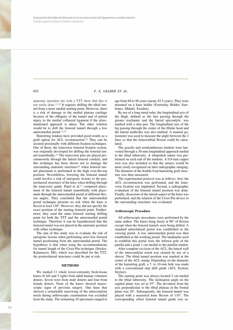
90
Evaluación de la fijación femoral en la reconstrucción del ligamento cruzado anterior. Estudio experimental en modelo cadavérico
anatomic insertion site with a TTT show that this isnot easily done.11,12 It requires drilling the tibial tun-nel from a more medial starting point. However, thereis a risk of damage to the medial plateau cartilagebecause of the obliquity of the tunnel and of partialinjury to the medial collateral ligament if the afore-mentioned approach is taken. The other solutionwould be to drill the femoral tunnel through a lowanteromedial portal.12,13
Hamstring tendons have provided good results as agraft option for ACL reconstruction.14 They can besecured proximally with different fixation techniques.One of these, the transverse femoral fixation system,was originally developed for drilling the femoral tun-nel transtibially.15 The transverse pins are placed per-cutaneously through the lateral femoral condyle, andthis technique has been shown not to damage thesurrounding anatomic structures16 when femoral tun-nel placement is performed in the high over-the-topposition. Nevertheless, lowering the femoral tunnelcould involve a risk of iatrogenic lesions to the pos-terolateral structures of the knee when drilling throughthe transverse guide. Pujol et al.17 compared place-ment of the femoral tunnel transtibially with place-ment through the anteromedial portal at different flex-ion angles. They concluded that the anteromedialportal technique presents no risk when the knee isflexed at least 130°. However, they did not specify theexact position of the starting femoral point. Further-more, they used the same femoral starting drillingpoint for both the TTT and the anteromedial portaltechnique. Therefore it can be hypothesized that thefemoral tunnel was not placed in the anatomic positionwith either technique.
The aim of this study was to evaluate the risk ofiatrogenic lesions when performing strict low femoraltunnel positioning from the anteromedial portal. Thehypothesis is that when using the recommendationsfor tunnel length of the Cross-Pin technique (Stryker,Kalamazoo, MI), which was described for the TTT,the posterolateral structures could be put at risk.
METHODS
We studied 11 whole lower-extremity fresh-tissueknees (6 left and 5 right) from adult human volunteerdonors. Seven were from male donors and four fromfemale donors. None of the knees showed macro-scopic signs of previous surgery. One knee thatshowed a remarkable narrowing of the intercondylarnotch during arthroscopic examination was excludedfrom the study. The remaining 10 specimens ranged in
age from 68 to 96 years (mean, 83.5 years). They weremounted on a knee holder (Extremity Holder; Saw-bones, Malmö, Sweden).
By use of a long metal ruler, the longitudinal axis ofthe thigh, defined as the line passing through thegreater trochanter and the lateral epicondyle, wasmarked with a skin pen. The longitudinal axis of theleg passing through the center of the fibular head andthe lateral malleolus was also marked. A manual go-niometer was used to measure the angle between the 2lines so that the femorotibial flexion could be calcu-lated.
The gracilis and semitendinosus tendons were har-vested through a 30-mm longitudinal approach medialto the tibial tuberosity. A whipstitch suture was per-formed on each end of the tendons. A 0.8-mm copperwire was also included so that the sutures would bemore easily recognized on later radiographic imaging.The diameter of the double-loop hamstring graft struc-ture was then measured.
The experimental protocol was as follows: first, theACL reconstruction was performed, and the trans-verse fixation was implanted. Second, a radiographicevaluation of the femoral tunnel position was done.Finally, dissection of the lateral aspect of the knee wasperformed, and the relation of the Cross-Pin device tothe surrounding structures was evaluated.
Arthroscopic Procedure
All arthroscopic procedures were performed by thesame author. The knees hung freely at 90° of flexionexcept when the femoral tunnels were being drilled. Astandard anterolateral portal was established as theviewing portal. A low anteromedial portal was thenestablished as the working portal. The landmarks usedto establish this portal were the inferior pole of thepatella and a point 1 cm medial to the patellar tendon.
After complete excision of the ACL, the lateral wallof the intercondylar notch was cleared by use of ashaver. The tibial tunnel position was marked at thecenter of the ACL stump. Depending on the diameterof the hamstring graft, a 7- to 10-mm hole was madewith a conventional step drill guide (ACL System;Stryker).
The starting point was always located 2 cm medialto the tibial tuberosity. The inclination angle on thesagittal plane was set at 55°. The deviation from theaxis perpendicular to the tibial plateau in the frontalplane was 20°. Subsequently, the femoral tunnel wasplaced with a measured knee flexion of 110°. Thecorresponding offset femoral tunnel guide was se-
652 P. E. GELBER ET AL.
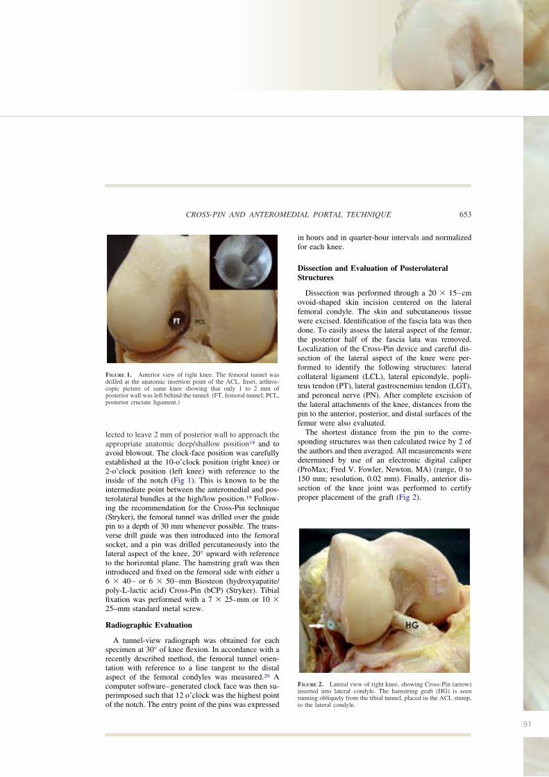
91
lected to leave 2 mm of posterior wall to approach theappropriate anatomic deep/shallow position18 and toavoid blowout. The clock-face position was carefullyestablished at the 10-o’clock position (right knee) or2-o’clock position (left knee) with reference to theinside of the notch (Fig 1). This is known to be theintermediate point between the anteromedial and pos-terolateral bundles at the high/low position.19 Follow-ing the recommendation for the Cross-Pin technique(Stryker), the femoral tunnel was drilled over the guidepin to a depth of 30 mm whenever possible. The trans-verse drill guide was then introduced into the femoralsocket, and a pin was drilled percutaneously into thelateral aspect of the knee, 20° upward with referenceto the horizontal plane. The hamstring graft was thenintroduced and fixed on the femoral side with either a6 � 40– or 6 � 50–mm Biosteon (hydroxyapatite/poly-L-lactic acid) Cross-Pin (bCP) (Stryker). Tibialfixation was performed with a 7 � 25–mm or 10 �25–mm standard metal screw.
Radiographic Evaluation
A tunnel-view radiograph was obtained for eachspecimen at 30° of knee flexion. In accordance with arecently described method, the femoral tunnel orien-tation with reference to a line tangent to the distalaspect of the femoral condyles was measured.20 Acomputer software–generated clock face was then su-perimposed such that 12 o’clock was the highest pointof the notch. The entry point of the pins was expressed
in hours and in quarter-hour intervals and normalizedfor each knee.
Dissection and Evaluation of PosterolateralStructures
Dissection was performed through a 20 � 15–cmovoid-shaped skin incision centered on the lateralfemoral condyle. The skin and subcutaneous tissuewere excised. Identification of the fascia lata was thendone. To easily assess the lateral aspect of the femur,the posterior half of the fascia lata was removed.Localization of the Cross-Pin device and careful dis-section of the lateral aspect of the knee were per-formed to identify the following structures: lateralcollateral ligament (LCL), lateral epicondyle, popli-teus tendon (PT), lateral gastrocnemius tendon (LGT),and peroneal nerve (PN). After complete excision ofthe lateral attachments of the knee, distances from thepin to the anterior, posterior, and distal surfaces of thefemur were also evaluated.
The shortest distance from the pin to the corre-sponding structures was then calculated twice by 2 ofthe authors and then averaged. All measurements weredetermined by use of an electronic digital caliper(ProMax; Fred V. Fowler, Newton, MA) (range, 0 to150 mm; resolution, 0.02 mm). Finally, anterior dis-section of the knee joint was performed to certifyproper placement of the graft (Fig 2).
FIGURE 2. Lateral view of right knee, showing Cross-Pin (arrow)inserted into lateral condyle. The hamstring graft (HG) is seenrunning obliquely from the tibial tunnel, placed in the ACL stump,to the lateral condyle.
FIGURE 1. Anterior view of right knee. The femoral tunnel wasdrilled at the anatomic insertion point of the ACL. Inset, arthros-copic picture of same knee showing that only 1 to 2 mm ofposterior wall was left behind the tunnel. (FT, femoral tunnel; PCL,posterior cruciate ligament.)
653CROSS-PIN AND ANTEROMEDIAL PORTAL TECHNIQUE
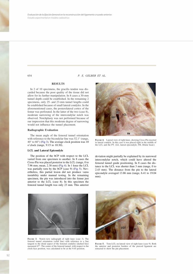
92
Evaluación de la fijación femoral en la reconstrucción del ligamento cruzado anterior. Estudio experimental en modelo cadavérico
RESULTS
In 2 of 10 specimens, the gracilis tendon was dis-carded because the poor quality of the tissue did notallow for its further manipulation. In 8 cases a 30-mmtunnel depth could be established. In the remaining 2specimens, only 25- and 23-mm tunnel lengths couldbe established because of small lateral condyles. In theaforementioned cases, the posterolateral cortex of thefemur was perforated. In the latter of the two (case 8),moderate narrowing of the intercondylar notch wasobserved. Notchplasty was not performed because ofour impression that this moderate degree of narrowingwould not influence the tunnel placement.
Radiographic Evaluation
The mean angle of the femoral tunnel orientationwith reference to the bicondylar line was 52.1° (range,40° to 60°) (Fig 3). The average clock position was 10o’clock (range, 9:15 to 10:30).
LCL and Lateral Epicondyle
The position of the bCP with respect to the LCLvaried from one specimen to another. In 8 cases theCross-Pin was placed posterior to the LCL (range, 0 to7.96 mm; mean, 2.38 mm) (Fig 4). In 1 knee the LCLwas partially torn by the bCP (case 9) (Fig 5). Nev-ertheless, this partial lesion did not produce varusinstability under manual testing. In the remainingspecimen, the pin was introduced into the femur justanterior to the LCL (case 8). In this specimen thefemoral tunnel length was only 23 mm. This anterior
deviation might partially be explained by its narrowedintercondylar notch, which could have altered thefemoral tunnel guide positioning. In 8 cases the dis-tance to the LCL was shorter than 3 mm (range, 0 to2.43 mm). The distance from the pin to the lateralepicondyle averaged 13.86 mm (range, 6.41 to 19.04mm).
FIGURE 3. Notch-view radiograph of right knee (case 3). Thefemoral tunnel orientation (solid line) with reference to a linetangent to the distal aspect of the femoral condyles (dashed line)measured 47°. The center of the femoral tunnel, with respect to theclock-face position, was calculated to be at the 9:45 position.
FIGURE 4. Lateral view of right knee, showing Cross-Pin insertedin lateral condyle. In this case it was placed right in the middle ofthe LCL and the PT. (LE, lateral epicondyle; FH, fibular head.)
FIGURE 5. Torn LCL on lateral view of right knee (case 9). Boththe anterior and posterior borders of the pierced ligament areretracted to show the pin placement.
654 P. E. GELBER ET AL.
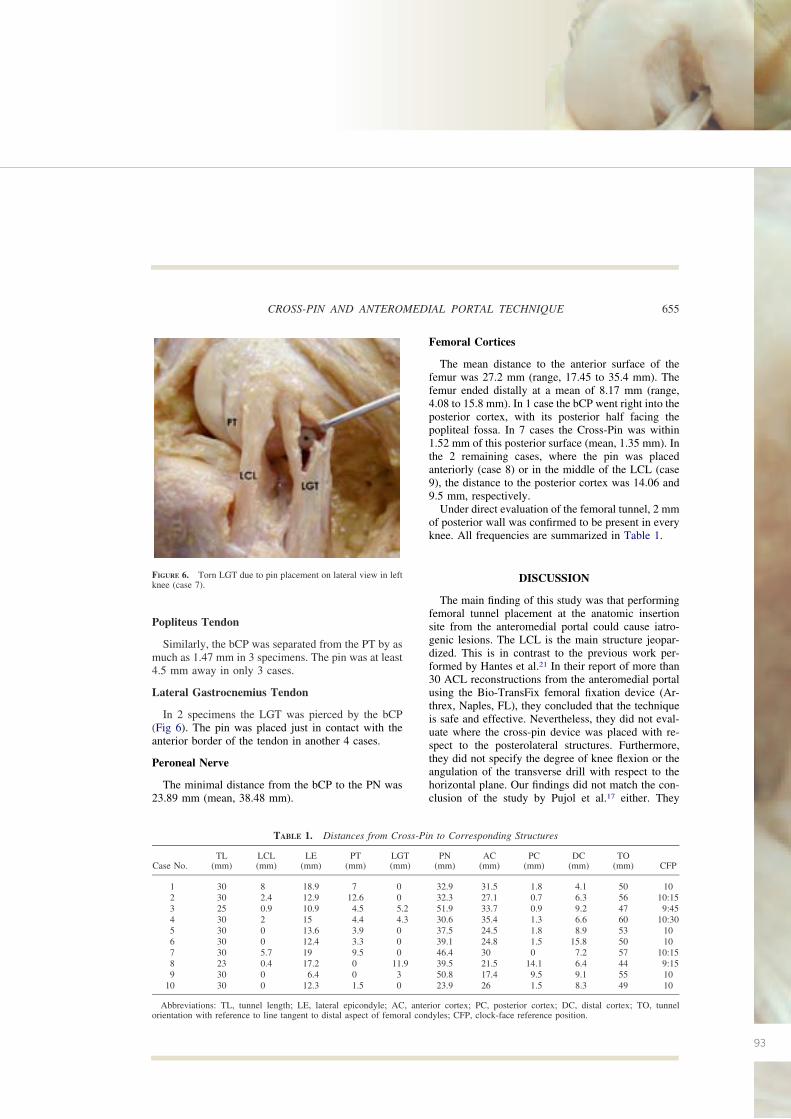
93
Popliteus Tendon
Similarly, the bCP was separated from the PT by asmuch as 1.47 mm in 3 specimens. The pin was at least4.5 mm away in only 3 cases.
Lateral Gastrocnemius Tendon
In 2 specimens the LGT was pierced by the bCP(Fig 6). The pin was placed just in contact with theanterior border of the tendon in another 4 cases.
Peroneal Nerve
The minimal distance from the bCP to the PN was23.89 mm (mean, 38.48 mm).
Femoral Cortices
The mean distance to the anterior surface of thefemur was 27.2 mm (range, 17.45 to 35.4 mm). Thefemur ended distally at a mean of 8.17 mm (range,4.08 to 15.8 mm). In 1 case the bCP went right into theposterior cortex, with its posterior half facing thepopliteal fossa. In 7 cases the Cross-Pin was within1.52 mm of this posterior surface (mean, 1.35 mm). Inthe 2 remaining cases, where the pin was placedanteriorly (case 8) or in the middle of the LCL (case9), the distance to the posterior cortex was 14.06 and9.5 mm, respectively.
Under direct evaluation of the femoral tunnel, 2 mmof posterior wall was confirmed to be present in everyknee. All frequencies are summarized in Table 1.
DISCUSSION
The main finding of this study was that performingfemoral tunnel placement at the anatomic insertionsite from the anteromedial portal could cause iatro-genic lesions. The LCL is the main structure jeopar-dized. This is in contrast to the previous work per-formed by Hantes et al.21 In their report of more than30 ACL reconstructions from the anteromedial portalusing the Bio-TransFix femoral fixation device (Ar-threx, Naples, FL), they concluded that the techniqueis safe and effective. Nevertheless, they did not eval-uate where the cross-pin device was placed with re-spect to the posterolateral structures. Furthermore,they did not specify the degree of knee flexion or theangulation of the transverse drill with respect to thehorizontal plane. Our findings did not match the con-clusion of the study by Pujol et al.17 either. They
FIGURE 6. Torn LGT due to pin placement on lateral view in leftknee (case 7).
TABLE 1. Distances from Cross-Pin to Corresponding Structures
Case No.TL
(mm)LCL(mm)
LE(mm)
PT(mm)
LGT(mm)
PN(mm)
AC(mm)
PC(mm)
DC(mm)
TO(mm) CFP
1 30 8 18.9 7 0 32.9 31.5 1.8 4.1 50 102 30 2.4 12.9 12.6 0 32.3 27.1 0.7 6.3 56 10:153 25 0.9 10.9 4.5 5.2 51.9 33.7 0.9 9.2 47 9:454 30 2 15 4.4 4.3 30.6 35.4 1.3 6.6 60 10:305 30 0 13.6 3.9 0 37.5 24.5 1.8 8.9 53 106 30 0 12.4 3.3 0 39.1 24.8 1.5 15.8 50 107 30 5.7 19 9.5 0 46.4 30 0 7.2 57 10:158 23 0.4 17.2 0 11.9 39.5 21.5 14.1 6.4 44 9:159 30 0 6.4 0 3 50.8 17.4 9.5 9.1 55 10
10 30 0 12.3 1.5 0 23.9 26 1.5 8.3 49 10
Abbreviations: TL, tunnel length; LE, lateral epicondyle; AC, anterior cortex; PC, posterior cortex; DC, distal cortex; TO, tunnelorientation with reference to line tangent to distal aspect of femoral condyles; CFP, clock-face reference position.
655CROSS-PIN AND ANTEROMEDIAL PORTAL TECHNIQUE
94
Evaluación de la fijación femoral en la reconstrucción del ligamento cruzado anterior. Estudio experimental en modelo cadavérico
concluded that there is no risk with the anteromedialportal technique when the knee is flexed at least 130°.However, they did not specify the exact position of thestarting femoral point. Furthermore, they used thesame femoral starting drilling point in the transtibialand the anteromedial portal techniques as shown intheir illustrations. Drilling the femoral tunnel at theanatomic position is not safely accomplished with theTTT.11,12 Placement of a low femoral tunnel, whichcould not have been reached with a TTT, was rigor-ously performed in all the specimens in our study.Therefore it can be speculated that what Pujol et al.placed was a high femoral tunnel near the high-noonpoint rather than performing an anatomic reconstruc-tion.
In this study the evaluation of the notch-view ra-diographs and, most importantly, the direct evaluationof the intercondylar notch during the final dissectionconfirmed that the grafts were properly orientedaround the anatomic insertional site at the 10-o’clockposition and with 2 mm of posterior back wall, cur-rently known as the high/low position and deep/shal-low position, respectively. This is very similar toprevious anatomic descriptions of the ACL femoralfootprint.18 It was also observed that the femoral tun-nel angulations with reference to a line tangent to thedistal aspect of the femoral condyles coincided withthe results described in a previous study.20 The clock-face reference method used for the femoral tunnelposition has recently been criticized as a simple butinaccurate method of tunnel referencing.22 It has beensaid that it only considers the high/low position butmisses the shallow/deep reference. This may be cor-rect when a double-bundle ACL reconstruction is be-ing performed. In the case of single-bundle recon-struction, because the step femoral guide is alwayslying below the posterior wall at the very same degreeof flexion, we believe that the cephalad/caudad orien-tation is the important factor in helping to performtunnel placement in the clinical setting. In this sensethe clock-face reference might still be valid.
The degree of knee flexion during drilling of thefemoral tunnel is controversial. In this study the flex-ion angle for performing the femoral tunnel was set at110°. Basdekis et al.20 have recently shown that with130° flexion or greater, the acuity of the tunnel withregard to the notch increases, leading to the graftincreasing pressure on the anterior tunnel wall. There-fore they recommended 110° of knee flexion. Thiswas also supported by recent work performed byNishimoto et al.23
Basdekis et al.20 have also recommended a mini-mum length of 25 mm for the femoral tunnel. In ourstudy only 1 specimen showed a slightly shorter tun-nel length. This could be partially explained by thefact that the moderate narrowing of the intercondylarnotch forces excessive anterior placement of the fem-oral tunnel guide when it is used through the antero-medial portal, and consequently, the fixation device isalso too anteriorly placed.
It has been shown that reconstructing the femoraltunnel at the center of the anatomic origin of the nativeACL more closely restores rotational stability to theknee than does the standard tunnel reconstruction atthe 11-o’clock position.2,9,10
There are some limitations to this study. Besidesthe aforementioned fact that we only performed thetechnique at a 110° knee flexion angle and the smallsample size, radiographic lateral projections werenot obtained. Thus the anterior-posterior situationof the femoral tunnel could not be evaluated radio-graphically. Nevertheless, the presence of a 2-mmposterior wall was confirmed under direct evalua-tion in the specimens. In addition, how varying thedrill angles for the Cross-Pin insertion could affectthe results was not studied. Finally, neither interob-server nor intraobserver reliability was calculatedfor the measurements.
Fixation of the graft on the femoral side with theCross-Pin device, which was initially developed for anupper femoral tunnel, may lead to iatrogenic lesionswhen the femoral tunnel is lowered. In this study wefollowed the same tunnel length recommendations asin the original placement of the graft (11 o’clock). A30-mm femoral tunnel showed a high risk of injury tothe LCL as well as to the PT. In 2 of the 10 specimensstudied, the Cross-Pin directly pierced the LGT. Nev-ertheless, these injuries may have no clinical rele-vance. On the other hand, this technique proved to besafe with respect to the PN, leaving a minimum dis-tance of 24 mm. We do not recommend the techniqueused in this study because of this risk of injury to theimportant lateral stabilizers of the knee. One of thealternatives is to change to a femoral fixation methodthat was previously shown to be safe.24 Another pos-sibility might be to adapt the technique of the Cross-Pin system to a more lateralized fixation. This mighthypothetically be accomplished with a longer femoraltunnel or with further knee flexion. Nevertheless, fur-ther basic research should be done before a broadrecommendation can be made.
656 P. E. GELBER ET AL.
95
CONCLUSIONS
Fixation of hamstring graft with the Cross-Pin sys-tem, originally designed for transtibial drilling whenperforming femoral tunnel placement from the antero-medial portal at 110° of knee flexion and with a tunnellength of 30 mm, shows a high risk of injury to theLCL. The PT and the LGT may also be injured.
REFERENCES
1. Kanamori A, Woo SL, Ma CB, et al. The forces in the anteriorcruciate ligament and knee kinematics during a simulatedpivot shift test: A human cadaveric study using robotic tech-nology. Arthroscopy 2000;16:633-639.
2. Loh JC, Fukuda Y, Tsuda E, Steadman RJ, Fu FH, Woo SL-Y.Knee stability and graft function following anterior cruciateligament reconstruction: Comparison between 11 o’clock and10 o’clock femoral tunnel placement. Arthroscopy 2003;3:297-304.
3. Markolf KL, Park S, Jackson SR, McAllister DR. Anterior-posterior and rotatory stability of single and double-bundleanterior cruciate ligament reconstructions. J Bone Joint SurgAm 2009;91:107-118.
4. Bylski-Austrow DI, Grood E, Hefzy M, Holden JP, Butler DL.Anterior cruciate ligament replacements: A mechanical studyof femoral attachment location, flexion angle at tensioning andinitial tension. J Orthop Res 1990;8:522-532.
5. Markolf KL, Hame S, Monte Hunter D, et al. Effects offemoral tunnel placement on knee laxity and forces in ananterior cruciate ligament graft. J Orthop Res 2002;5:1016-1024.
6. Giron F, Cuomo P, Aglietti P, Bull AMJ, Amis AA. Femoralattachment of the anterior cruciate ligament. Knee Surg SportsTraumatol Arthrosc 2006;14:250-256.
7. Petersen W, Zantop T. Anatomy of the anterior cruciate liga-ment with regard to its two bundles. Clin Orthop Relat Res2006;454:35-47.
8. Kopf S, Musahl V, Tashman S, Szczodri M, Shen W, Fu FH.A systematic review of the femoral origin and tibial insertionmorphology of the ACL. Knee Surg Sports Traumatol Ar-throsc 2009;17:213-219.
9. Scopp JM, Jasper LE, Belkoff SM, Moorman CT III. Theeffect of oblique femoral tunnel placement on rotational con-straint of the knee reconstructed using patellar tendon au-tografts. Arthroscopy 2004;3:294-299.
10. Musahl V, Plakseychuk A, VanScyoc A, et al. Varying fem-oral tunnels between the anatomical footprint and isometricpositions. Effect on kinematics of the anterior cruciate liga-ment-reconstructed knee. Am J Sport Med 2005;5:712-718.
11. Arnold MP, Kooloos J, van Kampen A. Single-incision tech-nique misses the anatomical femoral anterior cruciate ligament
insertion: A cadaveric study. Knee Surg Sports TraumatolArthrosc 2001;9:194-199.
12. Gavriilidis I, Motsis EK, Pakos EE, Georgoulis AD, MitsionisG, Xenakis TA. Transtibial versus anteromedial portal of thefemoral tunnel in ACL reconstruction: A cadaveric study.Knee 2008;15:364-367.
13. Harner C, Honkamp N, Ranawat AS. Anteromedial portaltechnique for creating the anterior cruciate ligament femoraltunnel. Arthroscopy 2008;24:113-115.
14. Harilainen A, Sandelin J. A prospective comparison of 3hamstring ACL fixation devices—Rigidfix, BioScrew, and In-trafix—Randomized into 4 groups with 2 years of follow-up.Am J Sport Med 2009;37:699-706.
15. Clark R, Olsen RE, Larson BJ, Goble EM, Farrer RP. Cross-pin femoral fixation: A new technique for hamstring anteriorcruciate ligament reconstruction of the knee. Arthroscopy1998;3:258-267.
16. McKeon BP, Gordon M, DeConciliis G, Scheller A. The safezone for femoral cross-pin fixation. An anatomical study. JKnee Surg 2007;20:285-288.
17. Pujol N, Thierry D, Bauer T, Hardy P. Transverse femoralfixation in anterior cruciate ligament (ACL) reconstructionwith hamstrings grafts: An anatomic study about the relation-ships between the transcondylar device and the posterolateralstructures of the knee. Knee Surg Sport Traumatol Arthrosc2006;14:724-729.
18. Colombet P, Robinson J, Christel P, et al. Morphology ofanterior cruciate ligament attachments for anatomic recon-struction: A cadaveric dissection and radiographic study. Ar-throscopy 2006;22:984-992.
19. Rue JP, Ghodadra N, Bach BR Jr. Femoral tunnel placement insingle-bundle anterior cruciate ligament reconstruction: A ca-daveric study relating transtibial lateralized femoral tunnelposition to the anteromedial and posterolateral bundle femoralorigins of the anterior cruciate ligament. Am J Sports Med2008;36:73-79.
20. Basdekis G, Abisafi C, Christel P. Influence of knee flexionangle on femoral tunnel characteristics when drilled throughthe anteromedial portal during anterior cruciate ligament re-construction. Arthroscopy 2008;4:459-464.
21. Hantes M, Dailiana Z, Zachos V, Varitimidis S. Anteriorcruciate ligament reconstruction using the Bio-Transfix femo-ral fixation device and anteromedial portal technique. KneeSurg Sports Traumatol Arthrosc 2006;14:497:501.
22. Fu FH. The clock-face reference: Simple but nonanatomic.Arthroscopy 2008;24:1433, author reply 1434.
23. Nishimoto K, Kuroda R, Mizuno K, et al. Analysis of the graftbending angle at the femoral tunnel aperture in anatomicdouble bundle anterior cruciate ligament reconstruction: Acomparison of the transtibial and the far anteromedial portaltechnique. Knee Surg Sports Traumatol Arthrosc 2009;17:270-276.
24. Neven E, D’Hooghe P, Bellemans J. Double-bundle anteriorcruciate ligament reconstruction: A cadaveric study of theposterolateral tunnel position and safety of the lateral struc-tures. Arthroscopy 2008;4:436-440.
657CROSS-PIN AND ANTEROMEDIAL PORTAL TECHNIQUE
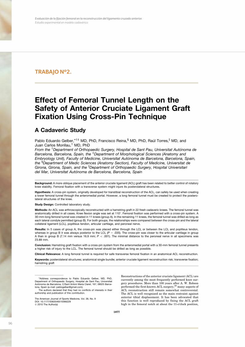
96
Evaluación de la fijación femoral en la reconstrucción del ligamento cruzado anterior. Estudio experimental en modelo cadavérico
TRABAJO Nº2.
Effect of Femoral Tunnel Length on theSafety of Anterior Cruciate Ligament GraftFixation Using Cross-Pin Technique
A Cadaveric Study
Pablo Eduardo Gelber,*yz MD, PhD, Francisco Reina,§ MD, PhD, Raul Torres,|| MD, andJuan Carlos Monllau,y MD, PhDFrom the yDepartment of Orthopaedic Surgery, Hospital de Sant Pau, Universitat Autonoma deBarcelona, Barcelona, Spain, the zDepartment of Morphological Sciences (Anatomy andEmbryology Unit), Faculty of Medicine, Universitat Autonoma de Barcelona, Barcelona, Spain,the §Department of Medic Sciences (Anatomy Section), Faculty of Medicine, Universitat deGirona, Girona, Spain, and the ||Department of Orthopaedic Surgery, Hospital Universitaridel Mar, Universitat Autonoma de Barcelona, Barcelona, Spain
Background: A more oblique placement of the anterior cruciate ligament (ACL) graft has been related to better control of rotatoryknee stability. Femoral fixation with a transverse system might injure its posterolateral structures.
Hypothesis: A cross-pin system, originally developed for transtibial reconstruction of the ACL, can safely be used when creatinga lower femoral tunnel through the anteromedial portal. However, a long femoral tunnel must be created to protect the postero-lateral structures of the knee.
Study Design: Controlled laboratory study.
Methods: An ACL was arthroscopically reconstructed with a hamstring graft in 22 fresh cadaveric knees. The femoral tunnel wasanatomically drilled in all cases. Knee flexion angle was set at 110�. Femoral fixation was performed with a cross-pin system. A30-mm-long femoral tunnel was created in 11 knees (group A). In the remaining 11 knees, the femoral tunnel was drilled as long aseach lateral condyle permitted (group B). For both groups, the relationships were compared between the cross-pin and the lateralcollateral ligament (LCL), popliteus tendon, articular cartilage, and peroneal nerve.
Results: In 5 cases of group A, the cross-pin was placed either through the LCL or between the LCL and popliteus tendon,whereas in group B it was always posterior to the LCL (P 5 .035). The cross-pin was closer to the articular cartilage in groupA than in group B (7.14 mm versus 16.9 mm; P \ .001). The minimal distance to the peroneal nerve in all specimens was23.89 mm.
Conclusion: Hamstring graft fixation with a cross-pin system from the anteromedial portal with a 30-mm femoral tunnel presentsa higher risk of injury to the LCL. The femoral tunnel should be drilled as long as possible.
Clinical Relevance: A long femoral tunnel is required for safe transverse femoral fixation in an anatomical ACL reconstruction.
Keywords: posterolateral structures; anatomical single bundle; anterior cruciate ligament reconstruction risk; transverse fixation;hamstring graft
Reconstructions of the anterior cruciate ligament (ACL) arecurrently among the most frequently performed knee sur-gery procedures. More than 100 years after A. W. Robsonperformed the first-known ACL surgery,28 many aspects ofACL reconstruction still remain somewhat controversial.The ACL is well recognized as the main restraint againstanterior tibial displacement. It has been advocated thatthis function is well reproduced by fixing the ACL grafthigh in the femoral notch at about the 11-o’clock position,
*Address correspondence to Pablo Eduardo Gelber, MD, PhD,Department of Orthopaedic Surgery, Hospital de Sant Pau, UniversitatAutonoma de Barcelona, C/Sant Antoni Maria Claret, 167, 08025 Barce-lona, Spain (e-mail: [email protected]).
The authors declared that they had no conflicts of interests in theirauthorship and publication of this contribution.
The American Journal of Sports Medicine, Vol. 38, No. 9DOI: 10.1177/0363546510366229� 2010 The Author(s)
1877
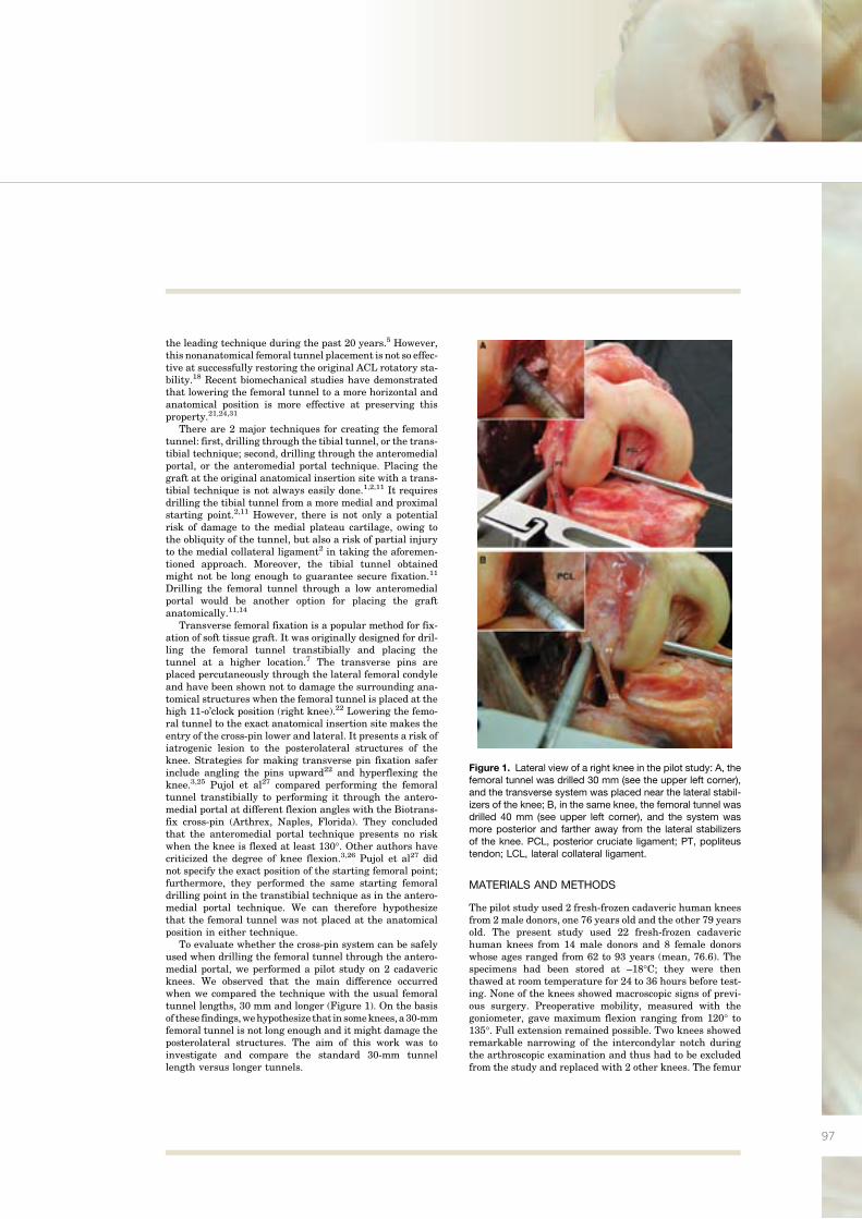
97
the leading technique during the past 20 years.5 However,this nonanatomical femoral tunnel placement is not so effec-tive at successfully restoring the original ACL rotatory sta-bility.18 Recent biomechanical studies have demonstratedthat lowering the femoral tunnel to a more horizontal andanatomical position is more effective at preserving thisproperty.21,24,31
There are 2 major techniques for creating the femoraltunnel: first, drilling through the tibial tunnel, or the trans-tibial technique; second, drilling through the anteromedialportal, or the anteromedial portal technique. Placing thegraft at the original anatomical insertion site with a trans-tibial technique is not always easily done.1,2,11 It requiresdrilling the tibial tunnel from a more medial and proximalstarting point.2,11 However, there is not only a potentialrisk of damage to the medial plateau cartilage, owing tothe obliquity of the tunnel, but also a risk of partial injuryto the medial collateral ligament2 in taking the aforemen-tioned approach. Moreover, the tibial tunnel obtainedmight not be long enough to guarantee secure fixation.11
Drilling the femoral tunnel through a low anteromedialportal would be another option for placing the graftanatomically.11,14
Transverse femoral fixation is a popular method for fix-ation of soft tissue graft. It was originally designed for dril-ling the femoral tunnel transtibially and placing thetunnel at a higher location.7 The transverse pins areplaced percutaneously through the lateral femoral condyleand have been shown not to damage the surrounding ana-tomical structures when the femoral tunnel is placed at thehigh 11-o’clock position (right knee).22 Lowering the femo-ral tunnel to the exact anatomical insertion site makes theentry of the cross-pin lower and lateral. It presents a risk ofiatrogenic lesion to the posterolateral structures of theknee. Strategies for making transverse pin fixation saferinclude angling the pins upward22 and hyperflexing theknee.3,25 Pujol et al27 compared performing the femoraltunnel transtibially to performing it through the antero-medial portal at different flexion angles with the Biotrans-fix cross-pin (Arthrex, Naples, Florida). They concludedthat the anteromedial portal technique presents no riskwhen the knee is flexed at least 130�. Other authors havecriticized the degree of knee flexion.3,26 Pujol et al27 didnot specify the exact position of the starting femoral point;furthermore, they performed the same starting femoraldrilling point in the transtibial technique as in the antero-medial portal technique. We can therefore hypothesizethat the femoral tunnel was not placed at the anatomicalposition in either technique.
To evaluate whether the cross-pin system can be safelyused when drilling the femoral tunnel through the antero-medial portal, we performed a pilot study on 2 cadavericknees. We observed that the main difference occurredwhen we compared the technique with the usual femoraltunnel lengths, 30 mm and longer (Figure 1). On the basisof these findings,wehypothesize that in someknees,a30-mmfemoral tunnel is not long enough and it might damage theposterolateral structures. The aim of this work was toinvestigate and compare the standard 30-mm tunnellength versus longer tunnels.
MATERIALS AND METHODS
The pilot study used 2 fresh-frozen cadaveric human kneesfrom 2 male donors, one 76 years old and the other 79 yearsold. The present study used 22 fresh-frozen cadaverichuman knees from 14 male donors and 8 female donorswhose ages ranged from 62 to 93 years (mean, 76.6). Thespecimens had been stored at –18�C; they were thenthawed at room temperature for 24 to 36 hours before test-ing. None of the knees showed macroscopic signs of previ-ous surgery. Preoperative mobility, measured with thegoniometer, gave maximum flexion ranging from 120� to135�. Full extension remained possible. Two knees showedremarkable narrowing of the intercondylar notch duringthe arthroscopic examination and thus had to be excludedfrom the study and replaced with 2 other knees. The femur
Figure 1. Lateral view of a right knee in the pilot study: A, thefemoral tunnel was drilled 30 mm (see the upper left corner),and the transverse system was placed near the lateral stabil-izers of the knee; B, in the same knee, the femoral tunnel wasdrilled 40 mm (see upper left corner), and the system wasmore posterior and farther away from the lateral stabilizersof the knee. PCL, posterior cruciate ligament; PT, popliteustendon; LCL, lateral collateral ligament.
1878 Gelber et al The American Journal of Sports Medicineaded from
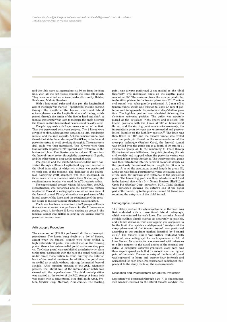
98
Evaluación de la fijación femoral en la reconstrucción del ligamento cruzado anterior. Estudio experimental en modelo cadavérico
and the tibia were cut approximately 30 cm from the jointline, with all the soft tissue around the knee left intact.They were mounted on a knee holder (Extremity Holder,Sawbones, Malmo, Sweden).
With a long metal ruler and skin pen, the longitudinalaxis of the thigh was marked—specifically, the line passingthrough the middle of the femoral shaft and lateralepicondyle—as was the longitudinal axis of the leg, whichpassed through the center of the fibular head and shaft. Amanual goniometer was used to measure the angle betweenthe 2 lines so that femorotibial flexion could be calculated.
The pilot approach with 2 specimenswas carried out first.This was performed with open surgery. The 2 knees werestripped of skin, subcutaneous tissue, facia lata, quadricepsmuscle, and the knee capsule. A 9-mm femoral tunnel wasthendrilled at the femoral stumpof theACLupto the femoralposterior cortex, to avoid breaking through it. The transversedrill guide was then introduced. Two K-wires were thentransversally implanted 20� upward with reference to thehorizontal plane. One K-wire was introduced 30 mm intothe femoral tunnel socket through the transverse drill guide,and the other went as deep as the tunnel allowed.
The gracilis and the semitendinosus tendons were har-vested through a 30-mm longitudinal approach medial tothe tibial tuberosity. A whipstitch suture was performedon each end of the tendons. The diameter of the double-loop hamstring graft structure was then measured. Inthose cases with a diameter wider than 9 mm, only thesemitendinosus tendon was used for ACL reconstruction.
The experimental protocol was as follows: First, the ACLreconstruction was performed and the transverse fixationimplanted. Second, a radiographic evaluation was done ofthe femoral tunnel. Finally, dissection was performed of thelateral aspect of the knee, and the relationship of the cross-pin device to the surrounding structures was evaluated.
The knees had been randomized into 2 groups: a 30-mmfemoral tunnel socket was performed for the 11 knees com-posing group A; for those 11 knees making up group B, thefemoral tunnel was drilled as long as the lateral condylepermitted in each case.
Arthroscopic Procedure
The same author (P.E.G.) performed all the arthroscopicprocedures. The knees hung freely at a 90� of flexion,except when the femoral tunnels were being drilled. Ahigh anterolateral portal was established as the viewingportal, then a low anteromedial portal as the working por-tal. The latter portal was established as inferiorly (ie, closeto the tibia) as possible with the help of a spinal needle andunder direct visualization to avoid injuring the anteriorhorn of the medial meniscus. In addition, the portal wasas medial as possible without injuring the medial femoralcondyle. After complete excision of the ACL, wheneverpresent, the lateral wall of the intercondylar notch wascleared with the help of a shaver. The tibial tunnel positionwas marked at the center of the ACL stump. A 9-mm holewas made with a conventional step drill guide (ACL Sys-tem, Stryker Corp, Mahwah, New Jersey). The starting
point was always performed 2 cm medial to the tibialtuberosity. The inclination angle on the sagittal planewas set at 55�. The deviation from the axis perpendicularto the tibial plateau in the frontal plane was 20�. The fem-oral tunnel was subsequently performed. A 7-mm offsetfemoral tunnel guide was selected to leave 2.5 mm of pos-terior wall to approach the anatomical deep/shallow posi-tion. The high/low position was calculated following theclock-face reference position. The guide was carefullyplaced at the 10-o’clock (right knees) and 2-o’clock (leftknees) positions with the knees at 90� of tibiofemoralflexion, and the starting point was marked—namely, theintermediate point between the anteromedial and postero-lateral bundles on the high/low position.29 The knee wasthen flexed to 110�, and the femoral tunnel was drilledover the guide pin. Based on the recommendation of thecross-pin technique (Stryker Corp), the femoral tunnelwas drilled over the guide pin to a depth of 30 mm in 11specimens (group A). In the remaining 11 knees (GroupB), the tunnel was drilled over the guide pin along the lat-eral condyle and stopped when the posterior cortex wasreached, to not break through it. The transverse drill guidewas then introduced into the femoral socket as deeply asthe previously determined tunnel length (at 30 mm ingroup A or at the maximum tunnel length in group B),and a pin was drilled percutaneously into the lateral aspectof the knee, 20� upward with reference to the horizontalplane. The hamstring graft was then introduced and fixedin the femoral side with a 6-3 50-mm Biosteon (HA/PLLA)Cross-Pin (Stryker Corp; hereafter, BCP). Tibial fixationwas performed securing the suture’s end of the distalpart of the hamstring to the periosteum and fat tissue sur-rounding the entry site of the tibial tunnel.
Radiographic Evaluation
The relative position of the femoral tunnel in the notch wasfirst evaluated with a conventional lateral radiograph,which was obtained for each knee. The posterior femoralcondyle outlines should overlap as accurately as possible,and a 6-mm deviation from overlapping was suggested tobe the limit of acceptable malalignment.9 Analysis of theentry placement of the femoral tunnel was performedaccording to the quadrant method described by Bernardet al.4 The femoral tunnel was further evaluated witha tunnel view radiograph for each specimen at 30� ofknee flexion. Its orientation was measured with referenceto a line tangent to the distal aspect of the femoral con-dyles. A computer software–generated clock face wasthen superimposed such that 12 o’clock was the highestpoint of the notch. The center entry of the femoral tunnelwas expressed in hours and quarter-hour intervals andnormalized for each knee. An experienced radiologist inde-pendent to the study made all the measurements.
Dissection and Posterolateral Structures Evaluation
Dissection was performed through a 20- 3 15-cm skin inci-sion window centered on the lateral femoral condyle. The
Vol. 38, No. 9, 2010 Cross-Pin and Anatomic ACL Reconstruction 1879s.sagepub.com
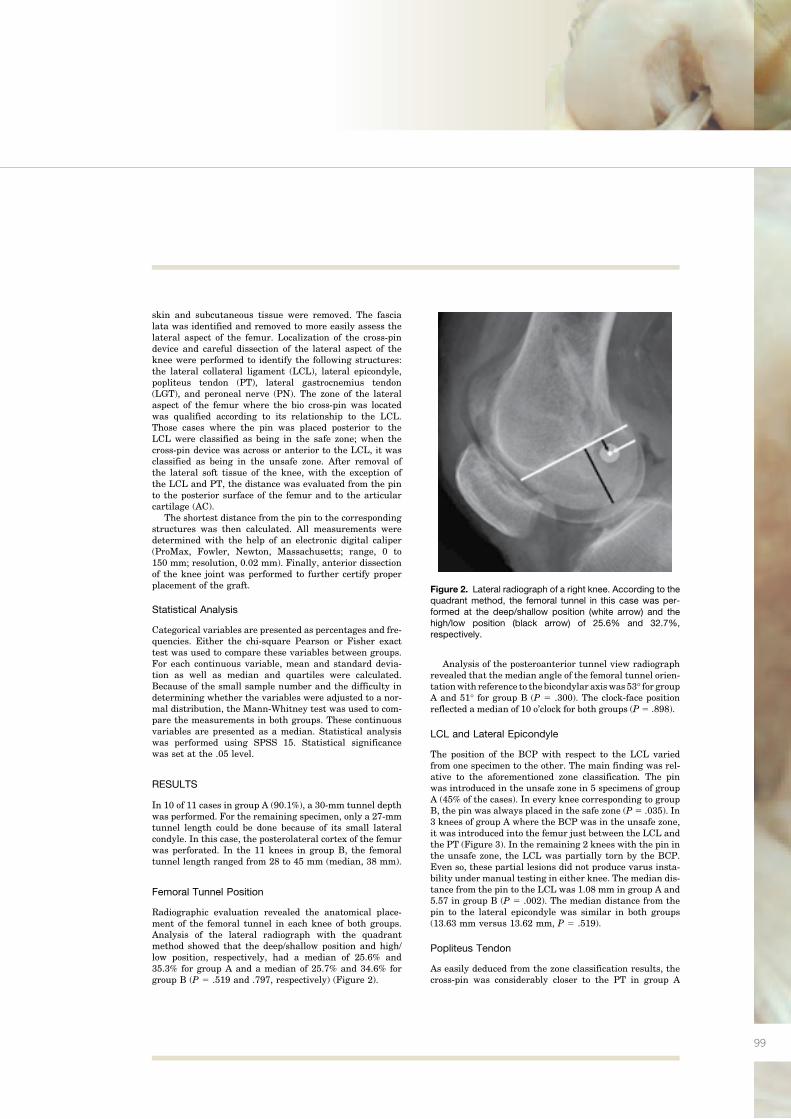
99
skin and subcutaneous tissue were removed. The fascialata was identified and removed to more easily assess thelateral aspect of the femur. Localization of the cross-pindevice and careful dissection of the lateral aspect of theknee were performed to identify the following structures:the lateral collateral ligament (LCL), lateral epicondyle,popliteus tendon (PT), lateral gastrocnemius tendon(LGT), and peroneal nerve (PN). The zone of the lateralaspect of the femur where the bio cross-pin was locatedwas qualified according to its relationship to the LCL.Those cases where the pin was placed posterior to theLCL were classified as being in the safe zone; when thecross-pin device was across or anterior to the LCL, it wasclassified as being in the unsafe zone. After removal ofthe lateral soft tissue of the knee, with the exception ofthe LCL and PT, the distance was evaluated from the pinto the posterior surface of the femur and to the articularcartilage (AC).
The shortest distance from the pin to the correspondingstructures was then calculated. All measurements weredetermined with the help of an electronic digital caliper(ProMax, Fowler, Newton, Massachusetts; range, 0 to150 mm; resolution, 0.02 mm). Finally, anterior dissectionof the knee joint was performed to further certify properplacement of the graft.
Statistical Analysis
Categorical variables are presented as percentages and fre-quencies. Either the chi-square Pearson or Fisher exacttest was used to compare these variables between groups.For each continuous variable, mean and standard devia-tion as well as median and quartiles were calculated.Because of the small sample number and the difficulty indetermining whether the variables were adjusted to a nor-mal distribution, the Mann-Whitney test was used to com-pare the measurements in both groups. These continuousvariables are presented as a median. Statistical analysiswas performed using SPSS 15. Statistical significancewas set at the .05 level.
RESULTS
In 10 of 11 cases in group A (90.1%), a 30-mm tunnel depthwas performed. For the remaining specimen, only a 27-mmtunnel length could be done because of its small lateralcondyle. In this case, the posterolateral cortex of the femurwas perforated. In the 11 knees in group B, the femoraltunnel length ranged from 28 to 45 mm (median, 38 mm).
Femoral Tunnel Position
Radiographic evaluation revealed the anatomical place-ment of the femoral tunnel in each knee of both groups.Analysis of the lateral radiograph with the quadrantmethod showed that the deep/shallow position and high/low position, respectively, had a median of 25.6% and35.3% for group A and a median of 25.7% and 34.6% forgroup B (P 5 .519 and .797, respectively) (Figure 2).
Analysis of the posteroanterior tunnel view radiographrevealed that the median angle of the femoral tunnel orien-tationwith reference to thebicondylar axiswas 53� for groupA and 51� for group B (P 5 .300). The clock-face positionreflected a median of 10 o’clock for both groups (P 5 .898).
LCL and Lateral Epicondyle
The position of the BCP with respect to the LCL variedfrom one specimen to the other. The main finding was rel-ative to the aforementioned zone classification. The pinwas introduced in the unsafe zone in 5 specimens of groupA (45% of the cases). In every knee corresponding to groupB, the pin was always placed in the safe zone (P 5 .035). In3 knees of group A where the BCP was in the unsafe zone,it was introduced into the femur just between the LCL andthe PT (Figure 3). In the remaining 2 knees with the pin inthe unsafe zone, the LCL was partially torn by the BCP.Even so, these partial lesions did not produce varus insta-bility under manual testing in either knee. The median dis-tance from the pin to the LCL was 1.08 mm in group A and5.57 in group B (P 5 .002). The median distance from thepin to the lateral epicondyle was similar in both groups(13.63 mm versus 13.62 mm, P 5 .519).
Popliteus Tendon
As easily deduced from the zone classification results, thecross-pin was considerably closer to the PT in group A
Figure 2. Lateral radiograph of a right knee. According to thequadrant method, the femoral tunnel in this case was per-formed at the deep/shallow position (white arrow) and thehigh/low position (black arrow) of 25.6% and 32.7%,respectively.
1880 Gelber et al The American Journal of Sports Medicine
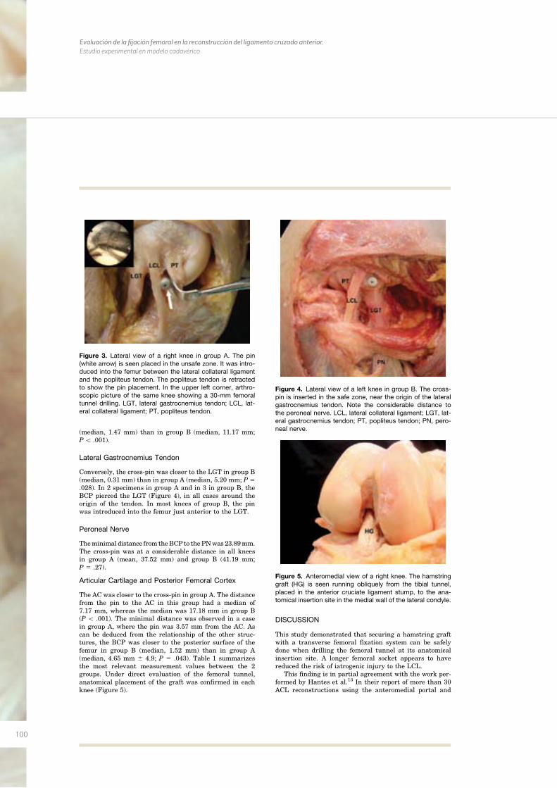
100
Evaluación de la fijación femoral en la reconstrucción del ligamento cruzado anterior. Estudio experimental en modelo cadavérico
(median, 1.47 mm) than in group B (median, 11.17 mm;P\ .001).
Lateral Gastrocnemius Tendon
Conversely, the cross-pin was closer to the LGT in group B(median, 0.31 mm) than in group A (median, 5.20 mm; P 5.028). In 2 specimens in group A and in 3 in group B, theBCP pierced the LGT (Figure 4), in all cases around theorigin of the tendon. In most knees of group B, the pinwas introduced into the femur just anterior to the LGT.
Peroneal Nerve
Theminimal distance from theBCP to thePNwas 23.89mm.The cross-pin was at a considerable distance in all kneesin group A (mean, 37.52 mm) and group B (41.19 mm;P 5 .27).
Articular Cartilage and Posterior Femoral Cortex
The AC was closer to the cross-pin in group A. The distancefrom the pin to the AC in this group had a median of7.17 mm, whereas the median was 17.18 mm in group B(P \ .001). The minimal distance was observed in a casein group A, where the pin was 3.57 mm from the AC. Ascan be deduced from the relationship of the other struc-tures, the BCP was closer to the posterior surface of thefemur in group B (median, 1.52 mm) than in group A(median, 4.65 mm 6 4.9; P 5 .043). Table 1 summarizesthe most relevant measurement values between the 2groups. Under direct evaluation of the femoral tunnel,anatomical placement of the graft was confirmed in eachknee (Figure 5).
DISCUSSION
This study demonstrated that securing a hamstring graftwith a transverse femoral fixation system can be safelydone when drilling the femoral tunnel at its anatomicalinsertion site. A longer femoral socket appears to havereduced the risk of iatrogenic injury to the LCL.
This finding is in partial agreement with the work per-formed by Hantes et al.13 In their report of more than 30ACL reconstructions using the anteromedial portal and
Figure 3. Lateral view of a right knee in group A. The pin(white arrow) is seen placed in the unsafe zone. It was intro-duced into the femur between the lateral collateral ligamentand the popliteus tendon. The popliteus tendon is retractedto show the pin placement. In the upper left corner, arthro-scopic picture of the same knee showing a 30-mm femoraltunnel drilling. LGT, lateral gastrocnemius tendon; LCL, lat-eral collateral ligament; PT, popliteus tendon.
Figure 4. Lateral view of a left knee in group B. The cross-pin is inserted in the safe zone, near the origin of the lateralgastrocnemius tendon. Note the considerable distance tothe peroneal nerve. LCL, lateral collateral ligament; LGT, lat-eral gastrocnemius tendon; PT, popliteus tendon; PN, pero-neal nerve.
Figure 5. Anteromedial view of a right knee. The hamstringgraft (HG) is seen running obliquely from the tibial tunnel,placed in the anterior cruciate ligament stump, to the ana-tomical insertion site in the medial wall of the lateral condyle.
Vol. 38, No. 9, 2010 Cross-Pin and Anatomic ACL Reconstruction 1881
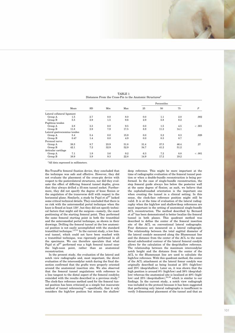
101
Bio-TransFix femoral fixation device, they concluded thatthe technique was safe and effective. However, they didnot evaluate the placement of the cross-pin device withrespect to the posterolateral structures, nor did they eval-uate the effect of differing femoral tunnel depths, giventhat they always drilled a 35-mm tunnel socket. Further-more, they did not specify the degree of knee flexion orthe angulation of the transverse drill with respect to thehorizontal plane. Similarly, a study by Pujol et al27 lackedsome critical technical details. They concluded that there isno risk with the anteromedial portal technique when theknee is flexed at least 130�, but they did not specify techni-cal factors that might aid the surgeon—namely, the exactpositioning of the starting femoral point. They performedthe same femoral starting point in both the transtibialand the anteromedial portal technique, as shown in theirdrawings. Drilling the femoral tunnel at the low anatomi-cal position is not easily accomplished with the standardtranstibial technique.1,2,11 In the current study, a low fem-oral tunnel, which could not have been reached witha transtibial technique, was rigorously performed in allthe specimens. We can therefore speculate that whatPujol et al27 performed was a high femoral tunnel nearthe high-noon point, rather than an anatomicalreconstruction.
In the present study, the evaluation of the lateral andnotch view radiographs and, most important, the directevaluation of the intercondylar notch during the final dis-section confirmed that the grafts were properly orientedaround the anatomical insertion site. We also observedthat the femoral tunnel angulations with reference toa line tangent to the distal aspect of the femoral condylescoincided with the results described in a previous study.3
The clock-face reference method used for the femoral tun-nel position has been criticized as a simple but inaccuratemethod of tunnel referencing10—specifically, that it onlyconsiders the high/low position but misses the shallow/
deep reference. This might be more important at thetime of radiographic evaluation of the femoral tunnel posi-tion or when a double-bundle reconstruction is being per-formed. In the case of single-bundle reconstruction, thestep femoral guide always lies below the posterior wallat the same degree of flexion; as such, we believe thatthe cephalad/caudad orientation is the important onewhen creating the tunnel in a clinical setting. In thissense, the clock-face reference position might still bevalid. It is at the time of evaluation of the lateral radiog-raphy when the high/low and shallow/deep references aremost important in the setting of anatomical single-bundleACL reconstruction. The method described by Bernardet al4 has been demonstrated to better localize the femoraltunnel in both planes. This quadrant method wasdescribed to define the center of the femoral insertionsite of the ACL on conventional lateral radiographs.Four distances are measured on a lateral radiograph:The relationship between the total sagittal diameter ofthe lateral condyle measured along the Blumensaat lineand the distance from the center of the ACL to the mostdorsal subchondral contour of the lateral femoral condyleallows for the calculation of the deep/shallow reference.The relationship between the maximum intercondylarnotch height and the distance from the center of theACL to the Blumensaat line are used to calculate thehigh/low reference. With this quadrant method, the centerof the ACL attachment at the lateral femur condyle wasoriginally described as being located at 25% (high/low)and 25% (deep/shallow). Later on, it was shown that thehigh position is around 8% (high/low) and 38% (deep/shal-low) whereas the anatomical site is localized at 40% (high/low) and 25% (deep/shallow),24,33 which is similar to ourfindings. In the current study, a notch view radiographwas included in the protocol because it has been suggestedthat performing only lateral radiographs is insufficient toverify 3-dimensional placement of the tunnel and that an
TABLE 1Distances From the Cross-Pin to the Anatomic Structuresa
Percentiles
Mean SD Min Max 25 50 75 P
Lateral collateral ligamentGroup A 1.5 2.7 0.0 8.0 0.0 1.1 2.0 .002Group B 5.5 2.9 1.5 9.6 2.9 5.8 8.2
Popliteus tendonGroup A 2.8 3.3 0.0 9.5 0.0 1.5 4.5 \ .001Group B 11.8 2.9 7.9 17.5 8.9 11.2 14.1
Lateral gastrocnemius tendonGroup A 5.4 5.4 0.0 15.9 0.0 5.2 8.3 .028Group B 0.47 1.4 0.0 4.9 0.0 0.3 0.7
Peroneal nerveGroup A 38.5 8.7 23.9 51.8 31.4 37.5 46.4 .27Group B 42.1 7.2 32.9 52.9 34.7 41.2 51.2
Articular cartilageGroup A 7.1 1.9 3.6 9.2 6.3 7.2 8.8 \ .001Group B 16.9 3.9 9.3 22.8 14.9 17.2 19.2
aAll data expressed in millimeters.
1882 Gelber et al The American Journal of Sports Medicine
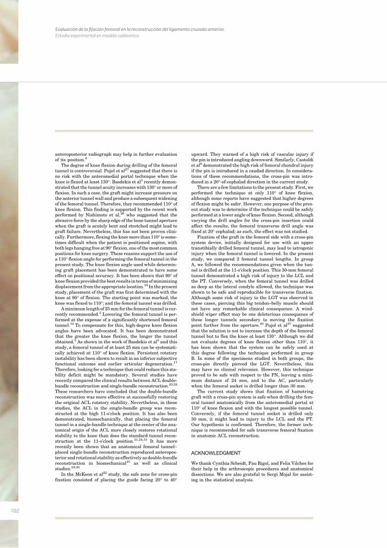
102
Evaluación de la fijación femoral en la reconstrucción del ligamento cruzado anterior. Estudio experimental en modelo cadavérico
anteroposterior radiograph may help in further evaluationof its position.8
The degree of knee flexion during drilling of the femoraltunnel is controversial. Pujol et al27 suggested that there isno risk with the anteromedial portal technique when theknee is flexed at least 130�. Basdekis et al3 recently demon-strated that the tunnel acuity increases with 130� ormore offlexion. In such a case, the graft might increase pressure onthe anterior tunnelwall and produce a subsequentwideningof the femoral tunnel. Therefore, they recommended 110� ofknee flexion. This finding is supported by the recent workperformed by Nishimoto et al,26 who suggested that theabrasive force by the sharp edge of the bone tunnel aperturewhen the graft is acutely bent and stretched might lead tograft failure. Nevertheless, this has not been proven clini-cally. Furthermore, flexing the kneemore than110� is some-times difficult when the patient is positioned supine, withboth legs hanging free at 90� flexion, one of themost commonpositions for knee surgery. These reasons support the use ofa 110� flexion angle for performing the femoral tunnel in thepresent study. The knee flexion angle used while determin-ing graft placement has been demonstrated to have someeffect on positional accuracy. It has been shown that 90� ofknee flexionprovided the best results in terms ofminimizingdisplacement from the appropriate location.16 In the presentstudy, placement of the graft was first determined with theknee at 90� of flexion. The starting point was marked; theknee was flexed to 110�; and the femoral tunnel was drilled.
Aminimum length of 25mm for the femoral tunnel is cur-rently recommended.3 Lowering the femoral tunnel is per-formed at the expense of a significantly shortened femoraltunnel.12 To compensate for this, high-degree knee flexionangles have been advocated. It has been demonstratedthat the greater the knee flexion, the longer the tunnelobtained.3 As shown in the work of Basdekis et al3 and thisstudy, a femoral tunnel of at least 25 mm can be systemati-cally achieved at 110� of knee flexion. Persistent rotatoryinstability has been shown to result in an inferior subjectivefunctional outcome and earlier articular degeneration.17
Therefore, looking for a technique that could reduce this sta-bility deficit might be mandatory. Several studies haverecently compared the clinical results between ACL double-bundle reconstruction and single-bundle reconstruction.23,32
These researchers have concluded that the double-bundlereconstruction was more effective at successfully restoringthe original ACL rotatory stability. Nevertheless, in thesestudies, the ACL in the single-bundle group was recon-structed at the high 11-o’clock position. It has also beendemonstrated, biomechanically, that placing the femoraltunnel in a single-bundle technique at the center of the ana-tomical origin of the ACL more closely restores rotationalstability to the knee than does the standard tunnel recon-struction at the 11-o’clock position.21,24,31 It has morerecently been shown that an anatomical femoral tunnel–placed single-bundle reconstruction reproduced anteropos-terior and rotational stability as effectively asdouble-bundlereconstruction in biomechanical15 as well as clinicalstudies.19,30
In the McKeon et al22 study, the safe zone for cross-pinfixation consisted of placing the guide facing 20� to 40�
upward. They warned of a high risk of vascular injury ifthe pin is introduced angling downward. Similarly, Castoldiet al6 demonstrated the high risk of femoral chondral injuryif the pin is introduced in a caudad direction. In considera-tions of these recommendations, the cross-pin was intro-duced in a 20�-of-cephalad direction in the current study.
There are a few limitations to the present study. First, weperformed the technique at only 110� of knee flexion,although some reports have suggested that higher degreesof flexion might be safer. However, one purpose of the pres-ent study was to determine if the technique could be safelyperformed at a lower angle of knee flexion. Second, althoughvarying the drill angles for the cross-pin insertion couldaffect the results, the femoral transverse drill angle wasfixed at 20� cephalad; as such, the effect was not studied.
Fixation of the graft in the femoral side with a cross-pinsystem device, initially designed for use with an uppertranstibially drilled femoral tunnel, may lead to iatrogenicinjury when the femoral tunnel is lowered. In the presentstudy, we compared 2 femoral tunnel lengths. In groupA, we followed the recommendations given when the tun-nel is drilled at the 11-o’clock position. This 30-mm femoraltunnel demonstrated a high risk of injury to the LCL andthe PT. Conversely, when the femoral tunnel was drilledas deep as the lateral condyle allowed, the technique wasshown to be safe and reproducible for transverse fixation.Although some risk of injury to the LGT was observed inthese cases, piercing this big tendon–belly muscle shouldnot have any remarkable clinical consequence. A wind-shield wiper effect may be one deleterious consequence ofthese longer tunnels secondary to moving the fixationpoint further from the aperture.20 Pujol et al27 suggestedthat the solution is not to increase the depth of the femoraltunnel but to flex the knee at least 130�. Although we didnot evaluate degrees of knee flexion other than 110�, ithas been shown that the system can be safely used atthis degree following the technique performed in groupB. In some of the specimens studied in both groups, thecross-pin directly pierced the LGT. Nevertheless, thismay have no clinical relevance. However, this techniqueproved to be safe with respect to the PN, leaving a mini-mum distance of 24 mm, and to the AC, particularlywhen the femoral socket is drilled longer than 30 mm.
The current study shows that fixation of hamstringgraft with a cross-pin system is safe when drilling the fem-oral tunnel anatomically from the anteromedial portal at110� of knee flexion and with the longest possible tunnel.Conversely, if the femoral tunnel socket is drilled only30 mm, it might lead to injury to the LCL and the PT.Our hypothesis is confirmed. Therefore, the former tech-nique is recommended for safe transverse femoral fixationin anatomic ACL reconstruction.
ACKNOWLEDGMENT
We thank Cynthia Scheidt, Pau Rigol, and Felix Vilches fortheir help in the arthroscopic procedures and anatomicaldissections. We are also grateful to Sergi Mojal for assist-ing in the statistical analysis.
Vol. 38, No. 9, 2010 Cross-Pin and Anatomic ACL Reconstruction 1883
103
REFERENCES
1. Alburquerque RF, Amatuzzi MM, Pacheco AP, Angelini FJ, Campos
O Jr. Positioning of the femoral tunnel for arthroscopic reconstruction
of the anterior cruciate ligament: comparative study of two techni-
ques. Clinics. 2007;62:613-618.
2. Arnold M P, Kooloos J, van Kampen A. Single-incision technique
misses the anatomical femoral anterior cruciate ligament insertion:
a cadaveric study. Knee Surg Sports Traumatol Arthrosc.
2001;9:194-199.
3. Basdekis G, Abisafi C, Christel P. Influence of knee flexion angle on
femoral tunnel characteristics when drilled through the anteromedial
portal during anterior cruciate ligament reconstruction. Arthroscopy.
2008;24:459-464.
4. Bernard M, Hertel P, Hornung H, Cierpinski T. Femoral insertion of
the ACL: radiographic quadrant method. Am J Knee Surg. 1997;
10:14-21.
5. Bylski-Austrow DI, Grood E, Hefzy M, Holden JP, Butler DL. Anterior
cruciate ligament replacements: a mechanical study of femoral
attachment location, flexion angle at tensioning and initial tension.
J Orthop Res. 1990;8:522-531.
6. Castoldi F, Bonasia DE, Marmotti A, Dettoni F, Rossi R. ACL recon-
struction using the Rigidfix femoral fixation device via the anterome-
dial portal: a cadaver study to evaluate chondral injuries. Knee Surg
Sports Traumatol Arthrosc. 2008;16:275-278.
7. Clark R, Olsen RE, Larson BJ, Goble EM, Farrer RP. Cross-pin fem-
oral fixation: a new technique for hamstring anterior cruciate ligament
reconstruction of the knee. Arthroscopy. 1998;14:258-267.
8. Cole J, Brand JC Jr, Caborn DN, Johnson DL. Radiographic analysis
of femoral tunnel position in anterior cruciate ligament reconstruction.
Am J Knee Surg. 2000;13:218-222.
9. Dargel J, Schmidt-Wiethoff R, Fisher S, Mader K, Koebke J,
Schneider T. Femoral bone tunnel placement using the transtibial
tunnel or the anteromedial portal in ACL reconstruction: a radio-
graphic evaluation. Knee Surg Sports Traumatol Arthrosc. 2009;
17:220-227.
10. Fu FH. The clock-face reference: simple but nonanatomic. Arthros-
copy. 2008;24:1433.
11. Gavriilidis I, Motsis EK, Pakos EE, Georgoulis AD, Mitsionis G, Xena-
kis TA. Transtibial versus anteromedial portal of the femoral tunnel in
ACL reconstruction: a cadaveric study. Knee. 2008;15:364-367.
12. Golish SR, Baumfeld JA, Schoderbek RJ, Miller MD. The effect of
femoral tunnel starting position on tunnel length in anterior cruciate
ligament reconstruction: a cadaveric study. Arthroscopy. 2007;23:
1187-1192.
13. Hantes M, Dailiana Z, Zachos V, Varitimidis S. Anterior cruciate liga-
ment reconstruction using the Bio-Transfix femoral fixation device
and anteromedial portal technique. Knee Surg Sports Traumatol
Arthrosc. 2006;14:497-501.
14. Harner C, Honkamp N, Ranawat AS. Anteromedial portal technique
for creating the anterior cruciate ligament femoral tunnel. Arthros-
copy. 2008;24:113-115.
15. Ho JY, Gardiner A, Shah V, Steiner ME. Equal kinematics between
central anatomic single-bundle and double-bundle anterior cruciate
ligament reconstructions. Arthroscopy. 2009;25:464-472.
16. Hoshino Y, Nagamune K, Yagi M, et al. The effect of intra-operative
knee flexion angle on determination of graft location in the anatomic
double-bundle anterior cruciate ligament reconstruction. Knee Surg
Sports Traumatol Arthrosc. 2009;17:1052-1060.
17. Jonsson H, Riklund-Ahlstrom K, Lind J. Positive pivot shift after ACL
reconstruction predicts later osteoarthrosis: 63 patients followed 5-9
years after surgery. Acta Orthop Scand. 2004;75:594-599.
18. Kanamori A, Woo SL, Ma CB, et al. The forces in the anterior cruciate
ligament and knee kinematics during a simulated pivot shift test:
a human cadaveric study using robotic technology. Arthroscopy.
2000;16:633-639.
19. Kanaya A, Ochi M, Deie M, Adachi N, Nishimori M, Nakamae A. Intra-
operative evaluation of anteroposterior and rotational stabilities in
anterior cruciate ligament reconstruction: lower femoral tunnel
placed single-bundle versus double-bundle reconstruction. Knee
Surg Sports Traumatol Arthrosc. 2009;17:907-913.
20. Kurosaka M, Yoshiya S, Andrish JT. A biomechanical comparison of
different surgical techniques of graft fixation in anterior cruciate liga-
ment reconstruction. Am J Sports Med. 1987;15:225-229.
21. Loh JC, Fukuda Y, Tsuda E, Steadman RJ, Fu FH, Woo SL-Y. Knee
stability and graft function following anterior cruciate ligament recon-
struction: comparison between 11 o’clock and 10 o’clock femoral
tunnel placement. Arthroscopy. 2003;19:297-304.
22. McKeon BP, Gordon M, DeConciliis G, Scheller A. The safe zone for
femoral cross-pin fixation: an anatomical study. J Knee Surg.
2007;20:285-288.
23. Muneta T, Koga H, Mochizuki T, et al: A prospective randomized
study of 4-strand semitendinosus tendon anterior cruciate ligament
reconstruction comparing single-bundle and double-bundle techni-
ques. Arthroscopy. 2007;23:618-628.
24. Musahl V, Plakseychuk A, VanScyoc A, et al. Varying femoral tunnels
between the anatomical footprint and isometric positions: effect on
kinematics of the anterior cruciate ligament-reconstructed knee.
Am J Sports Med. 2005;5:712-718.
25. Nakamura M, Deie M, Shibuya H, et al. Potential risk of femoral tun-
nel drilling through the far anteromedial portal: a cadaveric study.
Arthroscopy. 2009;25:481-487.
26. Nishimoto K, Kuroda R, Mizuno K, et al. Analysis of the graft bending
angle at the femoral tunnel aperture in anatomic double bundle ante-
rior cruciate ligament reconstruction: a comparison of the transtibial
and the far anteromedial portal technique. Knee Surg Sports Trauma-
tol Arthrosc. 2009;17:270-276.
27. Pujol N, Thierry D, Bauer T, Hardy P. Transverse femoral fixation in
anterior cruciate ligament (ACL) reconstruction with hamstrings
grafts: an anatomic study about the relationships between the trans-
condylar device and the posterolateral structures of the knee. Knee
Surg Sports Traumatol Arthrosc. 2006;14:724-729.
28. Robson AW. VI: Ruptured crucial ligaments and their repair by oper-
ation. Ann Surg. 1903;37:716-718.
29. Rue JP, Ghodadra N, Bach BR Jr. Femoral tunnel placement in
single-bundle anterior cruciate ligament reconstruction: a cadaveric
study relating transtibial lateralized femoral tunnel position to the
anteromedial and posterolateral bundle femoral origins of the anterior
cruciate ligament. Am J Sports Med. 2008;36:73-79.
30. Sastre S, Popescu D, Nunez M, Pomes J, Tomas X, Peidro L. Dou-
ble-bundle versus single-bundle ACL reconstruction using the hori-
zontal femoral position: a prospective, randomized study. Knee
Surg Sports Traumatol Arthrosc. 2010;18:32-36.
31. Scopp JM, Jasper LE, Belkoff SM, Moorman CT III. The effect of obli-
que femoral tunnel placement on rotational constraint of the knee
reconstructed using patellar tendon autografts. Arthroscopy.
2004;3:294-299.
32. Siebold R, Dehler C, Ellert T. Prospective randomized comparison of
double-bundle versus single-bundle anterior cruciate ligament recon-
struction. Arthroscopy. 2008;24:137-145.
33. Zantop T, Wellmann M, Fu FH, Petersen W. Tunnel positioning of
anteromedial and posterolateral bundles in anatomic anterior cruci-
ate ligament reconstruction: anatomic and radiographic findings.
Am J Sports Med. 2008;36:65-72.
For reprints and permission queries, please visit SAGE’s Web site at http://www.sagepub.com/journalsPermissions.nav
1884 Gelber et al The American Journal of Sports Medicine
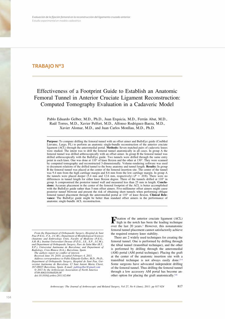
104
Evaluación de la fijación femoral en la reconstrucción del ligamento cruzado anterior. Estudio experimental en modelo cadavérico
TRABAJO Nº3
Effectiveness of a Footprint Guide to Establish an AnatomicFemoral Tunnel in Anterior Cruciate Ligament Reconstruction:
Computed Tomography Evaluation in a Cadaveric Model
Pablo Eduardo Gelber, M.D., Ph.D., Juan Erquicia, M.D., Ferrán Abat, M.D.,Raúl Torres, M.D., Xavier Pelfort, M.D., Alfonso Rodriguez-Baeza, M.D.,
Xavier Alomar, M.D., and Juan Carlos Monllau, M.D., Ph.D.
Purpose: To compare drilling the femoral tunnel with an offset aimer and BullsEye guide (ConMedLinvatec, Largo, FL) to perform an anatomic single-bundle reconstruction of the anterior cruciateligament (ACL) through the anteromedial portal. Methods: Seven matched pairs of cadaveric kneeswere studied. The intent was to drill the femoral tunnel anatomically in all cases. In group A thefemoral tunnel was drilled arthroscopically with an offset aimer. In group B the femoral tunnel wasdrilled arthroscopically with the BullsEye guide. Two tunnels were drilled through the same entrypoint in each knee. One was done at 110° of knee flexion and the other at 130°. They were scannedby computed tomography and reconstructed 3-dimensionally. Volume-rendering software was usedto document relations of the drilled tunnel to the bony anatomy and tunnel length. Results: In groupB the femoral tunnel was placed at the center of the femoral insertion site. The center of the tunnelwas 9.4 mm from the high cartilage margin and 8.6 mm from the low cartilage margin. In group Athe tunnels were placed deeper (5.4 mm and 12.6 mm, respectively) (P � .018). There were nodifferences in tunnel length for either knee flexion degree. Three of the tunnels drilled at 110° ingroup A compromised the posterior tunnel wall and measured less than 25 mm in length. Conclu-sions: Accurate placement in the center of the femoral footprint of the ACL is better accomplishedwith the BullsEye guide rather than 5-mm offset aimers. Five-millimeter offset aimers might causeposterior tunnel blowout and present the risk of obtaining short tunnels when performing obliquefemoral tunnel placement through the anteromedial portal at 110° of knee flexion. Clinical Rele-vance: The BullsEye guide might be better than standard offset aimers in the performance ofanatomic single-bundle ACL reconstruction.
Fixation of the anterior cruciate ligament (ACL)high in the notch has been the leading technique
over the last 20 years.1 However, this nonanatomicfemoral tunnel placement cannot satisfactorily achievethe required rotatory knee stability.
There are 2 widely used techniques for creating thefemoral tunnel. One is performed by drilling throughthe tibial tunnel (transtibial technique), and the otheris performed by drilling through the anteromedial(AM) portal (AM portal technique). Placing the graftat the center of the anatomic insertion site with atranstibial technique is not always easily done.2-4
Some surgeons have advocated independent drillingof the femoral tunnel. Thus drilling the femoral tunnelthrough a low accessory AM portal has become an-other option for placing the graft anatomically.5,6
From the Department of Orthopaedic Surgery, Hospital de SantPau (P.E.G., F.A., J.C.M.), Department of Morphological Sciences(Anatomy and Embryology Unit), Faculty of Medicine (P.E.G.,A.R.-B.), Institut Universitari Dexeus (P.E.G., J.E., X.P., J.C.M.),and Department of Orthopaedic Surgery, Parc de Salut Mar (R.T.,X.P.), Universitat Autònoma de Barcelona; and Department ofRadiology, Creu Blanca (X.A.), Barcelona, Spain.
The authors report no conflict of interest.Received June 19, 2010; accepted February 4, 2011.Address correspondence to Pablo Eduardo Gelber, M.D., Ph.D.,
Department of Orthopaedic Surgery, Hospital de Sant Pau, Uni-versitat Autònoma de Barcelona. C/ Sant Antoni Maria Claret,167-08025 Barcelona, Spain. E-mail: [email protected]
© 2011 by the Arthroscopy Association of North America0749-8063/10364/$36.00doi:10.1016/j.arthro.2011.02.004
817Arthroscopy: The Journal of Arthroscopic and Related Surgery, Vol 27, No 6 (June), 2011: pp 817-824
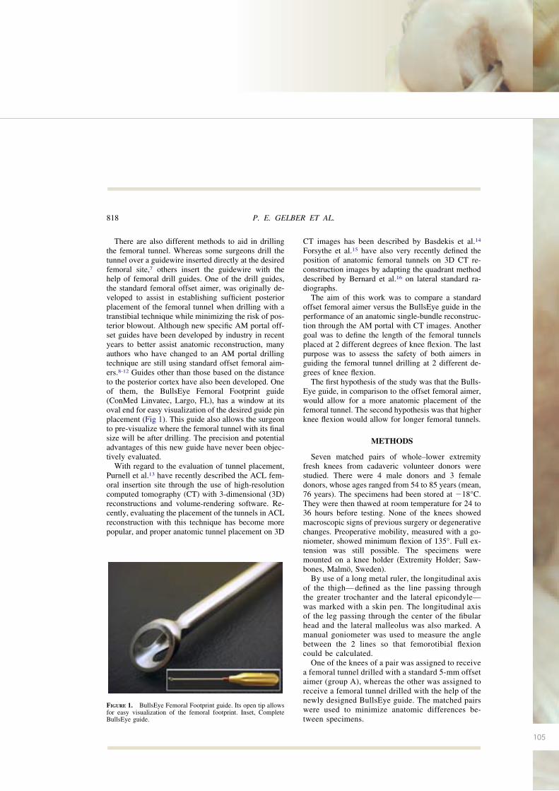
105
There are also different methods to aid in drillingthe femoral tunnel. Whereas some surgeons drill thetunnel over a guidewire inserted directly at the desiredfemoral site,7 others insert the guidewire with thehelp of femoral drill guides. One of the drill guides,the standard femoral offset aimer, was originally de-veloped to assist in establishing sufficient posteriorplacement of the femoral tunnel when drilling with atranstibial technique while minimizing the risk of pos-terior blowout. Although new specific AM portal off-set guides have been developed by industry in recentyears to better assist anatomic reconstruction, manyauthors who have changed to an AM portal drillingtechnique are still using standard offset femoral aim-ers.8-12 Guides other than those based on the distanceto the posterior cortex have also been developed. Oneof them, the BullsEye Femoral Footprint guide(ConMed Linvatec, Largo, FL), has a window at itsoval end for easy visualization of the desired guide pinplacement (Fig 1). This guide also allows the surgeonto pre-visualize where the femoral tunnel with its finalsize will be after drilling. The precision and potentialadvantages of this new guide have never been objec-tively evaluated.
With regard to the evaluation of tunnel placement,Purnell et al.13 have recently described the ACL fem-oral insertion site through the use of high-resolutioncomputed tomography (CT) with 3-dimensional (3D)reconstructions and volume-rendering software. Re-cently, evaluating the placement of the tunnels in ACLreconstruction with this technique has become morepopular, and proper anatomic tunnel placement on 3D
CT images has been described by Basdekis et al.14
Forsythe et al.15 have also very recently defined theposition of anatomic femoral tunnels on 3D CT re-construction images by adapting the quadrant methoddescribed by Bernard et al.16 on lateral standard ra-diographs.
The aim of this work was to compare a standardoffset femoral aimer versus the BullsEye guide in theperformance of an anatomic single-bundle reconstruc-tion through the AM portal with CT images. Anothergoal was to define the length of the femoral tunnelsplaced at 2 different degrees of knee flexion. The lastpurpose was to assess the safety of both aimers inguiding the femoral tunnel drilling at 2 different de-grees of knee flexion.
The first hypothesis of the study was that the Bulls-Eye guide, in comparison to the offset femoral aimer,would allow for a more anatomic placement of thefemoral tunnel. The second hypothesis was that higherknee flexion would allow for longer femoral tunnels.
METHODS
Seven matched pairs of whole–lower extremityfresh knees from cadaveric volunteer donors werestudied. There were 4 male donors and 3 femaledonors, whose ages ranged from 54 to 85 years (mean,76 years). The specimens had been stored at �18°C.They were then thawed at room temperature for 24 to36 hours before testing. None of the knees showedmacroscopic signs of previous surgery or degenerativechanges. Preoperative mobility, measured with a go-niometer, showed minimum flexion of 135°. Full ex-tension was still possible. The specimens weremounted on a knee holder (Extremity Holder; Saw-bones, Malmö, Sweden).
By use of a long metal ruler, the longitudinal axisof the thigh— defined as the line passing throughthe greater trochanter and the lateral epicondyle—was marked with a skin pen. The longitudinal axisof the leg passing through the center of the fibularhead and the lateral malleolus was also marked. Amanual goniometer was used to measure the anglebetween the 2 lines so that femorotibial flexioncould be calculated.
One of the knees of a pair was assigned to receivea femoral tunnel drilled with a standard 5-mm offsetaimer (group A), whereas the other was assigned toreceive a femoral tunnel drilled with the help of thenewly designed BullsEye guide. The matched pairswere used to minimize anatomic differences be-tween specimens.
FIGURE 1. BullsEye Femoral Footprint guide. Its open tip allowsfor easy visualization of the femoral footprint. Inset, CompleteBullsEye guide.
818 P. E. GELBER ET AL.
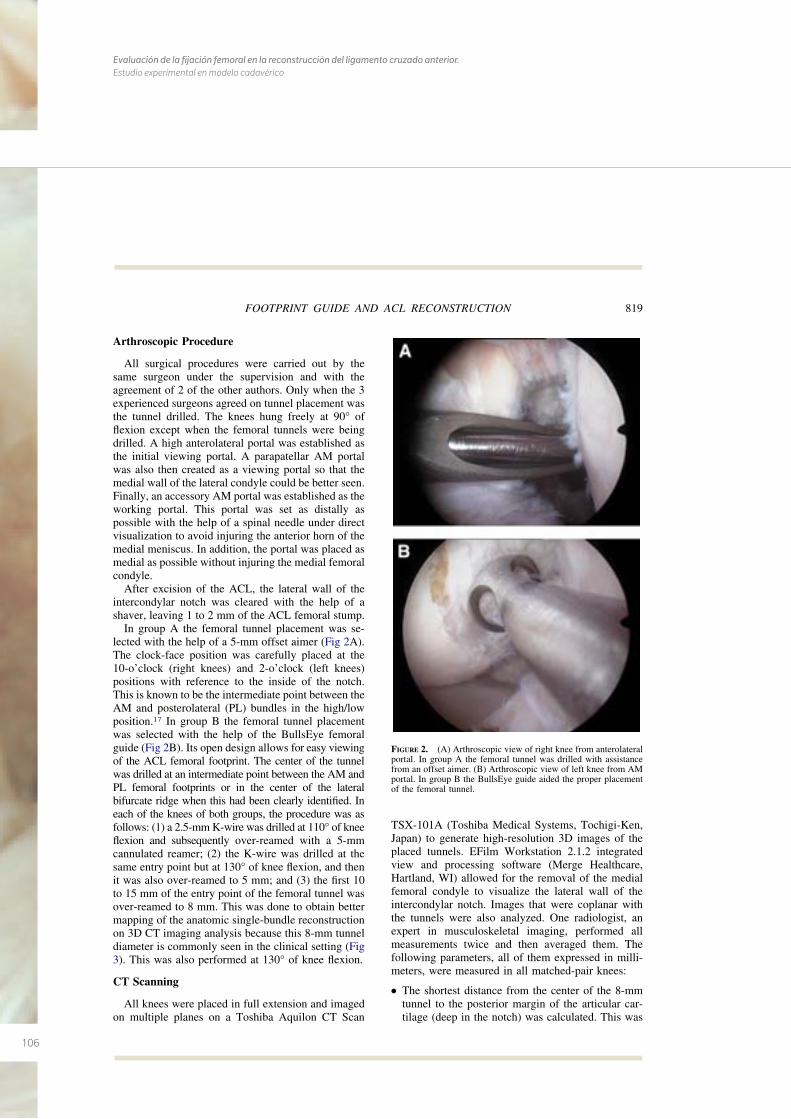
106
Evaluación de la fijación femoral en la reconstrucción del ligamento cruzado anterior. Estudio experimental en modelo cadavérico
Arthroscopic Procedure
All surgical procedures were carried out by thesame surgeon under the supervision and with theagreement of 2 of the other authors. Only when the 3experienced surgeons agreed on tunnel placement wasthe tunnel drilled. The knees hung freely at 90° offlexion except when the femoral tunnels were beingdrilled. A high anterolateral portal was established asthe initial viewing portal. A parapatellar AM portalwas also then created as a viewing portal so that themedial wall of the lateral condyle could be better seen.Finally, an accessory AM portal was established as theworking portal. This portal was set as distally aspossible with the help of a spinal needle under directvisualization to avoid injuring the anterior horn of themedial meniscus. In addition, the portal was placed asmedial as possible without injuring the medial femoralcondyle.
After excision of the ACL, the lateral wall of theintercondylar notch was cleared with the help of ashaver, leaving 1 to 2 mm of the ACL femoral stump.
In group A the femoral tunnel placement was se-lected with the help of a 5-mm offset aimer (Fig 2A).The clock-face position was carefully placed at the10-o’clock (right knees) and 2-o’clock (left knees)positions with reference to the inside of the notch.This is known to be the intermediate point between theAM and posterolateral (PL) bundles in the high/lowposition.17 In group B the femoral tunnel placementwas selected with the help of the BullsEye femoralguide (Fig 2B). Its open design allows for easy viewingof the ACL femoral footprint. The center of the tunnelwas drilled at an intermediate point between the AM andPL femoral footprints or in the center of the lateralbifurcate ridge when this had been clearly identified. Ineach of the knees of both groups, the procedure was asfollows: (1) a 2.5-mm K-wire was drilled at 110° of kneeflexion and subsequently over-reamed with a 5-mmcannulated reamer; (2) the K-wire was drilled at thesame entry point but at 130° of knee flexion, and thenit was also over-reamed to 5 mm; and (3) the first 10to 15 mm of the entry point of the femoral tunnel wasover-reamed to 8 mm. This was done to obtain bettermapping of the anatomic single-bundle reconstructionon 3D CT imaging analysis because this 8-mm tunneldiameter is commonly seen in the clinical setting (Fig3). This was also performed at 130° of knee flexion.
CT Scanning
All knees were placed in full extension and imagedon multiple planes on a Toshiba Aquilon CT Scan
TSX-101A (Toshiba Medical Systems, Tochigi-Ken,Japan) to generate high-resolution 3D images of theplaced tunnels. EFilm Workstation 2.1.2 integratedview and processing software (Merge Healthcare,Hartland, WI) allowed for the removal of the medialfemoral condyle to visualize the lateral wall of theintercondylar notch. Images that were coplanar withthe tunnels were also analyzed. One radiologist, anexpert in musculoskeletal imaging, performed allmeasurements twice and then averaged them. Thefollowing parameters, all of them expressed in milli-meters, were measured in all matched-pair knees:
● The shortest distance from the center of the 8-mmtunnel to the posterior margin of the articular car-tilage (deep in the notch) was calculated. This was
FIGURE 2. (A) Arthroscopic view of right knee from anterolateralportal. In group A the femoral tunnel was drilled with assistancefrom an offset aimer. (B) Arthroscopic view of left knee from AMportal. In group B the BullsEye guide aided the proper placementof the femoral tunnel.
819FOOTPRINT GUIDE AND ACL RECONSTRUCTION
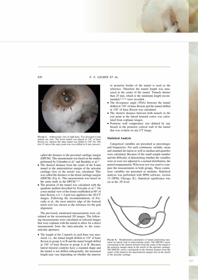
107
called the distance to the proximal cartilage margin(DPCM). This measurement was based on the studiesperformed by Colombet et al.2 and Basdekis et al.14
● The shortest distance from the center of the 8-mmtunnel to the anteroinferior margin of the articularcartilage (low in the notch) was calculated. Thiswas called the distance to the distal cartilage margin(DDCM) (Fig 4). This measurement was based onthe same study as the DPCM.2,14
● The position of the tunnel was calculated with thequadrant method described by Forsythe et al.15 Ona true medial view of the femur established at 90° ofknee flexion, a 4 � 4 grid was applied to the 3D CTimages. Following the recommendations of For-sythe et al., the most anterior edge of the femoralnotch roof was chosen as the reference for the gridalignment.
The previously mentioned measurements were cal-culated on the reconstructed 3D images. The follow-ing measurements were calculated on selected imagesthat were coplanar with the tunnel to allow for a directmeasurement from the intra-articular to the extra-articular apertures:
● The length of the 2 tunnels in each knee was mea-sured, i.e., the tunnel length drilled at 110° of kneeflexion in group A or B and the tunnel length drilledat 130° of knee flexion in group A or B. Becauselateral femoral condyles have a rounded shape andthe tunnel is not drilled orthogonally, the measuredlength may vary depending on whether the anterior
or posterior border of the tunnel is used as thereference. Therefore the tunnel length was mea-sured in the center of the tunnel. Tunnels shorterthan 25 mm, which is the minimum length recom-mended,9,10,18 were recorded.
● The divergence angle (TDA) between the tunneldrilled at 110° of knee flexion and the tunnel drilledat 130° of knee flexion was calculated.
● The shortest distance between both tunnels in theexit point at the lateral femoral cortex was calcu-lated from coplanar images.
● Posterior wall compromise was defined by anybreach in the posterior cortical wall of the tunnelthat was evident on any CT image.
Statistical Analysis
Categorical variables are presented as percentagesand frequencies. For each continuous variable, meanand standard deviation as well as median and quartileswere calculated. Because of the small sample numberand the difficulty of determining whether the variableswere or were not adjusted to a normal distribution, thepaired nonparametric Wilcoxon test was used to com-pare the measurements in both groups. These contin-uous variables are presented as medians. Statisticalanalysis was performed with SPSS software, version15 (SPSS, Chicago, IL). Statistical significance wasset at the .05 level.
FIGURE 4. Morphometric parameters of tunnel positioning mea-sured on lateral wall of intercondylar notch. The DPCM’s arrowcorresponds to the shortest distance from the center of the tunnel tothe posterior margin (deep in the notch) of the articular cartilage.The DDCM’s arrow corresponds to the shortest distance from thecenter of the tunnel to the anteroinferior margin (low in the notch)of the articular cartilage.
FIGURE 3. Arthroscopic view of right knee. Two divergent 5-mmtunnels are seen. The lower tunnel was placed at 110° of kneeflexion (a), whereas the other tunnel was drilled at 130° (b). Thefirst 15 mm of the entry point was over-drilled to 8 mm (arrows).
820 P. E. GELBER ET AL.
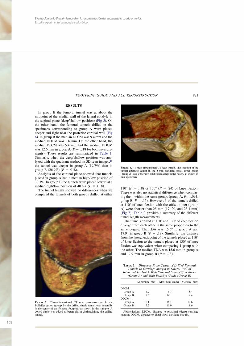
108
Evaluación de la fijación femoral en la reconstrucción del ligamento cruzado anterior. Estudio experimental en modelo cadavérico
RESULTS
In group B the femoral tunnel was at about themidpoint of the medial wall of the lateral condyle inthe sagittal plane (deep/shallow position) (Fig 5). Onthe other hand, the femoral tunnels drilled in thespecimens corresponding to group A were placeddeeper and right near the posterior cortical wall (Fig6). In group B the median DPCM was 9.4 mm and themedian DDCM was 8.6 mm. On the other hand, themedian DPCM was 5.4 mm and the median DDCMwas 12.6 mm in group A (P � .018 for both measure-ments). These results are summarized in Table 1.Similarly, when the deep/shallow position was ana-lyzed with the quadrant method on 3D scan images,15
the tunnel was deeper in group A (19.7%) than ingroup B (26.9%) (P � .018).
Analysis of the coronal plane showed that tunnelsplaced in group A had a median high/low position of30.3%. In group B the tunnels were placed lower, at amedian high/low position of 40.8% (P � .018).
The tunnel length showed no differences when wecompared the tunnels of both groups drilled at either
110° (P � .18) or 130° (P � .24) of knee flexion.There was also no statistical difference when compar-ing them within the same groups (group A, P � .091;group B, P � .15). However, 3 of the tunnels drilledat 110° of knee flexion with the offset aimer (groupA) were shorter than 25 mm (17, 20, and 23.1 mm)(Fig 7). Table 2 provides a summary of the differenttunnel length measurements.
The tunnels drilled at 110° and 130° of knee flexiondiverge from each other in the same proportion to thesame degree. The TDA was 15.6° in group A and17.9° in group B (P � .18). Similarly, the distancefrom the lateral exit point of the tunnels placed at 110°of knee flexion to the tunnels placed at 130° of kneeflexion was equivalent when comparing 1 group withthe other. The median TDA was 15.6 mm in group Aand 17.9 mm in group B (P � .73).
FIGURE 5. Three-dimensional CT scan reconstruction. In theBullsEye group (group B), the drilled single tunnel was generallyin the center of the femoral footprint, as shown in this sample. Adotted circle was added to better aid in distinguishing the drilledtunnel.
FIGURE 6. Three-dimensional CT scan image. The location of thetunnel aperture center in the 5-mm standard offset aimer group(group A) was generally established deep in the notch, as shown inthis specimen.
TABLE 1. Distances From Center of Drilled FemoralTunnels to Cartilage Margin in Lateral Wall of
Intercondylar Notch With Standard 5-mm Offset Aimer(Group A) and With BullsEye Guide (Group B)
Minimum (mm) Maximum (mm) Median (mm)
DPCMGroup A 4.7 6.7 5.4Group B 8.5 14 9.4
DDCMGroup A 10.1 16.1 12.6Group B 7.2 10.9 8.6
Abbreviations: DPCM, distance to proximal (deep) cartilagemargin; DDCM, distance to distal (low) cartilage margin.
821FOOTPRINT GUIDE AND ACL RECONSTRUCTION
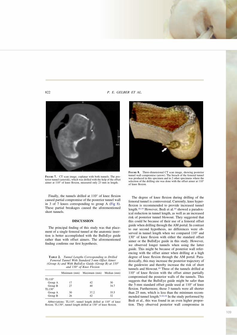
109
Finally, the tunnels drilled at 110° of knee flexioncaused partial compromise of the posterior tunnel wallin 3 of 7 knees corresponding to group A (Fig 8).These partial breakages caused the aforementionedshort tunnels.
DISCUSSION
The principal finding of this study was that place-ment of a single femoral tunnel at the anatomic inser-tion is better accomplished with the BullsEye guiderather than with offset aimers. The aforementionedfinding confirms our first hypothesis.
The degree of knee flexion during drilling of thefemoral tunnel is controversial. Currently, knee hyper-flexion is recommended to provide increased tunnellength.18,19 However, Bedi et al.10 showed a paradox-ical reduction in tunnel length, as well as an increasedrisk of posterior tunnel blowout. They suggested thatthis could be because of their use of a femoral offsetguide when drilling through the AM portal. In contrastto our second hypothesis, no differences were ob-served in tunnel length when we compared 110° and130° of knee flexion with either the standard offsetaimer or the BullsEye guide in this study. However,we observed longer tunnels when using the latterguide. This might be because of posterior wall refer-encing with the offset aimer when drilling at a highdegree of knee flexion through the AM portal. Para-doxically, this may increase the posterior trajectory ofthe guidewire and thereby increase the risk of shorttunnels and blowout.10 Three of the tunnels drilled at110° of knee flexion with the offset aimer partiallycompromised the posterior walls of the tunnels. Thissuggests that the BullsEye guide might be safer thanthe 5-mm standard offset guide used at 110° of kneeflexion. Furthermore, those 3 tunnels were all shorterthan 25 mm, which is less than the minimum recom-mended tunnel length.9,10,18 In the study performed byBedi et al., this was found in an even higher propor-tion. They observed posterior wall compromise in
FIGURE 7. CT scan image, coplanar with both tunnels. The pos-terior tunnel (asterisk), which was drilled with the help of the offsetaimer at 110° of knee flexion, measured only 23 mm in length.
TABLE 2. Tunnel Lengths Corresponding to DrilledFemoral Tunnel With Standard 5-mm Offset Aimer
(Group A) and With BullsEye Guide (Group B) at 110°and 130° of Knee Flexion
Minimum (mm) Maximum (mm) Median (mm)
TL110°Group A 17 42 30Group B 27 40 34.7
TL130°Group A 30 37.2 35.5Group B 26 42 32
Abbreviations: TL110°, tunnel length drilled at 110° of kneeflexion; TL130°, tunnel length drilled at 130° of knee flexion.
FIGURE 8. Three-dimensional CT scan image, showing posteriortunnel wall compromise (arrow). The breach of the femoral tunnelwas produced in this specimen and in 2 other specimens where theselection of the drilling site was done with the offset aimer at 110°of knee flexion.
822 P. E. GELBER ET AL.
110
Evaluación de la fijación femoral en la reconstrucción del ligamento cruzado anterior. Estudio experimental en modelo cadavérico
75% of the tunnels placed at 120° of knee flexion, allof which had a mean length of 21.3 mm.
Persistent rotatory instability has been shown toresult in an inferior subjective functional outcome andearlier articular degeneration.20 Therefore looking fora technique that could reduce this stability deficitshould be mandatory. Several studies have recentlyshown, biomechanically, that placing the femoral tun-nel through a single-bundle technique at the center ofthe anatomic origin of the ACL more closely restoresrotational stability to the knee than does the standardtunnel reconstruction high and deep in the notch, nearthe so-called over-the-top position.21-23 In an attemptto approach the anatomic femoral insertion of theACL, some surgeons have suggested lowering thefemoral offset aimers8-12 from the high- and deep-in-the-notch position that is commonly used with thetranstibial technique. This is better accomplished bydrilling the tunnel through the AM portal.3-5 However,to reach the anatomic center of the ACL femoralfootprint, not only a lower but also a shallower tunnelis necessary.2 In this study high-resolution CT with3D reconstruction and volume-rendering softwarewere used to evaluate the femoral tunnel placement.This technique allows for multiplanar visualization ofthe acquired image and the removal of tissue asneeded to allow for measurements of the desired struc-tures and their relations to each other. Purnell et al.13
have recently described the ACL femoral insertion siteusing the same technique. They showed that, on thelateral femoral condyle, the posterior fibers of theACL ended 3.5 mm from the proximal articular car-tilage margin whereas the anteroinferior fibers did soat 3 mm to the distal cartilage margin. In the studyperformed by Basdekis et al.,14 similar results wereobserved. The most posterior fibers of the ACL ended1.6 mm from the articular margin, and the most distalfibers ended 2.2 mm from the articular margin. Theyalso showed that for an ACL double-bundle recon-struction to be considered anatomic, it must showsimilar results. In this case the posterior border of theAM tunnel has to be used for referencing with theproximal cartilage margin and the anteroinferior bor-der of the PL tunnel for the distal cartilage margin.This was also in agreement with the study performedby Girgis et al.24 in 44 dissected cadaveric knees. Intheir study the mean distance from the posteriorfibers of the ACL to the articular surface of thefemoral condyle was 4 mm. In our study the singletunnel placed with the BullsEye guide showed acomparable position to all the aforementioned stud-ies. They all showed similar distances to the prox-
imal as well to the distal cartilage margin. Con-versely, when the tunnel was placed with the help ofthe femoral offset guide, we obtained 1 tunnel thatwas deeper than the anatomic footprint center. For-sythe et al.15 have recently described the position ofthe AM and PL bundles on 3D CT reconstructionimages by adapting the radiographic quadrantmethod described earlier.16 They have shown that ithas high levels of intraobserver and interobserverreliability. They observed mean deep/shallow posi-tions of the AM and PL bundles of 21.7% and35.1%, respectively, and mean high/low positionsof the AM and PL bundles of 33.2% and 55.3%,respectively. In our study the single-tunnel place-ment with the offset aimer was performed at amedian of 19.7% and 30.3% for the deep/shallowand high/low positions, respectively. This was verysimilar to the AM bundle position described in thework of Forsythe et al. On the other hand, thesingle-tunnel placement with the BullsEye guidewas performed at a median of 26.9% and 40.8% forthe deep/shallow and high/low positions, respec-tively. This corresponded to an intermediate posi-tion between both the AM and PL bundles. In thissense, the experimental work performed by Kato etal.,25 which has shown that placing the femoraltunnel in the middle of the femoral footprint repro-duces the in situ force of the normal ACL betterthan any other single-bundle ACL reconstruction, isinteresting. For that reason and according to thespecific placement results observed in our study,performing femoral tunnel placement with theBullsEye guide rather than with offset aimers mightbetter restore the normal kinematics of the knee.
There are some limitations to this study. Some ofthe non–statistically significant differences observedmight be because of the small sample size, which is acommon limitation in cadaveric studies. We did notperform an a priori sample analysis. This may bebecause no differences were observed in tunnel lengthwhen comparing the 2 techniques evaluated and the 2different degrees of knee flexion. However, compar-ing knees from the same cadaver theoretically mini-mizes size differences. Second, only the 8-mm Bulls-Eye guide was compared with 5-mm offset aimers.Higher offset aimers could logically move the drilledtunnel closer to the anatomic site. However, we willstill be using the same fixed distance from the poste-rior wall instead of looking for the specific anatomiccenter in each knee. Finally, neither interobserver norintraobserver reliability was calculated for the mea-surements.
823FOOTPRINT GUIDE AND ACL RECONSTRUCTION
111
CONCLUSIONS
Accurate placement at the center of the femoralfootprint of the ACL is better accomplished with theBullsEye guide rather than with standard 5-mm offsetaimers. Five-millimeter offset aimers might causeposterior tunnel blowout and present the risk of ob-taining short tunnels when performing oblique femo-ral tunnel placement through the AM portal at 110° ofknee flexion.
Acknowledgment: The authors appreciate Esther Moyaand Ignasio Cardona for their help with the arthroscopicprocedures and Manel Querol for his special contribution ofpreparing the specimens. They are also grateful to SergiMojal for assisting in the statistical analysis. Finally, theythank Eric Goode for his help in correcting the manuscript.
REFERENCES
1. Bylski-Austrow DI, Grood E, Hefzy M, Holden JP, Butler DL.Anterior cruciate ligament replacements: A mechanical studyof femoral attachment location, flexion angle at tensioning andinitial tension. J Orthop Res 1990;8:522-532.
2. Colombet P, Robinson J, Christel P, et al. Morphology ofanterior cruciate ligament attachments for anatomic recon-struction: A cadaveric dissection and radiographic study. Ar-throscopy 2006;22:984-992.
3. Alburquerque RF, Amatuzzi MM, Pacheco AP, Angelini FJ,Campos O Jr. Positioning of the femoral tunnel for ar-throscopic reconstruction of the anterior cruciate ligament:Comparative study of 2 techniques. Clin Sao Paulo Brazil2007;62:613-618.
4. Arnold MP, Kooloos J, van Kampen A. Single-incision tech-nique misses the anatomical femoral anterior cruciate ligamentinsertion: A cadaveric study. Knee Surg Sports TraumatolArthrosc 2001;9:194-199.
5. Gavriilidis I, Motsis EK, Pakos EE, Georgoulis AD, MitsionisG, Xenakis TA. Transtibial versus anteromedial portal of thefemoral tunnel in ACL reconstruction: A cadaveric study.Knee 2008;15:364-367.
6. Harner C, Honkamp N, Ranawat AS. Anteromedial portaltechnique for creating the anterior cruciate ligament femoraltunnel. Arthroscopy 2008;24:113-115.
7. Cha PS, Brucker PU, West RV, et al. Arthroscopic double-bundle anterior cruciate ligament reconstruction: An anatomicapproach. Arthroscopy 2005;21:1275-1277.
8. Gelber PE, Reina F, Torres R, Pelfort X, Tey M, Monllau JC.Anatomic single-bundle anterior cruciate ligament reconstruc-tion from the anteromedial portal: Evaluation of transversefemoral fixation in a cadaveric model. Arthroscopy 2010;26:651-657.
9. Gelber PE, Torres R, Reina F, Monllau JC. Effect of femoraltunnel length on the safety of anterior cruciate ligament graftfixation using cross-pin technique: A cadaveric study. Am JSports Med 2010;38:1877-1884.
10. Bedi A, Raphael B, Maderazo A, et al. Drilling for anteriorcruciate ligament reconstruction: A cadaveric study of femoraltunnel length and obliquity. Arthroscopy 2010;26:342-350.
11. Sastre S, Popescu D, Núñez M, Pomes J, Tomas X, Peidro L.Double-bundle versus single-bundle ACL reconstruction usingthe horizontal femoral position: A prospective, randomizedstudy. Knee Surg Sports Traumatol Arthrosc 2010;18:32-36.
12. Yasuda K, Kondo E, Ichiyama H, et al. Anatomic reconstruc-tion of the anteromedial and posterolateral bundles of theanterior cruciate ligament using hamstring tendon grafts. Ar-throscopy 2004;20:1015-1025.
13. Purnell ML, Larson AE, Clancy W. Anterior cruciate ligamentinsertions on the tibia and femur and their relationships tocritical bony landmarks using high-resolution volume-render-ing computed tomography. Am J Sports Med 2008;36:2083-2090.
14. Basdekis G, Christel P, Anne F. Validation of the position ofthe femoral tunnels in anatomic double-bundle ACL recon-struction with 3-D CT scan. Knee Surg Sports TraumatolArthrosc 2009;17:1089-1094.
15. Forsythe B, Kopf S, Wong AK, et al. The location of femoraland tibial tunnels in anatomic anterior cruciate ligament re-construction analyzed by three-dimensional computed tomog-raphy models. J Bone Join Surg Am 2010;92:1418-1426.
16. Bernard M, Hertel P, Hornung H, Cierpinski T. Femoralinsertion of the ACL. Radiographic quadrant method. Am JKnee Surg 1997;10:14-21; discussion, 21-22.
17. Rue JP, Ghodadra N, Bach BR Jr. Femoral tunnel placement insingle-bundle anterior cruciate ligament reconstruction: A ca-daveric study relating transtibial lateralized femoral tunnelposition to the anteromedial and posterolateral bundle femoralorigins of the anterior cruciate ligament. Am J Sports Med2008;36:73-79.
18. Basdekis G, Abisafi C, Christel P. Influence of knee flexionangle on femoral tunnel characteristics when drilled throughthe anteromedial portal during anterior cruciate ligament re-construction. Arthroscopy 2008;4:459-464.
19. Pujol N, Thierry D, Bauer T, Hardy P. Transverse femoralfixation in anterior cruciate ligament (ACL) reconstructionwith hamstrings grafts: An anatomic study about the relation-ships between the transcondylar device and the posterolateralstructures of the knee. Knee Surg Sports Traumatol Arthrosc2006;14:724-729.
20. Jonsson H, Riklund-Ahlström K, Lind J. Positive pivot shiftafter ACL reconstruction predicts later osteoarthrosis. 63 pa-tients followed 5-9 years after surgery. Acta Orthop Scand2004;75:594-599.
21. Loh JC, Fukuda Y, Tsuda E, Steadman RJ, Fu FH, Woo SL-Y.Knee stability and graft function following anterior cruciateligament reconstruction: Comparison between 11 o’clock and10 o’clock femoral tunnel placement. Arthroscopy 2003;3:297-304.
22. Musahl V, Plakseychuk A, VanScyoc A, et al. Varying fem-oral tunnels between the anatomical footprint and isometricpositions. Effect on kinematics of the anterior cruciate liga-ment-reconstructed knee. Am J Sports Med 2005;5:712-718.
23. Scopp JM, Jasper LE, Belkoff SM, Moorman CT III. Theeffect of oblique femoral tunnel placement on rotational con-straint of the knee reconstructed using patellar tendon au-tografts. Arthroscopy 2004;3:294-299.
24. Girgis FG, Marshall JL, Monajem ARS. The cruciate liga-ments of the knee joint: Anatomical, functional, and experi-mental analysis. Clin Orthop Relat Res 1975:216–231.
25. Kato Y, Ingham JM, Fu FH. Effect of tunnel position foranatomic single-bundle ACL reconstruction on knee biome-chanics in a porcine model. Knee Surg Sports TraumatolArthrosc 2010;18:2-10.
824 P. E. GELBER ET AL.

112
Evaluación de la fijación femoral en la reconstrucción del ligamento cruzado anterior. Estudio experimental en modelo cadavérico

113113
B I B L I O G R A F Í A
7. BIBLIOGRAFÍA
114
Evaluación de la fijación femoral en la reconstrucción del ligamento cruzado anterior. Estudio experimental en modelo cadavérico

115
1. Bircher E. Die Arthoroendoskopie. Zentralbl Chir 1921; 48; 1460-1461.
2. Wilk RM, Richmond JC. Dacron ligament reconstruction for chronic anterior cruciata liga-
ment insufficiency. Am J Sports Med. 1993;21:374-9.
3. Ritchey SJ. Ligamentous disruption of the knee. A review with analysis of 28 cases. US Ar-
med Forces Med J. 1960; 11:167-76.
4. Battle WH. A case after open section of the knee-joint for irreducible traumatic dislocation.
Trans Clin Soc Lond. 1900;33: 232-3.
5. Mayo Robson AW. Ruptured crucial ligaments and their repair by operation. Ann Surg.
1903;37:716-8.
6. Hey Groves EW. Operation for the repair of crucial ligaments. Lancet. 1917;190:674-5.
7. Sánchez-Alonso V, Monllau JC. The ACL-Deficient Knee. An approach based on problems
resolution. Springer. 2012.
8. Petersen W, Tillman B. Structure and vascularization of the cruciata ligaments of the hu-
man knee joint. Anat Embryol (Berl). 1999 Sep; 200(3): 325-34.
9. Tena-Arregui J, Barrio-Asensio C, Viejo-Tirado F, Puerta-Fonollá J, Murillo-González J. Ar-
throscopic study of the knee joint in fetuses. Arthoscopy 2003 Oct; 19(8): 862-8.
10. Insall J, Scott WN. Surgery of the knee. 3rd edition. Churchill/Livingston. 2001.
11. Odensen M, Guillquist J. Functional anatomy of the anterior cruciate ligament and a rota-
tionale for reconstruction. J Bone Joint Surg Am. 1985 Feb; 67(2): 257-62.
12. Girgis FG, Marshall JL, Monajem A. The cruciate ligaments of the knee joint. Anatomical,
functional and experimental analysis. Clin Orthop Relat Res 1975 Jan-Feb; (106): 216-31.
13. Morgan CD, Kalman VR, Grawl DM. Definitive landmarks for reproducible tibial tunnel place-
ment in anterior cruciate ligament reconstruction. Arthroscopy. 1995 Jun; 11(3): 275-88.
7. BIBLIOGRAFÍA
116
Evaluación de la fijación femoral en la reconstrucción del ligamento cruzado anterior. Estudio experimental en modelo cadavérico
14. Amiss AA, Dawkins GP. Functional anatomy of the anterior cruciate ligament. Fibre bund-
le actions related to ligament replacements and injuries. J Bone Joint Surg Br. 1991 Mar;
73(2): 260-7.
15. Petersen W, Zantop T. Anatomy of the anterior cruciate ligament with regard to its two
bundles. Clin Orthop Relat Res. 2007 Jan; 454 :35-47.
16. Laprade RF, Ly TV, Wentorf FA, Engebretaen L. The posterolateral attachments of the knee:
a qualitative and quantitative morphologic análisis of the fibular collateral ligament, po-
pliteus tendon, popliteofibular ligament, and lateral gastroecnemius tendon. Am J Sports
Med. 2003; 31; 854-860.
17. Fu F, Christel P, Miller MD, Jonson DL. Graft selection for anterior cruciate ligament recons-
truction. Instr Course Lect. 2009; 58: 337-54.
18. Boden BP, Dean GS, Feagin JA Jr, Garret WE Jr. Mechanisms of anterior cruciate ligament
injury. Orthopedics 2000; 2(6): 573-8.
19. Torg JS, Conrad W, Kalen V. Clinical diagnosis of anterior cruciate ligament instability in the
athlete. Am J Sports Med 1976 Mar-Apr; 4(2): 84-93.
20. Liu SH, Osti L, Henri M, Bocchi L. The diagnosis of acute complete tears of the anterior
cruciate ligament. Comparison of MRI, arthrometry and clinical examination. J Bone Joint
Surg Br. 1995 Jul; 77(4): 586-8.
21. Abat F, Gelber PE, Erquicia Jl, Pelfort X, Tey M, Monllau JC, Promising short-term results
following selective bundle reconstruction in partial anterior cruciate ligament tears. Knee
2013 Oct; 20(5): 332-8.
22. Jones KG. Reconstruction of the anterior cruciate ligament. A technique using the central
one-third of the patellar ligament. J Bone Joing Surg Am. 1963 Jul; 45: 925-32.
23. Alm A, Gillquist J. Reconstruction of the anterior cruciate ligament by using the medial
third of the patellar ligament. Treatment and results. Acta Chir Scand. 1974; 14(4): 289-96.
117
24. Marshall JL, Warren RF, Wickiewicz TL, Reider B. The anterior cruciate ligament: a techni-
que of repair and reconstruction. Clin Orthop Relat Res. 1979 Sep; (143): 97-106.
25. Clancy WG Jr, Nelson DA, Reider B, Narechania RG. Anterior cruciate ligament reconstruc-
tion using one-third of the patellar ligament, augmented by extra-articular tendon trasn-
fers. J Bone Joint Surg Am. 1982 Mar; 64(3): 352-9.
26. Clancy WR Jr, Rarjesh GN, Rosembert TD. Anterior and posterior cruciate ligament recons-
truction in rhesus monkeys. J Bone Joint Surg Am 1981, 63A: 1279-84.
27. Noyes FR, Mooar PA, Matthews DS, Butler DL. The symptomatic anterior cruciate- de-
ficient knee. Part I: the long-term functional disability in athletically active individuals. J
Bone Joint Surg Am 1983 Feb; 65(2): 154-62.
28. Noyes FR, Matthews DS, Mooar PA, Grood ES. The symptomatic anterior cruciate- de-
ficient knee. Part II: The results of rehabilitation, activity modification, and couseling on
functional disability. J Bone Joint Surg Am 1983 Feb; 65(2): 163-74.
29. Dejour H, Deschamps G, Walsh G. Résultat du traitement des laxites antérieures chroni-
ques par opération de Kenneth Jones- Lamaire. Journées Lyonnaises de chirurgie du ge-
nou 5: 129-140.1984.
30. Alm A, Gillquist J, Liljedahl SO. The diagnostic value of arthroscopy of the knee joint. Injury.
1974 May; 5(4): 319-24.
31. Lipscomb AB, Jonhston RK, Syndner RB, Warburton MJ, Gilbert PP. Evaluation of hamstring
strength following use of semitendiosus and gracilis tendons to reconstruct the anterior
cruciate ligament. Am J Sports Med, 1982 Nov-Dec 10(6) :340-2.
32. Ellera Gomes JL, Marcyk LR. Anterior cruciata ligament reconstruction with a loop or dou-
ble tickness of semitendiosus. Am J Sports Med. 1984; May-Jun:199-203.
33. Howell SM, Taylor MA. Brace-free rehabilitation, with early return to activity, for knees
reconstructed with double looped semitendinosus and gracilis graft. Arthroscopy. 1999;
6:594-597.
118
Evaluación de la fijación femoral en la reconstrucción del ligamento cruzado anterior. Estudio experimental en modelo cadavérico
34. Friedman MJ. Arthroscopic semitendinosous (gracilis) reconstruction for anterior cruciata
ligament deficiency. Techniques in Orthopaedics 1988, 2: 74-80.
35. Deehan DJ, Cawston TE. The biology of integration of the anterior cruciate ligament. J
Bone Joint Surg Br. 2005 Jul; 87(7): 889-95.
36. Beynnon BD, Johnson RJ, Fleming BC, Kannus P, Kaplan M, Samani J, Renström P. Ante-
rior cruciate ligament replacement: comparison of bone-patellar tendon-bone grafts with
two-strand hamstring graft. A prospective, ranodomized study. J Bone Joint Surg Am. 2002
Sep; 84-A(9): 1503-13.
37. Taylor DC, DeBerardino TM, Nelson BJ, Duffey M, Tenuta J, Stoneman PD, Stoneman PD,
Sturdivant RX, Mountcastle S. Patellar tendon versus hamstring tendon autografts for an-
terior cruciate ligament reconstruction: a randomized controlled trial using similar femoral
and tibial fixation methods. Am J Sports Med. 2009 Oct; 37(10): 1946-57.
38. Illingworth KD, Hensler D, Working ZM, Machaleña JA, Tashman S, Fu FH. A simple eva-
luation of anterior cruciate ligament femoral tunnel position: the inclination angle and
femoral tunnel angle. Am J Sports Med. 2011 Dec; 39(12): 2611-2618.
39. Goldsmith MT, Jansson KS, Smith SD, Engebretsen L, LaPrade RF, Wijdicks CA. Biomecha-
nical comparison of anatomic single- and double-bundle anterior cruciate ligament re-
constructions: an in vitro study. Am J Sports Med 2013 Jul; 41(7): 1595-604.
40. Tiamklang T, Sumanont S, Foocharoen T, Laopaiboon M. Double-bundle versus sin-
gle-bundle reconstruction for anterior cruciate ligament rupture in adults. Cochrane Da-
tabase Syst Rev. 2012 Nov 14;11: CD008413.
41. Kanamori A, Woo SL, Ma CB et al. The forces in the anterior cruciate ligament and knee
kinematics during a simulated pivot shift test: A human cadaverica study using robotic
technology. Arthoscopy 2000; 16: 633-639.
42. Loh JC, Fukuda Y, Tsuda E, Steadman RJ, Fu FH, Woo SL-Y. Knee stability and grafo function
following anterior cruciata ligament reconstruction: Comparison between 22 o´clock and
10 o´clock femoral tunel placement. Arthroscopy 2003; 3: 297-304.
119
43. Markolf KL, Park S, Jackson SR, Mc Allister DR. Anteriorposterior and rotatory stability of
single and double-bundle anterior cruciata ligament reconstructions. J Bone Joint Surg Am
2009; 91: 107-118.
44. Tsai AG, Wijdicks CA, Walsh MP, Laprade RF. Comparative kinematic evaluation of all-insi-
de single-bundle anterior cruciate ligament reconstruction: a biomechanical study. Am J
Sports Med. 2010 Feb; 38(2): 263-72.
45. Ahldén M, Sernert N, Karlsson J, Kartus J. A prospective randomized study comparing
double- and single bundle techniques for anterior cruciate ligament reconstruction. Am J
Sports Med. 2013. Nov; 14(11): 2484-91.
46. Bylski-Austrow DI, Grood E, Hefzy M, Holoden JP, Butler DL. Anterior cruciate ligament
replacements: A mechanical study of femoral attachment location, flexion angle at tensio-
ning and inicial tension. J Orthop Res 1990; 8: 522-532.
47. Markolf KL, Hame S, Monte Hunter D, et al. Effects of femoral tunnel placement on knee
laxity and forces in an anterior cruciate ligament graft. J Orthop Res 2002; 5: 1016-1024.
48. Giron F, Cuomo P, Aglietti P, Bull AMJ, Amis AA. Femoral attachment of the anterior cruciate
ligament. Knee Surg Sports Traumatol Arthrosc 2006 Mar; 14(3): 250-256.
49. Petersen W, Zantop T. Anatomy of the anterior cruciate ligament with regard to its two
bundles. Clin Orthop Relat Res 2007 Jan; 454: 35-47. Review.
50. Kopf S, Musahl V, Tashman S, Szczodri M, Shen W, Fu FH. A systematic review of the femo-
ral origin and tibial insertion morphology of the ACL. Knee Surg Sports Traumatol Arthrosc
2009; 17: 213-219.
51. Scopp JM, Jasper LE, Belkoff SM, Moorman CT III. The effect of oblique femoral tunnel
placement on rotational constraint of the knee reconstructed using patellar tendon auto-
grafts. Arthroscopy 2004; 3: 294-299.
52. Musahl V, Plakseychuk A, VanScyoc A, et al. Varying femoral tunnels between the anato-
mical footprint and isometric positions. Effect on kinematics of the anterior cruciate liga-
ment-reconstructed knee. Am J Sport Med 2005; 5: 712-718.
120
Evaluación de la fijación femoral en la reconstrucción del ligamento cruzado anterior. Estudio experimental en modelo cadavérico
53. Kopf S, Forsythe B, Wong AK, Tashman S, Irrgang JJ, Fu FH. Transtibial ACL reconstruction
technique fails to position drill tunnels anatomically in vivo 3D CT study. Knee Surg Sports
Traumatol Artrhosc. 2012 Nov; 20(11): 2200-7.
54. Kato Y, Ingham SJ, Kramer S, Smolinski P, Saito A, Fu FH. Effect of tunnel position for ana-
tomic single-bundle ACL reconstruction on knee biomechanics in a porcine model. Knee
Surg Sports Traumatol Artrhosc. 2010 Jan; 18(1): 2-10.
55. Arnold MP, Kooloos J, van Kampen A. Single-incision technique misses the anatomical fe-
moral anterior cruciate ligament insertion: A cadaveric study. Knee Surg Sports Traumatol
Arthrosc 2001; 9: 194-199.
56. Gavriilidis I, Motsis EK, Pakos EE, Georgoulis AD, Mitsionis G, Xenakis TA. Transtibial versus
anteromedial portal of the femoral tunnel in ACL reconstruction: A cadaveric study. Knee
2008; 15: 364-367.
57. Harner C, Honkamp N, Ranawat AS. Anteromedial portal technique for creating the ante-
rior cruciate ligament femoral tunnel. Arthroscopy 2008; 24: 113-115.
58. Harilainen A, Sandelin J. A prospective comparison of 3 hamstring ACL fixation devices—
Rigidfix, BioScrew, and Intrafix— Randomized into 4 groups with 2 years of follow-up. Am J
Sport Med 2009; 37: 699-706.
59. Clark R, Olsen RE, Larson BJ, Goble EM, Farrer RP. Crosspin femoral fixation: A new tech-
nique for hamstring anterior cruciate ligament reconstruction of the knee. Arthroscopy
1998; 3: 258-267.
60. McKeon BP, Gordon M, DeConciliis G, Scheller A. The safe zone for femoral cross-pin fixa-
tion. An anatomical study. J Knee Surg 2007; 20: 285-288.
61. Pujol N, Thierry D, Bauer T, Hardy P. Transverse femoral fixation in anterior cruciate liga-
ment (ACL) reconstruction with hamstrings grafts: An anatomic study about the relations-
hips between the transcondylar device and the posterolateral structures of the knee. Knee
Surg Sport Traumatol Arthrosc 2006; 14: 724-729.
121
62. Colombet P, Robinson J, Christel P, et al. Morphology of anterior cruciate ligament atta-
chments for anatomic reconstruction: A cadaveric dissection and radiographic study. Ar-
throscopy 2006; 22: 984-992.
63. Rue JP, Ghodadra N, Bach BR Jr. Femoral tunnel placement in single-bundle anterior cru-
ciate ligament reconstruction: A cadaveric study relating transtibial lateralized femoral
tunnel position to the anteromedial and posterolateral bundle femoral origins of the ante-
rior cruciate ligament. Am J Sports Med 2008; 36: 73-79.
64. Dargel J, Smith-Wiethoff R, Fisher S, Mader K, Koebke J, Schneider T. Femoral bone tunnel
placement using the transtibial tunnel or the anteromedial portal in ACL reconstruction: a
radiographic evaluation. Knee Surg Sports Traumatol Arthrosc. 2009; 17: 220-227.
65. Bernard M, Hertel P, Hornung H, Cierpinski T. Femoral insertion of the ACL: radiographic
quadrant method. Am J Knee Surg. 1997: 10; 14-21.
66. Baskedis G, Christel P, Anne F. Validation of the position of the femoral tunnels in anato-
mic double-bundle ACL reeconstruction with 3-D CT scan. Knee Surg Sports Traumatol
Arthrosc 2009; 17:1089-1094.
67. Forsythe B, Kopf S, Wong AK, Martins CA, Anderst W, Tashman S, Fu FH. The location of
femoral and tibial tunnels in anatomic double-bundle anterior cruciate ligament recons-
truction analyzed by three-dimensional computed tomography models. J Bone Joint Surg
Am. 2010 Jun; 92(6): 1418-26.
68. Gelber PE, Torres R, Reina F, Monllau JC. Effect of femoral tunnel length on the safety of an-
terior cruciate ligament reconstruction from the anteromedial portal: Evaluation of trans-
verse femroal fixation in a cadaveric model. Am J Sports Med 2010; 38:1877-1884.
69. Bedi A, Raphael B, Maderazo. Drilling for anterior cruciate ligament reocnstruction: A ca-
daveric study of femoral tunnel length and obliquity. Arthroscopy 2010; 26: 342-350.
70. Basdekis G, Abisafi C, Christel P. Influence of knee flexion angle on femoral tunnel charac-
teristics when drilled through the anteromedial portal during anterior cruciate ligament
reconstruction. Arthroscopy 2008;4:459-464.
122
Evaluación de la fijación femoral en la reconstrucción del ligamento cruzado anterior. Estudio experimental en modelo cadavérico
71. Hantes M, Dailiana Z, Zachos V, Varitimidis S. Anterior cruciate ligament reconstruction
using the Bio-Transfix femoral fixation device and anteromedial portal technique. Knee
Surg Sports Traumatol Arthrosc 2006;14: 497- 501.
72. Fu FH. The clock-face reference: Simple but nonanatomic. Arthroscopy 2008; 24:1433.
73. Nishimoto K, Kuroda R, Mizuno K, et al. Analysis of the graft bending angle at the femoral
tunnel aperture in anatomic double bundle anterior cruciate ligament reconstruction: A
comparison of the transtibial and the far anteromedial portal technique. Knee Surg Sports
Traumatol Arthrosc 2009; 17: 270-276.
74. Golish SR, Baumfeld JA, Schoderbek RJ, Miller MD. The effect of fermoral tunnel starting
position on tunnel length in anterior cruciate ligament reconstruction: a cadaveric study.
Arthroscopy. 2007 Nov; 23(11): 1187-92.
75. Castoldi F, Bonasia DE, Marvotti A, Dettoni F, Rossi R. ACL reconstruction using the Rigidfix
fermoral dixation device via the anteromedial portal: a cadáver study to evaluate chondral
injuries. Knee Surg Sports Traumatol Arthrosc. 2008 Mar,16(3): 275-8