Embed Size (px)
Citation preview
Architectura 13 (2) 2014, 99–108
Corresponding author – Adres do korespondencji: Yaroslav Ivanyk, Katedra Technologji Budownictwa, Narodowy Uniwersytet Politechnika Lwowska, ul. Karpinskiego 6, 79013 Lwów, e-mail: [email protected]
EXPERIENCE IN STRENGTHENING TECHNOLOGICAL FOUNDATION AND MONOLITHIC REINFORCED RETAINING WALL IN BUILDING INFRASTRUCTURE FACILITIES FOR PRODUCTION FACILITIES EXPANSION
Vadym Kahanov1, Yaroslav Ivanyk1, Igor Lichnov2, Bogdan Nazariewicz1
1Lviv Polytechnick National University, Lviv2Ltd „MAGIC”, Lviv
Abstract. The article contains experience in strengthening critical large-cast reinforced concrete monolith structures under heavy-load conditions on the operating construction enterprise. Herewith measures aimed to strengthen reinforced concrete loading ramp reta-ining wall resulted in the change of operation scheme as agstone with outline abutment to classic operation scheme of retaining wall with reverse transom. All the main stages of the strengthening process technique are described in detail, in particular starting from the exa-mination stage of the structure mode of deformation, its monitoring during implementation of works, and ending with stage of exploitation of both reinforced concrete technological foundations and retaining wall under operational loadings.
Key words: reinforced concrete structures, retaining wall, technological foundations, re-verse abutment
STATEMENT OF THE PROBLEM
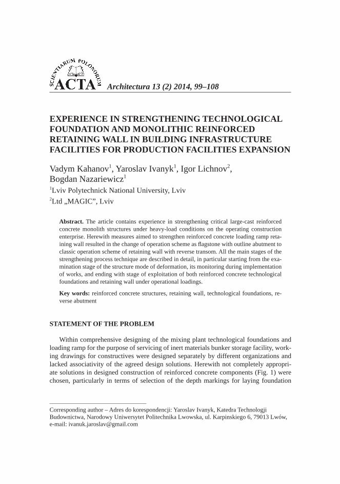
Within comprehensive designing of the mixing plant technological foundations and loading ramp for the purpose of servicing of inert materials bunker storage facility, work-ing drawings for constructives were designed separately by different organizations and lacked associativity of the agreed design solutions. Herewith not completely appropri-ate solutions in designed construction of reinforced concrete components (Fig. 1) were chosen, particularly in terms of selection of the depth markings for laying foundation
100 V. Kahanov, Y. Ivanyk, I. Lichnov, B. Nazariewicz
Acta Sci. Pol.
and designing some sections of retaining wall (Section C). Besides, during construction works, retaining wall subgrade was laid on insuf ciently packed soil which was earlier laid in base through foundation pit reverse lling following the completion of foundation erection of mixing plant technological sink. Calculations for section C of the retaining wall was made as for agstone with outline abutment including reinforced concrete coun-terforts.
Fig. 1. Layout of reinforced concrete loading ramp retaining wall of mixing plant (sections “A”, “B”, “ ”)
Rys. 1. Schemat lokalizacji wzmocnionej elbetowej ciany oporowej rampy za adunkowej w -z a (strefy „A”, „B”, „C”)
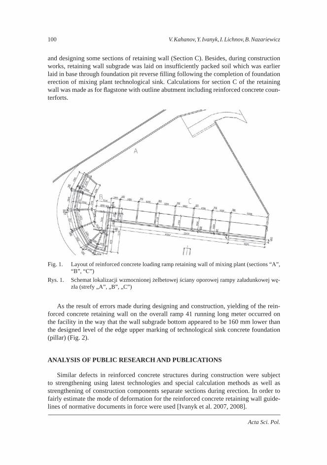
As the result of errors made during designing and construction, yielding of the rein-forced concrete retaining wall on the overall ramp 41 running long meter occurred on the facility in the way that the wall subgrade bottom appeared to be 160 mm lower than the designed level of the edge upper marking of technological sink concrete foundation (pillar) (Fig. 2).
ANALYSIS OF PUBLIC RESEARCH AND PUBLICATIONS
Similar defects in reinforced concrete structures during construction were subject to strengthening using latest technologies and special calculation methods as well as strengthening of construction components separate sections during erection. In order to fairly estimate the mode of deformation for the reinforced concrete retaining wall guide-lines of normative documents in force were used [Ivanyk et al. 2007, 2008].
Experience in strengthening technological foundation... 101
Architectura 13 (2) 2014
Fig. 2. Construction diagram for the technological sink mixing plant and its tangent reinforced concrete loading ramp retaining wall
Rys. 2. Konstrukcja komory technologicznej w z a i styczna do niej elbetowa ciana oporowa rampy za adunkowej
STATEMENT OF THE PURPOSE OF THE ARTICLE
The purpose of this article is to analyze the chosen method of strengthening of re-inforced concrete retaining wall and the implementing technique for certain stages of strengthening construction structures under the conditions of the operating facility.
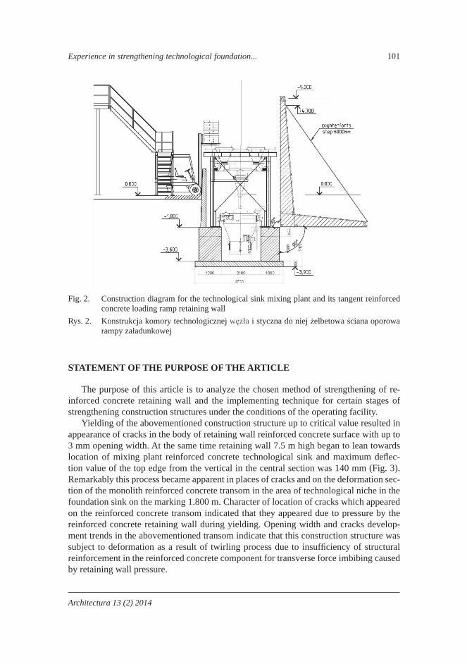
Yielding of the abovementioned construction structure up to critical value resulted in appearance of cracks in the body of retaining wall reinforced concrete surface with up to 3 mm opening width. At the same time retaining wall 7.5 m high began to lean towards location of mixing plant reinforced concrete technological sink and maximum de ec-tion value of the top edge from the vertical in the central section was 140 mm (Fig. 3). Remarkably this process became apparent in places of cracks and on the deformation sec-tion of the monolith reinforced concrete transom in the area of technological niche in the foundation sink on the marking 1.800 m. Character of location of cracks which appeared on the reinforced concrete transom indicated that they appeared due to pressure by the reinforced concrete retaining wall during yielding. Opening width and cracks develop-ment trends in the abovementioned transom indicate that this construction structure was subject to deformation as a result of twirling process due to insuf ciency of structural reinforcement in the reinforced concrete component for transverse force imbibing caused by retaining wall pressure.
102 V. Kahanov, Y. Ivanyk, I. Lichnov, B. Nazariewicz
Acta Sci. Pol.
Fig. 3. Real deformation condition of the retaining wall and location of the loading ramp techno-logical sink during construction of mixing plant
Rys. 3. Faktyczny stan deformacji ciany oporowej i schemat lokalizacji komory technologicznej rampy za adunkowej w trakcie budowy w z a
STATEMENT OF BASIC MATERIAL
In order to stop development of cracks and yielding of reinforced concrete retain-ing wall before the moment of destructive force, examination of defective sections was conducted and comprehensive design for strengthening of bearing components of techno-logical foundations and loading ramp retaining wall was developed.
Specialists of the Scienti c and Research Laboratory of L’viv Polytechnic National University accomplished structure calculations and proposed a comprehensive option of strengthening construction structures in several stages:
removal of niche in the technological sink of mixing plant foundation through strengthened reinforcement and niche building in for the purpose of inclusion into overall operation of the monolith foundation section with transom, which was defor-med due to the pressure from retaining wall during its leaning;
concrete casting of the additional reinforced concrete cambered arch between the two pillars of the trough-shaped technological sink of the mixing plant foundation for the purpose to transfer efforts caused by pressure of soil loaded retaining wall onto rein-forced concrete foundations;
arrangement of superimposed reverse abutment in the reinforced concrete retaining wall through anchoring of 7 reinforcement bars 32A400C in the wall body with 500 mm step in staggered order at the whole length of the loading ramp, which is 41 running meter long.
Experience in strengthening technological foundation... 103
Architectura 13 (2) 2014
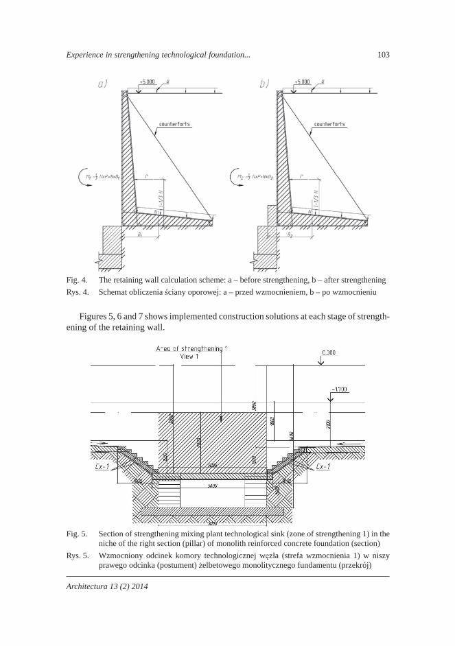
Fig. 4. The retaining wall calculation scheme: a – before strengthening, b – after strengtheningRys. 4. Schemat obliczenia ciany oporowej: a – przed wzmocnieniem, b – po wzmocnieniu
Figures 5, 6 and 7 shows implemented construction solutions at each stage of strength-ening of the retaining wall.
Fig. 5. Section of strengthening mixing plant technological sink (zone of strengthening 1) in the niche of the right section (pillar) of monolith reinforced concrete foundation (section)
Rys. 5. Wzmocniony odcinek komory technologicznej w z a (strefa wzmocnienia 1) w niszy prawego odcinka (postument) elbetowego monolitycznego fundamentu (przekrój)
104 V. Kahanov, Y. Ivanyk, I. Lichnov, B. Nazariewicz
Acta Sci. Pol.
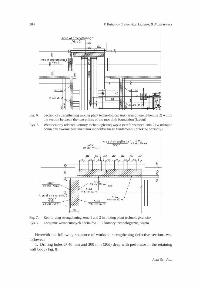
Fig. 6. Section of strengthening mixing plant technological sink (area of strengthening 2) within the section between the two pillars of the monolith foundation (layout)
Rys. 6. Wzmocniony odcinek komory technologicznej w z a (strefa wzmocnienia 2) w odst pie pomi dzy dwoma postumentami monolitycznego fundamentu (przekrój poziomy)
Fig. 7. Reinforcing strengthening zone 1 and 2 in mixing plant technological sinkRys. 7. Zbrojenie wzmocnionych odcinków 1 i 2 komory technologicznej w z a
Herewith the following sequence of works in strengthening defective sections was followed:
1. Drilling holes 40 mm and 300 mm (20d) deep with perforator in the retaining wall body (Fig. 8).
Experience in strengthening technological foundation... 105
Architectura 13 (2) 2014
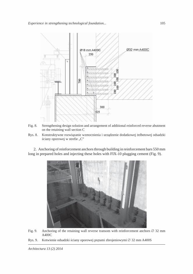
Fig. 8. Strengthening design solution and arrangement of additional reinforced reverse abutment on the retaining wall section C
Rys. 8. Konstruktywne rozwi zanie wzmocnienia i urz dzenie dodatkowej elbetowej odsadzki ciany oporowej w strefie „C”
2. Anchoring of reinforcement anchors through building in reinforcement bars 550 mm long in prepared holes and injecting these holes with FIX-10 plugging cement (Fig. 9).
Fig. 9. Anchoring of the retaining wall reverse transom with reinforcement anchors 32 mm A400C
Rys. 9. Kotwienie odsadzki ciany oporowej pr tami zbrojeniowymi 32 mm A400S

106 V. Kahanov, Y. Ivanyk, I. Lichnov, B. Nazariewicz
Acta Sci. Pol.
3. Reinforcing retaining wall reverse transom of the constructive reinforcement with reinforcement anchors 6 18A400C at the whole length of strengthening area (Fig. 10) along section C.
Fig. 10. Building in anchors 32 mm into loading ramp retaining wall body with FIX-10M plug-ging cement
Rys. 10. Utrwalanie pr tów zbrojeniowych 32 mm elbetowej ciany oporowej rampy za adun-kowej szybkowi cym cementem monta owym FIX-10M
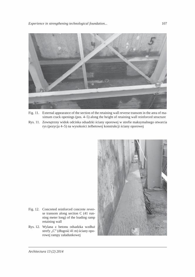
4. Building in reverse reinforced concrete transom (tooth shaped) with ne concrete mixture class B35 using vibration through manual oscillators at the whole length of strengthening area (Fig. 11).
5. As a result of comprehensive measures aimed at retaining wall strengthening, strong reverse transom was made along the whole length of the loading ramp, which rest-ing upon the mixing plant technological sink provided stability of the whole reinforced concrete trestle construction mass. In order to provide perception of temperature effects during loading ramp operation, two movement joints with 13 m step were made in the monolith reinforced concrete structure reverse transom along the whole length of the loading pier of the inert materials bunker storage facility. At the same time, retaining wall calculation operation scheme was altered in principle, in particular operation scheme as agstone with outline abutment was substituted with classic operation scheme of retain-
ing wall with reverse transom (Fig. 12).
Experience in strengthening technological foundation... 107
Architectura 13 (2) 2014
Fig. 11. External appearance of the section of the retaining wall reverse transom in the area of ma-ximum crack openings (pos. 4–5) along the height of retaining wall reinforced structure
Rys. 11. Zewn trzny widok odcinka odsadzki ciany oporowej w strefie maksymalnego otwarcia rys (pozycja 4–5) na wysoko ci elbetowej konstrukcji ciany oporowej
Fig. 12. Concreted reinforced concrete rever-se transom along section C (41 run-ning meter long) of the loading ramp retaining wall
Rys. 12. Wylana z betonu odsadzka wzd u strefy „C” (d ugo 41 m) ciany opo-rowej rampy za adunkowej
108 V. Kahanov, Y. Ivanyk, I. Lichnov, B. Nazariewicz
Acta Sci. Pol.
CONCLUSIONS
Performed measures in terms of strengthening reinforced concrete retaining wall and mixing plant technological foundation sink provided signi cant effect, in particular:
wall yielding stopped, increase of actual rigidity of reinforced concrete sink pillar due to building in of the
technological sink resulted in stopping further crack opening, reinforced concrete wall careen xed and stopped at markings, which were identi ed
at the beginning of strengthening, the project of strengthening of high-durability large-cast reinforced concrete struc-
tures, which were beforehand designated to endure signi cant dynamic loads and dif cult operation mode during exploitation provided conditions for normal operation of the technological facility without considerable expenses for elimination of errors in facility design and construction.
REFERENCES
Ivanyk I.G., Luchko Y.Y., Nazarevych B.L., Parneta B.Z., 2008. Strengthening of monolithic re-inforced concrete structures of buildings and facilities with long operation period with composite materials, Motor Road Service of Ukraine, M.P.Shulgin State Road Scienti c and Research Institute. Collected Articles. Roads and Bridges 9, 149–157.
Ivanyk I.G., Kaganov V.O., Nazarevych B.L., 2007. Experience in reliability enhancement of ex-ploitation of hydraulic facilities on the basis of water pool repair as an example, National University of Water Management and Nature Resources Use, Methods of enhancement of reliability of designing, construction and exploitation of hydraulic melioration facilities, Kyiv, 181–192.
DO WIADCZENIE WZMOCNIENIA FUNDAMENTÓW TECHNOLOGICZNYCH I MONOLITYCZNEJ ELBETOWEJ CIANY OPOROWEJ PODCZAS BUDOWY OBIEKTÓW INFRASTRUKTURY W CZASIE ROZBUDOWY MOCY PRODUKCYJNEJ
Streszczenie. W artykule opisano do wiadczenie wzmocnienia odpowiedzialnych wieloga-barytowych elbetowych monolitycznych konstrukcij, które pracuj w ci kich warunkach eksploatacyjnych dzia aj cego przedsi biorstwa bran y budowlanej. W tym wypadku rod-ki wzmacniaj ce elbetowej ciany oporowej rampy za adunkowej spowodowa y zmiany schematu obliczeniowego pracy – ze schematu p yty opartej konturowo na schemat pracy ciany oporowej z odsadzk . Okre lono szczegó owo wszystkie g ówne etapy technolo-
gii wzmocnienia, zaczynaj c od fazy badania stanu deformacyjno-napr eniowego kon-strukcji, poprzez monitorowanie ca ego okresu pracy, a do etapu eksploatacji elbetowych technologicznych fundamentów oraz ciany oporowej pod obci eniem u ytkowym.
S owa kluczowe: konstrukcje betonowe, mury oporowe, fundamenty technologiczne, od-wrotny obcas
Accepted for print – Zaakceptowano do druku: 5.06.2014