Embed Size (px)
Citation preview
National Aeronautics and Space Administration
www.nasa.gov
FABRICATION AND CHARACTERIZATION OF BRAZED JOINTS FOR SiC-METALLIC
SYSTEMS UTILIZING REFRACTORY METALS
ABSTRACT
Metal to ceramic joining plays a key role for the integration of ceramics into many nuclear,
ground and aero based technologies. In order to facilitate these technologies, the active
metal brazing of silicon carbide (CVD β-SiC, 1.1 mm thick, and hot-pressed α-SiC, 3 mm
thick) to the refractory metals molybdenum and tungsten using active braze alloys was
studied. The joint microstructure, composition, and microhardness were evaluated by
optical microscopy (OM), scanning electron microscopy (SEM), energy dispersive
spectroscopy (EDS), and Knoop hardness testing. The braze alloys, Cusil-ABA, Ticusil
and Copper-ABA, all formed sound joints with excellent wetting and chemical bonding with
the SiC substrate. Despite the close thermal expansion match between the metal
substrates and SiC, hairline cracks formed in α-SiC while β-SiC showed no signs of
residual stress cracking. The use of ductile interlayers to reduce the effect from residual
stresses was investigated and joints formed with copper as an interlayer produced crack
free systems utilizing both CVD and hot-pressed SiC.
1
National Aeronautics and Space Administration
www.nasa.gov 2
Fabrication and Characterization of Brazed Joints for
SiC-Metallic Systems Utilizing Refractory Metals
Bryan Coddington1, Rajiv Asthana1, Michael C. Halbig2 and M. Singh3
1 – University of Wisconsin-Stout, Menomonie, WI
2 – NASA Glenn Research Center, Cleveland, Ohio
3 – Ohio Aerospace Institute, Cleveland, Ohio
35th International Conference and Exposition on Advanced Ceramics and Composites,
Daytona Beach, Florida, January 23rd – 28th , 2011.
National Aeronautics and Space Administration
www.nasa.gov
Outline
• Application
– Nuclear, Electronic, Ground and Aero Based Technologies
• Experimental Procedure / Joint Processing
– Tungsten to SiC Brazing
– Molybdenum to SiC Brazing
– Challenges Encountered
• Characterization
– Optical Microscopy
– Knoop Microhardness Testing
– Scanning Electron Microscopy (SEM) coupled with
Energy Dispersion Spectrometry (EDS)
• Summary and Conclusions
3
National Aeronautics and Space Administration
www.nasa.gov
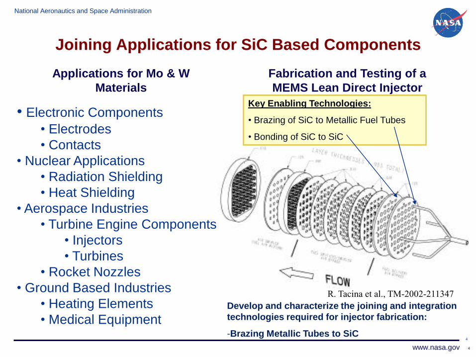
Joining Applications for SiC Based Components
4
Develop and characterize the joining and integration
technologies required for injector fabrication:
-Brazing Metallic Tubes to SiC
Fabrication and Testing of a
MEMS Lean Direct Injector
Key Enabling Technologies:
• Brazing of SiC to Metallic Fuel Tubes
• Bonding of SiC to SiC
R. Tacina et al., TM-2002-211347
4
Applications for Mo & W
Materials
• Electronic Components
• Electrodes
• Contacts
• Nuclear Applications
• Radiation Shielding
• Heat Shielding
• Aerospace Industries
• Turbine Engine Components
• Injectors
• Turbines
• Rocket Nozzles
• Ground Based Industries
• Heating Elements
• Medical Equipment
National Aeronautics and Space Administration
www.nasa.gov
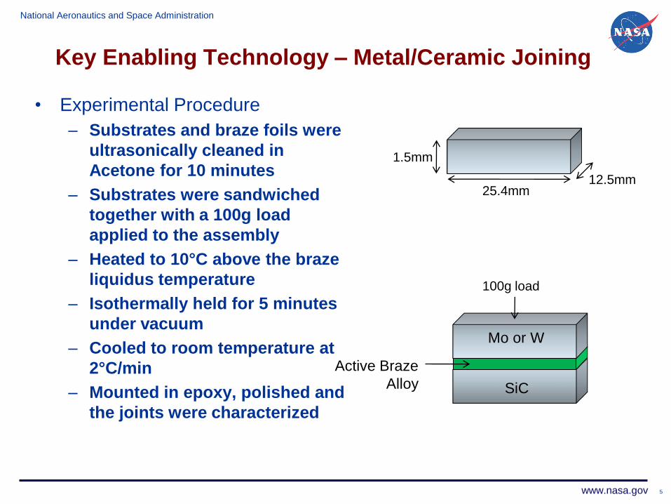
Key Enabling Technology – Metal/Ceramic Joining
• Experimental Procedure
– Substrates and braze foils were
ultrasonically cleaned in
Acetone for 10 minutes
– Substrates were sandwiched
together with a 100g load
applied to the assembly
– Heated to 10°C above the braze
liquidus temperature
– Isothermally held for 5 minutes
under vacuum
– Cooled to room temperature at
2°C/min
– Mounted in epoxy, polished and
the joints were characterized
5
25.4mm12.5mm
100g load
Mo or W
SiC
Active Braze
Alloy
1.5mm
National Aeronautics and Space Administration
www.nasa.gov
Key Enabling Technology – Metal/Ceramic Joining
6
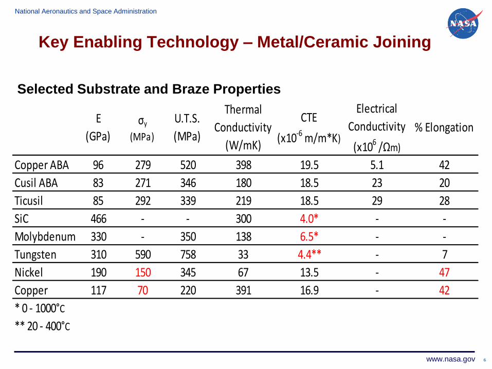
E
(GPa)σy
(MPa)
U.T.S.
(MPa)
Thermal
Conductivity
(W/mK)
CTE
(x10-6 m/m*K)
Electrical
Conductivity
(x106 /Ωm)
% Elongation
Copper ABA 96 279 520 398 19.5 5.1 42
Cusil ABA 83 271 346 180 18.5 23 20
Ticusil 85 292 339 219 18.5 29 28
SiC 466 - - 300 4.0* - -
Molybdenum 330 - 350 138 6.5* - -
Tungsten 310 590 758 33 4.4** - 7
Nickel 190 150 345 67 13.5 - 47
Copper 117 70 220 391 16.9 - 42
* 0 - 1000°C
** 20 - 400°C
Selected Substrate and Braze Properties
National Aeronautics and Space Administration
www.nasa.gov
Key Enabling Technology – Metal/Ceramic Joining
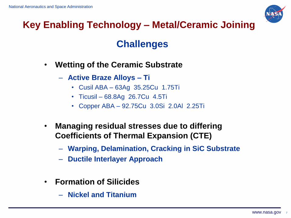
• Wetting of the Ceramic Substrate
– Active Braze Alloys – Ti
• Cusil ABA – 63Ag 35.25Cu 1.75Ti
• Ticusil – 68.8Ag 26.7Cu 4.5Ti
• Copper ABA – 92.75Cu 3.0Si 2.0Al 2.25Ti
• Managing residual stresses due to differing
Coefficients of Thermal Expansion (CTE)
– Warping, Delamination, Cracking in SiC Substrate
– Ductile Interlayer Approach
• Formation of Silicides
– Nickel and Titanium
7
Challenges
National Aeronautics and Space Administration
www.nasa.gov
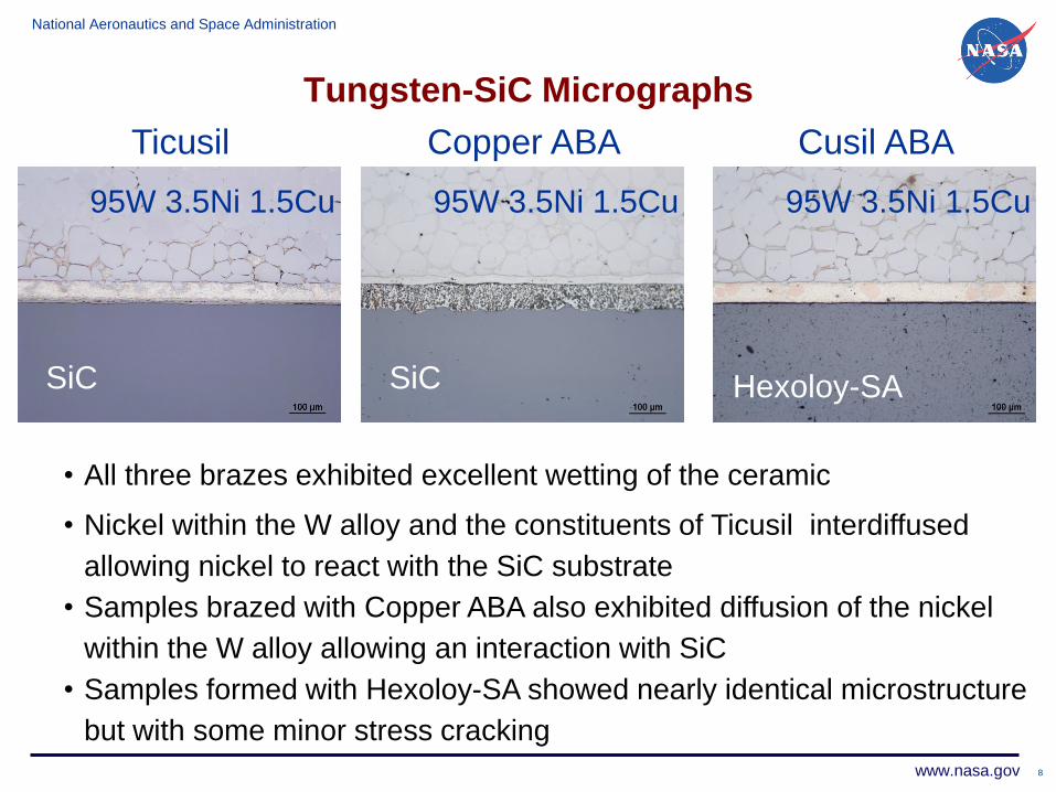
Tungsten-SiC Micrographs
8
Cusil ABATicusil Copper ABA
• All three brazes exhibited excellent wetting of the ceramic
• Nickel within the W alloy and the constituents of Ticusil interdiffused
allowing nickel to react with the SiC substrate
• Samples brazed with Copper ABA also exhibited diffusion of the nickel
within the W alloy allowing an interaction with SiC
• Samples formed with Hexoloy-SA showed nearly identical microstructure
but with some minor stress cracking
SiC
95W 3.5Ni 1.5Cu
SiC
95W 3.5Ni 1.5Cu95W 3.5Ni 1.5Cu
Hexoloy-SA
National Aeronautics and Space Administration
www.nasa.gov
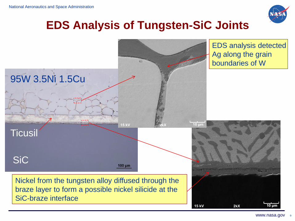
EDS Analysis of Tungsten-SiC Joints
9
Nickel from the tungsten alloy diffused through the
braze layer to form a possible nickel silicide at the
SiC-braze interface
EDS analysis detected
Ag along the grain
boundaries of W
95W 3.5Ni 1.5Cu
Ticusil
SiC

National Aeronautics and Space Administration
www.nasa.gov
Energy Dispersive Spectroscopy (EDS) Analysis of
Braze Reaction Layer at W - Copper ABA Interface
10
Point Marker Si Ti Ni Cu W
1 4.181 0.135 0.797 0.492 93.991
2 2.07 0.574 22.92 2.825 70.832
3 8.599 0.881 14.752 73.708 0.902
4 0.87 8.761 2.966 72.938 2.015
5 18.009 0.695 16.286 58.147 5.424
6 2.075 0.261 8.279 75.169 0
Copper ABA
Tungsten
National Aeronautics and Space Administration
www.nasa.gov
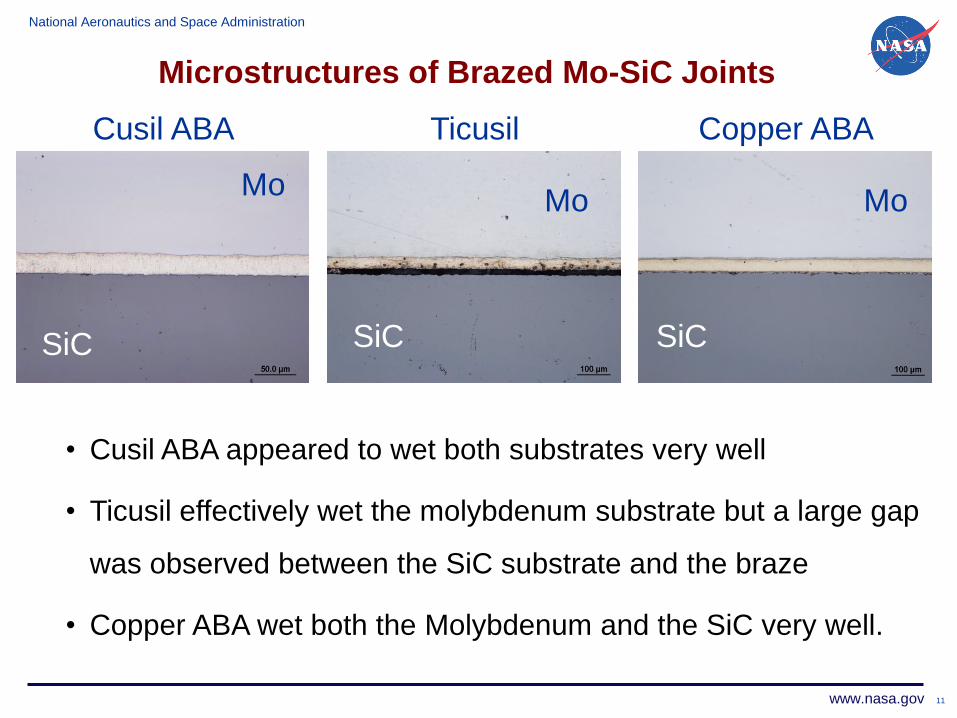
Microstructures of Brazed Mo-SiC Joints
11
Cusil ABA Ticusil Copper ABA
SiC
Ti
• Cusil ABA appeared to wet both substrates very well
• Ticusil effectively wet the molybdenum substrate but a large gap
was observed between the SiC substrate and the braze
• Copper ABA wet both the Molybdenum and the SiC very well.
Mo
SiC
Mo
SiC
Mo
SiC

National Aeronautics and Space Administration
www.nasa.gov
Microstructures of Brazed Mo/Hexoloy-SA
Joints
Samples brazed with Cusil
ABA & Copper ABA
fractured within the Hexoloy-
SA substrate
12
Ticusil
Large crack in
Hexoloy-SA substrate
Hexoloy-SA
Mo
Despite relatively close CTE,
residual stresses caused
extensive cracking within the
Hexoloy-SA substrate
National Aeronautics and Space Administration
www.nasa.gov
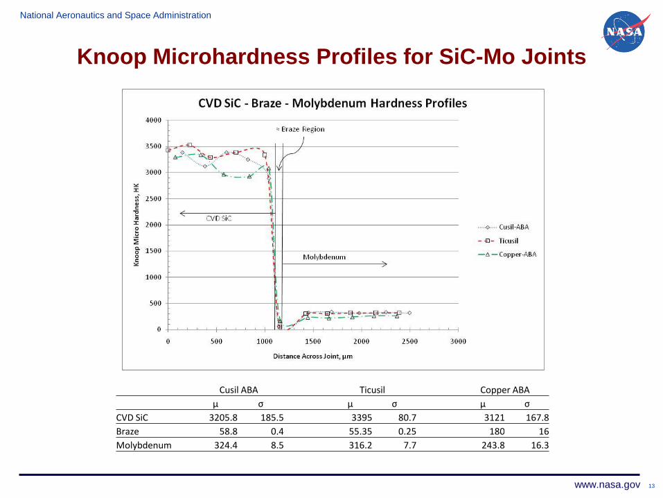
Knoop Microhardness Profiles for SiC-Mo Joints
13
Cusil ABA Ticusil Copper ABA
µ σ µ σ µ σ
CVD SiC 3205.8 185.5 3395 80.7 3121 167.8
Braze 58.8 0.4 55.35 0.25 180 16
Molybdenum 324.4 8.5 316.2 7.7 243.8 16.3
National Aeronautics and Space Administration
www.nasa.gov
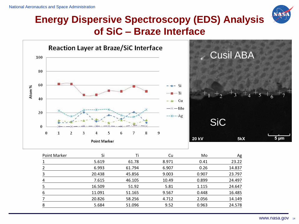
Energy Dispersive Spectroscopy (EDS) Analysis
of SiC – Braze Interface
14
Point Marker Si Ti Cu Mo Ag
1 5.619 61.78 8.971 0.41 23.22
2 6.993 61.794 6.907 0.26 14.837
3 20.438 45.856 9.003 0.907 23.797
4 7.615 46.105 10.49 0.899 24.497
5 16.509 51.92 5.81 1.115 24.647
6 11.091 51.165 9.567 0.448 16.485
7 20.826 58.256 4.712 2.056 14.149
8 5.684 51.096 9.52 0.963 24.578
Cusil ABA
SiC
National Aeronautics and Space Administration
www.nasa.gov
Metallic Interlayer Approach Used to
Absorb Residual Stresses
• SiC – Cusil ABA – Metal system exhibits good
wetting and strong bonding
• Residual stresses are still a major concern
• Ductile interlayer approach is looked at to absorb
thermal induced residual stresses
• Ceramic strain energy calculations are used to
support ductile interlayer approach
15
National Aeronautics and Space Administration
www.nasa.gov
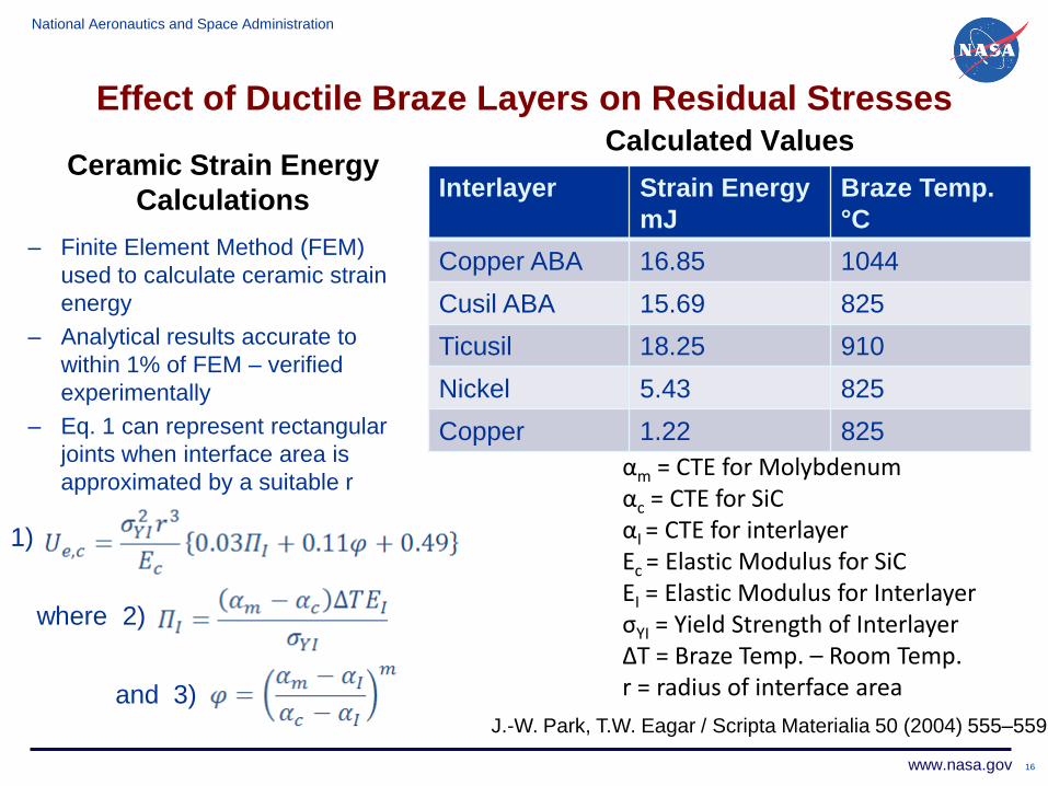
Effect of Ductile Braze Layers on Residual Stresses
Ceramic Strain Energy
Calculations
– Finite Element Method (FEM)
used to calculate ceramic strain
energy
– Analytical results accurate to
within 1% of FEM – verified
experimentally
– Eq. 1 can represent rectangular
joints when interface area is
approximated by a suitable r
Calculated Values
Interlayer Strain Energy
mJ
Braze Temp.
°C
Copper ABA 16.85 1044
Cusil ABA 15.69 825
Ticusil 18.25 910
Nickel 5.43 825
Copper 1.22 825
16
1)
where 2)
and 3)J.-W. Park, T.W. Eagar / Scripta Materialia 50 (2004) 555–559
αm = CTE for Molybdenumαc = CTE for SiCαI = CTE for interlayer Ec = Elastic Modulus for SiCEI = Elastic Modulus for InterlayerσYI = Yield Strength of InterlayerΔT = Braze Temp. – Room Temp. r = radius of interface area
National Aeronautics and Space Administration
www.nasa.gov
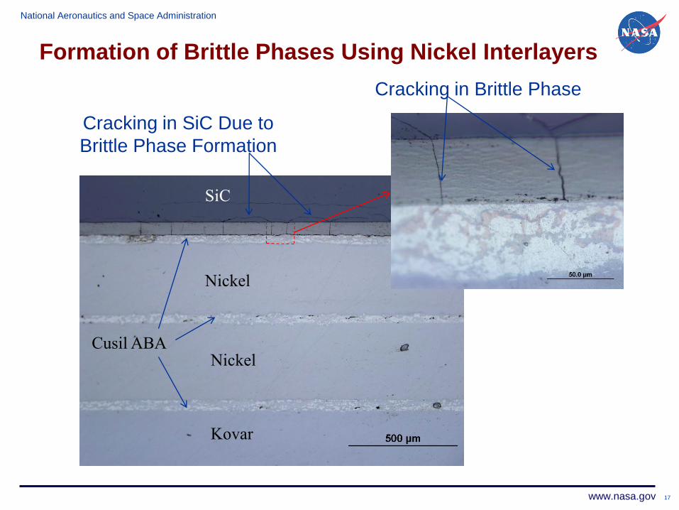
Formation of Brittle Phases Using Nickel Interlayers
17
Nickel
SiC
Nickel
Kovar
Cracking in Brittle Phase
Cracking in SiC Due to
Brittle Phase Formation
Cusil ABA
National Aeronautics and Space Administration
www.nasa.gov 18
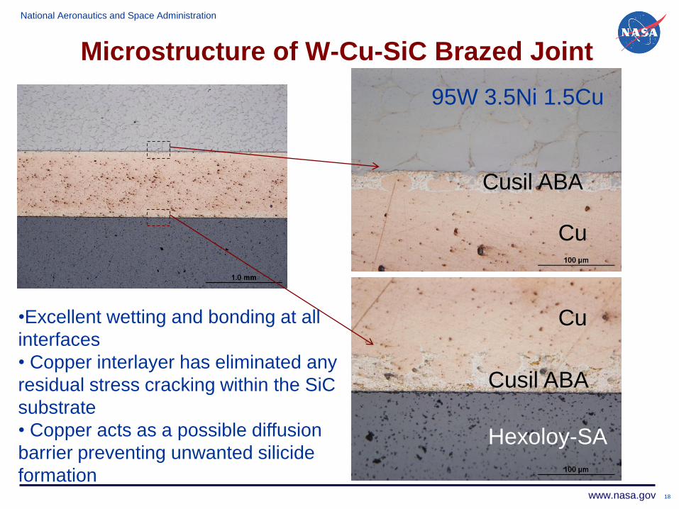
95W 3.5Ni 1.5Cu
Cu
Cu
Hexoloy-SA
Cusil ABA
Cusil ABA
•Excellent wetting and bonding at all
interfaces
• Copper interlayer has eliminated any
residual stress cracking within the SiC
substrate
• Copper acts as a possible diffusion
barrier preventing unwanted silicide
formation
Microstructure of W-Cu-SiC Brazed Joint
National Aeronautics and Space Administration
www.nasa.gov 19
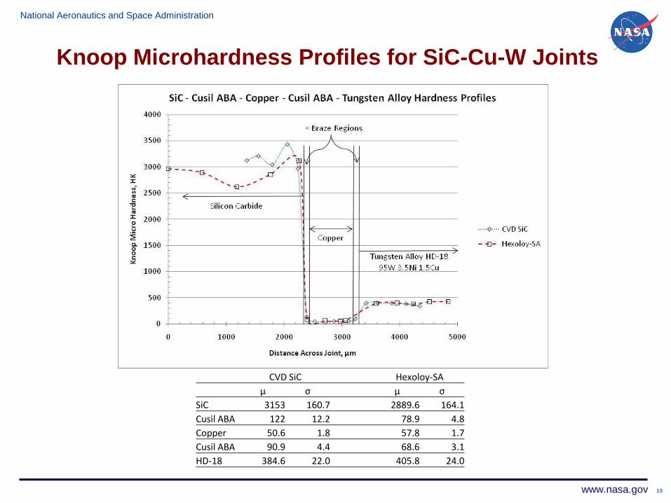
CVD SiC Hexoloy-SA
µ σ µ σ
SiC 3153 160.7 2889.6 164.1
Cusil ABA 122 12.2 78.9 4.8
Copper 50.6 1.8 57.8 1.7
Cusil ABA 90.9 4.4 68.6 3.1
HD-18 384.6 22.0 405.8 24.0
Knoop Microhardness Profiles for SiC-Cu-W Joints
National Aeronautics and Space Administration
www.nasa.gov
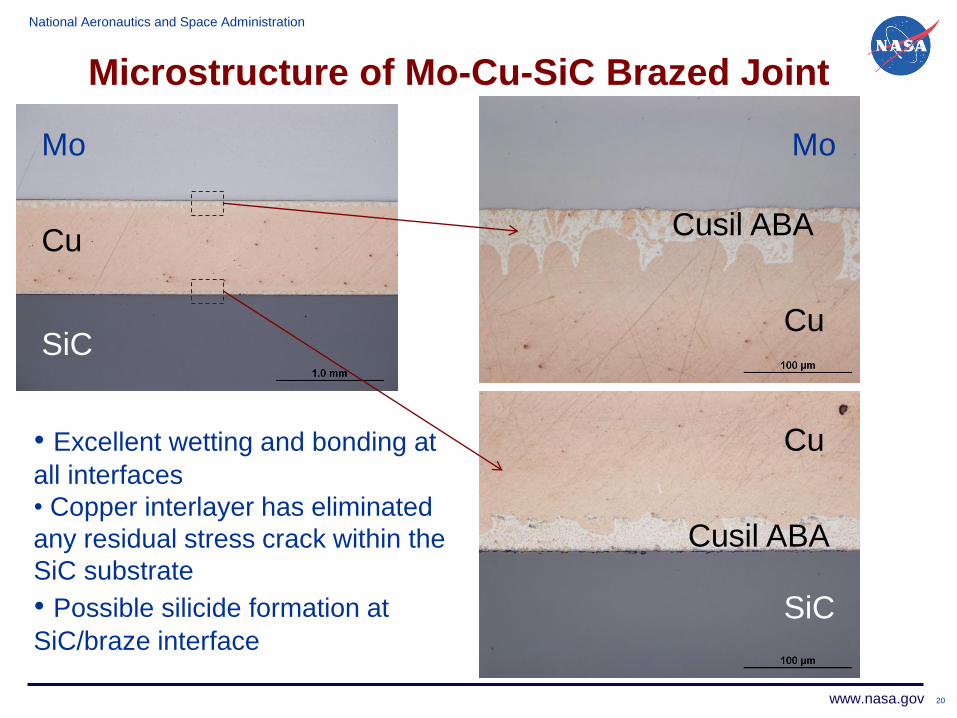
Microstructure of Mo-Cu-SiC Brazed Joint
20
Mo
Cu
SiC
Mo
Cu
Cu
SiC
Cusil ABA
Cusil ABA
• Excellent wetting and bonding at
all interfaces
• Copper interlayer has eliminated
any residual stress crack within the
SiC substrate
• Possible silicide formation at
SiC/braze interface
National Aeronautics and Space Administration
www.nasa.gov 21
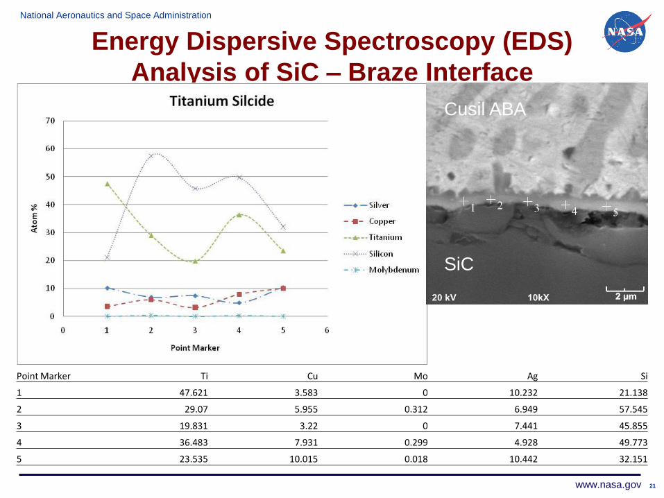
Energy Dispersive Spectroscopy (EDS)
Analysis of SiC – Braze Interface
21
Point Marker Ti Cu Mo Ag Si
1 47.621 3.583 0 10.232 21.138
2 29.07 5.955 0.312 6.949 57.545
3 19.831 3.22 0 7.441 45.855
4 36.483 7.931 0.299 4.928 49.773
5 23.535 10.015 0.018 10.442 32.151
Cusil ABA
SiC
National Aeronautics and Space Administration
www.nasa.gov
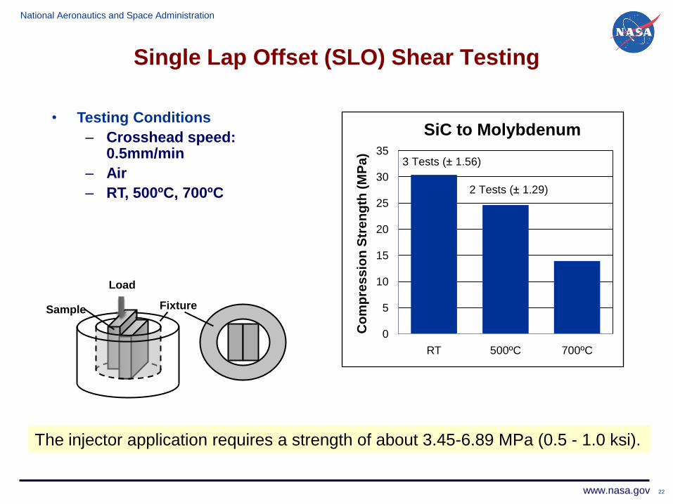
Single Lap Offset (SLO) Shear Testing
22
0
5
10
15
20
25
30
35
RT 500ºC 700ºCC
om
pre
ss
ion
Str
en
gth
(M
Pa
)
SiC to Molybdenum
3 Tests (± 1.56)
2 Tests (± 1.29)
Sample
Load
Fixture
• Testing Conditions
– Crosshead speed: 0.5mm/min
– Air
– RT, 500ºC, 700ºC
The injector application requires a strength of about 3.45-6.89 MPa (0.5 - 1.0 ksi).
National Aeronautics and Space Administration
www.nasa.gov
Summary and Conclusions
23
• Cusil ABA offered excellent wetting of the SiC and Metal
substrates
• Brazing SiC to Molybdenum or Tungsten introduced residual stresses and caused cracking in the α-SiC substrate despite
relatively small CTE mismatch.
• The use of nickel interlayers in a SiC system produced
extensive diffusion of the nickel forming a possible nickel silicide
• Copper interlayers proved to be capable of absorbing residual
stresses introduced from brazing and acted as a diffusion barrier
preventing unwanted silicide and carbide formation
• Initial mechanical testing shows that Mo-SiC joints brazed with a
copper interlayer are capable of high strength – failure typically
occurred within the ceramic
National Aeronautics and Space Administration
www.nasa.gov
Acknowledgements
• One of the authors (Bryan C.) would like to thank LERCIP
Program at NASA Glenn Research Center for summer research
support and the University of Wisconsin-Stout for providing the
necessary funding to present this research
24