Embed Size (px)
Citation preview

DEVELOPMENT OF IN-STREAM CROSS FLOW MICRO HYDRO
TURBINE
Siti Mas Arena binti Liakbar
Master of Engineering
(Mechanical and Manufacturing Engineering)
2013
Faculty of Engineering
UNIVERSITI MALAYSIA SARAWAK
CATATAN: * Tesis dimaksudkan sebagai tesis bagi Ijazah Doktor Falsafah, Sarjana
dan Sarjana Muda.
** Jika tesis ini SULIT atau TERHAD, sila lampirkan surat daripada
pihak berkuasa/organisasi berkenaan dengan menyatakan sekali sebab
dan tempoh tesis ini perlu dikelaskan sebagai SULIT atau TERHAD.
BORANG PENGESAHAN STATUS TESIS
Judul: DEVELOPMENT OF IN-STREAM CROSS FLOW MICRO HYDRO TURBINE
SESI PENGAJIAN: 2011/2012
Saya SITI MAS ARENA BINTI LIAKBAR__
mengaku membenarkan tesis * ini disimpan di Pusat Khidmat Maklumat Akademik, Universiti
Malaysia Sarawak dengan syarat-syarat kegunaan seperti berikut:
1. Tesis adalah hakmilik Universiti Malaysia Sarawak.
2. Pusat Khidmat Maklumat Akademik, Universiti Malaysia Sarawak dibenarkan membuat
salinan untuk tujuan pengajian sahaja.
3. Membuat pendigitan untuk membangunkan pangkalan Data Kandungan Tempatan.
4. Pusat Khidmat Maklumat Akademik, Universiti Malaysia Sarawak dibenarkan membuat
salinan tesis ini sebagai bahan pertukaran antara institusi pengajian tinggi.
5. **Sila tandakan ( √ )di kotak yang berkenaan:
SULIT (Mengandungi maklumat yang berdarjah keselamatan atau
kepentingan Malaysia seperti yang termaktub di dalam AKTA
RAHSIA RASMI 1972)
TERHAD (Mengandungi maklumat TERHAD yang telah ditentukan oleh
organisasi/ badan dimana penyelidikan dijalankan)
TIDAK TERHAD
Disahkan oleh
(TANDATANGAN PENULIS) (TANDATANGAN PENYELIA)
Alamat Tetap: No 17, Lot 3744, Blok 26 Assoc. Prof Dr. M. Shahidul Islam
Taman Univista
94300 Kota Samarahan
Sarawak.
Tarikh: Tarikh:
√

APPROVAL SHEET
This Master Thesis, which entitled “Development of In-Stream Cross Flow
Micro Hydro Turbine”, was prepared by Siti Mas Arena binti Liakbar as
a partial fulfillment for Master of Engineering (Mechanical and
Manufacturing Engineering) is hereby read and approved by:
Assoc. Prof. Dr. M. Shahidul Islam Signature: _____________________
Project Supervisor Date : _____________________
Faculty of Engineering
Universiti Malaysia Sarawak
DEVELOPMENT OF IN-STREAM CROSS FLOW MICRO HYDRO
TURBINE
SITI MAS ARENA BINTI LIAKBAR
This project is submitted in partial fulfilment of the requirement for the Master
of Engineering (Mechanical and Manufacturing Engineering)
Faculty of Engineering
UNIVERSITI MALAYSIA SARAWAK
2013

Specially dedicate to my loving family, who has supported and encouraged me
through good time and hard time
ii
ACKNOWLEDGEMENT
In the name of Allah, the Most Gracious and the Most Merciful
Alhamdulillah, all praises to Allah for the strengths and His blessing in completing
this thesis. Special appreciation goes to my supervisor, Assoc Prof Dr M Shahidul
Islam, for his supervision and constant support. He inspired me greatly to work in
this project. Not forgotten, my appreciation to my co-supervisor, Dr. Syed Tarmizi
Syed Shazali and Dr Thelaha Masri for their support and knowledge regarding to this
project.
I would like to express my appreciation to financial support given by Research &
Innovation Section, JKR Malaysia Training & Research Division and Faculty of
Engineering, UNIMAS.
Many thanks go to my lecturer Abg Mohd Nizam Abg Kamaruddin and all
technician staff of the Mechanical Engineering Department and Chemical
Engineering Department for their advice, opinion and help throughout this project.
Sincere thanks to all my friends especially Hafiza and Akmal for their kindness and
moral support during my study.
Last but not least, my deepest gratitude goes to my beloved parents; Mr. Liakbar
Matusin and Mrs. Jeriah Ali Hassan and also to my sisters for their endless love,
prayers and encouragement. To those who indirectly contributed in this research,
your kindness means a lot to me.
iii
ABSTRACT
The advancement of present world is largely depending on fossil fuel which is a
proven cause of global warming. This research has been undertaken to develop an
in-stream low velocity water turbine by extracting green energy in order to reduce
burning of fossil fuel and to uphold the concept of sustainable environment. This
research aims to develop a laboratory scale (LST) and prototype cross flow micro
hydro turbine (CFMHT) by extracting kinetic energy from in-stream water. Ducting
system and flywheel concept have been incorporated into structure of CFMHT for
increasing energy extraction and to maintain uniform speed in turbine operations.
The results reported in this thesis have shown that at duct angle 45o both in inlet-
outlet, LST has extracted 2.3 Watt at water velocity 0.5 m/s which contributed to
generate turbine speed 70 RPM. On the other hand, prototype turbine test at duct
angle 45o both in inlet-outlet have shown that at water velocity 0.3 m/s, energy
extraction was 5.42 Watt which contributed to turbine speed 18 RPM. Development
of micro hydro turbine has huge used in off grid areas for providing clean energy.
This energy will contribute to grow small scale agriculture projects and SME which
will create employment opportunities. This study suggests for further study by
improving its energy extraction efficiency and developing a feasible installation
system in in-stream water for continuous operations.
iv
ABSTRAK
Kemajuan dunia sekarang sangat bergantung kepada bahan api fosil yang merupakan
punca pemanasan global. Kajian ini telah dijalankan untuk membangunkan turbin
dalam aliran air perlahan dengan mengekstrak tenaga hijau dalam usaha untuk
mengurangkan pembakaran bahan api fosil dan untuk menegakkan konsep
persekitaran mampan. Kajian ini bertujuan untuk membangunkan skala makmal
(LST) dan prototaip aliran silang mikro hidro turbin (CFMHT) dengan mengekstrak
tenaga kinetik daripada air dalam aliran. Menyalurkan konsep sistem dan roda tenaga
telah dimasukkan ke dalam struktur CFMHT untuk pengekstrakan tenaga yang
semakin meningkat dan untuk mengekalkan kelajuan seragam dalam operasi turbin.
Keputusan yang dilaporkan dalam tesis ini telah menunjukkan bahawa pada sudut
45o di kedua-dua masuk keluar saluran, LST telah diekstrak 2.3 Watt pada halaju air
0.5 m/s yang menyumbang untuk menjana kelajuan turbin 70 RPM. Selain itu, ujian
prototaip turbin pada 45o di kedua-dua masuk keluar saluran telah menunjukkan
bahawa pada halaju air 0.3 m/s, pengekstrakan tenaga adalah 5.42 Watt yang
menyumbang kepada turbin RPM kelajuan 18. Pembangunan mikro hidro turbin
banyak digunakan di kawasan grid off untuk menyediakan tenaga bersih. Tenaga ini
akan menyumbang untuk mengembangkan projek pertanian berskala kecil dan PKS
yang akan mewujudkan peluang pekerjaan. Kajian ini mencadangkan untuk kajian
selanjutnya dengan meningkatkan kecekapan pengeluaran tenaga dan membangun
satu sistem pemasangan dilaksanakan dalam air untuk operasi berterusan.
v
TABLE OF CONTENTS
Page
ACKNOWLEDGEMENT ii
ABSTRACT iii
ABSTRAK iv
TABLE OF CONTENT v
LIST OF TABLES viii
LIST OF FIGURES ix
NOMENCLATURE xii
CHAPTER 1 INTRODUCTION
1.0 Background of Study 1
1.1 Research Problem Statements 3
1.2 Objectives of Research 4
1.3 Research Novelty 5
1.4 Thesis Outline 5
CHAPTER 2 LITERATURE REVIEW
2.0 Introduction 7
2.1 Energy Supply and Power Generation 8
2.2 Green Energy 11
2.3 Components of Micro Hydro Schemes 14
2.4 Micro Hydro Turbine 17
2.5 Overview on Micro Hydro Project 23
2.6 Research and Development on Micro Hydro in
Malaysia
29
2.7 Development of Energy Transmission for Micro
Hydro Turbine
34
2.8 Mathematical Models of Micro Hydro 43
2.9 Findings of Literature Review 45
2.10 Scope of Study under this Research Project 46
vi
2.11 Conclusion 47
CHAPTER 3 RESEARCH METHODOLOGY
3.0 Introduction 48
3.1 Research Framework 49
3.2 Simulation of Energy Extraction and Shaft
Power
50
3.3 Simulation of Energy Flow 50
3.4 Procedure of Developing Laboratory Scale and
Prototype CFMHT
50
3.5 Conclusion 57
CHAPTER 4 DEVELOPMENT OF CFMHT
4.0 Introduction 58
4.1 Designing Laboratory Scale CFMHT 60
4.2 Fabrication of Laboratory Scale CFMHT 61
4.3 Experiment Setup of Laboratory Scale CFMHT 62
4.4 Test Run of Laboratory Scale CFMHT 64
4.5 Designing Prototype CFMHT 65
4.6 Fabrication of Prototype CFMHT 67
4.7 Experiment Setup for Prototype CFMHT 72
4.8 Test Run of Prototype CFMHT 74
4.9 Conclusion 75
CHAPTER 5 RESULTS AND DISCUSSION
5.0 Introduction 76
5.1 Simulation and Findings 76
5.1.1 Simulation of Energy Extraction and
Shaft Power
76
5.1.2 Simulation of Energy Flow 80
5.2 Test Result and Analysis of Operating Behaviour
of LST
83
5.3 Data Analysis and Evaluation of Operating 93
vii
Behaviour of Prototype Turbine
5.4 Comparative Statement on Findings of
Laboratory Scale and Prototype CFMHT
99
5.5 Evaluation on LST and Prototype Turbine
Performance
101
5.6 Research Findings 102
5.7 Conclusion 104
CHAPTER 6 CONCLUSION AND RECOMENDATIONS
6.0 Summary of Research 105
6.1 Constraints in Research 107
6.2 Contribution of Research 108
6.3 Social Implications of Research 108
6.4 Environmental Implications of Research 109
6.5 Conclusion 109
6.6 Recommendations 110
REFERENCES 114
APPENDIX I 120
APPENDIX II 125
APPENDIX III 137
APPENDIX IV 145
viii
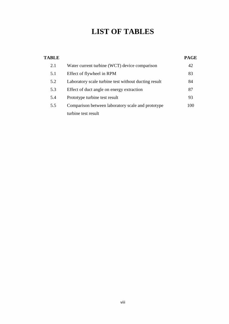
LIST OF TABLES
TABLE PAGE
2.1 Water current turbine (WCT) device comparison 42
5.1 Effect of flywheel in RPM 83
5.2 Laboratory scale turbine test without ducting result 84
5.3 Effect of duct angle on energy extraction 87
5.4 Prototype turbine test result 93
5.5 Comparison between laboratory scale and prototype
turbine test result
100

ix
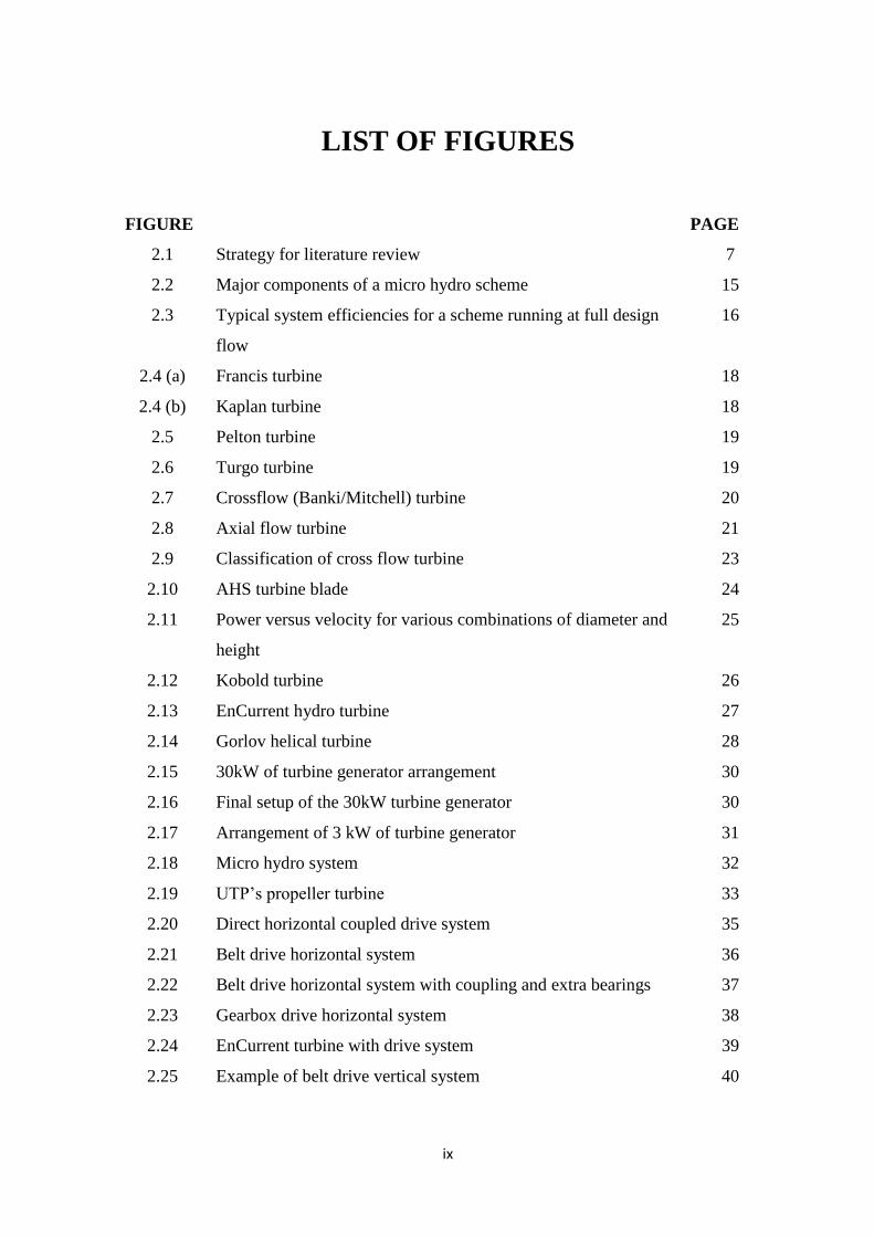
LIST OF FIGURES
FIGURE PAGE
2.1 Strategy for literature review 7
2.2 Major components of a micro hydro scheme 15
2.3 Typical system efficiencies for a scheme running at full design
flow
16
2.4 (a) Francis turbine 18
2.4 (b) Kaplan turbine 18
2.5 Pelton turbine 19
2.6 Turgo turbine 19
2.7 Crossflow (Banki/Mitchell) turbine 20
2.8 Axial flow turbine 21
2.9 Classification of cross flow turbine 23
2.10 AHS turbine blade 24
2.11 Power versus velocity for various combinations of diameter and
height
25
2.12 Kobold turbine 26
2.13 EnCurrent hydro turbine 27
2.14 Gorlov helical turbine 28
2.15 30kW of turbine generator arrangement 30
2.16 Final setup of the 30kW turbine generator 30
2.17 Arrangement of 3 kW of turbine generator 31
2.18 Micro hydro system 32
2.19 UTP’s propeller turbine 33
2.20 Direct horizontal coupled drive system 35
2.21 Belt drive horizontal system 36
2.22 Belt drive horizontal system with coupling and extra bearings 37
2.23 Gearbox drive horizontal system 38
2.24 EnCurrent turbine with drive system 39
2.25 Example of belt drive vertical system 40
x
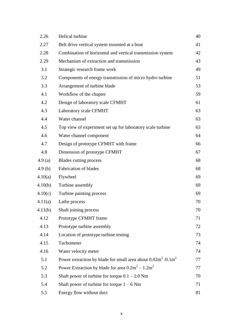
2.26 Helical turbine 40
2.27 Belt drive vertical system mounted at a boat 41
2.28 Combination of horizontal and vertical transmission system 42
2.29 Mechanism of extraction and transmission 43
3.1 Strategic research frame work 49
3.2 Components of energy transmission of micro hydro turbine 51
3.3 Arrangement of turbine blade 53
4.1 Workflow of the chapter 59
4.2 Design of laboratory scale CFMHT 61
4.3 Laboratory scale CFMHT 63
4.4 Water channel 63
4.5 Top view of experiment set up for laboratory scale turbine 63
4.6 Water channel component 64
4.7 Design of prototype CFMHT with frame 66
4.8 Dimension of prototype CFMHT 67
4.9 (a) Blades cutting process 68
4.9 (b) Fabrication of blades 68
4.10(a) Flywheel 69
4.10(b) Turbine assembly 69
4.10(c) Turbine painting process 69
4.11(a) Lathe process 70
4.11(b) Shaft joining process 70
4.12 Prototype CFMHT frame 71
4.13 Prototype turbine assembly 72
4.14 Location of prototype turbine testing 73
4.15 Tachometer 74
4.16 Water velocity meter 74
5.1 Power extraction by blade for small area about 0.02m2
-0.1m2 77
5.2 Power Extraction by blade for area 0.2m2 – 1.2m
2 77
5.3 Shaft power of turbine for torque 0.1 – 2.0 Nm 70
5.4 Shaft power of turbine for torque 1 – 6 Nm 71
5.5 Energy flow without duct 81
xi
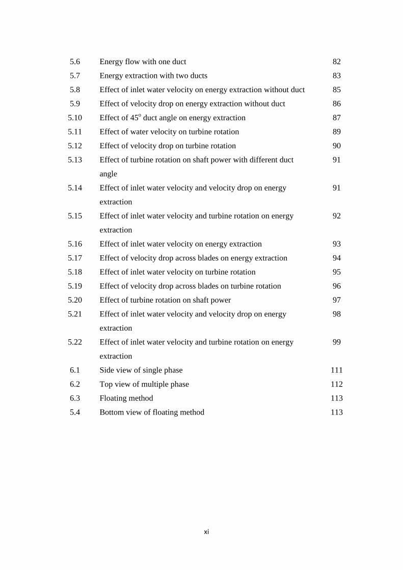
5.6 Energy flow with one duct 82
5.7 Energy extraction with two ducts 83
5.8 Effect of inlet water velocity on energy extraction without duct 85
5.9 Effect of velocity drop on energy extraction without duct 86
5.10 Effect of 45o duct angle on energy extraction 87
5.11 Effect of water velocity on turbine rotation 89
5.12 Effect of velocity drop on turbine rotation 90
5.13 Effect of turbine rotation on shaft power with different duct
angle
91
5.14 Effect of inlet water velocity and velocity drop on energy
extraction
91
5.15 Effect of inlet water velocity and turbine rotation on energy
extraction
92
5.16 Effect of inlet water velocity on energy extraction 93
5.17 Effect of velocity drop across blades on energy extraction 94
5.18 Effect of inlet water velocity on turbine rotation 95
5.19 Effect of velocity drop across blades on turbine rotation 96
5.20 Effect of turbine rotation on shaft power 97
5.21 Effect of inlet water velocity and velocity drop on energy
extraction
98
5.22 Effect of inlet water velocity and turbine rotation on energy
extraction
99
6.1 Side view of single phase 111
6.2 Top view of multiple phase 112
6.3 Floating method 113
5.4 Bottom view of floating method 113
ix
LIST OF FIGURES
FIGURE PAGE
2.1 Strategy for literature review 7
2.2 Major components of a micro hydro scheme 15
2.3 Typical system efficiencies for a scheme running at full design
flow
16
2.4 (a) Francis turbine 18
2.4 (b) Kaplan turbine 18
2.5 Pelton turbine 19
2.6 Turgo turbine 19
2.7 Crossflow (Banki/Mitchell) turbine 20
2.8 Axial flow turbine 21
2.9 Classification of cross flow turbine 23
2.10 AHS turbine blade 24
2.11 Power versus velocity for various combinations of diameter and
height
25
2.12 Kobold turbine 26
2.13 EnCurrent hydro turbine 27
2.14 Gorlov helical turbine 28
2.15 30kW of turbine generator arrangement 30
2.16 Final setup of the 30kW turbine generator 30
2.17 Arrangement of 3 kW of turbine generator 31
2.18 Micro hydro system 32
2.19 UTP’s propeller turbine 33
2.20 Direct horizontal coupled drive system 35
2.21 Belt drive horizontal system 36
2.22 Belt drive horizontal system with coupling and extra bearings 37
2.23 Gearbox drive horizontal system 38
2.24 EnCurrent turbine with drive system 39
2.25 Example of belt drive vertical system 40

x
2.26 Helical turbine 40
2.27 Belt drive vertical system mounted at a boat 41
2.28 Combination of horizontal and vertical transmission system 42
2.29 Mechanism of extraction and transmission 43
3.1 Strategic research frame work 49
3.2 Components of energy transmission of micro hydro turbine 51
3.3 Arrangement of turbine blade 53
4.1 Workflow of the chapter 59
4.2 Design of laboratory scale CFMHT 61
4.3 Laboratory scale CFMHT 63
4.4 Water channel 63
4.5 Top view of experiment set up for laboratory scale turbine 63
4.6 Water channel component 64
4.7 Design of prototype CFMHT with frame 66
4.8 Dimension of prototype CFMHT 67
4.9 (a) Blades cutting process 68
4.9 (b) Fabrication of blades 68
4.10(a) Flywheel 69
4.10(b) Turbine assembly 69
4.10(c) Turbine painting process 69
4.11(a) Lathe process 70
4.11(b) Shaft joining process 70
4.12 Prototype CFMHT frame 71
4.13 Prototype turbine assembly 72
4.14 Location of prototype turbine testing 73
4.15 Tachometer 74
4.16 Water velocity meter 74
5.1 Power extraction by blade for small area about 0.02m2
-0.1m2 77
5.2 Power Extraction by blade for area 0.2m2 – 1.2m
2 77
5.3 Shaft power of turbine for torque 0.1 – 2.0 Nm 70
5.4 Shaft power of turbine for torque 1 – 6 Nm 71
5.5 Energy flow without duct 81

xi
5.6 Energy flow with one duct 82
5.7 Energy extraction with two ducts 83
5.8 Effect of inlet water velocity on energy extraction without duct 85
5.9 Effect of velocity drop on energy extraction without duct 86
5.10 Effect of 45o duct angle on energy extraction 87
5.11 Effect of water velocity on turbine rotation 89
5.12 Effect of velocity drop on turbine rotation 90
5.13 Effect of turbine rotation on shaft power with different duct
angle
91
5.14 Effect of inlet water velocity and velocity drop on energy
extraction
91
5.15 Effect of inlet water velocity and turbine rotation on energy
extraction
92
5.16 Effect of inlet water velocity on energy extraction 93
5.17 Effect of velocity drop across blades on energy extraction 94
5.18 Effect of inlet water velocity on turbine rotation 95
5.19 Effect of velocity drop across blades on turbine rotation 96
5.20 Effect of turbine rotation on shaft power 97
5.21 Effect of inlet water velocity and velocity drop on energy
extraction
98
5.22 Effect of inlet water velocity and turbine rotation on energy
extraction
99
6.1 Side view of single phase 111
6.2 Top view of multiple phase 112
6.3 Floating method 113
5.4 Bottom view of floating method 113
xii
NOMENCLATURE
V - Water velocity (m/s)
Vi - Inlet water velocity (m/s)
Vo - Outlet water velocity (m/s)
ΔV - Velocity drop (%)
Pb - Energy extraction (W)
T - Torque (Nm)
Ps - Shaft power (W)
LST - Laboratory scale turbine
CFMHT - Cross flow micro hydro turbine
RPM -Revolution per minute
Subscripts
i - inlet
o - outlet
b - blade
s - shaft
1
CHAPTER 1
INTRODUCTION
1.0 Background of Study
Malaysia is well endowed with both conventional and renewable sources of
energy; and these energy sources have been contributing significantly to rapid
growth of Malaysian economy. Among the conventional energy sources fossil fuel
is the component which composed of gas, oil and coal; on the other hand, in
Malaysia, the main part of renewable energy is hydroelectricity; however, the share
of fossil fuel in Malaysian fuel mix is about 93% (Penny et al., 2010).
It has been recorded that the burning of fossil fuel is the main cause of global
warming (Ong et al., 2011) and by products of this fuel such as CO2, SO2 and NOx
are the threatening factors to environment. Indeed, these gases are also known to be
greenhouse gas. Eventually, these gases are contributing to increase pollution density
in air and makes ecosystem unbalance (Cowan & Harmon, 2007). The current
estimated emission, due to burning of fossil fuel in Malaysia in the year 2010, is
about 56,643,906 ton; and the significant part is coming from manufacturing
industries. Nowadays, Malaysia is moving toward industrial economy; obviously,
which will create more electricity demand. This information indicates that Malaysian
economy is going to be highly depending on energy. If this country continue to grow
with fossil fuel energy; the present ecosystem will be unbalanced; which may lead
towards unsustainable economic development. In order to maintain a sustainable

2
industrial growth and economy, pollution free energy production is essential. To
address this sensitive issue, R&D on energy sector is essential. Indeed, the current
research project has been undertaken to meet this challenge; with a target for
developing a technically and economically feasible water turbine suitable for
Malaysian environment. It is obvious to state that this research project was served a
small part of the requirement for developing micro hydro turbine for producing
electricity from green energy sources.
Recently, micro-hydro projects are becoming popular to society for generating
electricity due to no fuel cost for them. Micro hydro converts the kinetic and
potential energy of flowing water through water turbine shaft to generator for
producing electricity. Most large scale hydro usually install with dam to ensure
maximum power output. In contrast, most in-stream micro hydro water flow is used
in turbine blade, after which it is returned to main stream. The efficiency of most
micro hydro generators founds in a range of 30 to 70%. The micro hydro system is
suitable for “run-of-the-river” installations because it is not connected to the grid and
also suitable for remote rural areas. As dam is not required to operate in-stream
micro hydro systems, the capital cost of this type of turbine is less compare to the
large scale hydro systems (Hislop, 1992). Latest studies on micro hydro system
suggest that this source is reliable and friendly to environment compare to other
sources of energy. It also provides solution with energy supply for remote and hilly
areas where the extension of grid system is not economically and technically feasible
(Nathan et al., 2009). But the main constrain in operations of this type of turbine are;
insufficient water flow and in case of water velocity less than 1 m/s (V < 1 m/s). In
these two cases this turbine is fully inefficient.
3
1.1 Research Problem Statements
Malaysian electricity generation is heavily dependent on fossil fuels and the
share of renewable energy in the electricity generation is insignificant. Although it is
a commonly known fact that the fossil fuel sources in Malaysia are finite and
gradually depleting and at the same time burning of fossil fuels is the main sources of
emission of greenhouse gases. For that reason, research project of green energy
should be taken to develop a green and economically electricity generation system
suitable for Malaysian economy.
Indeed, energy extraction by turbine blades is the main issue of this research
project but the optimization of energy extraction is key factor of success of this
research project. The flow direction of water stream at inlet and outlet points of
turbine could play a vital role in releasing its inherent kinetic energy to turbine
blades. Hence controlling water flow direction need consider for optimizing energy
extraction.
On the other hand, most of commercial available micro hydro turbine are
suitable operate at water velocity more than or equal 1m/s. However, major
percentages of people are living in rural area where water velocity is about 1m/s or
less. This is a constraint of using commercial available micro hydro turbine. Hence,
developing a micro hydro turbine which is suitable to operate at low water velocity is
key analytical factor needs to address carefully in order to design efficient micro
hydro turbine.
4
1.2 Objectives of Research
The main objective of this study is to develop an in-stream low velocity
CFMHT and test for characterizing operating performance. In order to achieve
research objective, this research is focused on the following specific objectives:
1. To simulate:
i. Energy flow through turbine
ii. Energy extraction and shaft power
2. To develop laboratory scale CFMHT for studying operating behaviour of
turbine
3. To develop prototype CFMHT for studying operating behaviour of turbine
The operating behaviour of turbine is focused on:
i. Effect of flywheel on Turbine RPM
ii. Effect of inlet water velocity on energy extraction
iii. Effect of velocity drop on energy extraction
iv. Effect of duct angle on energy extraction
v. Effect of water velocity on turbine rotation
vi. Effect of velocity drop on turbine rotation
vii. Effect of turbine RPM on shaft power
viii. Combine effect of inlet velocity and velocity drop on energy
extraction
ix. Combine effect of inlet water velocity and turbine rotation on energy
extraction

5
1.3 Research Novelty
The theoretical aspect of this research provides a novel approach in operating
turbine at low speed water current with higher extraction energy. The practical aspect
of this research has managed to address the issue of global warming by producing
green electricity where can be applied at rural area. The turbine has produced
electricity without fuel which gives a sense of low cost electricity without pollution.
The invented turbine has a wide use in off-grid area especially in remote location.
Furthermore it has power to support rural economy by proving energy for processing
small scale agro products and domestic use.
1.4 Thesis Outline
This report contains five chapters which include introduction, literature review,
research methodology, result and discussion, and conclusion.
Chapter 1 describes the introduction of project which includes background of
the study, energy supply and power generation, Malaysia energy policy, effect of
fossil fuel on environment, green energy, source of renewable energy, problem
statements, research objectives, research novelty and these outline.
Chapter 2 focuses on the literature review that referred to turbine classification,
overview on micro hydro project, research and development of micro hydro in
Malaysia, and development of energy transmission for micro hydro turbine.
Chapter 3 elaborates more on the research method of developing micro hydro
turbine system. Simulation, procedure of developing and testing laboratory scale and
prototype cross flow micro hydro turbine, data analysis method and data processing
method also describes in this chapter.