Embed Size (px)
Citation preview


2
ADVARSEL!Lithiumbatteri—Eksplosionsfare ved fejlagtig håndtering. Udskiftning må kun ske med batteri af samme fabrikat og type.Levér det brugte batteri tilbage til leverandøren.
VARNINGExplosionsfara vid felaktigt batteribyte. Använd samma batterityp eller en ekvivalent typ som rekommenderas avapparattillverkaren. Kassera använt batteri enlight fabrikantens instruktion.
VAROITUSParisto voi räjähtää, jos se on virheellisesti asennettu. Vaihda paristo ainoastaan laitevalmistajan suosittelemaantyyppiin. Hävitä käytetty paristo valmistajan ohjeiden mukaisesti.
1. IMPORTANT NOTICE: DO NOT MODIFY THIS UNIT!This product, when installed as indicated in the in-structions contained in this manual, meets FCC re-quirements. Modifications not expressly approved byYamaha may void your authority, granted by the FCC,to use the product.
2. IMPORTANT: When connecting this product to acces-sories and/or another product use only high qualityshielded cables. Cable/s supplied with this productMUST be used. Follow all installation instructions.Failure to follow instructions could void your FCCauthorization to use this product in the USA.
3. NOTE: This product has been tested and found tocomply with the requirements listed in FCC Regula-tions, Part 15 for Class “B” digital devices. Compli-ance with these requirements provides a reasonablelevel of assurance that your use of this product in aresidential environment will not result in harmfulinterference with other electronic devices. This equip-ment generates/uses radio frequencies and, if notinstalled and used according to the instructions foundin the users manual, may cause interference harmfulto the operation of other electronic devices. Compli-ance with FCC regulations does not guarantee that
interference will not occur in all installations. If thisproduct is found to be the source of interference, whichcan be determined by turning the unit “OFF” and “ON”,please try to eliminate the problem by using one of thefollowing measures:
Relocate either this product or the device that is beingaffected by the interference.
Utilize power outlets that are on different branch (circuitbreaker or fuse) circuits or install AC line filter/s.
In the case of radio or TV interference, relocate/reorientthe antenna. If the antenna lead-in is 300 ohm ribbonlead, change the lead-in to co-axial type cable.
If these corrective measures do not produce satisfactoryresults, please contact the local retailer authorized todistribute this type of product. If you can not locate theappropriate retailer, please contact Yamaha Corporationof America, Electronic Service Division, 6600Orangethorpe Ave, Buena Park, CA90620
The above statements apply ONLY to those productsdistributed by Yamaha Corporation of America or itssubsidiaries.
* This applies only to products distributed by YAMAHA CORPORATION OF AMERICA.
• This applies only to products distributed by Yamaha Canada Music Ltd.• Ceci ne s’applique qu’aux produits distribués par Yamaha Canada Musique Ltée.
CANADAThis Class B digital apparatus complies with Canadian ICES-003.
Cet appareil numérique de la classe B est conforme à la norme NMB-003 du Canada.
FCC INFORMATION (U.S.A.)
NEDERLAND / NETHERLAND
• Dit apparaat bevat een lithium batterij voor geheugen back-up.• This apparatus contains a lithium battery for memory back-up.
• Raadpleeg uw leverancier over de verwijdering van de batterij ophet moment dat u het apparaat ann het einde van de levensduurafdankt of de volgende Yamaha Service Afdeiing:
Yamaha Music Nederland Service AfdeiingKanaalweg 18-G, 3526 KL UTRECHTTel. 030-2828425
• For the removal of the battery at the moment of the disposal atthe end of the service life please consult your retailer or YamahaService Center as follows:
Yamaha Music Nederland Service CenterAddress : Kanaalweg 18-G, 3526 KL UTRECHTTel : 030-2828425
• Gooi de batterij niet weg, maar lever hem in als KCA.• Do not throw away the battery. Instead, hand it in as small
chemical waste.
The exclamation point within the equilat-eral triangle is intended to alert the user tothe presence of important operating andmaintenance (servicing) instructions in theliterature accompanying the product.
The lightning flash with arrowheadsymbol, within the equilateral triangle, isintended to alert the user to the presence ofuninsulated “dangerous voltage” within theproduct’s enclosure that may be of suffi-cient magnitude to constitute a risk ofelectrical shock.
3
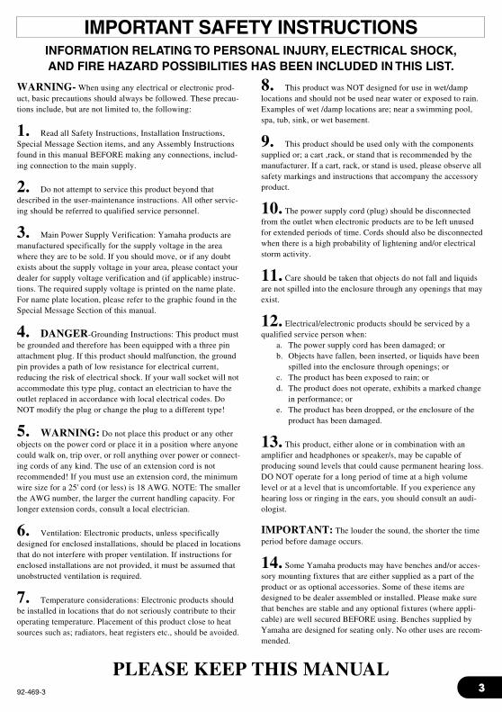
WARNING- When using any electrical or electronic prod-uct, basic precautions should always be followed. These precau-tions include, but are not limited to, the following:
1. Read all Safety Instructions, Installation Instructions,Special Message Section items, and any Assembly Instructionsfound in this manual BEFORE making any connections, includ-ing connection to the main supply.
2. Do not attempt to service this product beyond thatdescribed in the user-maintenance instructions. All other servic-ing should be referred to qualified service personnel.
3. Main Power Supply Verification: Yamaha products aremanufactured specifically for the supply voltage in the areawhere they are to be sold. If you should move, or if any doubtexists about the supply voltage in your area, please contact yourdealer for supply voltage verification and (if applicable) instruc-tions. The required supply voltage is printed on the name plate.For name plate location, please refer to the graphic found in theSpecial Message Section of this manual.
4. DANGER-Grounding Instructions: This product mustbe grounded and therefore has been equipped with a three pinattachment plug. If this product should malfunction, the groundpin provides a path of low resistance for electrical current,reducing the risk of electrical shock. If your wall socket will notaccommodate this type plug, contact an electrician to have theoutlet replaced in accordance with local electrical codes. DoNOT modify the plug or change the plug to a different type!
5. WARNING: Do not place this product or any otherobjects on the power cord or place it in a position where anyonecould walk on, trip over, or roll anything over power or connect-ing cords of any kind. The use of an extension cord is notrecommended! If you must use an extension cord, the minimumwire size for a 25' cord (or less) is 18 AWG. NOTE: The smallerthe AWG number, the larger the current handling capacity. Forlonger extension cords, consult a local electrician.
6. Ventilation: Electronic products, unless specificallydesigned for enclosed installations, should be placed in locationsthat do not interfere with proper ventilation. If instructions forenclosed installations are not provided, it must be assumed thatunobstructed ventilation is required.
7. Temperature considerations: Electronic products shouldbe installed in locations that do not seriously contribute to theiroperating temperature. Placement of this product close to heatsources such as; radiators, heat registers etc., should be avoided.
8. This product was NOT designed for use in wet/damplocations and should not be used near water or exposed to rain.Examples of wet /damp locations are; near a swimming pool,spa, tub, sink, or wet basement.
9. This product should be used only with the componentssupplied or; a cart ,rack, or stand that is recommended by themanufacturer. If a cart, rack, or stand is used, please observe allsafety markings and instructions that accompany the accessoryproduct.
10. The power supply cord (plug) should be disconnectedfrom the outlet when electronic products are to be left unusedfor extended periods of time. Cords should also be disconnectedwhen there is a high probability of lightening and/or electricalstorm activity.
11. Care should be taken that objects do not fall and liquidsare not spilled into the enclosure through any openings that mayexist.
12. Electrical/electronic products should be serviced by aqualified service person when:
a. The power supply cord has been damaged; orb. Objects have fallen, been inserted, or liquids have been
spilled into the enclosure through openings; orc. The product has been exposed to rain; ord. The product does not operate, exhibits a marked change
in performance; ore. The product has been dropped, or the enclosure of the
product has been damaged.
13. This product, either alone or in combination with anamplifier and headphones or speaker/s, may be capable ofproducing sound levels that could cause permanent hearing loss.DO NOT operate for a long period of time at a high volumelevel or at a level that is uncomfortable. If you experience anyhearing loss or ringing in the ears, you should consult an audi-ologist.
IMPORTANT: The louder the sound, the shorter the timeperiod before damage occurs.
14. Some Yamaha products may have benches and/or acces-sory mounting fixtures that are either supplied as a part of theproduct or as optional accessories. Some of these items aredesigned to be dealer assembled or installed. Please make surethat benches are stable and any optional fixtures (where appli-cable) are well secured BEFORE using. Benches supplied byYamaha are designed for seating only. No other uses are recom-mended.
INFORMATION RELATING TO PERSONAL INJURY, ELECTRICAL SHOCK,AND FIRE HAZARD POSSIBILITIES HAS BEEN INCLUDED IN THIS LIST.
IMPORTANT SAFETY INSTRUCTIONS
92-469-3
PLEASE KEEP THIS MANUAL
4
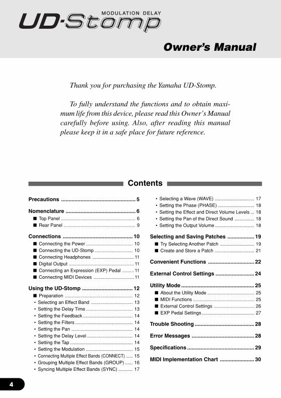
Thank you for purchasing the Yamaha UD-Stomp.
To fully understand the functions and to obtain maxi-mum life from this device, please read this Owner’s Manualcarefully before using. Also, after reading this manualplease keep it in a safe place for future reference.
Contents
Owner’s Manual
Precautions .................................................. 5
Nomenclature ............................................... 6 Top Panel ......................................................... 6 Rear Panel ....................................................... 9
Connections ............................................... 10 Connecting the Power .................................... 10 Connecting the UD-Stomp ............................. 10 Connecting Headphones ................................ 11 Digital Output .................................................. 11 Connecting an Expression (EXP) Pedal ......... 11 Connecting MIDI Devices ............................... 11
Using the UD-Stomp .................................. 12 Preparation .................................................... 12• Selecting an Effect Band ................................ 13• Setting the Delay Time .................................... 13• Setting the Feedback ...................................... 14• Setting the Filters ............................................ 14• Setting the Pan ............................................... 14• Setting the Delay Level ................................... 14• Setting the Tap ................................................ 14• Setting the Modulation .................................... 15• Connecting Multiple Effect Bands (CONNECT) ...... 15• Grouping Multiple Effect Bands (GROUP) ...... 16• Syncing Multiple Effect Bands (SYNC) ........... 17
• Selecting a Wave (WAVE) .............................. 17• Setting the Phase (PHASE) ............................ 18• Setting the Effect and Direct Volume Levels ... 18• Setting the Pan of the Direct Sound ............... 18• Setting the Output Volume .............................. 18
Selecting and Saving Patches .................. 19 Try Selecting Another Patch .......................... 19 Create and Store a Patch .............................. 21
Convenient Functions ............................... 22
External Control Settings .......................... 24
Utility Mode ................................................. 25 About the Utility Mode .................................... 25 MIDI Functions ............................................... 25 External Control Settings ............................... 26 EXP Pedal Settings ........................................ 27
Trouble Shooting ........................................ 28
Error Messages .......................................... 28
Specifications ............................................. 29
MIDI Implementation Chart ....................... 30

5
About the Backup Battery
A backup battery (lithium battery) is used to keep internal data (settings) from being lost, even whenthe power cord is unplugged. Internal data will be lost when battery power is depleted, so it is recom-mended that data be stored to an external data recorder such as the Yamaha MIDI Data Filer MDF3(→ page 26), or keep records of settings in memo form. The average battery life span is about 3years. When replacement becomes necessary contact the music store where the unit was pur-chased, or a qualified service representative, to perform the replacement.
• Do not attempt to replace the backup battery by yourself.
• Keep the backup battery out of reach of children.
• “E 5” appears in the display when the battery becomes depleted. Internal data may be lost.
• Data may be lost if the unit is improperly handled or if repairs are performed.
Precautions• Avoid using the UD-Stomp in the following locations to prevent possible damage:
• In direct sunlight or next to heating equipment.• In extremely cold or hot locations.• Locations exposed to high humidity or excessive dust.• Locations subject to strong shocks or vibration.
• Before making any connections, make sure that the power is switched OFF on the UD-Stompand any external devices.
• To protect speakers from possible damage, always set the OUTPUT knob to “0” before switchingthe power ON/OFF.
• When connecting any devices to this unit, make sure that the power is switched OFF first.
• Do not apply excessive force to the switches, knobs and controls.
• The UD-Stomp is a precision device. Handle it with care and avoid dropping or jarring it.
• Operating temperatures will rise during use. Make sure the UD-Stomp is used in a well-ventilatedare.
• For safety, always remove the power adaptor from the AC wall outlet if there is any danger oflightning striking in your area.
• Keep the UD-Stomp away from neon signs or fluorescent lighting to prevent noise pickup.
• To prevent damage and possibly electrical shock, never open the case and tamper with theinternal circuitry.
• Never use benzene, thinner or other volatile liquids for cleaning, as these chemicals may causedamage or discoloration to the finish. Always use a dry, soft cloth to wipe off dust and dirt.

6
q
w
t
e
r
Nomenclature Top Panel
Display & Main Section Controller Section
Footswitch Section
e Utility Button (UTILITY)Enters the Utility Mode. (→ page 25)
r Store Button (STORE)Enters the Store Mode. (→ page 21)
t DisplayDisplays memory numbers, parameter setting val-ues, etc.
q Up Button (UP)
w Down Button (DOWN)Press to change the Patch Number by +1/-1. Holdto change the Group Number by +1/-1. Simulta-neously press the [UP] and [DOWN] buttons toswitch between the USER ↔ PRESET Areas.Also, their flashing lamps are used to indicate therelationship between the patch data value and theknob’s position.
Display & Main Section
7
Nomenclature
Controller Section
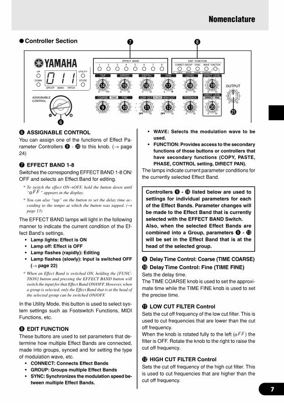
y ASSIGNABLE CONTROLYou can assign one of the functions of Effect Pa-rameter Controllers o - @0 to this knob. (→ page24)
u EFFECT BAND 1-8Switches the corresponding EFFECT BAND 1-8 ON/OFF and selects an Effect Band for editing.
* To switch the effect ON→OFF, hold the button down until“oFF” appears in the display.
* You can also “tap” on the button to set the delay time ac-cording to the tempo at which the button was tapped. (→page 13)
The EFFECT BAND lamps will light in the followingmanner to indicate the current condition of the Ef-fect Band’s settings.
• Lamp lights: Effect is ON• Lamp off: Effect is OFF• Lamp flashes (rapidly): Editing• Lamp flashes (slowly): Input is switched OFF
(→ page 22)
* When an Effect Band is switched ON, holding the [FUNC-TION] button and pressing the EFFECT BAND button willswitch the input for that Effect Band ON/OFF. However, whena group is selected, only the Effect Band that is at the head ofthe selected group can be switched ON/OFF.
In the Utility Mode, this button is used to select sys-tem settings such as Footswitch Functions, MIDIFunctions, etc.
i EDIT FUNCTIONThese buttons are used to set parameters that de-termine how multiple Effect Bands are connected,made into groups, synced and for setting the typeof modulation wave, etc.
• CONNECT: Connects Effect Bands• GROUP: Groups multiple Effect Bands• SYNC: Synchronizes the modulation speed be-
tween multiple Effect Bands.
• WAVE: Selects the modulation wave to beused.
• FUNCTION: Provides access to the secondaryfunctions of those buttons or controllers thathave secondary functions (COPY, PASTE,PHASE, CONTROL setting, DIRECT PAN).
The lamps indicate current parameter conditions forthe currently selected Effect Band.
Controllers o - !8 listed below are used tosettings for individual parameters for eachof the Effect Bands. Parameter changes willbe made to the Effect Band that is currentlyselected with the EFFECT BAND Switch.Also, when the selected Effect Bands arecombined into a Group, parameters o - !3
will be set in the Effect Band that is at thehead of the selected group.
o Delay Time Control: Coarse (TIME COARSE)
!0 Delay Time Control: Fine (TIME FINE)Sets the delay time.The TIME COARSE knob is used to set the approxi-mate time while the TIME FINE knob is used to setthe precise time.
!1 LOW CUT FILTER ControlSets the cut off frequency of the low cut filter. This isused to cut frequencies that are lower than the cutoff frequency.When the knob is rotated fully to the left (oFF) thefilter is OFF. Rotate the knob to the right to raise thecut off frequency.
!2 HIGH CUT FILTER ControlSets the cut off frequency of the high cut filter. Thisis used to cut frequencies that are higher than thecut off frequency.
y
u i
@1o !0 !1 !2 !3
!9!4 !5 !6 !7 !8
@0
8
@2 @3
When the knob is rotated fully to the left (oFF) thefilter is OFF. Rotate the knob to the right to lowerthe cut off frequency.
!3 FEEDBACK ControlSets the how many times the delay will repeat.
!4 TAP ControlSets the timing for when the delayed sound is takenfrom the delay loop.The value of the parameter is expressed as a per-centage of the delay time setting.
!5 SPEED ControlSets the speed of the modulation.When multiple Effect Bands are Synced together,this knob adjusts the phase angle.
!6 DEPTH ControlSets the intensity of the modulation.
!7 PAN ControlSets the position of the delay within the stereo field.
!8 Delay Level Control (LEVEL)Sets the output level of the delay.
* Rotating the knob fully to the left (0.0) mutes the delay sound.
Controllers !9 - @1 listed below are global pa-rameters for Effect Bands 1-8. They can beset at any time, even if no Effect Bands areselected.
!9 EFFECT LEVEL ControlSets the overall level of the signal sent to the effect.
@0 DIRECT LEVEL/DIRECT PAN ControlSets the output level of the direct sound.Hold the FUNCTION button and rotate this knob toset the stereo position of the direct sound.
@1 OUTPUT Level ControlControls the signal level that is sent from the UD-Stomp’s output jack (OUTPUT, PHONES).
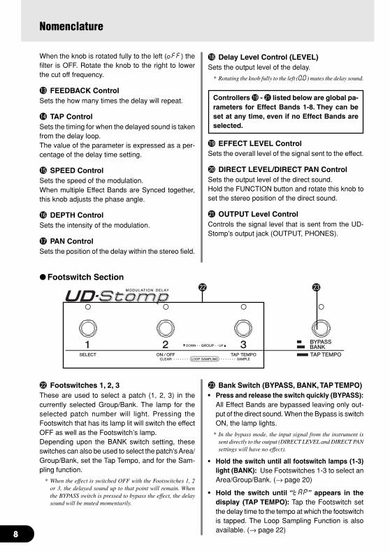
@2 Footswitches 1, 2, 3These are used to select a patch (1, 2, 3) in thecurrently selected Group/Bank. The lamp for theselected patch number will light. Pressing theFootswitch that has its lamp lit will switch the effectOFF as well as the Footswitch’s lamp.Depending upon the BANK switch setting, theseswitches can also be used to select the patch’s Area/Group/Bank, set the Tap Tempo, and for the Sam-pling function.
* When the effect is switched OFF with the Footswitches 1, 2or 3, the delayed sound up to that point will remain. Whenthe BYPASS switch is pressed to bypass the effect, the delaysound will be muted momentarily.
@3 Bank Switch (BYPASS, BANK, TAP TEMPO)• Press and release the switch quickly (BYPASS):
All Effect Bands are bypassed leaving only out-put of the direct sound. When the Bypass is switchON, the lamp lights.
* In the bypass mode, the input signal from the instrument issent directly to the output (DIRECT LEVEL and DIRECT PANsettings will have no effect).
• Hold the switch until all footswitch lamps (1-3)light (BANK): Use Footswitches 1-3 to select anArea/Group/Bank. (→ page 20)
• Hold the switch until “tAP” appears in thedisplay (TAP TEMPO): Tap the Footswitch setthe delay time to the tempo at which the footswitchis tapped. The Loop Sampling Function is alsoavailable. (→ page 22)
Footswitch Section
Nomenclature

9
@4 @5 @6 @7 @8 @9 #0 #3#2#1
Nomenclature
Rear Panel
@4 Power Switch (STAND-BY ON/OFF)Power switch for the main unit.
* To protect the speakers, set the OUTPUT knob @1 to “0”before switching the power ON/OFF.
@5 Power Adaptor Jack (AC IN 12V 1A)Connect the supplied power adaptor to this jack.
* Never use a power adaptor other than the supplied adaptor.Use of any other power adaptor may cause damage, over-heating, fire, etc.
@6 MIDI OUT JackThis jack is used for transmitting MIDI data from theUD-Stomp such as control changes, programchanges, data in the UD-Stomp’s memory, etc. (→page 26).
@7 MIDI IN JackThis jack is used for receiving MIDI data from a MIDIdevice, such as a MIDI foot controller, that can beused to select patches, volume, or control each ofthe effects in the UD-Stomp. (→ page 20)Also, UD-Stomp memory data saved to an externalMIDI device can be returned to the UD-Stomp viathis jack. (→ page 26)
@8 DIGITAL OUT JackThis Jack is used for sending the output of the UD-Stomp as digital data.Connect to a device equipped with a digital inputjack (COAXIAL) such as a digital mixer, etc. (→ page11).
@9 Expression Pedal Jack (EXP. PEDAL)This jack is used to connect a foot controller (ex-pression pedal) (optional) such as a Yamaha FC-7to control individual UD-Stomp parameters. (→ page24, 26, 27).
#0 Headphones Jack (PHONES)Connect a pair of headphones (optional) to this jackfor private practice or practicing at night when youdon’t want to disturb others. (→ page 11).
* Even when headphones are used, the audio signal isdelivered from the OUTPUT jack #1 and the DIGITALOUT jack @8.
#1 Output Jacks (OUTPUT R, L/MONO)The analog output jacks for the UD-Stomp. Con-nect these jacks to the input jack on a power ampli-fier + speaker set or guitar amp, mixer, etc. (→ page10)
* Use the L/MONO jack when connecting to a monaural de-vice.
#2 Input Level Switch (LOW/HIGH)
#3 INPUT JackThis is the UD-Stomp’s input jack. Connect a guitaror other electric musical instrument to this jack. Se-lect either HIGH or LOW to match UD-Stomp’s in-put jack to the output level of the instrument con-nected to the jack.
* Make sure the power is switched OFF before connecting theinstrument.
10
INPUT
EFFECTEFFECT
SENDRETURN
L R
OUTPUT
L/MONO R
Instrument
Guitar Amplifier, etc.
UD-Stomp
INPUT
INPUTL R
OUTPUT
L/MONO R
UD-Stomp
Instru-ment
Distortion, etc.
Connections
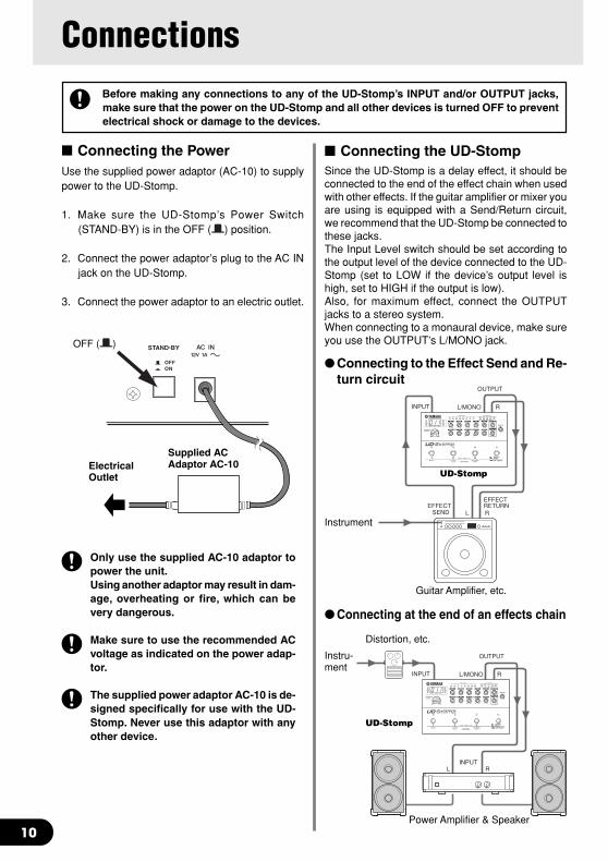
Connecting the PowerUse the supplied power adaptor (AC-10) to supplypower to the UD-Stomp.
1. Make sure the UD-Stomp’s Power Switch(STAND-BY) is in the OFF ( ) position.
2. Connect the power adaptor’s plug to the AC INjack on the UD-Stomp.
3. Connect the power adaptor to an electric outlet.
Only use the supplied AC-10 adaptor topower the unit.Using another adaptor may result in dam-age, overheating or fire, which can bevery dangerous.
Make sure to use the recommended ACvoltage as indicated on the power adap-tor.
The supplied power adaptor AC-10 is de-signed specifically for use with the UD-Stomp. Never use this adaptor with anyother device.
Before making any connections to any of the UD-Stomp’s INPUT and/or OUTPUT jacks,make sure that the power on the UD-Stomp and all other devices is turned OFF to preventelectrical shock or damage to the devices.
OFF ( )
Supplied ACAdaptor AC-10Electrical
Outlet
Connecting the UD-StompSince the UD-Stomp is a delay effect, it should beconnected to the end of the effect chain when usedwith other effects. If the guitar amplifier or mixer youare using is equipped with a Send/Return circuit,we recommend that the UD-Stomp be connected tothese jacks.The Input Level switch should be set according tothe output level of the device connected to the UD-Stomp (set to LOW if the device’s output level ishigh, set to HIGH if the output is low).Also, for maximum effect, connect the OUTPUTjacks to a stereo system.When connecting to a monaural device, make sureyou use the OUTPUT’s L/MONO jack.
Connecting to the Effect Send and Re-turn circuit
Connecting at the end of an effects chain
Power Amplifier & Speaker
11
Connections
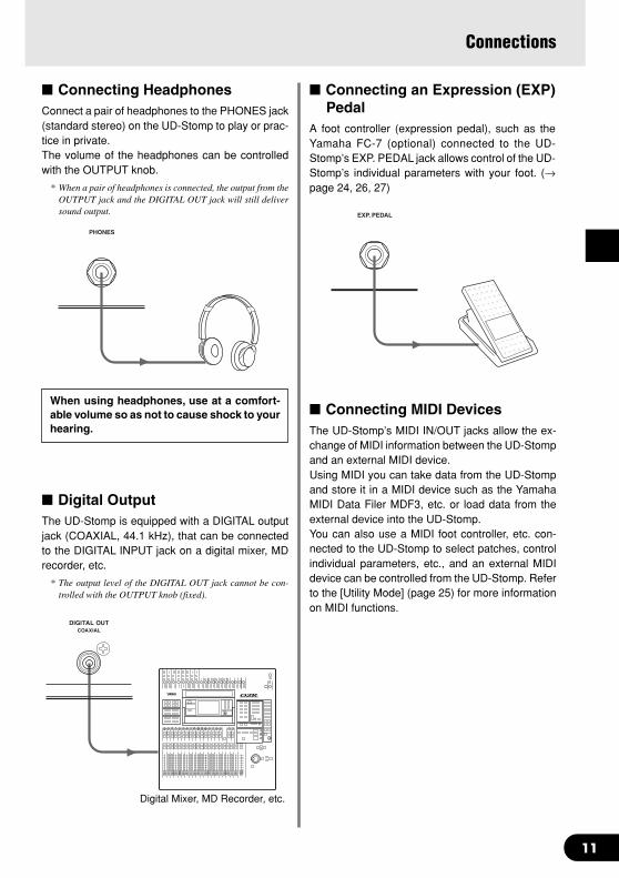
Connecting an Expression (EXP)Pedal
A foot controller (expression pedal), such as theYamaha FC-7 (optional) connected to the UD-Stomp’s EXP. PEDAL jack allows control of the UD-Stomp’s individual parameters with your foot. (→page 24, 26, 27)
Connecting HeadphonesConnect a pair of headphones to the PHONES jack(standard stereo) on the UD-Stomp to play or prac-tice in private.The volume of the headphones can be controlledwith the OUTPUT knob.
* When a pair of headphones is connected, the output from theOUTPUT jack and the DIGITAL OUT jack will still deliversound output.
When using headphones, use at a comfort-able volume so as not to cause shock to yourhearing.
Digital OutputThe UD-Stomp is equipped with a DIGITAL outputjack (COAXIAL, 44.1 kHz), that can be connectedto the DIGITAL INPUT jack on a digital mixer, MDrecorder, etc.
* The output level of the DIGITAL OUT jack cannot be con-trolled with the OUTPUT knob (fixed).
Digital Mixer, MD Recorder, etc.
Connecting MIDI DevicesThe UD-Stomp’s MIDI IN/OUT jacks allow the ex-change of MIDI information between the UD-Stompand an external MIDI device.Using MIDI you can take data from the UD-Stompand store it in a MIDI device such as the YamahaMIDI Data Filer MDF3, etc. or load data from theexternal device into the UD-Stomp.You can also use a MIDI foot controller, etc. con-nected to the UD-Stomp to select patches, controlindividual parameters, etc., and an external MIDIdevice can be controlled from the UD-Stomp. Referto the [Utility Mode] (page 25) for more informationon MIDI functions.
12
Using the UD-StompThe UD-Stomp is an effects processor that is equipped with eight identical delay circuits.It provides you with the power and freedom to create complex sounds by connecting multipledelay circuits in a series, or combine any or all of the individual circuits into a single, longdelay, etc.This section will use some of the UD-Stomp’s preset programs as examples to help you un-derstand how the parameters and functions work.
Preparation1. Connect your instrument, amplifier, a pair of
headphones, etc. to the UD-Stomp. (→ page 10,11)
Before making any connections, make surethat the power is switched OFF on all devices.
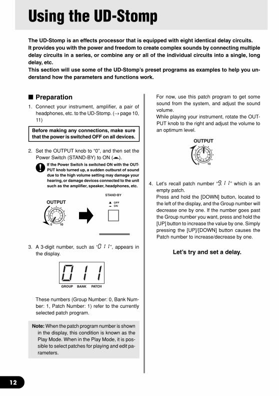
2. Set the OUTPUT knob to “0”, and then set thePower Switch (STAND-BY) to ON ( ).
If the Power Switch is switched ON with the OUT-PUT knob turned up, a sudden outburst of sounddue to the high volume setting may damage yourhearing, or damage devices connected to the unitsuch as the amplifier, speaker, headphones, etc.
3. A 3-digit number, such as “011”, appears inthe display.
These numbers (Group Number: 0, Bank Num-ber: 1, Patch Number: 1) refer to the currentlyselected patch program.
Note: When the patch program number is shownin the display, this condition is known as thePlay Mode. When in the Play Mode, it is pos-sible to select patches for playing and edit pa-rameters.
For now, use this patch program to get somesound from the system, and adjust the soundvolume.While playing your instrument, rotate the OUT-PUT knob to the right and adjust the volume toan optimum level.
4. Let’s recall patch number “9.11” which is anempty patch.Press and hold the [DOWN] button, located tothe left of the display, and the Group number willdecrease one by one. If the number goes pastthe Group number you want, press and hold the[UP] button to increase the value by one. Simplypressing the [UP]/[DOWN] button causes thePatch number to increase/decrease by one.
Let’s try and set a delay.
13
6 87
EFFECT BAND
Selecting an Effect Band
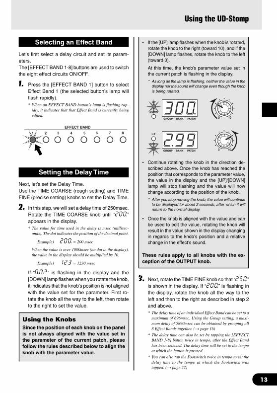
Let’s first select a delay circuit and set its param-eters.The [EFFECT BAND 1-8] buttons are used to switchthe eight effect circuits ON/OFF.
1. Press the [EFFECT BAND 1] button to selectEffect Band 1 (the selected button’s lamp willflash rapidly).* When an EFFECT BAND button’s lamp is flashing rap-
idly, it indicates that that Effect Band is currently beingedited.
Using the UD-Stomp
Setting the Delay Time
Next, let’s set the Delay Time.Use the TIME COARSE (rough setting) and TIMEFINE (precise setting) knobs to set the Delay Time.
2. In this step, we will set a delay time of 250msec.Rotate the TIME COARSE knob until “200.”appears in the display.* The value for time used in the delay is msec (millisec-
onds). The dot indicates the position of the decimal point.
Example) 200. = 200 msec
When the value is over 1000msec (no dot in the display),the value in the display should be multiplied by 10.
Example) 123 = 1230 msec
If “0.02” is flashing in the display and the[DOWN] lamp flashes when you rotate the knob,it indicates that the knob’s position is not alignedwith the value set for the parameter. First ro-tate the knob all the way to the left, then rotateto the right to set the value.
Using the KnobsSince the position of each knob on the panelis not always aligned with the value set inthe parameter of the current patch, pleasefollow the rules described below to align theknob with the parameter value.
• If the [UP] lamp flashes when the knob is rotated,rotate the knob to the right (toward 10), and if the[DOWN] lamp flashes, rotate the knob to the left(toward 0).
At this time, the knob’s parameter value set inthe current patch is flashing in the display.
* As long as the lamp is flashing, neither the value in thedisplay nor the sound will change even though the knobis being rotated.
• Continue rotating the knob in the direction de-scribed above. Once the knob has reached theposition that corresponds to the parameter value,the value in the display and the [UP]/[DOWN]lamp will stop flashing and the value will nowchange according to the position of the knob.
* After you stop moving the knob, the value will continueto be displayed for about 2 seconds, after which it willreturn to the normal display.
• Once the knob is aligned with the value and canbe used to edit the value, rotating the knob willresult in the value shown in the display changingin regards to the knob’s position and a relativechange in the effect’s sound.
These rules apply to all knobs with the ex-ception of the OUTPUT knob.
3. Next, rotate the TIME FINE knob so that “250.”is shown in the display. If “200.” is flashing inthe display, rotate the knob all the way to theleft and then to the right as described in step 2and above.* The delay time of an individual Effect Band can be set to a
maximum of 696msec. Using the Group setting, a maxi-mum delay of 5890msec can be obtained by grouping all8 Effect Bands together. (→ page 16)
* The delay time can also be set by tapping the [EFFECTBAND 1-8] button twice in tempo, after the Effect Bandhas been selected. The delay time will be set to the tempoat which the button is pressed.
* You can also tap the Footswitch twice in tempo to set thedelay time to the tempo at which the Footswitch wastapped. (→ page 22)
14
L R
PAN
L R
PAN
L R
PAN
Using the UD-Stomp
Setting the Feedback
Up to this point we have set the delay time so asingle delay sound is produced 250msec after theoriginal sound. Next, set the Feedback parameterto determine how many times the delay will repeat.
4. Rotate the FEEDBACK knob so that “10.0” ap-pears in the display. The delay sound is re-peated infinitely without fading out.When the FEEDBACK is set to a lower value,the number of times the delay is repeated willdecrease and the delay sound will fade out.In this step, set the FEEDBACK level to “5.0”.
Setting the Filters
The delay circuit also includes a HCF (High Cut Fil-ter) which, cuts high frequencies, and a LCF (LowCut Filter) which, cuts low frequencies. Since thesefilters are incorporated in the delay loop, the cuttingof the effected frequencies will be greater each timethe delay is repeated.
5. Rotate the LOW CUT FILTER knob or HIGHCUT FILTER knob and see how the filterschange the sound.* For both knobs, a setting of 10 (10.0) equals a cutoff
frequency of 1kHz and setting of 0 equals off (oFF).
* The cutoff is also applied to the first delay.
The use of these filters offers analog simulation, etc.Once you understand how the filters operate, setboth knobs to “oFF” and let’s move on to the nextstep.
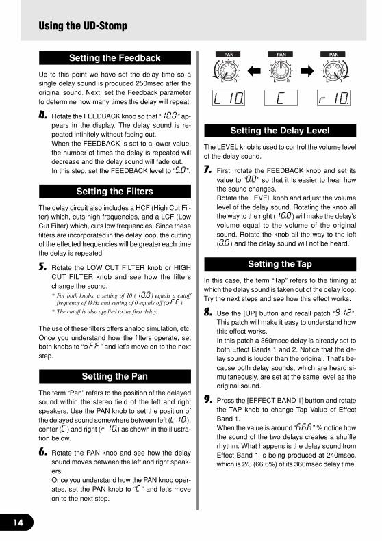
Setting the Pan
The term “Pan” refers to the position of the delayedsound within the stereo field of the left and rightspeakers. Use the PAN knob to set the position ofthe delayed sound somewhere between left (L10.),center (C) and right (r10.) as shown in the illustra-tion below.
6. Rotate the PAN knob and see how the delaysound moves between the left and right speak-ers.Once you understand how the PAN knob oper-ates, set the PAN knob to “C” and let’s moveon to the next step.
Setting the Delay Level
The LEVEL knob is used to control the volume levelof the delay sound.
7. First, rotate the FEEDBACK knob and set itsvalue to “0.0” so that it is easier to hear howthe sound changes.Rotate the LEVEL knob and adjust the volumelevel of the delay sound. Rotating the knob allthe way to the right (10.0) will make the delay’svolume equal to the volume of the originalsound. Rotate the knob all the way to the left(0.0) and the delay sound will not be heard.
Setting the Tap
In this case, the term “Tap” refers to the timing atwhich the delay sound is taken out of the delay loop.Try the next steps and see how this effect works.
8. Use the [UP] button and recall patch “9.12”.This patch will make it easy to understand howthis effect works.In this patch a 360msec delay is already set toboth Effect Bands 1 and 2. Notice that the de-lay sound is louder than the original. That’s be-cause both delay sounds, which are heard si-multaneously, are set at the same level as theoriginal sound.
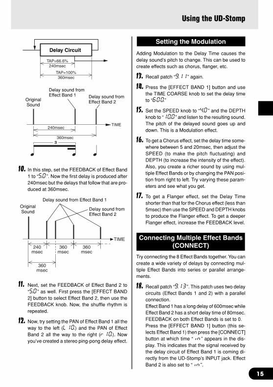
9. Press the [EFFECT BAND 1] button and rotatethe TAP knob to change Tap Value of EffectBand 1.When the value is around “66.6” % notice howthe sound of the two delays creates a shufflerhythm. What happens is the delay sound fromEffect Band 1 is being produced at 240msec,which is 2/3 (66.6%) of its 360msec delay time.
15
240msec
360msec
360msec
360msec
TIME
OriginalSound
Delay sound from Effect Band 1
Delay sound fromEffect Band 2
OriginalSound
Delay sound fromEffect Band 1 Delay sound from
Effect Band 2
360msecTAP=100%
240msecTAP=66.6%
Delay Circuit
10. In this step, set the FEEDBACK of Effect Band1 to “5.0”. Now the first delay is produced after240msec but the delays that follow that are pro-duced at 360msec.
TIME240msec
360msec
11. Next, set the FEEDBACK of Effect Band 2 to“5.0” as well. First press the [EFFECT BAND2] button to select Effect Band 2, then use theFEEDBACK knob. Now, the shuffle rhythm isrepeated.
12. Now, try setting the PAN of Effect Band 1 all theway to the left (L10.) and the PAN of EffectBand 2 all the way to the right (r10.). Nowyou’ve created a stereo ping-pong delay effect.
Setting the Modulation
Adding Modulation to the Delay Time causes thedelay sound’s pitch to change. This can be used tocreate effects such as chorus, flanger, etc.
13. Recall patch “9.11” again.
14. Press the [EFFECT BAND 1] button and usethe TIME COARSE knob to set the delay timeto “600.”
15. Set the SPEED knob to “4.0” and the DEPTHknob to “10.0” and listen to the resulting sound.The pitch of the delayed sound goes up anddown. This is a Modulation effect.
16. To get a Chorus effect, set the delay time some-where between 5 and 20msec, then adjust theSPEED (to make the pitch fluctuating) andDEPTH (to increase the intensity of the effect).Also, you create a richer sound by using mul-tiple Effect Bands or by changing the PAN posi-tion from right to left. Try varying these param-eters and see what you get.
17. To get a Flanger effect, set the Delay Timeshorter than that for the Chorus effect (less than5msec) then use the SPEED and DEPTH knobsto produce the Flanger effect. To get a deeperFlanger effect, increase the FEEDBACK level.
Connecting Multiple Effect Bands(CONNECT)
Try connecting the 8 Effect Bands together. You cancreate a wide variety of delays by connecting mul-tiple Effect Bands into series or parallel arrange-ments.
18. Recall patch “9.13”. This patch uses two delaycircuits (Effect Bands 1 and 2) with a parallelconnection.Effect Band 1 has a long delay of 600msec whileEffect Band 2 has a short delay time of 80msec.FEEDBACK on both Effect Bands is set to 0.Press the [EFFECT BAND 1] button (this se-lects Effect Band 1) then press the [CONNECT]button at which time “in” appears in the dis-play. This indicates that the signal received bythe delay circuit of Effect Band 1 is coming di-rectly from the UD-Stomp’s INPUT jack. EffectBand 2 is also set to “in”.
Using the UD-Stomp
16
BAND 1 BAND 2696msec 696msec
BAND 1-21430msec
Delay Output Delay Output
Delay Output Delay Output
BAND 1IN 1 BAND 4 4 BAND 7
BAND 8IN 8 BAND 5 5 BAND 2
BAND 3IN 3 BAND 6
BAND 1IN
BAND 2IN
BAND 3IN
BAND 4IN
BAND 5IN
BAND 6IN
BAND 7IN
BAND 8IN
BAND 1IN 1 BAND 2 7 BAND 8BAND 3~7
BAND 4IN
4 BAND 2
4 BAND 3
2 BAND 5
2 BAND 6
3 BAND 7
3 BAND 8
BAND 1IN
BAND 1IN
IN BAND 2
BAND 1IN 1 BAND 2
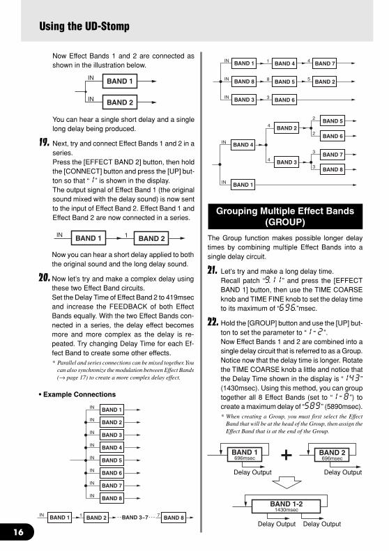
Now Effect Bands 1 and 2 are connected asshown in the illustration below.
Using the UD-Stomp
You can hear a single short delay and a singlelong delay being produced.
19. Next, try and connect Effect Bands 1 and 2 in aseries.Press the [EFFECT BAND 2] button, then holdthe [CONNECT] button and press the [UP] but-ton so that “1” is shown in the display.The output signal of Effect Band 1 (the originalsound mixed with the delay sound) is now sentto the input of Effect Band 2. Effect Band 1 andEffect Band 2 are now connected in a series.
Now you can hear a short delay applied to boththe original sound and the long delay sound.
20. Now let’s try and make a complex delay usingthese two Effect Band circuits.Set the Delay Time of Effect Band 2 to 419msecand increase the FEEDBACK of both EffectBands equally. With the two Effect Bands con-nected in a series, the delay effect becomesmore and more complex as the delay is re-peated. Try changing Delay Time for each Ef-fect Band to create some other effects.* Parallel and series connections can be mixed together. You
can also synchronize the modulation between Effect Bands(→ page 17) to create a more complex delay effect.
• Example Connections
Grouping Multiple Effect Bands(GROUP)
The Group function makes possible longer delaytimes by combining multiple Effect Bands into asingle delay circuit.
21. Let’s try and make a long delay time.Recall patch “9.11” and press the [EFFECTBAND 1] button, then use the TIME COARSEknob and TIME FINE knob to set the delay timeto its maximum of “696.”msec.
22. Hold the [GROUP] button and use the [UP] but-ton to set the parameter to “1-2”.Now Effect Bands 1 and 2 are combined into asingle delay circuit that is referred to as a Group.Notice now that the delay time is longer. Rotatethe TIME COARSE knob a little and notice thatthe Delay Time shown in the display is “143”(1430msec). Using this method, you can grouptogether all 8 Effect Bands (set to “1-8”) tocreate a maximum delay of “589” (5890msec).* When creating a Group, you must first select the Effect
Band that will be at the head of the Group, then assign theEffect Band that is at the end of the Group.

17
Also, once a Group has been set, you can accessany of the outputs from the individual delay unitsthat make up the group.
23. Confirm that Effect Bands 1 and 2 are still com-bined into a Group (1-2) as explained above.Next, press the [EFFECT BAND 2] button toswitch ON Effect Band 2. Since Effect Bands 1and 2 the same delay time, two delay sounds,of the same level, can be heard simultaneously.Using the same technique as explained in the“Setting the Tap” section (→ page 14) use theTAP knob to create a shuffle rhythm. You canalso use the PAN knob to create a ping-pongdelay effect. The difference between the TAPsetting and the previous one is that in this step,changing the Delay Time lets you alter thetempo of the shuffle rhythm without changingthe rhythm itself.Now press the [EFFECT BAND 1] button androtate the TIME FINE knob and listen to whathappens.Patch “9.21” produces a 16-beat type effectthat can also be set to different tempos for keep-ing rhythm.* When Effect Bands are combined into a Group, TIME
COARSE/FINE, FILTER LOW CUT/HIGH CUT andFEEDBACK knob settings are applied to the lowest num-bered Effect Band in the Group.
Syncing Multiple Effect Bands(SYNC)
When modulation is used in multiple delays, theSYNC function let’s you sync the modulation speedof multiple delay bands.
24. Recall patch number “9.22”This patch uses two Effect Bands; one pannedleft the other right and each using a monauralchorus effect with synchronized modulation.In this patch, the modulation of Effect Band 2 issynchronized with Effect Band 1. Let’s switchthe synchronization OFF in Effect Band 2 andsee what happens.
25. Select Effect Band 2 then hold the [SYNC] but-ton and use the [UP] button to set the value inthe display to “2”. This indicates that Effect Band2 is synchronized with Effect Band 2 and nolonger synchronized to another Effect Band.In this condition, the modulation can be heard
in the left channel but not in the right becauseEffect Band 2’s SPEED setting is set to “0.0”.Try setting the SYNC again.
26. Hold the [SYNC] button and press the [DOWN]button to set the value in the display to “1”. Nowthe modulation in Effect Band 2 is synchronizedwith the modulation in Effect Band 1.When the modulation is synchronized, theSPEED knob can be used to create differencesin the phase between the synchronized bands.Rotating the SPEED knob creates a greater ste-reo effect. At this time the modulation speed isthe same. The difference in their phase can beset between greater than 0° and less than 360°.Setting the SPEED knob to “5.0” creates a re-verse phase (180°). After setting the SPEED to“5.0”, next select Effect Band 1 and rotate theSPEED knob and in this reverse phase condi-tion, the speed can be changed simultaneouslyin both left and right sides.
Selecting a Wave (WAVE)
When the delay uses modulation, you can choosethe wave that is used in the modulation.
27. Recall patch number “9.23”.The sound in the left channel of this patch os-cillates. This heavy modulation uses a sinewave. Let’s try changing the wave type.
28. Select Effect Band 1 then holding the [WAVE]button, press the [UP]/[DOWN] buttons andcompare the difference between the four wavesdescribed below.* The [WAVE] + [UP] buttons select progress through the
waves in the following order,
tri → S.UP → S.dn → tri.
The [WAVE] + [DOWN] buttons select Sin.
• Sin… .. A sine wave. The pitch goessmoothly up and down followingthe curve of a sine wave.
• tri… .. A triangle wave. The pitch jumpsup and down.
• S.UP… .. Saw Up. Raises the pitch.• S.dn… .. Saw Down. Lowers the pitch.
Using the UD-Stomp
18
Two modulation waves (sine plus one more) canbe used at the same time. Press the [EFFECTBAND 2] button to switch Effect Band 2 ON,and you’ll hear the sine wave modulation onthe right channel while the other wave typemodulation is heard on the left.
Setting the Phase (PHASE)
When mixing the delay sound with the direct sound,the phase can be set to normal or reverse. Mixingthe direct sound with the sound of the delay with itsphase reversed is a good way to create an imageof spaciousness with the sound.
29. Recall patch number “9.22”After selecting Effect Band 1, hold the [FUNC-TION] button and the [SYNC] button, and pressthe [UP]/[DOWN] buttons to set either “rEu”(Reverse: reverse phase) or “nor” (Normal:normal phase) and listen to how the soundchanges.
Setting the Effect and DirectVolume Levels
The EFFECT LEVEL knob is used to set the vol-ume level of the delay sound.The DIRECT LEVEL knob is used to set the volumelevel of the direct sound.
30. Recall patch number “9.21”.Set the EFFECT LEVEL knob to “0.0” and theDIRECT LEVEL knob to “10.0”. Only the di-rect sound is produced.
31. Next, set the EFFECT LEVEL knob to “10.0”and the DIRECT LEVEL knob to “0.0”. Now thedelay sound is produced and the direct soundis not.These two knobs are used to control the soundbalance between the direct sound and the de-lay sound.* The EFFECT LEVEL knob is used to set the level of the
signal that is sent to the connected or grouped EffectBands.
* Both the EFFECT LEVEL and DIRECT LEVEL knobscan also be set when an Effect Band is not selected.
Setting the Pan of the Direct Sound
The DIRECT PAN knob is used to set the directsound’s position within the stereo field.
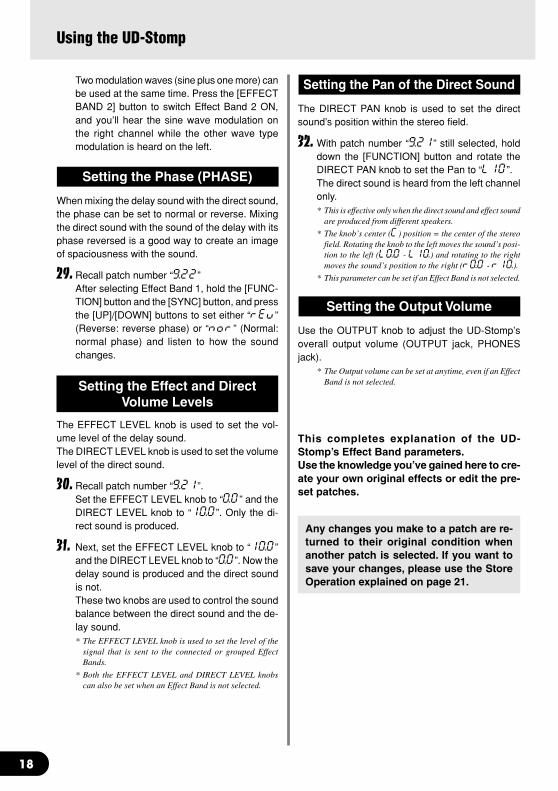
32. With patch number “9.21” still selected, holddown the [FUNCTION] button and rotate theDIRECT PAN knob to set the Pan to “L10”.The direct sound is heard from the left channelonly.* This is effective only when the direct sound and effect sound
are produced from different speakers.
* The knob’s center (C) position = the center of the stereofield. Rotating the knob to the left moves the sound’s posi-tion to the left (L0.0 - L10.) and rotating to the rightmoves the sound’s position to the right (r0.0 - r10.).
* This parameter can be set if an Effect Band is not selected.
Setting the Output Volume
Use the OUTPUT knob to adjust the UD-Stomp’soverall output volume (OUTPUT jack, PHONESjack).
* The Output volume can be set at anytime, even if an EffectBand is not selected.
This completes explanation of the UD-Stomp’s Effect Band parameters.Use the knowledge you’ve gained here to cre-ate your own original effects or edit the pre-set patches.
Using the UD-Stomp
Any changes you make to a patch are re-turned to their original condition whenanother patch is selected. If you want tosave your changes, please use the StoreOperation explained on page 21.
19
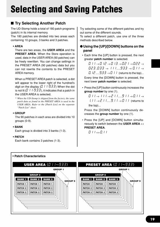
Selecting and Saving Patches Try Selecting Another PatchThe UD-Stomp holds a total of 180 patch programs(patch) in its internal memory.The 180 patches are divided into two areas eachcontaining 10 groups, 3 banks and 3 patches.
• AREAThere are two areas, the USER AREA and thePRESET AREA. When the Store operation isused, data in the USER AREA (90 patches) canbe freely rewritten. You can change settings inthe PRESET AREA (90 patches) data but youcan not rewrite the contents to the PRESETAREA memory.
When a PRESET AREA patch is selected, a dotwill appear to the lower right of the hundred’sdigit on the display (0.11-9.33) When the dotis not lit (011-933), it indicates that a patch inthe USER AREA is selected.* When the UD-Stomp is shipped from the factory, the same
patch data as found in the PRESET AREA is used in theUSER AREA. Refer to the [Patch List] on the separate“Patch List” sheet.
• GROUPThe 90 patches in each area are divided into 10groups (0-9).
• BANKEach group is divided into 3 banks (1-3).
• PATCHEach bank contains 3 patches (1-3).
Try selecting some of the different patches and tryout some of the different sounds.To select a different patch, use one of the threemethods described below.
Using the [UP]/[DOWN] buttons on thepanel
• Each time the [UP] button is pressed, the nextgreater patch number is selected.
011 → 012 → 013 → 021 → 022 →023..033 → 111.....933 → 0.11 →0.12.....9.33 → 011 (returns to the top)...
Every time the [DOWN] button is pressed, thenext lower patch number is selected.
• Press the [UP] button continuously increases thegroup number by one (1).
011 → 111 → 211.....911 → 0.11 →1.11 → 2.11.....9.11 → 011 (returns to
the top)...
Press the [DOWN] button continuously de-creases the group number by one (1).
• Press the [UP] and [DOWN] button simulta-neously to switch between the USER AREA ↔PRESET AREA.
011 ↔ 0.11
• Patch Characteristics
20
Using the Foot Switch and the BankSwitch
• Press a foot switch (1-3) to select the corre-sponding patch number 1-3 in the currently se-lected group/bank.
• Press and hold the BANK switch until all footswitch lamps (1-3) light then remove your foot.In this condition, the following procedure can beused.
1. Hold Foot Switch 1 for more than one second toswitch between the USER AREA ↔ PRESETAREA.
2. Hold Foot Switch 2 for more than one second todecrease the group number by a value of one.
3. Hold Foot Switch 3 for more than one second toincrease the group number by a value of one.
4. Press a Foot Switch (1-3) to select the corre-sponding bank number (1-3).
5. When a BANK is selected, the lamp in the dis-play and foot switch lamp will flash quickly. Pressa Foot Switch (1-3) at this time to select the cor-responding patch number (1-3).
* To cancel the selected patch, press the BANK switch. It willreturn to the previous condition.
Selecting and Saving Patches
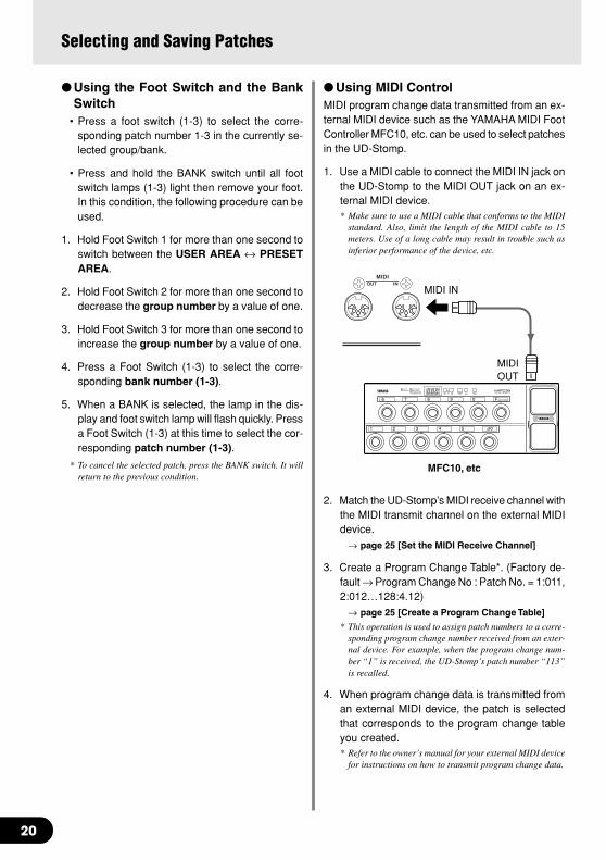
Using MIDI ControlMIDI program change data transmitted from an ex-ternal MIDI device such as the YAMAHA MIDI FootController MFC10, etc. can be used to select patchesin the UD-Stomp.
1. Use a MIDI cable to connect the MIDI IN jack onthe UD-Stomp to the MIDI OUT jack on an ex-ternal MIDI device.* Make sure to use a MIDI cable that conforms to the MIDI
standard. Also, limit the length of the MIDI cable to 15meters. Use of a long cable may result in trouble such asinferior performance of the device, etc.
2. Match the UD-Stomp’s MIDI receive channel withthe MIDI transmit channel on the external MIDIdevice.
→ page 25 [Set the MIDI Receive Channel]
3. Create a Program Change Table*. (Factory de-fault → Program Change No : Patch No. = 1:011,2:012…128:4.12)
→ page 25 [Create a Program Change Table]
* This operation is used to assign patch numbers to a corre-sponding program change number received from an exter-nal device. For example, when the program change num-ber “1” is received, the UD-Stomp’s patch number “113”is recalled.
4. When program change data is transmitted froman external MIDI device, the patch is selectedthat corresponds to the program change tableyou created.* Refer to the owner’s manual for your external MIDI device
for instructions on how to transmit program change data.
MIDI IN
MIDIOUT
MFC10, etc

21
Selecting and Saving Patches
Create and Store a PatchOriginal settings can be stored in the USER AREA(011-933). Try creating an original patch and thenstore it.
Storing Procedure1. Press the [STORE] button.
When you enter the Store Mode, the display, the[STORE] lamp and the foot switch lamp corre-sponding to the patch number will flash.
2. Select the patch (group, bank, patch number) towhich you want to store the patch.
Use the same procedure as described in [TrySelecting Another Patch] (page 19) to select apatch. You can use the [UP]/[DOWN] buttons, thefoot switches and the BANK switch to select thepatch number. However, you cannot change theAREA (it can only be assigned to the USERAREA).
3. After select the patch you want to store yourpatch in, hold the [STORE] button.The store operation is complete when all lampslight.
* To interrupt the Store operation, quickly press and releasethe [STORE] button.
* Utility mode settings are not stored with patch data. As com-mon settings for all patches, their contents are stored in theUD-Stomp memory.
* The OUTPUT knob’s setting is not stored with the patch data.
* Data in the USER AREA (011-933) can be stored in an exter-nal MIDI device. (→ page 26)
* MIDI cannot be received while storing.
This procedure can be used to store original patchesand also used to rearrange the order of patches foruse during live performance.
22
Convenient FunctionsHere are some convenient functions that make using the UD-Stomp easier.
Use the Footswitch to set the DelayTime (Tap Tempo)
With the UD-Stomp you can tap on the Footswitchto set the Delay Time parameter.
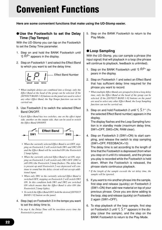
1. Step on and hold the BANK Footswitch until“tAP” appears in the display.
2. Step on Footswitch 1 and select the Effect Bandto which you want to set the delay time.
* When multiple delays are combined into a Group, only theEffect Band at the head of the group can be selected. If the[EFFECT BAND 1-8] buttons on the panel are used to selectany other Effect Band, the Tap Tempo function can not becarried out.
3. Use Footswitch 2 to switch the selected EffectBand ON/OFF.
* Each Effect Band has two switches, one on the effect inputside, another on the output side, that can be used to switchthe Effect Band ON/OFF.
• When the currently selected Effect Band is set OFF, step-ping on Footswitch 2 will switch both SW1 and SW2 ONand the Effect Band will be switched ON (the Footswitch2 lamp lights).
• When the currently selected Effect Band is set ON, step-ping on Footswitch 2 will switch only SW1 OFF (SW2 isstill ON) (the Footswitch 2 lamp flashes). The delay thatis present up until Footswitch 2 was depressed will con-tinue to sound but the delay circuit will not accept addi-tional input.
• When only SW1 in the currently selected Effect Band isswitched OFF, stepping on Footswitch 2 will switch SW1ON. In this condition both SW1 and SW2 are switchedON which means that the Effect Band is also ON (theFootswitch 2 lamp lights).
• To switch the Effect Band OFF, hold the desired [EFFECTBAND 1-8] button on the panel.
4. Step (tap) on Footswitch 3 in the tempo you wantto set the delay time to.
* In step 4, the Delay Time will be rewritten every time theFootswitch is pressed.
Effect Band Number
Effect BandSW1 SW2
5. Step on the BANK Footswitch to return to thePlay Mode.
Loop SamplingWith the UD-Stomp, you can sample a phrase (theinput signal) that will playback in a loop (the phrasewill continue to playback, feedback is unlimited).
1. Step on the BANK Footswitch until “tAP” ap-pears in the display.
2. Step on Footswitch 1 and select an Effect Bandthat has sufficient delay time required for thephrase you want to record.
* When multiple Effect Bands are grouped to form a long delaytime, only the Effect Band at the head of the group can beselected. If the [EFFECT BAND 1-8] buttons on the panelare used to select any other Effect Band, the Loop Samplingfunction can not be carried out.
3. Step on and hold Footswitch 2 until “LS.? ” (?=the selected Effect Band number) appears in thedisplay.The display flashes and the Loop Sampling func-tion is in standby mode (maximum delay time,SW1=OFF, SW2=ON, RAM clear).
4. Step on Footswitch 3 (SW1=ON) to start sam-pling, and release the switch to stop sampling(SW1=OFF, FEEDBACK=10)The delay time is set according to the length oftime that the Footswitch is depressed (from whenyou step on it until it’s released), and the phraseyou play is recorded while the Footswitch is helddown. When the Footswitch is released, thephrase starts continuous playback.
* If the length of the sample exceeds the set delay time, thesample will be ignored.
5. If you want to mix another phrase into the sample,first step and release (quickly) on Footswitch 2(SW1=ON) then add new material on top of yourprevious phrase. Once you are done adding tothe loop, step and release (quickly) on Footswitch2 again (SW1=OFF).
6. To stop playback of the loop sample, first stepon Footswitch 2 until “LS.? ” appears in the dis-play (clear the sample), and the step on theBANK Footswitch to return to the Play Mode.
23
* If you want to stop loop sample playback temporarily, stepon the BANK Footswitch to enter the Bypass Mode. To restartloop sample playback, press the BANK Footswitch again.
* The sample loop can also be cleared by setting the FEED-BACK knob to “0” or using the [EFFECT BAND 1-8] but-tons switch the Effect Band OFF.
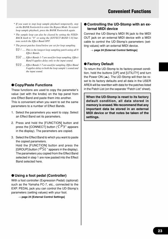
* The preset patches listed below are set for loop sampling.
9.31 ..... This is the longest loop sampling patch using all 8Effect Bands.
9.32 ..... Effect Bands 1-7 are used for loop sampling. EffectBand 8 applies delay only to the input sound.
9.33 ..... Effect Bands 1-7 are used for sampling. Effect Band8 applies delay to both the loop sample’s sound andthe input sound.
Copy/Paste FunctionsThese functions are used to copy the parameter’svalue (set with the knobs) on the top panel fromone Effect Band and paste them into another.This is convenient when you want to set the sameparameters to a number of Effect Bands.
1. Select the parameters you want to copy. Selectan Effect Band set its parameters.
2. Press and hold the [FUNCTION] button andpress the [CONNECT] button (“CPY” appearsin the display). The parameters are copied.
3. Select the Effect Band to which you want to pastethe copied parameters.Hold the [FUNCTION] button and press the[GROUP] button (“PSt” appears in the display).The parameters you copied from the Effect Bandselected in step 1 are now pasted into the EffectBand selected here.
Using a foot pedal (Controller)With a foot controller (Expression Pedal) (optional)such as the Yamaha FC-7, etc., connected to theEXP. PEDAL jack you can control the UD-Stomp’sparameters (setting values) with your foot.
→ page 24 [External Control Settings]
Controlling the UD-Stomp with an ex-ternal MIDI device
Connect the UD-Stomp’s MIDI IN jack to the MIDIOUT jack on an external MIDI device with a MIDIcable to control the UD-Stomp’s parameters (set-ting values) with an external MIDI device.
→ page 24 [External Control Settings]
Factory DefaultTo return the UD-Stomp to its factory-preset condi-tion, hold the buttons [UP] and [UTILITY] and turnthe Power ON ( ). The UD-Stomp will then be re-set to its factory defaults and all data in the USERAREA will be rewritten with data for the patches listedin the Patch List (on the separate “Patch List” sheet).
When the UD-Stomp is reset to its factorydefault condition, all data stored inmemory is erased. We recommend that anyimportant data be stored in an externalMIDI device or that notes be taken of thesettings.
Convenient Functions
24
External Control Settings
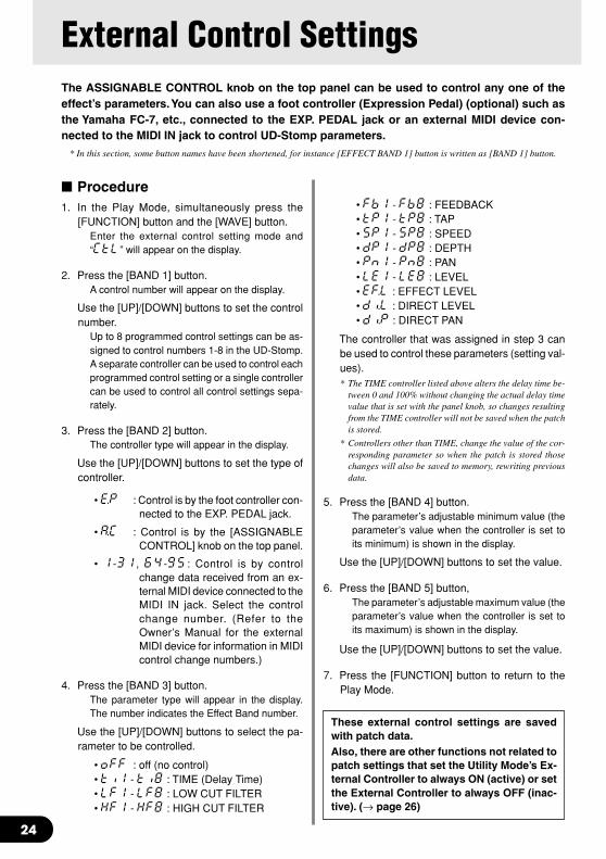
• Fb1 - Fb8 : FEEDBACK• tP1 - tP8 : TAP• SP1 - SP8 : SPEED• dP1 - dP8 : DEPTH• Pn1 - Pn8 : PAN• LE1 - LE8 : LEVEL• EF.L : EFFECT LEVEL• di.L : DIRECT LEVEL• di.P : DIRECT PAN
The controller that was assigned in step 3 canbe used to control these parameters (setting val-ues).* The TIME controller listed above alters the delay time be-
tween 0 and 100% without changing the actual delay timevalue that is set with the panel knob, so changes resultingfrom the TIME controller will not be saved when the patchis stored.
* Controllers other than TIME, change the value of the cor-responding parameter so when the patch is stored thosechanges will also be saved to memory, rewriting previousdata.
5. Press the [BAND 4] button.The parameter’s adjustable minimum value (theparameter’s value when the controller is set toits minimum) is shown in the display.
Use the [UP]/[DOWN] buttons to set the value.
6. Press the [BAND 5] button,The parameter’s adjustable maximum value (theparameter’s value when the controller is set toits maximum) is shown in the display.
Use the [UP]/[DOWN] buttons to set the value.
7. Press the [FUNCTION] button to return to thePlay Mode.
The ASSIGNABLE CONTROL knob on the top panel can be used to control any one of theeffect’s parameters. You can also use a foot controller (Expression Pedal) (optional) such asthe Yamaha FC-7, etc., connected to the EXP. PEDAL jack or an external MIDI device con-nected to the MIDI IN jack to control UD-Stomp parameters.
* In this section, some button names have been shortened, for instance [EFFECT BAND 1] button is written as [BAND 1] button.
Procedure1. In the Play Mode, simultaneously press the
[FUNCTION] button and the [WAVE] button.Enter the external control setting mode and“CtL” will appear on the display.
2. Press the [BAND 1] button.A control number will appear on the display.
Use the [UP]/[DOWN] buttons to set the controlnumber.
Up to 8 programmed control settings can be as-signed to control numbers 1-8 in the UD-Stomp.A separate controller can be used to control eachprogrammed control setting or a single controllercan be used to control all control settings sepa-rately.
3. Press the [BAND 2] button.The controller type will appear in the display.
Use the [UP]/[DOWN] buttons to set the type ofcontroller.
• E.P : Control is by the foot controller con-nected to the EXP. PEDAL jack.
• A.C : Control is by the [ASSIGNABLECONTROL] knob on the top panel.
• 1-31, 64-95 : Control is by controlchange data received from an ex-ternal MIDI device connected to theMIDI IN jack. Select the controlchange number. (Refer to theOwner’s Manual for the externalMIDI device for information in MIDIcontrol change numbers.)
4. Press the [BAND 3] button.The parameter type will appear in the display.The number indicates the Effect Band number.
Use the [UP]/[DOWN] buttons to select the pa-rameter to be controlled.
• oFF : off (no control)• ti1 - ti8 : TIME (Delay Time)• LF1 - LF8 : LOW CUT FILTER• HF1 - HF8 : HIGH CUT FILTER
These external control settings are savedwith patch data.Also, there are other functions not related topatch settings that set the Utility Mode’s Ex-ternal Controller to always ON (active) or setthe External Controller to always OFF (inac-tive). (→ page 26)

25
Utility ModeThe Utility Mode is used for settings that cover the overall system of the UD-Stomp such asthe foot switch, MIDI, external control, EXP. pedal jack, etc.
* In this section, some button names have been shortened, for instance [EFFECT BAND 1] button is written as [BAND 1] button.
ted from the UD-Stomp’s MIDI OUT jack to a con-trol an external effector, etc. from the UD-Stomp.Assigns to the patch, a MIDI PRG No. that will betransmitted when the patch is recalled.
* When a patch is recalled with a MIDI program change com-mand, MIDI PRG. Numbers can not be transmitted.
Press the [BAND 3] button to set the UD-Stomp’spatch number. Just as in selecting a patch in thePlay Mode, use the [UP]/[DOWN] buttons or thefootswitch.
• 011-933, 0.11-9.33 :The patch number to be recalled.
Press the [BAND 4] button to set the MIDI PRG No.to be transmitted. Use the [UP]/[DOWN] buttons toselect the number.
• 1-128 : MIDI Program Change No.
Set the MIDI Receive ChannelSets the UD-Stomp’s MIDI Receive Channel.The MIDI channel set in this step is also used asthe device number for the bulk receive function.
Press the [BAND 5] button and use the [UP]/[DOWN]buttons to set the MIDI receive channel.
• 1-16 : MIDI channel over which messages arereceived.
• ALL : MIDI messages from all channels arereceived
• oFF : MIDI messages are not received
Set the MIDI Transmit ChannelSets the UD-Stomp’s MIDI Transmit Channel.The MIDI channel set in this step is also used asthe device number for the bulk out function.
Press the [BAND 6] button and use the [UP]/[DOWN]buttons to set the MIDI transmit channel.
• 1-16 : MIDI channel over which messages aretransmitted.
ON/OFF Setting for MIDI MergeSets whether or not the MIDI signal that is receivedvia the UD-Stomp’s MIDI IN jack will also be retrans-mitted via the MIDI OUT jack.
About the Utility ModeWhen in the Play Mode, press the [UTILITY] buttonto enter the Utility Mode (the lamp lights).When in the Utility Mode press the [UTILITY] buttonto return to the Play Mode (the lamp goes off).
When in the Utility Mode MIDI messages cannot be received. Use the Play Mode to receiveMIDI messages.
In the Utility Mode, the three following functions areavailable. Use the [UP]/[DOWN] buttons to select afunction.
• MIDI Functions (mmd)• External Control Settings (CtL)• EXP. Pedal Settings (E.P)
MIDI FunctionsAfter pressing the [UTILITY] button, use the [UP]/[DOWN] buttons to select “mmd” in the display. Thenpress the [STORE] button to enter the MIDI Func-tions Setting Mode.
Create a MIDI Program Change Receive TableSets the corresponding patch that will be recalledwhen a MIDI Program Change No. (referred to asPRG No. from here on) is received.
Press the [BAND 1] button to set the receiving MIDIPRG No. Use the [UP]/[DOWN] buttons to selectthe number.
• 1-128 : MIDI Program Change No.
Press the [BAND 2] button to set the UD-Stomp’spatch number. Just as in selecting a patch in thePlay Mode, use the [UP]/[DOWN] buttons or thefootswitch.
• 011-933, 0.11-9.33 :The patch number to be recalled.
Create a MIDI Program Change Transmit TableWhen a footswitch (1-3) is pressed to recall a patcha MIDI Program Change Number can be transmit-

26
External Control SettingsJust as described in the “External Control Settings”section on page 24, these settings can be used tocontrol each of the UD-Stomp’s effect parametersfrom the ASSIGNABLE CONTROL, a foot control-ler connected to the EXP. PEDAL jack, or a MIDIdevice connected to the MIDI IN jack.
External Control Operating ModeAfter pressing the [UTILITY] button, use the [UP]/[DOWN] buttons to select “CtL” in the display. Nextpress the [STORE] button to enter the External Con-trol Operation Mode.Press the [BAND 1] button and use the [UP]/[DOWN]buttons to select an Operating Mode for the exter-nal control.
• PrG : The external control setting that is set inthe patch is available.
• GLb : The external control setting in the UtilityMode is always available.
• oFF : The external control is always OFF.
The following five functions can be used when theOperating Mode is set to “GLb”.
Set the External Control NumberPress the [BAND 2] button and use the [UP]/[DOWN]buttons to set a control number (1-8).
* Refer to [External Control Settings] (page 24)
MIDIIN
MIDIOUT
MDF3, etc.
Press the [BAND 7] button and use the [UP]/[DOWN]buttons to set the merge setting.
• on : Data is retransmitted via the MIDI OUTjack
• oFF : Data is not retransmitted via the MIDIOUT jack
* When the merge is on, data retransmitted via the MIDI OUTjack is not confined to the MIDI Receive Channel setting soall data from all channels will be transmitted.
MIDI Bulk OutThis operation transmits data stored in the UD-Stomp’s USER AREA as well as Utility Mode set-tings to an external device, such as the YAMAHAMDF3, etc., for back up or storage.
Use a MIDI cable to connect the UD-Stomp’s MIDIOUT jack to the MIDI IN jack of an external MIDIdevice.
Utility Mode
About the MIDI Bulk InThis operation is used to return data stored in anexternal MIDI device such as the YAMAHA MDF3,etc., to the UD-Stomp.
Use a MIDI cable to connect the MIDI OUT jack onthe external MIDI device to the UD-Stomp’s MIDIIN jack.When Bulk Out data is sent from the external de-vice, the UD-Stomp will receive the bulk data.
* Use the UD-Stomp’s Play Mode to receive MIDI Bulk In data.
When the MIDI Bulk In is carried out, the con-tents of the patches in the USER AREA willbe rewritten.Please make sure any important data is savedbefore carrying out the MIDI Bulk In opera-tion.
To send all USER AREA data (011-933) plusUtility settings with the Bulk Out operation.Press the [BAND 8] button (“ALL” will appear onthe display), then press the [STORE] button to carryout the MIDI Bulk Out.
To send a single USER AREA patch (data) withthe Bulk Out operation.After pressing the [CONNECT] button, select thepatch number you want to send with the bulk out.Just as in selecting a patch number in the PlayMode, use the [UP]/[DOWN] buttons or the footswitches to select the patch.After selecting a patch, press the [STORE] buttonto carry out the MIDI Bulk Out operation with a singlepatch.
* After transmitting the data the device will return to the previ-ous condition, ready to select another patch number.

27
Utility Mode
Set the External ControllerPress the [BAND 3] button and use the [UP]/[DOWN]buttons to select the type of controller (EP, 1-31,64-95).
* Refer to [External Control Settings] (page 24)
Set the Parameter to be ControlledPress the [BAND 4] button and use the [UP]/[DOWN]buttons to select the parameter to be controlled(ti1-).
* Refer to [External Control Settings] (page 24)
Set the Parameter’s Minimum ValuePress the [BAND 5] button and use the [UP]/[DOWN]buttons to set the parameter’s minimum value (theparameter’s value when the controller is set to itsminimum: 0.0-10.0).
* Refer to [External Control Settings] (page 24)
Set the Parameter’s Maximum ValuePress the [BAND 6] button and use the [UP]/[DOWN]buttons to set the parameter’s maximum value (theparameter’s value when the controller is set to itsmaximum: 0.0-10.0).
* Refer to [External Control Settings] (page 24)
EXP Pedal SettingsThese settings are available when the EXP Pedal“E.P” is selected as the controller in the ExternalControl Settings Section. (→ page 24)
After pressing the [UTILITY] button, use the [UP]/[DOWN] buttons to select “E.P” in the display. Thenpress the [STORE] button to enter the EXP Pedalsetting mode.
Set the Minimum Value of the EXP PedalSets the minimum value that indicates the positionof the EXP Pedal.
Press the [BAND 1] button and use the [UP]/[DOWN]buttons to set the position (0-128).You can also hold the [BAND 1] button and movethe EXP Pedal to set the position.
* Due to the relationship between the maximum and minimumvalue, a value which results in a practical range (refer to theillustration below) of less than 128 can not be used.
Set the Maximum Value of the EXP PedalSets the maximum value that indicates the positionof the EXP Pedal.
Press the [BAND 2] button and use the [UP]/[DOWN]buttons to set the position (127-255).You can also hold the [BAND 2] button and movethe EXP Pedal to set the position.
* Due to the relationship between the maximum and minimumvalue, a value which results in a practical range (refer to theillustration below) of less than 128 can not be used.
* The value can not be set greater than that of the EXP Pedal’sSwitch Setting.
Transmitting Control Change Numbers fromthe EXP Pedal
Set the MIDI control change number that is to betransmitted when the EXP pedal is used.
Press the [BAND 3] button and use the [UP]/[DOWN]buttons to set the control change number.
• oFF : MIDI is not transmitted• 1-32, 64-95 :
Control change number that is to betransmitted.
MinimumValue
MaximumValue
MaximumAdjustableRange
Practical Effective Range(more than 128)
28
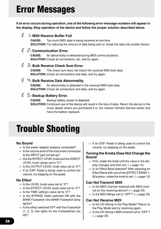
Error MessagesIf an error occurs during operation, one of the following error message numbers will appear inthe display. Stop operation of the device and follow the proper solution described below.
E 1: MIDI Receive Buffer FullCAUSE: Too much MIDI data is being received at one time.SOLUTION: Try reducing the amount of data being sent or, break the data into smaller blocks.
E 2: Communication Error.CAUSE: An abnormality is detected during MIDI communications.SOLUTION: Check all connections, etc. and try again.
E 3: Bulk Receive Check Sum Error.CAUSE: The check sum does not match the received MIDI bulk data.SOLUTION: Check all connections and data, and try again.
E 4: Bulk Receive Data Abnormality.CAUSE: An abnormality is detected in the received MIDI bulk data.SOLUTION: Check all connections and data, and try again.
E 5: Backup Battery Error.CAUSE: Backup battery power is depleted.SOLUTION: Continued use of the device will result in the loss of data. Return the device to the
music dealer where you purchased it or, the nearest Yamaha Service center andhave the battery replaced.
No Sound→ Is the power adaptor properly connected?→ Is the volume level of the instrument connected
to the INPUT jack turned up?→ Are the EFFECT LEVEL knob and the DIRECT
LEVEL knob values set to “0”?→ Is the OUTPUT LEVEL knob value set to “0”?→ If an EXP. Pedal is being used to control the
volume, try stepping on the pedal.
No Effect→ Is the LEVEL knob value set to “0”?→ Is the EFFECT LEVEL knob value set to “0”?→ Is the TIME setting’s value set to “0”?→ Is the BYPASS mode switched ON with the
BANK Footswitch (the BANK Footswitch lamplights)?
→ Is the effect switched OFF with the Footswitch(1, 2, 3) (the lights for the Footswitches areoff)?
Trouble Shooting→ If an EXP. Pedal is being used to control the
volume, try stepping on the pedal.
Turning the Knobs Does Not Change theSound
→ First, rotate the knob until the value in the dis-play changes and then set. (→ page 13)
→ Is an Effect Band selected? After selecting anEffect Band with one of the [EFFECT BAND 1-8] buttons, rotate the knob to set. (→ page 13)
Can Not Transmit MIDI→ Is the MIDI channel matched with MIDI chan-
nel on the receiving device? (→ page 25)→ Is the MIDI Merge set to “OFF”? (→ page 25)
Can Not Receive MIDI→ Is the UD-Stomp in the Play Mode? Return to
the Play Mode and try receiving again.→ Is the UD-Stomp’s MIDI channel set to “OFF”?
(→ page 25)
29
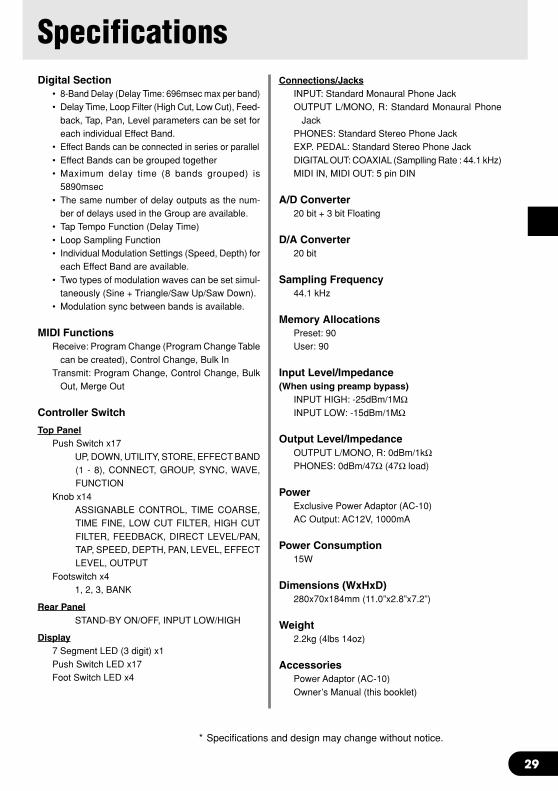
SpecificationsDigital Section
• 8-Band Delay (Delay Time: 696msec max per band)• Delay Time, Loop Filter (High Cut, Low Cut), Feed-
back, Tap, Pan, Level parameters can be set foreach individual Effect Band.
• Effect Bands can be connected in series or parallel• Effect Bands can be grouped together• Maximum delay time (8 bands grouped) is
5890msec• The same number of delay outputs as the num-
ber of delays used in the Group are available.• Tap Tempo Function (Delay Time)• Loop Sampling Function• Individual Modulation Settings (Speed, Depth) for
each Effect Band are available.• Two types of modulation waves can be set simul-
taneously (Sine + Triangle/Saw Up/Saw Down).• Modulation sync between bands is available.
MIDI FunctionsReceive: Program Change (Program Change Table
can be created), Control Change, Bulk InTransmit: Program Change, Control Change, Bulk
Out, Merge Out
Controller Switch
Top PanelPush Switch x17
UP, DOWN, UTILITY, STORE, EFFECT BAND(1 - 8), CONNECT, GROUP, SYNC, WAVE,FUNCTION
Knob x14ASSIGNABLE CONTROL, TIME COARSE,TIME FINE, LOW CUT FILTER, HIGH CUTFILTER, FEEDBACK, DIRECT LEVEL/PAN,TAP, SPEED, DEPTH, PAN, LEVEL, EFFECTLEVEL, OUTPUT
Footswitch x41, 2, 3, BANK
Rear PanelSTAND-BY ON/OFF, INPUT LOW/HIGH
Display7 Segment LED (3 digit) x1Push Switch LED x17Foot Switch LED x4
Connections/JacksINPUT: Standard Monaural Phone JackOUTPUT L/MONO, R: Standard Monaural Phone
JackPHONES: Standard Stereo Phone JackEXP. PEDAL: Standard Stereo Phone JackDIGITAL OUT: COAXIAL (Samplling Rate : 44.1 kHz)MIDI IN, MIDI OUT: 5 pin DIN
A/D Converter20 bit + 3 bit Floating
D/A Converter20 bit
Sampling Frequency44.1 kHz
Memory AllocationsPreset: 90User: 90
Input Level/Impedance(When using preamp bypass)
INPUT HIGH: -25dBm/1MΩINPUT LOW: -15dBm/1MΩ
Output Level/ImpedanceOUTPUT L/MONO, R: 0dBm/1kΩPHONES: 0dBm/47Ω (47Ω load)
PowerExclusive Power Adaptor (AC-10)AC Output: AC12V, 1000mA
Power Consumption15W
Dimensions (WxHxD)280x70x184mm (11.0”x2.8”x7.2”)
Weight2.2kg (4lbs 14oz)
AccessoriesPower Adaptor (AC-10)Owner’s Manual (this booklet)
* Specifications and design may change without notice.

30
MIDI Implementation Chart YAMAHA [ Modulation Delay] Date:14-Dec-2001
Model UD stomp MIDI Implementation Chart Version : 1.0
+----------------------------------------------------------------------+
: : Transmitted : Recognized : Remarks :
: Function ... : : : :
:-------------------+----------------+----------------+----------------:
:Basic Default : 1 - 16 : 1 - 16, off : memorized :
:Channel Changed : 1 - 16 : 1 - 16, off : :
:-------------------+----------------+----------------+----------------:
: Default : 1,3 : 1,3 : memorized :
:Mode Messages : x : x : :
: Altered : ************** : x : :
:-------------------+----------------+----------------+----------------:
:Note : x : x : :
:Number : True voice: ************** : x : :
:-------------------+----------------+----------------+----------------:
:Velocity Note ON : x : x : :
: Note OFF : x : x : :
:-------------------+----------------+----------------+----------------:
:After Key's : x : x : :
:Touch Ch's : x : x : :
:-------------------+----------------+----------------+----------------:
:Pitch Bender : x : x : :
:-------------------+----------------+----------------+----------------:
: 0 : x : x : :
: 1 - 31 : o : o : :
: 32 - 63 : x : x : :
: 64 - 95 : o : o : :
: Control 95 -127 : x : x : :
: : : : :
: Change : : : :
: : : : :

31
MIDI Implementation Chart
: : : : :
: : : : :
: : : : :
: : : : :
: : : : :
:-------------------+----------------+----------------+----------------:
:Prog : o 0 - 127 : o 0 - 127 : :
:Change : True # : ************** : : :
:-------------------+----------------+----------------+----------------:
:System Exclusive : o : o : Bulk Dump :
:-------------------+----------------+----------------+----------------:
:System : Song Pos. : x : x : :
: : Song Sel. : x : x : :
:common : Tune : x : x : :
:-------------------+----------------+----------------+----------------:
:System :Clock : x : x : :
:Real Time :Commands: x : x : :
:-------------------+----------------+----------------+----------------:
:Aux :All Sound OFF: x : x : :
: :Re
set
All
Cntr
ls : x : x : :
: :Local ON/OFF : x : x : :
: :All Notes OFF: x : x : :
:Mes- :Active Sense : o : x : :
:sages:Reset : x : x : :
:-------------------+----------------+----------------+----------------:
: :
: :
+-------------------+----------------+----------------+----------------+
Mode 1 : OMNI ON, POLY Mode 2 : OMNI ON, MONO o : Yes
Mode 3 : OMNI OFF, POLY Mode 4 : OMNI OFF, MONO x : No

Printed in TaiwanV839860