Embed Size (px)
DESCRIPTION
ppt. of fits and tolerences
Citation preview

www.Ramakantrana.com
www.Ramakantrana.com
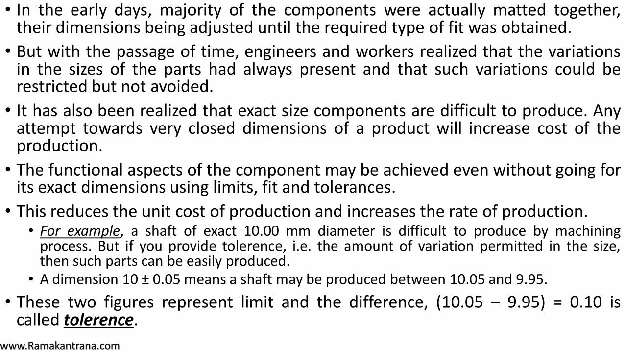
• In the early days, majority of the components were actually matted together,their dimensions being adjusted until the required type of fit was obtained.
• But with the passage of time, engineers and workers realized that the variationsin the sizes of the parts had always present and that such variations could berestricted but not avoided.
• It has also been realized that exact size components are difficult to produce. Anyattempt towards very closed dimensions of a product will increase cost of theproduction.
• The functional aspects of the component may be achieved even without going forits exact dimensions using limits, fit and tolerances.
• This reduces the unit cost of production and increases the rate of production.• For example, a shaft of exact 10.00 mm diameter is difficult to produce by machining
process. But if you provide tolerence, i.e. the amount of variation permitted in the size,then such parts can be easily produced.
• A dimension 10 ± 0.05 means a shaft may be produced between 10.05 and 9.95.
• These two figures represent limit and the difference, (10.05 – 9.95) = 0.10 iscalled tolerence.
www.Ramakantrana.com
• When two parts are to be assembled, the relation resulting from the differencebetween their sizes before assembly is called a fit.
• A fit may be defined as the degree of tightness and looseness between twomating parts.
FITS AND THEIR CLASSIFICATIONS
www.Ramakantrana.com
The important terms related to the fit are given below :
www.Ramakantrana.com
• In a fit, this is the difference between the sizes of the hole and theshaft, before assembly, when this difference is positive.
• The clearance may be maximum clearance and minimum clearance.
• Minimum clearance in the fit is the difference between the maximumsize of the hole and the minimum size of the shaft.
Clearance
www.Ramakantrana.com
• It is the difference between the sizes of the hole and the shaft beforeassembly, when the difference is negative.
• The interference may be maximum or minimum.
• Maximum interference is arithmetical difference between theminimum size of the hole and the maximum size of the shaft beforeassembly.
• Minimum interference is the difference between the maximum size ofthe hole and the minimum size of the shaft.
Interference
www.Ramakantrana.com
• It is between clearance and interference, where the tolerance zones ofthe holes and shaft overlap.
Transition
www.Ramakantrana.com
(i) Clearance Fit.
(ii) Interference Fit.
(iii) Transition Fit.
So, you can see that fits depend upon the actual limits of the hole and or shaft and can be divided
into three general classes :
www.Ramakantrana.com
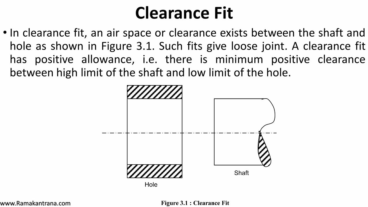
• In clearance fit, an air space or clearance exists between the shaft andhole as shown in Figure 3.1. Such fits give loose joint. A clearance fithas positive allowance, i.e. there is minimum positive clearancebetween high limit of the shaft and low limit of the hole.
Clearance Fit
www.Ramakantrana.com
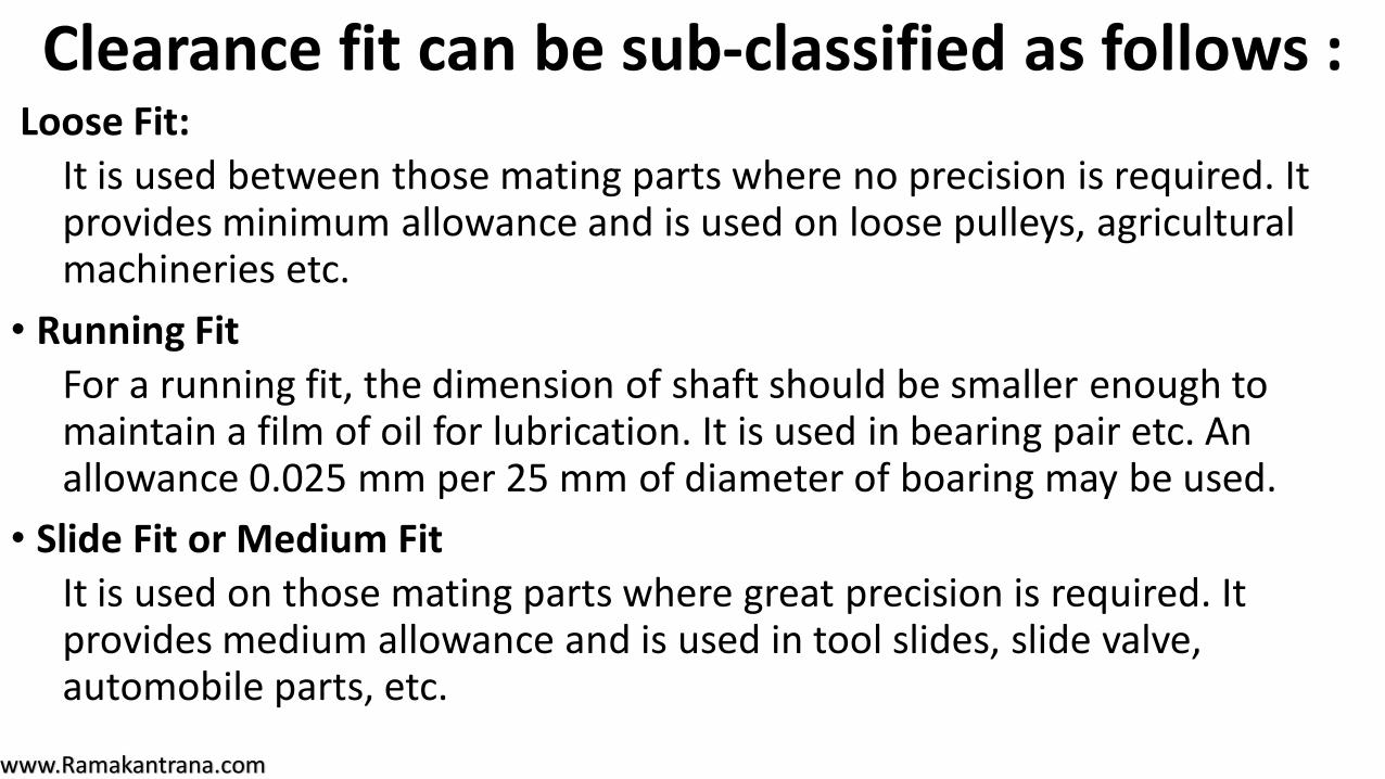
Loose Fit:
It is used between those mating parts where no precision is required. It provides minimum allowance and is used on loose pulleys, agricultural machineries etc.
• Running Fit
For a running fit, the dimension of shaft should be smaller enough to maintain a film of oil for lubrication. It is used in bearing pair etc. An allowance 0.025 mm per 25 mm of diameter of boaring may be used.
• Slide Fit or Medium Fit
It is used on those mating parts where great precision is required. It provides medium allowance and is used in tool slides, slide valve, automobile parts, etc.
Clearance fit can be sub-classified as follows :
www.Ramakantrana.com
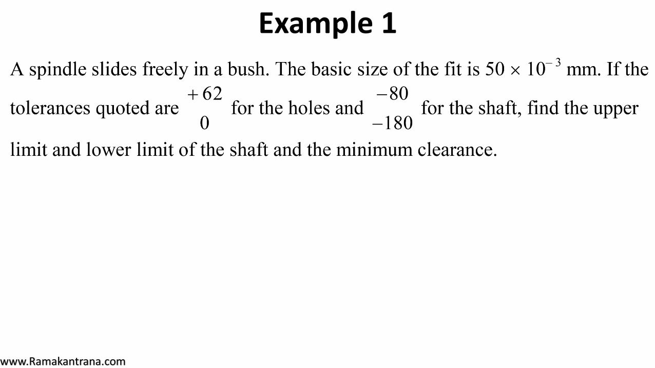
Example 1
www.Ramakantrana.com
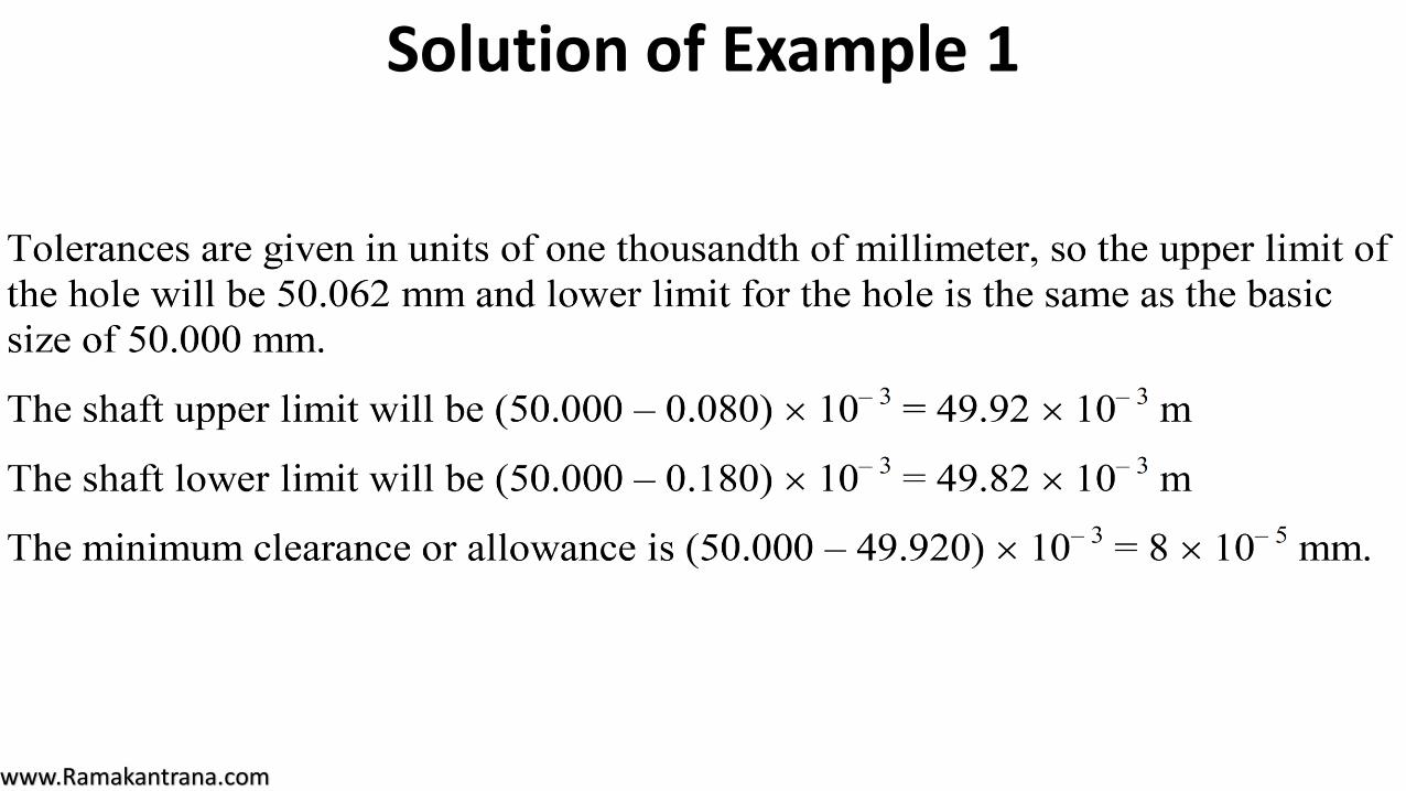
Solution of Example 1
www.Ramakantrana.com
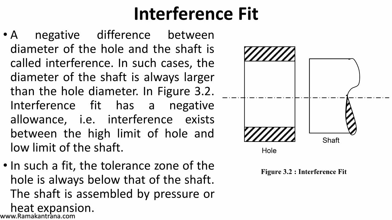
• A negative difference betweendiameter of the hole and the shaft iscalled interference. In such cases, thediameter of the shaft is always largerthan the hole diameter. In Figure 3.2.Interference fit has a negativeallowance, i.e. interference existsbetween the high limit of hole andlow limit of the shaft.
• In such a fit, the tolerance zone of thehole is always below that of the shaft.The shaft is assembled by pressure orheat expansion.
Interference Fit
www.Ramakantrana.com
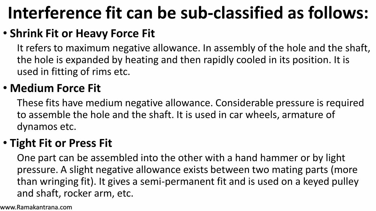
• Shrink Fit or Heavy Force Fit It refers to maximum negative allowance. In assembly of the hole and the shaft, the hole is expanded by heating and then rapidly cooled in its position. It is used in fitting of rims etc.
• Medium Force Fit These fits have medium negative allowance. Considerable pressure is required to assemble the hole and the shaft. It is used in car wheels, armature of dynamos etc.
• Tight Fit or Press Fit One part can be assembled into the other with a hand hammer or by light pressure. A slight negative allowance exists between two mating parts (more than wringing fit). It gives a semi-permanent fit and is used on a keyed pulley and shaft, rocker arm, etc.
Interference fit can be sub-classified as follows:
www.Ramakantrana.com
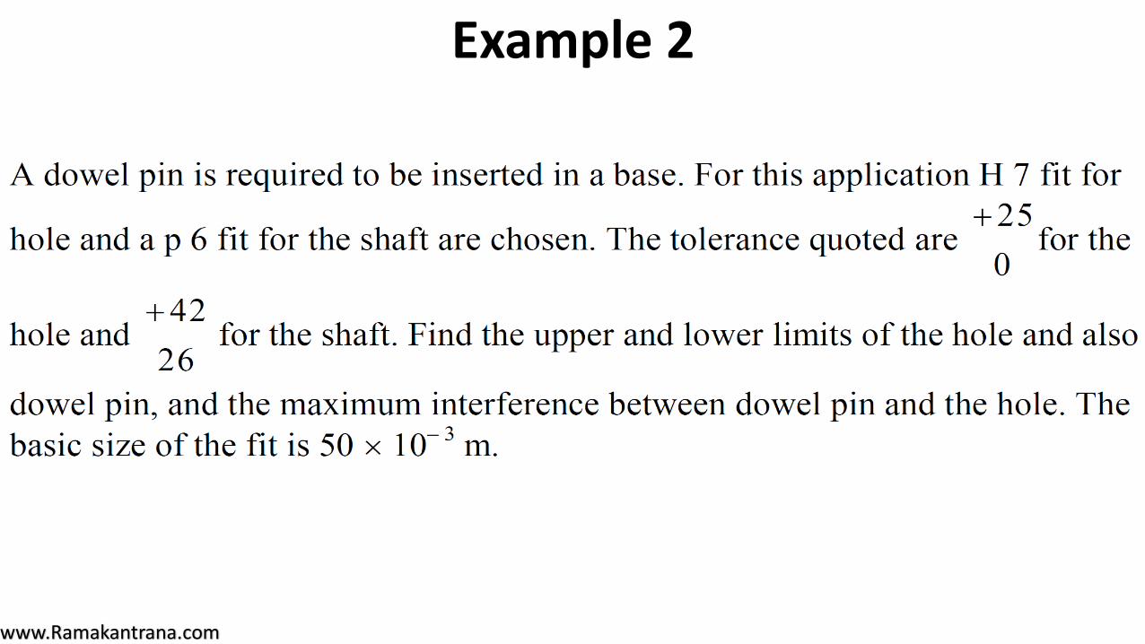
Example 2
www.Ramakantrana.com
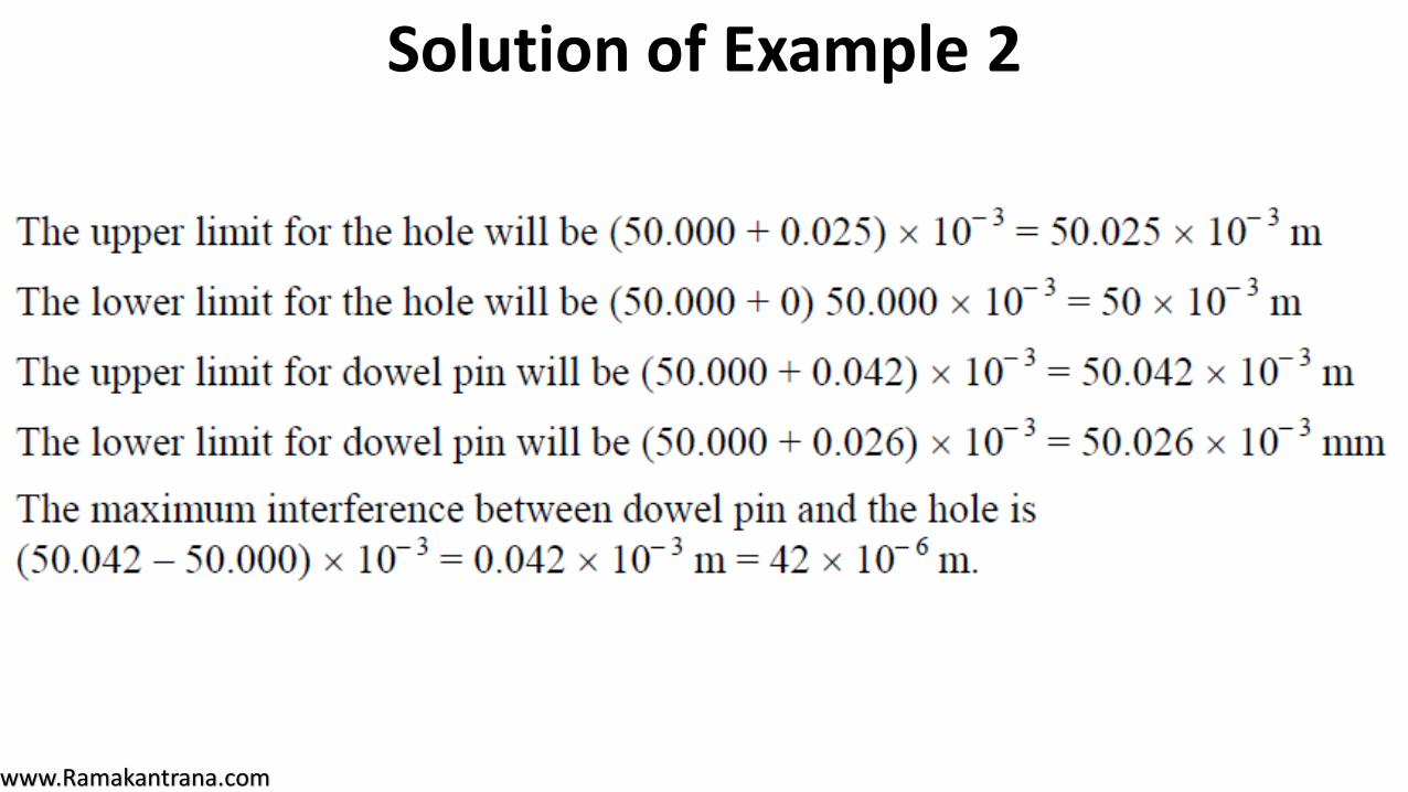
Solution of Example 2
www.Ramakantrana.com
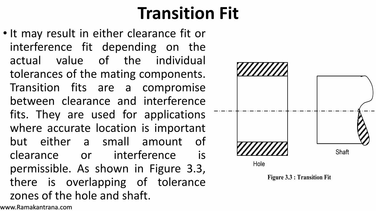
• It may result in either clearance fit orinterference fit depending on theactual value of the individualtolerances of the mating components.Transition fits are a compromisebetween clearance and interferencefits. They are used for applicationswhere accurate location is importantbut either a small amount ofclearance or interference ispermissible. As shown in Figure 3.3,there is overlapping of tolerancezones of the hole and shaft.
Transition Fit
www.Ramakantrana.com
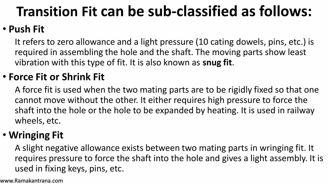
• Push Fit It refers to zero allowance and a light pressure (10 cating dowels, pins, etc.) is required in assembling the hole and the shaft. The moving parts show least vibration with this type of fit. It is also known as snug fit.
• Force Fit or Shrink Fit A force fit is used when the two mating parts are to be rigidly fixed so that one cannot move without the other. It either requires high pressure to force the shaft into the hole or the hole to be expanded by heating. It is used in railway wheels, etc.
• Wringing Fit A slight negative allowance exists between two mating parts in wringing fit. It requires pressure to force the shaft into the hole and gives a light assembly. It is used in fixing keys, pins, etc.
Transition Fit can be sub-classified as follows:

www.Ramakantrana.com
Example 3
www.Ramakantrana.com
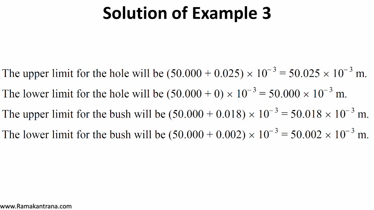
Solution of Example 3
www.Ramakantrana.com
SYSTEMS OF FIT • A fit system is the systems of standard allowance to suit specific range
of basic size. If these standard allowances are selected properly and assigned in mating parts ensures specific classes of fit.
• There are two systems of fit for obtaining clearance, interference or transition fit.
• These are :
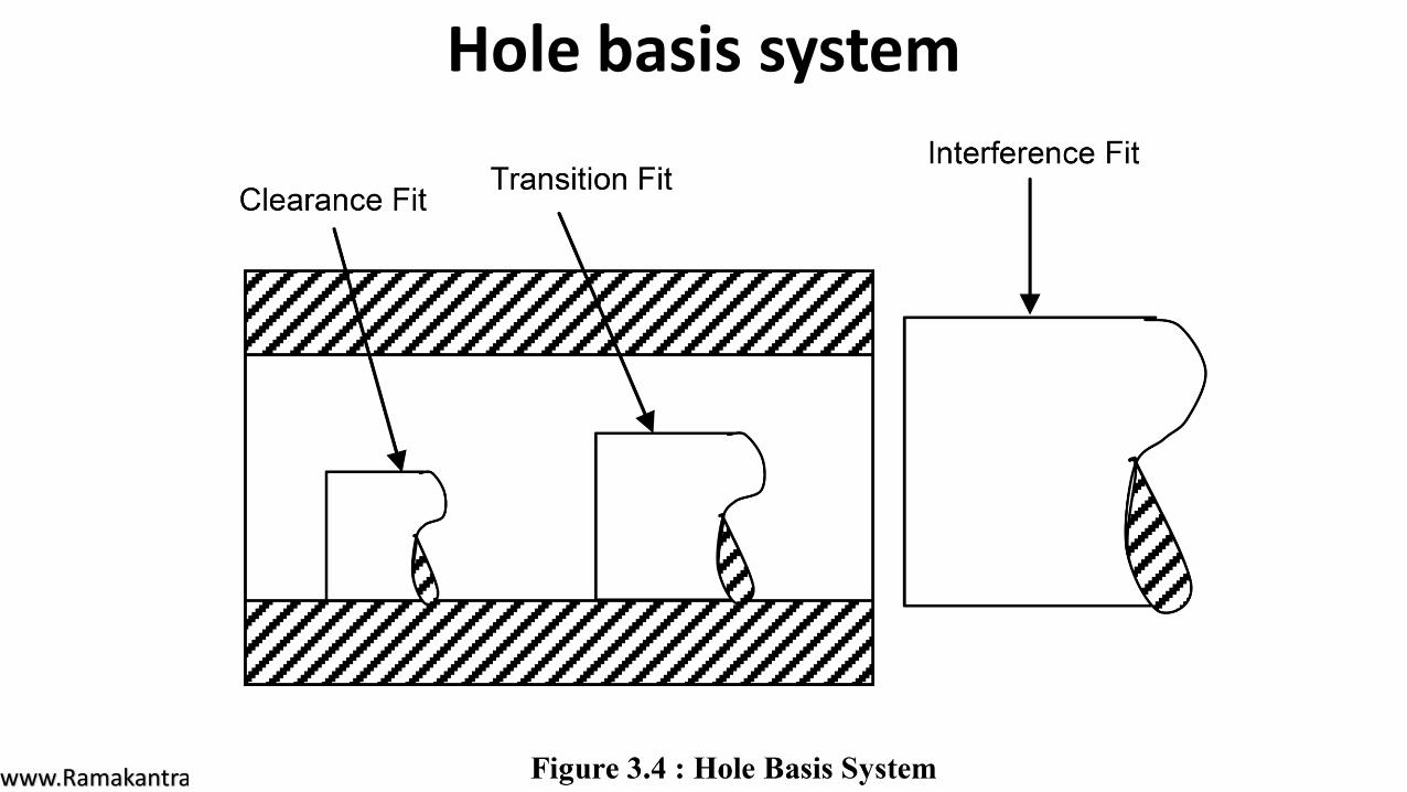
(i) Hole basis system (Figure 3.4)
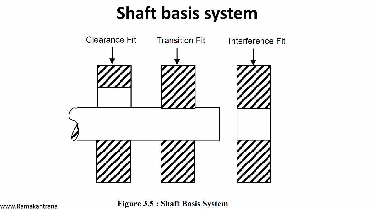
(ii) Shaft basis system (Figure 3.5)
www.Ramakantrana.com
Hole basis system
www.Ramakantrana.com
Hole basis system
• In the hole basis system, the size of the hole is kept constant and shaft sizes arevaried to obtain various types of fits.
• In this system, lower deviation of hole is zero, i.e. the low limit of hole is same asbasic size. The high limit of the hole and the two limits of size for the shaft arethen varied to give desired type of fit.
• The hole basis system is commonly used because it is more convenient to makecorrect holes of fixed sizes, since the standard drills, taps, reamers and branchesetc. are available for producing holes and their sizes are not adjustable.
• On the other hand, size of the shaft produced by turning, grinding, etc. can bevery easily varied.
www.Ramakantrana.com
Shaft basis system
www.Ramakantrana.com
Shaft basis system• In the shaft basis system, the size of the shaft is kept constant and different fits
are obtained by varying the size of the hole.
• Shaft basis system is used when the ground bars or drawn bars are readilyavailable.
• These bars do not require further machining and fits are obtained by varying thesizes of the hole.
• In this system, the upper deviation (fundamental deviation) of shaft is zero, i.e.the high limit of the shaft is same as basic size and the various fits are obtainedby varying the low limit of shaft and both the limits of the hole.
www.Ramakantrana.com
TOLERANCE AND ITS CLASSIFICATION • The permissible variation in size or dimension is tolerance.
• Thus, the word tolerance indicates that a worker is not expected to produce thepart of the exact size, but definite a small size error is permitted.
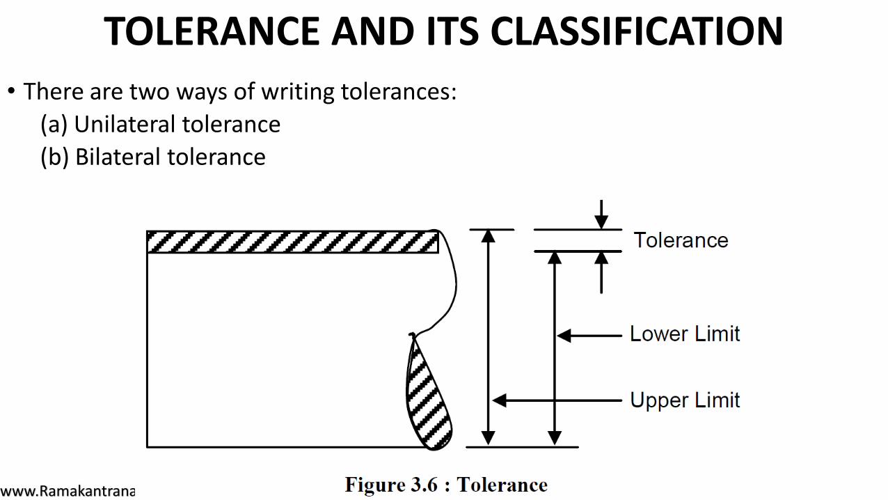
• The difference between the upper limit (high limit) and the lower limit of adimension represents the margin for variation to workmanship, and is called atolerance zone (Figure 3.6).
• Tolerance can also be defined as the amount by which the job is allowed to goaway from accuracy and perfectness without causing any functional trouble,when assembled with its mating part and put into actual service.
www.Ramakantrana.com
TOLERANCE AND ITS CLASSIFICATION • There are two ways of writing tolerances:
(a) Unilateral tolerance
(b) Bilateral tolerance
www.Ramakantrana.com
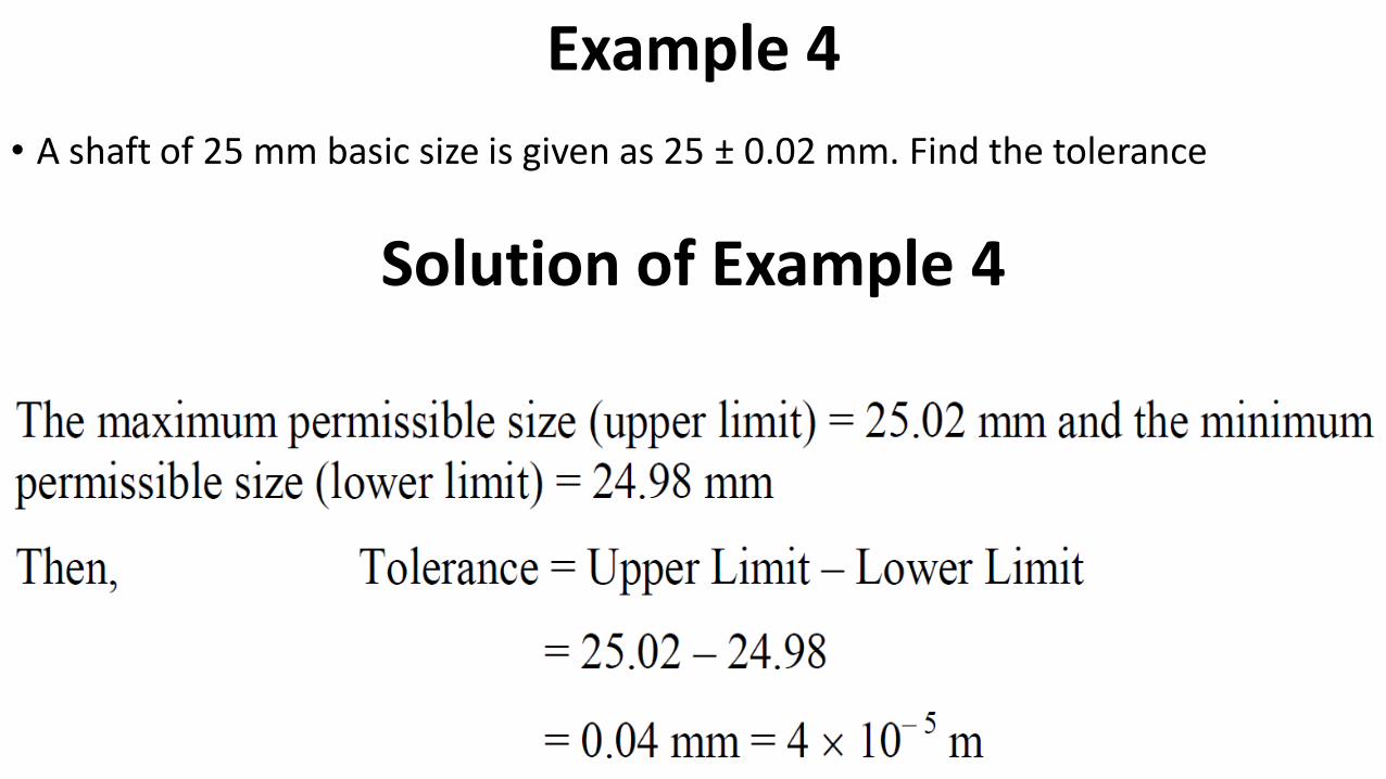
Example 4
• A shaft of 25 mm basic size is given as 25 ± 0.02 mm. Find the tolerance
Solution of Example 4
www.Ramakantrana.com
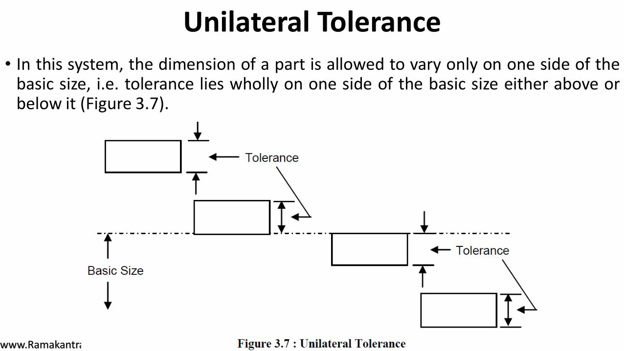
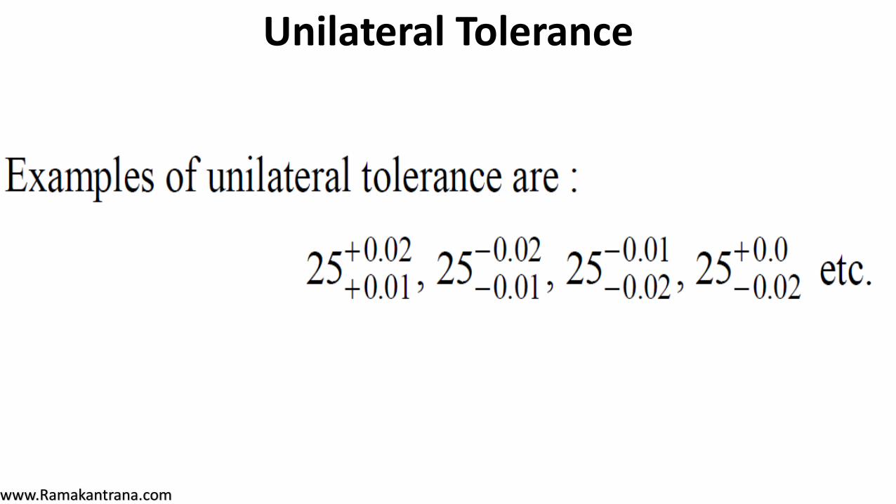
Unilateral Tolerance • In this system, the dimension of a part is allowed to vary only on one side of the
basic size, i.e. tolerance lies wholly on one side of the basic size either above orbelow it (Figure 3.7).
www.Ramakantrana.com
Unilateral Tolerance
www.Ramakantrana.com
Unilateral Tolerance
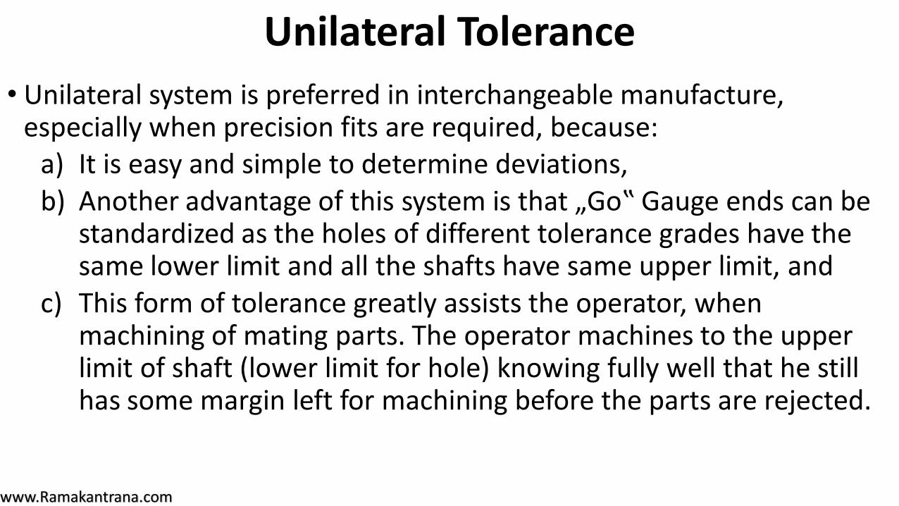
• Unilateral system is preferred in interchangeable manufacture, especially when precision fits are required, because:
a) It is easy and simple to determine deviations, b) Another advantage of this system is that „Go‟ Gauge ends can be
standardized as the holes of different tolerance grades have the same lower limit and all the shafts have same upper limit, and
c) This form of tolerance greatly assists the operator, when machining of mating parts. The operator machines to the upper limit of shaft (lower limit for hole) knowing fully well that he still has some margin left for machining before the parts are rejected.
www.Ramakantrana.com
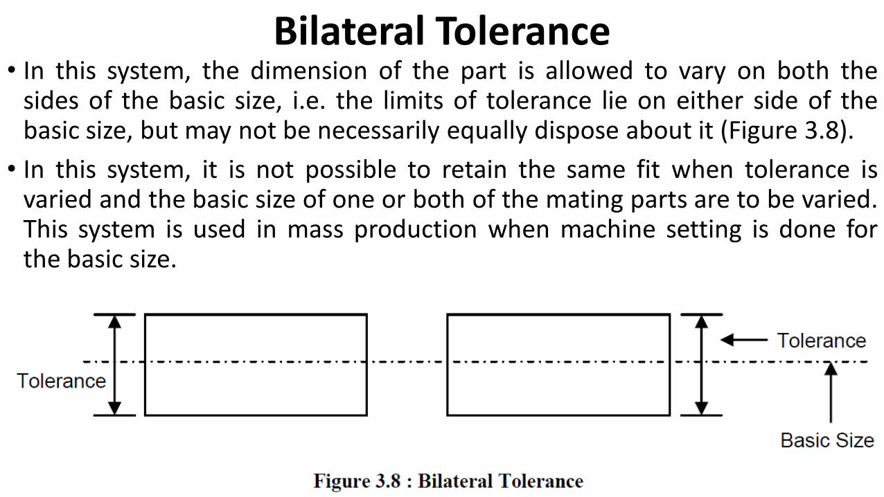
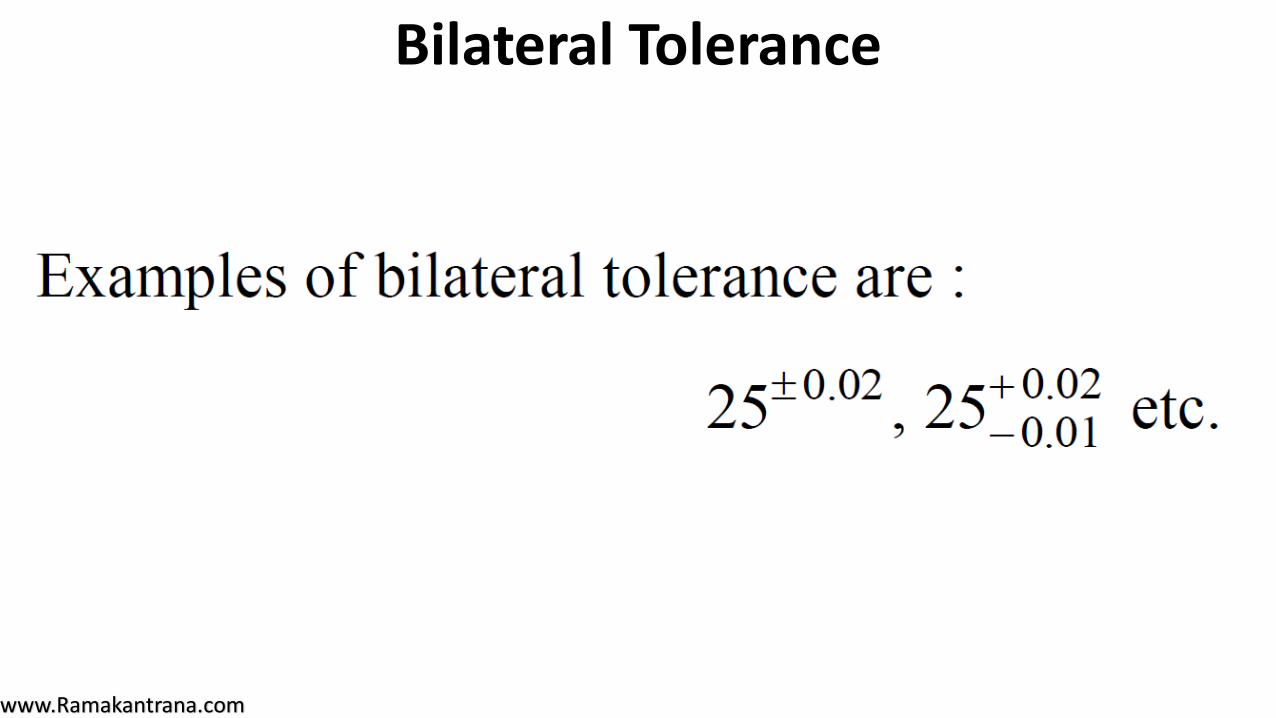
Bilateral Tolerance • In this system, the dimension of the part is allowed to vary on both the
sides of the basic size, i.e. the limits of tolerance lie on either side of thebasic size, but may not be necessarily equally dispose about it (Figure 3.8).
• In this system, it is not possible to retain the same fit when tolerance isvaried and the basic size of one or both of the mating parts are to be varied.This system is used in mass production when machine setting is done forthe basic size.
www.Ramakantrana.com
Bilateral Tolerance
www.Ramakantrana.com
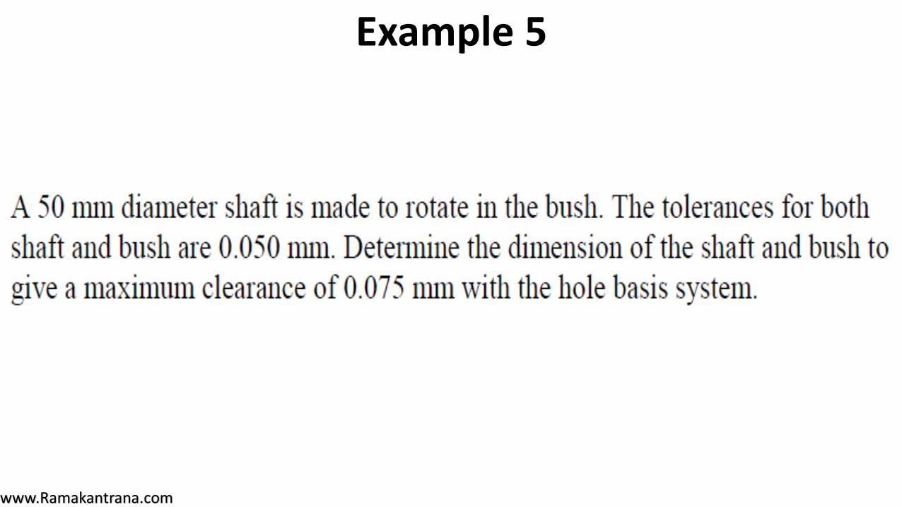
Example 5
www.Ramakantrana.com
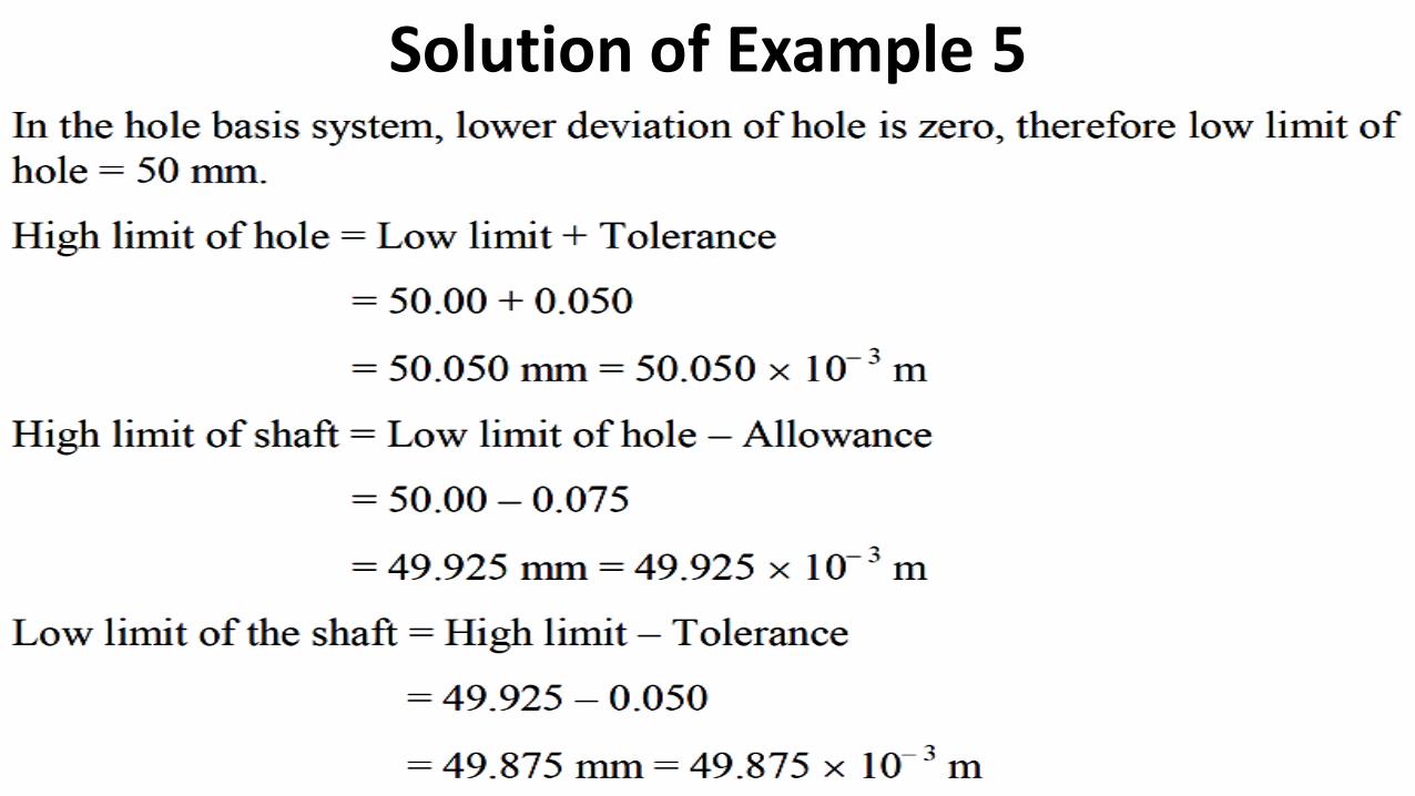
Solution of Example 5
www.Ramakantrana.com
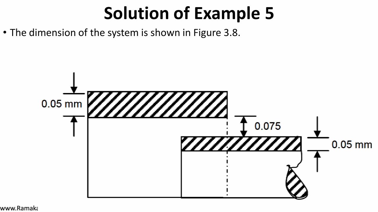
Solution of Example 5• The dimension of the system is shown in Figure 3.8.
www.Ramakantrana.com
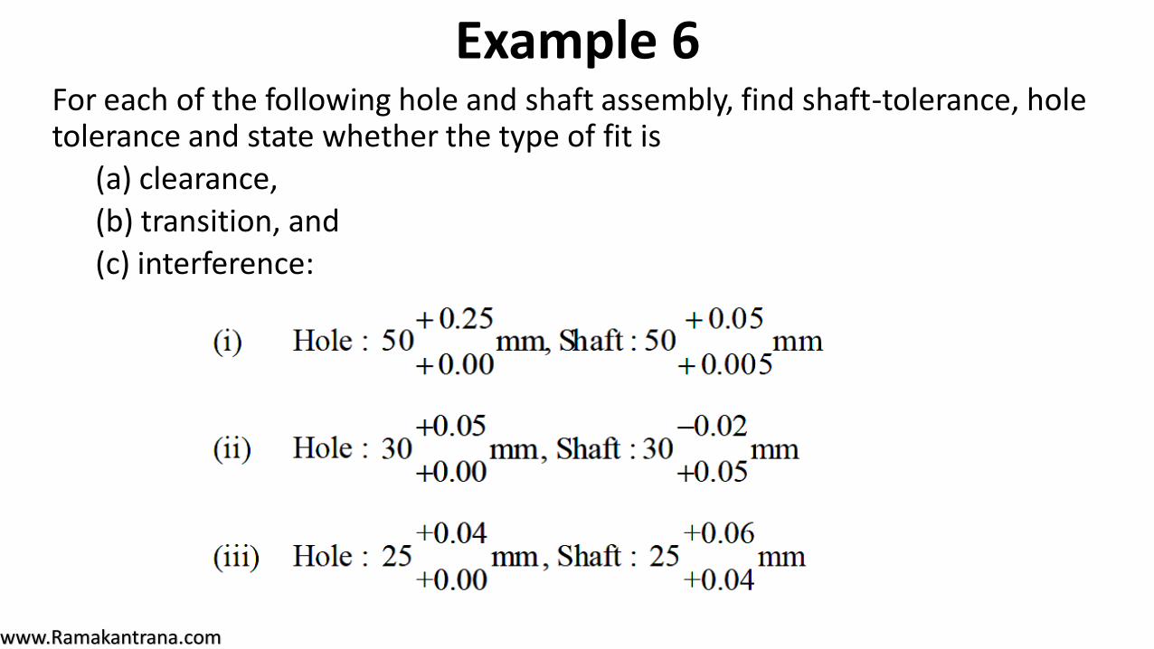
Example 6For each of the following hole and shaft assembly, find shaft-tolerance, hole tolerance and state whether the type of fit is
(a) clearance,
(b) transition, and
(c) interference:
www.Ramakantrana.com
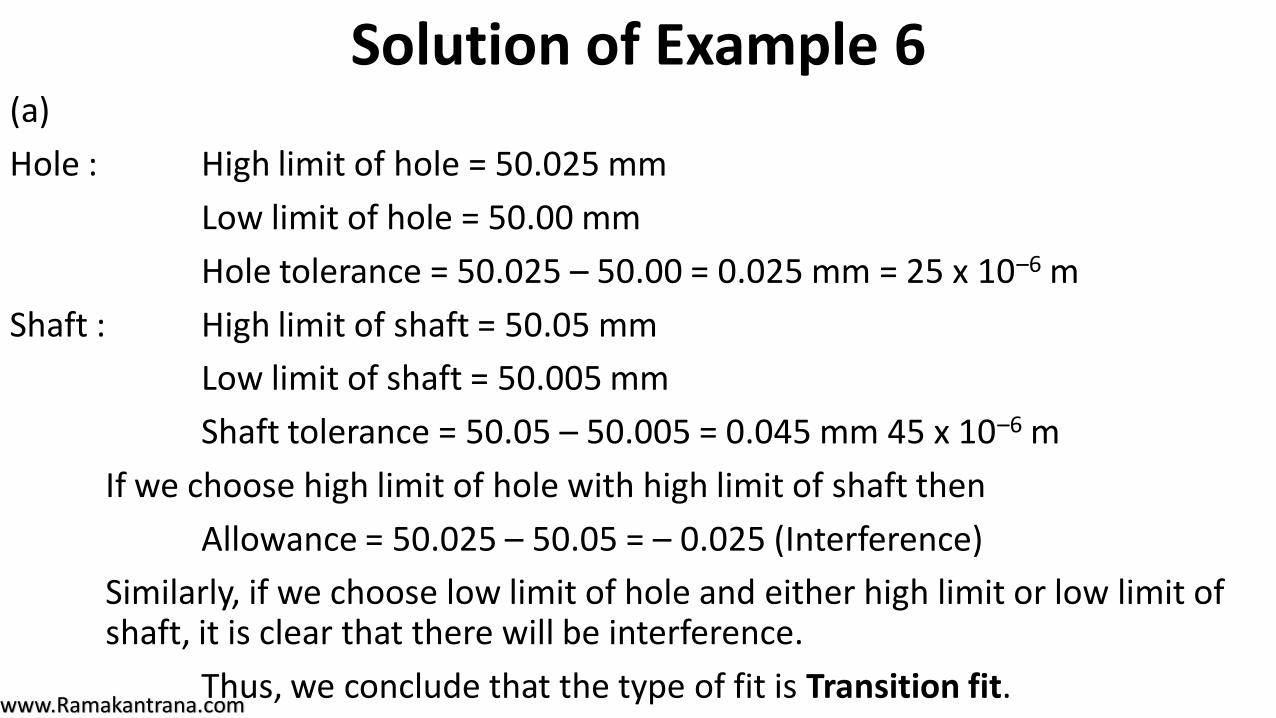
Solution of Example 6(a)
Hole : High limit of hole = 50.025 mm
Low limit of hole = 50.00 mm
Hole tolerance = 50.025 – 50.00 = 0.025 mm = 25 x 10–6 m
Shaft : High limit of shaft = 50.05 mm
Low limit of shaft = 50.005 mm
Shaft tolerance = 50.05 – 50.005 = 0.045 mm 45 x 10–6 m
If we choose high limit of hole with high limit of shaft then
Allowance = 50.025 – 50.05 = – 0.025 (Interference)
Similarly, if we choose low limit of hole and either high limit or low limit of shaft, it is clear that there will be interference.
Thus, we conclude that the type of fit is Transition fit.
www.Ramakantrana.com
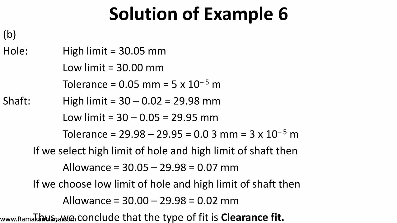
Solution of Example 6(b)
Hole: High limit = 30.05 mm
Low limit = 30.00 mm
Tolerance = 0.05 mm = 5 x 10– 5 m
Shaft: High limit = 30 – 0.02 = 29.98 mm
Low limit = 30 – 0.05 = 29.95 mm
Tolerance = 29.98 – 29.95 = 0.0 3 mm = 3 x 10– 5 m
If we select high limit of hole and high limit of shaft then
Allowance = 30.05 – 29.98 = 0.07 mm
If we choose low limit of hole and high limit of shaft then
Allowance = 30.00 – 29.98 = 0.02 mm
Thus, we conclude that the type of fit is Clearance fit.
www.Ramakantrana.com
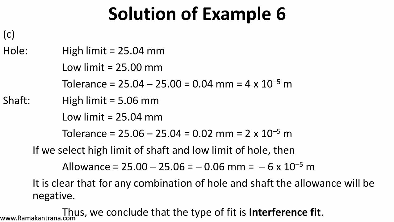
Solution of Example 6(c)
Hole: High limit = 25.04 mm
Low limit = 25.00 mm
Tolerance = 25.04 – 25.00 = 0.04 mm = 4 x 10⁻⁵ m
Shaft: High limit = 5.06 mm
Low limit = 25.04 mm
Tolerance = 25.06 – 25.04 = 0.02 mm = 2 x 10⁻⁵ m
If we select high limit of shaft and low limit of hole, then
Allowance = 25.00 – 25.06 = – 0.06 mm = – 6 x 10⁻⁵ m
It is clear that for any combination of hole and shaft the allowance will be negative.
Thus, we conclude that the type of fit is Interference fit.
www.Ramakantrana.com
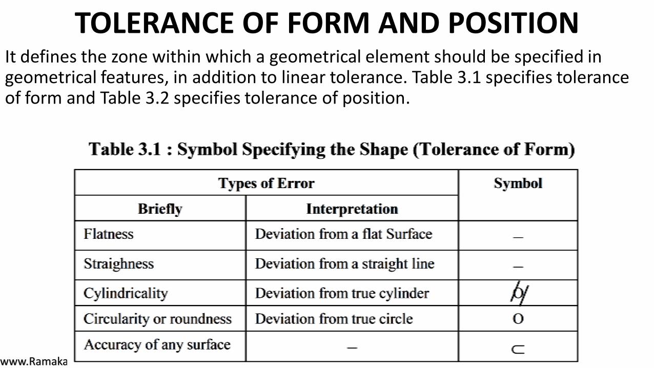
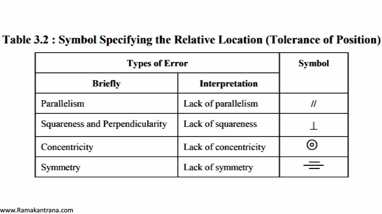
TOLERANCE OF FORM AND POSITION It defines the zone within which a geometrical element should be specified in geometrical features, in addition to linear tolerance. Table 3.1 specifies tolerance of form and Table 3.2 specifies tolerance of position.
www.Ramakantrana.com
www.Ramakantrana.com
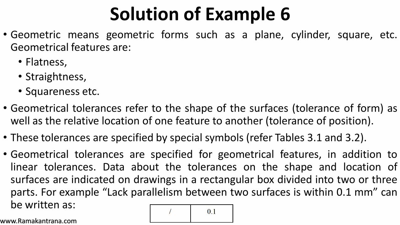
Solution of Example 6• Geometric means geometric forms such as a plane, cylinder, square, etc.
Geometrical features are:
• Flatness,
• Straightness,
• Squareness etc.
• Geometrical tolerances refer to the shape of the surfaces (tolerance of form) aswell as the relative location of one feature to another (tolerance of position).
• These tolerances are specified by special symbols (refer Tables 3.1 and 3.2).
• Geometrical tolerances are specified for geometrical features, in addition tolinear tolerances. Data about the tolerances on the shape and location ofsurfaces are indicated on drawings in a rectangular box divided into two or threeparts. For example “Lack parallelism between two surfaces is within 0.1 mm” canbe written as:
www.Ramakantrana.com
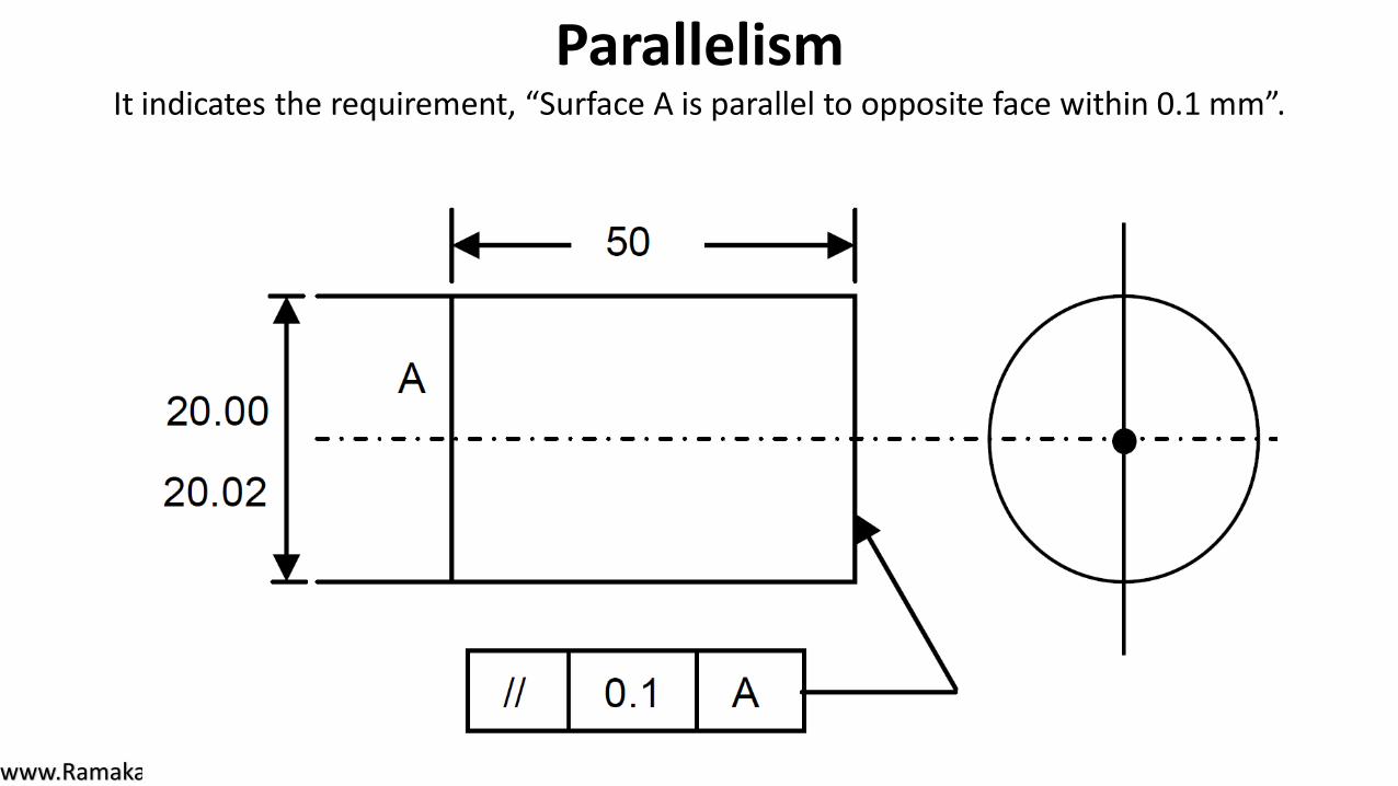
ParallelismIt indicates the requirement, “Surface A is parallel to opposite face within 0.1 mm”.
www.Ramakantrana.com
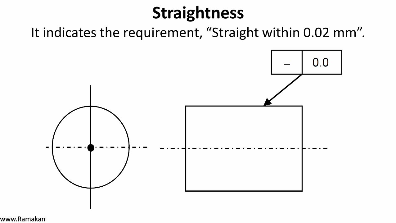
StraightnessIt indicates the requirement, “Straight within 0.02 mm”.

www.Ramakantrana.com
SquarenessIt indicates the requirement, “Square within 0.03 mm total”.
www.Ramakantrana.com
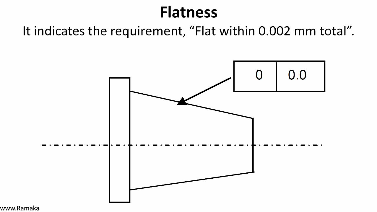
FlatnessIt indicates the requirement, “Flat within 0.002 mm total”.
www.Ramakantrana.com
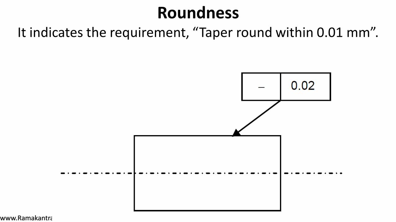
Roundness It indicates the requirement, “Taper round within 0.01 mm”.