Embed Size (px)
Citation preview

737
2013,25(5):737-746 DOI: 10.1016/S1001-6058(13)60420-5
Flow characteristics of the two tandem wavy cylinders and drag reduction phe- nomenon*
ZOU Lin (邹琳), GUO Congbo (郭丛波), XIONG Can (熊灿) School of Mechanical and Electronic Engineering, Wuhan University of Technology, Wuhan 430070, China, E-mail: [email protected] (Received February 27, 2013, Revised July 3, 2013) Abstract: This paper presents an extensive numerical study of 3-D laminar flow around two wavy cylinders in the tandem arrangement for spacing ratios ( / )mL D ranging from 1.5 to 5.5 at a low Reynolds number of 100. The investigation focuses on the
effects of spacing ratio ( / )mL D and wavy surface on the 3-D near wake flow patterns, the force and pressure coefficients and the
vortex shedding frequency for the two tandem wavy cylinders. Flows around the two tandem circular cylinders are also obtained for comparison. With the spacing ratio in the range of / = 1.5 - 5.5mL D , unlike two tandem circular cylinders, the wavy cylinders in the
tandem arrangement do not have the wake interference behaviour of three basic types. The vortex shedding behind the upstream wavy cylinder occurs at a further downstream position as compared with that of the upstream circular cylinder. This leads to the weakening of the effect of the vibration of the cylinders as well as a distinct drag reduction. The effects of the drag reduction and the control of the vibration of the two wavy cylinders in tandem become more and more evident when / mL D 4.0, with a distinct
vortex shedding in the upstream cylinder regime for the two circular cylinders in tandem. Key words: wavy cylinders, tandem arrangement, spacing ratio, drag reduction, vibration
Introduction Flows past multiple cylindrical bodies are impo-
rtant in many engineering applications, for example, in the designs of cables, offshore structures, heat ex- changers, high-rise buildings, and chimneys. The periodic vortex shedding and the fluctuating velocity fields behind the cylindrical bodies can cause structu- ral damages, shorten the life of the structures and even lead to severe accidents. Hence, it is necessary to study the complicated flow around such multiple cyli- nders in order to improve the design of such equip- ment. The flow past cylindrical bodies, especially, that around one or two cylinders, has been extensively in- vestigated. Williamson[1] and Wang[2] investigated the vortex dynamics of the wake behind a cylinder. For
* Project supported by the National Natural Science Foun- dation of China (Grant No. 11172220). Biography: ZOU Lin (1970-), Female, Ph. D., Associate Professor
two circular cylinders in tandem arrangements, Lin et al.[3] and Deng et al.[4] investigated the near wake flow past two tandem circular cylinders and Jiang and Lin[5] studied the flows past two tandem cylinders of diffe- rent diameters. These studies show that the flow around two tandem circular cylinders is sensitive to both Re and the spacing ratio ( / )L D . Zdravkovich[6]
subdivided the flow patterns into three basic types based on the wake interference behaviour, Xu and Zhou[7] and Zhou and Yiu[8] also found the similar phenomenon, and a similar classification scheme was used by Carmo et al.[9,10], based on numerical simula- tions of two tandem circular cylinders. Sumner[11] re- viewed the characteristics of two circular cylinders of equal diameter in a steady cross-flow.
It is a challenge to control the vortex-shedding phenomenon and hence to reduce the potential of flow-induced vibrations for the two cylinders in tandem arrangements. In order to suppress the asso- ciated bodies’ vibration, many experimental and numerical investigations were carried out over the past years. In recent few years, several types of cylinders
738
with a surface profile in sinusoidal curve along their spanwise direction, named the wavy cylinders, were introduced. The wavy cylinders can achieve the pur- pose of drag reduction and vibration damping at the same time. Lam et al.[12-15] investigated the control of force and bodies’ vibration of a wavy cylinder. They identified the optimal value of the spanwise wave- length ( / = 6)mD for the drag force reduction and
the fluctuating lift suppression at = 100Re , and the maximum drag coefficient reduction can reach 18%, while the r.m.s. lift coefficient was equal to zero. Furthermore, they also found that a wavy cylinder with such a spanwise wavelength can provide a signi- ficant drag reduction and body vibration suppression for turbulent flows at subcritical Reynolds numbers from 6 800 to 13 400. Then they studied the three- dimensional flow characteristics of such optimal wavy cylinder with yaw angles from 0o to 60o . Lam et al.[16] investigated turbulent flows around two fixed unya- wed and yawed out-of-phase wavy cylinders in tandem arrangement at a subcritical Reynolds number of 3 900.
With regard to the investigations on the cross- flow past two-tandem-cylinder arrays, most of the pre- vious studies were focused on the effects of the spa- cing ratio on the two tandem circular cylinders. The effects of the spacing ratio of two-tandem-cylinder arrays and the wavy surfaces at the low Re have not yet been fully investigated. The understanding of the complex physical mechanism of 3-D flow characteri- stics around two wavy cylinders in the tandem confi- guration at low Re is still inadequate, as it is very di- fficult to gain this understanding by experimental measurements. The present investigation focuses on the effects of spacing ratio ( / )mL D and wavy surface
on the 3-D instantaneous near wake flow patterns, force and pressure coefficients and vortex shedding frequency for the two tandem wavy cylinders of diffe- rent spacing ratios at = 100Re . The main objectives of the present work are to discover whether this type of wavy cylinder configurations with various spacing ratios at low Re can still suppress bodies’ vibration and reduce the drag force at the same time. In this paper, some valuable data, such as the drag, lift, the pressure, the velocity flied, the vortex shedding fre- quency and the flow pattern, are discussed in detail and compared with corresponding circular cylinders at the same arrangement. The physical mechanism of the drag reduction, as well as the influence of the up- stream and downstream wavy cylinders will be stu- died. It is hoped that such an investigation will be helpful in engineering applications such as the vibra- tions of cables in suspension bridges and multiple risers in offshore engineering.
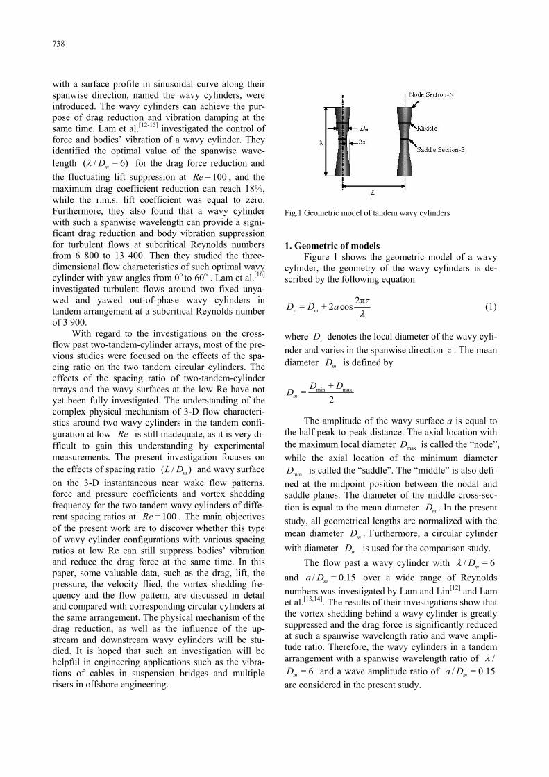
Fig.1 Geometric model of tandem wavy cylinders 1. Geometric of models
Figure 1 shows the geometric model of a wavy cylinder, the geometry of the wavy cylinders is de- scribed by the following equation
2= + 2 cosz m
zD D a
(1)
where zD denotes the local diameter of the wavy cyli-
nder and varies in the spanwise direction z . The mean diameter mD is defined by
min max+=
2m
D DD
The amplitude of the wavy surface a is equal to
the half peak-to-peak distance. The axial location with the maximum local diameter maxD is called the “node”,
while the axial location of the minimum diameter
minD is called the “saddle”. The “middle” is also defi-
ned at the midpoint position between the nodal and saddle planes. The diameter of the middle cross-sec- tion is equal to the mean diameter mD . In the present
study, all geometrical lengths are normalized with the mean diameter mD . Furthermore, a circular cylinder
with diameter mD is used for the comparison study.
The flow past a wavy cylinder with / = 6mD
and / = 0.15ma D over a wide range of Reynolds
numbers was investigated by Lam and Lin[12] and Lam et al.[13,14]. The results of their investigations show that the vortex shedding behind a wavy cylinder is greatly suppressed and the drag force is significantly reduced at such a spanwise wavelength ratio and wave ampli- tude ratio. Therefore, the wavy cylinders in a tandem arrangement with a spanwise wavelength ratio of /
= 6mD and a wave amplitude ratio of / = 0.15ma D
are considered in the present study.

739
2. Numerical method 2.1 Governing equations
In the present study, the unsteady 3-D laminar flow of a viscous incompressible fluid is considered. The Finite Volume Method (FVM) with a structured hexahedral grid is employed to solve the unsteady 3-D incompressible Navier-Stokes equations.
The 3-D dimensionless Navier-Stokes equations governing the flow of a Newtonian fluid can be wri- tten in vector form as
2
+ = +u
pt Re
u
u u , = 0 u (2)
where u is the non-dimensional flow velocity vector in the Cartesian coordinate system ( , , )x y z with its
three velocity components u , v and w . The Semi-Implicit Pressure Linked Equations
(SIMPLE) method is used to deal with the pressure velocity coupling between the momentum and the continuity equations. The second-order upwind diffe- rencing scheme is used for convective terms. The second-order central difference scheme is adopted for diffusion terms, while the second-order implicit scheme is employed to discretize the equations in time. 2.2 Computational domain and boundary conditions
In the present study, the computational domain is a cube. Similar to the study of Lam et al.[13], the height ( )H of computational domain is equal to one wave-
length ( = = 6 )mH D in the spanwise z -direction.
The upstream boundary of the computational domain is set at a distance of 12 mD from the centreline of the
upper wavy cylinder, while the downstream boundary is 20 mD away from the down wavy cylinder, and each
lateral surface is 12 mD away from the axis of the cyli-
nder. The boundary conditions are summarized as
follows. At the inlet boundary, a uniform velocity pro- file is imposed. And the Neumann-type boundary con- dition is adopted at the outlet. The lateral surfaces are treated as slip surfaces, using the symmetry boundary conditions. Furthermore, at the boundaries in the span- wise direction, a periodic boundary condition is em- ployed, and the no-slip boundary condition is prescri- bed at the surface of the wavy cylinders.
Similar grid distributions are used in the present simulations (see Fig.2), based on the previous simula- tion models on the flow past a single wavy cylinder[13]. Figure 2 shows the detailed diagram of the grid system. In the -x y plane, the unstructured hexahed-
ral grids are non-uniform with 120 grid points unifor-
mly distributed along the circumferential direction of each cylinder, while 56 uniform layers of cells are used in the spanwise direction along the z -direction.
Fig.2 Computational domain and grid distribution
Details of the grid independence tests and the va- lidation of the numerical models are listed in Table 1. Because of many available numerical simulations and experimental researches on circular cylinders, the grid independence tests on circular cylinders are made. As shown in Table 1, the difference of the results between coarse and fine grid distributions of circular cylinders is not significant. The results of wavy cyli- nders are also very good. So the coarser grid distribu- tion model is adopted in the present simulations on the flow past two cylinders to save computing time. 3. Results and discussions 3.1 Flow patterns
The flow patterns and the near weak vortex stru- ctures around the cylinders show a strong relationship with the instantaneous pressure distribution and the force characteristics. Hence, in order to have a better understanding of the characteristics of the pressure and the force on the cylinders, it is very important to have a clear picture of the effect of / mL D on the
vortex structures around the cylinders. The vortex she- dding frequency characteristics of the cylinder, repre- sented by Strouhal number = /m mSt fD U , where the
vortex shedding frequency f is obtained by Fast

740
Table 1 Grid independence test of a circular and wavy cylinder at = 100Re
Case Cells cN / mD (Nz) dC lC
CY-coarse 335 360 120 3(32) 1.34 0.19
CY-fine 619 520 160 3(40) 1.33 0.17
WY-coarse 586 880 120 6(56) 1.12 ≈0
WY-fine 1 084 160 160 6(70) 1.12 ≈0
CY-[13] 371 200 120 3(32) 1.34 0.23
WY-[13] 742 400 120 6(56) 1.12 ≈0
Fig.3 Instantaneous spanwise vortices and time averaged streamline distributions of circular or wavy cylinders at / = 1.5mL D in
the -x y plane. CY: circular cylinder, WY: wavy cylinder
Fourier Transform of the cylinder’s fluctuating lift- time history, is also obtained for revealing the rela- tionship between the vortex shedding frequency and the wake structure.
The characteristics of the flow past the two tandem wavy cylinders at low Reynolds numbers are the focus of the present study. As is well known, the flow around two tandem circular cylinders is sensitive to both Re and / mL D , and the spacing ratio between
the cylinders has a strong effect on the flow pattern around the downstream cylinder. The pioneering stu- dies of the tandem configuration by Zdravkovich[6] identified three basic types of wake interference beha- viour: (1) single bluff-body behaviour, also referred to as the ‘‘extended-body regime’’ by Xu and Zhou[7] and Zhou and Yiu[8], at small / mL D , where the two
cylinders are sufficiently close to each other to act as if a single structure, (2) shear layer reattachment beha- viour, also referred to as the ‘‘reattachment regime’’
by Xu and Zhou[7] and Zhou and Yiu[8], at interme- diate / mL D , where the separated free shear layers
from the upstream cylinder reattach onto the surface of the downstream cylinder and vortices may form in the gap between the cylinders. The reattachment re- gime can be subdivided into two basic flow regimes based on the Strouhal number[7] and the wake flow structure and the vortex dynamics[8], (3) Karman vor- tex shedding from each cylinder, also referred as the ‘‘co-shedding regime’’ by Xu and Zhou[7] and Zhou and Yiu[8], at large / mL D .
Figure 3 shows the typical instantaneous span- wise vortices and the time averaged stream line dis- tributions for two circular cylinders and two wavy cylinders in tandem arrangements at a small center-to- center spacing ratio of / = 1.5mL D . For circular cyli-
nders with such smaller spacing ratio of / = 1.5mL D ,
as would be expected, the whole downstream cylinder

741
Fig.4 Instantaneous spanwise vortices and time averaged streamline distributions of circular or wavy cylinders at / = 4.0mL D in
the -x y plane
Fig.5 Instantaneous spanwise vortices and time averaged streamline distributions of circular or wavy cylinders at / = 5.5mL D in
-x y planes
is almost in the recirculation zone of the upstream cylinder and no reattachment happens to the down- stream cylinder and the two bodies behave like a single lengthened bluff body with vortex formation far behind the downstream cylinder. And the free shear layers look symmetrical, named the symmetric in the gap (SG) flow pattern by Carmo et al.[9,10], between the cylinders. The downstream cylinder, in some respects, can be considered to behave in a manner similar to a short splitter plate[8]. As a result, the value
of St is less than the corresponding single cylinder case ( St is close to 0.1279 for tandem cylinders, while St is close to 0.16 for a single circular cylinder). For wavy cylinders with / = 1.5mL D , similar flow
patterns can also be observed but without vortex for- mation behind the downstream wavy cylinder. The downstream wavy cylinder is fully enveloped by the free shear layers from the upstream cylinder and the free shear layers never roll up into small vortices be-

742
hind the downstream wavy cylinder. On the contrary, the free shear layer behind the downstream wavy cyli- nder looks symmetrical. Because of the symmetrical flow pattern and the fact that no shedding occurs, the Strouhal number of the tandem wavy cylinders is close to zero.
Increasing the spacing ratio to / = 4.0mL D , as
shown in Fig.4, two symmetrical unstable free shear layers from the upstream circular cylinder can be ob- served in the space between the two tandem circular cylinders and it was named as the AG (alternating in the gap) flow pattern by Carmo et al.[9,10]. The free shear layers of the upstream cylinder roll up into vor- tices and reattachment in front of the downstream cir- cular cylinder surface in addition to a more regular vortex shedding formed behind the downstream circu- lar cylinder. But no mature alternative vortex she- dding occurs behind the upstream circular cylinder. Such a flow pattern indicates that / = 4.0mL D is in
the critical spacing ratio regime for two tandem circu- lar cylinders. This result agrees with the results obtai- ned by Alam et al.[17]and Sharman et al.[18]. But for tandem wavy cylinders with / = 4.0mL D , unlike cir-
cular cylinders, the free shear layers from the up- stream wavy cylinder are still symmetrical and stable, and there is no regular vortex shedding formed behind the downstream wavy cylinder. The two tandem wavy cylinders also behave like a single lengthened bluff body, as is observed at the smaller spacing ratio.
When the spacing ratio / mL D continues to in-
crease, reaching such a large spacing ratio as / =mL D
5.5, as shown in Fig.5, the downstream circular cyli- nder leaves the recirculation zone of the upstream one gradually and the interaction between two circular cylinders becomes weaker. It was named as the wake in the gap (WG) flow pattern by Carmo et al.[9,10]. There is an ample spacing between the tandem circu- lar cylinders for the development of a mature wake vortex behind the upstream circular cylinder, as a re- sult, the two circular cylinders now act as two isolated cylinders but they interact with each other further downstream. While, for the two tandem wavy cyli- nders at the spacing ratio of / = 5.5mL D , there is no
mature wake vortex formed between the tandem wavy cylinders. The downstream wavy cylinder is still in the recirculation zone of the upstream cylinder and the two bodies behave like a single lengthened bluff body, as shown in Fig.5. The free shear layers behind the downstream wavy cylinder are still very stable.
Figure 6 shows the time averaged streamlines distributions for wavy cylinders at / =mL D 12.0 and
13.0 in the -x y plane. It can be seen that at / =mL D
12.0, the streamlines between the tandem wavy cyli- nders are not distorted, that is to say, no mature wake
vortex between the upstream and downstream cyli- nders. But one can see that the free shear layers have already attached on the front face of the downstream cylinder. Increasing / mL D to 13.0, the streamlines are
found distorted significantly. That means that there are mature wake vortices behind the upstream wavy cylinder and the vortex begin to impact on the down- stream cylinder.
Fig.6 Instantaneous spanwise vortices and time averaged strea-
mline distributions of wavy cylinders at / =mL D 12.0
and 13.0 in -x y planes
3.2 Strouhal numbers and shedding frequencies
The Strouhal numbers = /m nSt fD U have a close
relationship with the flow patterns around the tandem cylinders and the power spectra of the fluctuating lift.
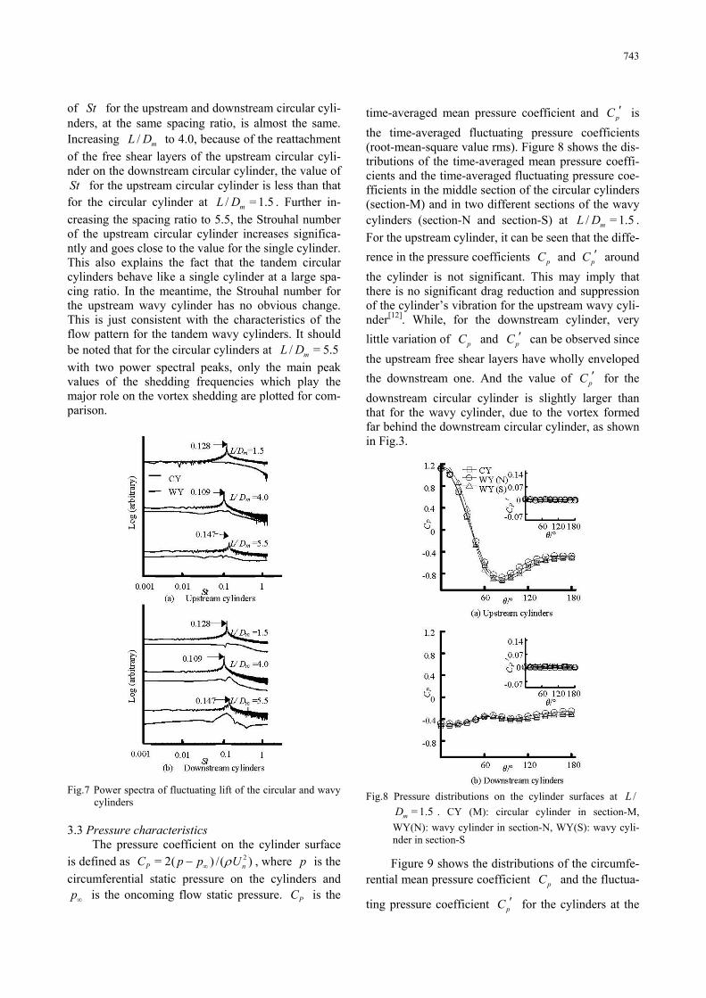
Figures 7 show the power spectra of the fluctua- ting lift and the Strouhal numbers of both the tandem circular and wavy cylinders with / mL D in the range
from 1.5 to 5.5. One can see that the power spectra of the fluctuating lift of the wavy cylinders have no ob- vious peak point as in the case of the circular cyli- nders. Typically for the upstream wavy cylinder at the spacing of / = 1.5mL D , a very low Strouhal number
of 0.0009 is obtained for the upstream wavy cylinder due to the effect of the additional oncoming flow motion on the wavy surface of the wavy cylinder in the spanwise direction. And due to the smaller spacing of / = 1.5mL D , as shown in Fig.3, the vortex she-
dding from the upstream cylinder is inhibited by the downstream cylinder. So the value of St is less than those in the corresponding single cylinder case, which is consistent with the result of Lam et al.[16] for tandem wavy cylinders in turbulent flows. The value
743
of St for the upstream and downstream circular cyli- nders, at the same spacing ratio, is almost the same. Increasing / mL D to 4.0, because of the reattachment
of the free shear layers of the upstream circular cyli- nder on the downstream circular cylinder, the value of St for the upstream circular cylinder is less than that for the circular cylinder at / = 1.5mL D . Further in-
creasing the spacing ratio to 5.5, the Strouhal number of the upstream circular cylinder increases significa- ntly and goes close to the value for the single cylinder. This also explains the fact that the tandem circular cylinders behave like a single cylinder at a large spa- cing ratio. In the meantime, the Strouhal number for the upstream wavy cylinder has no obvious change. This is just consistent with the characteristics of the flow pattern for the tandem wavy cylinders. It should be noted that for the circular cylinders at / = 5.5mL D
with two power spectral peaks, only the main peak values of the shedding frequencies which play the major role on the vortex shedding are plotted for com- parison.
Fig.7 Power spectra of fluctuating lift of the circular and wavy
cylinders 3.3 Pressure characteristics
The pressure coefficient on the cylinder surface is defined as 2= 2( ) /( )P nC p p U , where p is the
circumferential static pressure on the cylinders and p is the oncoming flow static pressure. PC is the
time-averaged mean pressure coefficient and pC is
the time-averaged fluctuating pressure coefficients (root-mean-square value rms). Figure 8 shows the dis- tributions of the time-averaged mean pressure coeffi- cients and the time-averaged fluctuating pressure coe- fficients in the middle section of the circular cylinders (section-M) and in two different sections of the wavy cylinders (section-N and section-S) at / = 1.5mL D .
For the upstream cylinder, it can be seen that the diffe-
rence in the pressure coefficients pC and pC around
the cylinder is not significant. This may imply that there is no significant drag reduction and suppression of the cylinder’s vibration for the upstream wavy cyli- nder[12]. While, for the downstream cylinder, very
little variation of pC and pC can be observed since
the upstream free shear layers have wholly enveloped
the downstream one. And the value of pC for the
downstream circular cylinder is slightly larger than that for the wavy cylinder, due to the vortex formed far behind the downstream circular cylinder, as shown in Fig.3.
Fig.8 Pressure distributions on the cylinder surfaces at /L
= 1.5mD . CY (M): circular cylinder in section-M,
WY(N): wavy cylinder in section-N, WY(S): wavy cyli- nder in section-S
Figure 9 shows the distributions of the circumfe- rential mean pressure coefficient pC and the fluctua-
ting pressure coefficient pC for the cylinders at the

744
Fig.9 Pressure distributions on the cylinder surfaces at /L
= 4.0mD
critical spacing regime of / = 4.0mL D . There is negli-
gible difference in the mean pressure coefficients pC
around the upstream cylinder and the fluctuating pre-
ssure coefficient pC around the downstream cylinder.
For the upstream wavy cylinder, the base pressure coefficient ( pC at = 180o) at section-N is greater
than that of the corresponding upstream circular cyli- nder. This means that the drag force on the upstream wavy cylinders is smaller than that of the upstream circular cylinders[12]. The differences in the back pre- ssure coefficients for the circular and wavy cylinders of the upstream cylinders would result in reduction of the drag force for the upstream wavy cylinders. For
the downstream circular cylinder, a peak value pC is
observed at θ slightly over 60o. This is the result of the upstream free shear layers impinging on the down- stream circular cylinder at that position. The peak in
pC distribution occurs at or very near the separation
point of the shear layer in the case of a laminar sepa- ration. Due to the vortex shedding forming behind the downstream circular cylinder, which can be seen in
Fig.4, pC on the surface of the downstream circular
cylinder is larger than the corresponding downstream wavy cylinder. The phenomena mentioned above also indicate that the spacing ratio / = 4.0mL D is the criti-
cal spacing for tandem circular cylinders.
Fig10 Pressure distributions on the cylinder surfaces at /L
= 5.5mD
The distributions of the mean pressure coefficient
pC and the fluctuating pressure coefficient pC for
the tandem cylinders with a large spacing ratio of /L = 5.5mD are shown in Fig.10. It can be seen that, un-
like tandem wavy cylinders, the distributions of pC
and pC are similar to those for a single cylinder at
the same flow conditions for both the upstream and downstream circular cylinders. The flow patterns for the two tandem circular cylinders also show that they act as two isolated cylinders at such a spacing ratio. And a significant reduction of the drag force as well as the suppression of fluctuating lift occur for the tandem wavy cylinders because of the evident differe- nces in the back pressure coefficients and the fluctua-
ting pressure coefficient pC . Owing to the continuous
impingement of the mature upstream vortices on the
downstream cylinder, a peak value of pC for the
downstream circular cylinder can be seen at around 45o. 3.4 Force characteristics
The three definitions for the different flow patte- rns and the time-averaged circumferential pressure distributions of the cylinders are consistent with the force characteristics on the cylinders. In the present

745
Fig.11 Mean drag coefficients calculations, the drag coefficient DC and the lift coe-
fficient LC are defined as 2= 2 /( )D D mC F U D and 2= 2 /( )L L mC F U D , respectively, where is the
fluid density, DF and LF are the total drag force and
the total lift force. The mean drag coefficients ( )DC
of both wavy and circular cylinders with various spa- cing ratios / mL D are shown in Fig.11. DC of the up-
stream wavy cylinders is slightly smaller than that of the upstream circular cylinders at spacing ratio /L
4mD because of the similar flow patterns and pre-
ssure coefficient distributions. For the large spacing ratio / = 5.5mL D , owing to the mature wake vortex
behind the upstream circular cylinder, DC of the up-
stream circular cylinder is significantly larger than that of the wavy cylinder. However DC of the down-
stream wavy cylinder takes a slightly higher value than that of the corresponding circular cylinder at spacing ratio / 4mL D . This is partly due to the
effect of the reattachment free shear layers from the upstream wavy cylinder to the downstream wavy cyli- nder in section-S. The lower DC of the downstream
cylinder indicates that the downstream cylinder is completely shielded by the upstream cylinder when the spacing is within the critical spacing ratio. Be- cause of the mature wake vortex formed behind the upstream circular cylinder impinging on the down-
stream circular, DC of the downstream cylinder assu-
mes a significant rising.
Fig.12 Fluctuating lift coefficients (rms value)
Figure 12 shows the fluctuating lift coefficient
LC (rms value) for the tandem cylinders. For both
upstream and downstream wavy cylinders, owing to the symmetrical and stable flow patterns, the fluctua-
ting lift coefficient LC are close to 0 at different spa-
cing ratios. While for circular cylinders, because of the mature wake vortex formed behind the upstream cylinder, there is a significant jump at the spacing ratio / = 5.5mL D . All these results confirm that the
wavy cylinders ( / = 6mD and / = 0.15ma D ) are a
suitable choice for drag reduction and vibration sup- pression control for multiple cylinder structures in the laminar flow condition. And such beneficial effect is gradually evident with the increasing spacing ratio /L
mD of the cylinders.
4. Conclusion
In the present investigations, the laminar flows around two wavy cylinders ( / = 6mD and / =ma D
0.15) in the tandem arrangement with a constant Reynolds number of 100 are calculated through the three-dimensional numerical simulations based on the finite volume method. And in this paper, some valua- ble data, such as the drag, the lift, the pressure, the velocity field, the vortex shedding frequency and the

746
flow pattern, are discussed in detail in comparison with a corresponding circular cylinder at the same arrangement. The force coefficients obtained by the three-dimensional numerical simulations show good agreement with the experimental measurements and other published results. It is found that, unlike the quite quasi-two-dimensional flow pattern of the circu- lar cylinders’ wake vortex structures, the wake vorti- ces of the wavy cylinders show a periodic repetition along the spanwise direction. Compared with the tandem circular cylinders at / = 1.5 - 5.5mL D , the
tandem wavy cylinders behave like a single lengthe- ned bluff body without showing the so-called three basic flow patterns. The flow patterns of the tandem wavy cylinders show a very symmetrical and stable distribution until the spacing ratio is increased to /L
= 12.0mD . The critical spacing ratio for the transition
from the narrow gap flow pattern to the vortex impi- ngement flow pattern around the circular cylinders is found to be / = 4.0mL D . When / < 4.0mL D , owing
to the similar flow patterns and pressure coefficient distributions, the effect of the drag reduction as well as the suppression of the fluctuating lift for the tandem wavy cylinders is not significant as compared with circular cylinders. While / > 4.0mL D , which is when
the flow pattern transits to the vortex impingement for circular cylinders, a significant reduction of the drag force as well as the suppression of the fluctuating lift can be seen for the tandem wavy cylinders at =Re 100. References [1] WILLIAMSON C. H. K. Vortex dynamics in the cyli-
nder wake[J]. Annual Review of Fluid Mechanics, 1996, 28: 477-539..
[2] WANG Jia-song. Flow around a circular cylinder using a finite-volume TVD scheme based on a vector trans- formation approach[J]. Journal of Hydrodynamics, 2010, 22(2): 221-228.
[3] LIN J. C., YANG Y. and ROCKWELL D. Flow past two cylinders in tandem: Instantaneous and averaged flow structure[J]. Journal of Fluids and Structures, 2002, 16(8): 1059-1071.
[4] DENG Jian, REN An-lu and ZOU Jian-feng. Three-di- mensional flow around two tandem circular cylinders with various spacings at = 200Re [J]. Journal of Hydrodynamics, Ser. B, 2006, 18(1): 48-54.
[5] JIANG Ren-jie, LIN Jian-zhong. Wall effects on flows past two tandem cylinders of different diameters[J]. Journal of Hydrodynamics, 2012, 24(1): 1-10.
[6] ZDRAVKOVICH M. M. The effects of interference between circular cylinders in cross flow[J]. Journal of Fluids and Structures, 1987, 1(2): 239-261.
[7] XU G., ZHOU Y. Strouhal numbers in the wake of two inline cylinders[J]. Experiments in Fluids, 2004, 37(2): 248-256.
[8] ZHOU Y., YIU M. W. Flow structure, momentum and heat transport in a two-tandem-cylinder wake[J]. Jour- nal of Fluid Mechanics, 2006, 548: 17-48.
[9] CARMO B. S., MENEGHINI J. R. and SHERWIN S. J. Possible states in the flow around two circular cylinders in tandem with separations in the vicinity of the drag in- version spacing[J]. Physics of Fluids, 2010, 22(5): 054101.
[10] CARMO B. S., MENEGHINI J. R. and SHERWIN S. J. Secondary instabilities in the flow around two circular cylinders in tandem[J]. Journal of Fluid Mechanics, 2010, 644: 395-431.
[11] SUMNER D. Two circular cylinders in cross-flow: A review[J]. Journal of Fluids and Structures, 2010, 26(6): 849-899.
[12] LAM K., LIN Y. F. Large eddy simulation of flow around wavy cylinders at a subcritical Reynolds number[J]. International Journal of Heat and Fluid Flow, 2008, 29(4): 1071-1088.
[13] LAM K., LIN Y. F. Effects of wavelength and ampli- tude of a wavy cylinder in cross-flow at low Reynolds numbers[J]. Journal of Fluid Mechanics, 2009, 620: 195-220.
[14] LAM K., LIN Y. F. and ZOU L. et al. Experimental study and large eddy simulation of turbulent flow around tube bundles composed of wavy and circular cylinders[J]. International Journal of Heat and Fluid Flow, 2010, 31(1): 32-44.
[15] LAM K., LIN Y. F. and ZOU L. et al. Investigation of turbulent flow past a yawed wavy cylinder[J]. Journal of Fluids and Structures, 2010, 26(7-8): 1078-1097.
[16] LAM K., LIN Y. F. and ZOU L. et al. Numerical simu- lation of flows around two unyawed and yawed wavy cylinders in tandem arrangement[J]. Journal of Fluids and Structures, 2012, 28(1): 135-151.
[17] ALAM M. M., MORIYA M. and TAKAI K. et al. Flu- ctuating fluid forces acting on two circular cylinders in a tandem arrangement at a subcritical Reynolds number[J]. Journal of Wind Engineering and Indu- strial Aerodynamics, 2003, 91(1-2): 139-154.
[18] SHARMAN B., LIEN F. S. and DAVIDSON L. et al. Numerical predictions of low Reynolds number flows over two tandem circular cylinders[J]. International Journal for Numerical Methods in Fluids, 2005, 47(5): 423-447.