Embed Size (px)
Citation preview
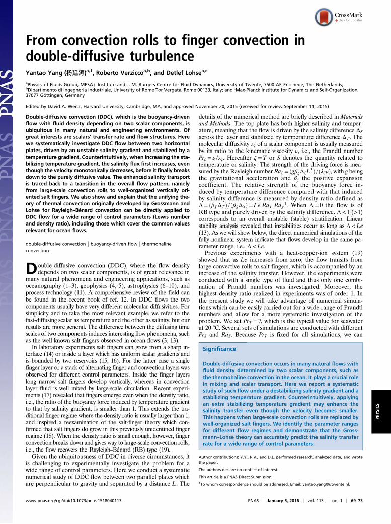
From convection rolls to finger convection indouble-diffusive turbulenceYantao Yang (杨延涛)a,1, Roberto Verziccoa,b, and Detlef Lohsea,c
aPhysics of Fluids Group, MESA+ Institute and J. M. Burgers Centre for Fluid Dynamics, University of Twente, 7500 AE Enschede, The Netherlands;bDipartimento di Ingegneria Industriale, University of Rome Tor Vergata, Rome 00133, Italy; and cMax-Planck Institute for Dynamics and Self-Organization,37077 Göttingen, Germany
Edited by David A. Weitz, Harvard University, Cambridge, MA, and approved November 20, 2015 (received for review September 11, 2015)
Double-diffusive convection (DDC), which is the buoyancy-drivenflow with fluid density depending on two scalar components, isubiquitous in many natural and engineering environments. Ofgreat interests are scalars’ transfer rate and flow structures. Herewe systematically investigate DDC flow between two horizontalplates, driven by an unstable salinity gradient and stabilized by atemperature gradient. Counterintuitively, when increasing the sta-bilizing temperature gradient, the salinity flux first increases, eventhough the velocity monotonically decreases, before it finally breaksdown to the purely diffusive value. The enhanced salinity transportis traced back to a transition in the overall flow pattern, namelyfrom large-scale convection rolls to well-organized vertically ori-ented salt fingers. We also show and explain that the unifying the-ory of thermal convection originally developed by Grossmann andLohse for Rayleigh–Bénard convection can be directly applied toDDC flow for a wide range of control parameters (Lewis numberand density ratio), including those which cover the common valuesrelevant for ocean flows.
double-diffusive convection | buoyancy-driven flow | thermohalineconvection
Double-diffusive convection (DDC), where the flow densitydepends on two scalar components, is of great relevance in
many natural phenomena and engineering applications, such asoceanography (1–3), geophysics (4, 5), astrophysics (6–10), andprocess technology (11). A comprehensive review of the field canbe found in the recent book of ref. 12. In DDC flows the twocomponents usually have very different molecular diffusivities. Forsimplicity and to take the most relevant example, we refer to thefast-diffusing scalar as temperature and the other as salinity, but ourresults are more general. The difference between the diffusing timescales of two components induces interesting flow phenomena, suchas the well-known salt fingers observed in ocean flows (3, 13).In laboratory experiments salt fingers can grow from a sharp in-
terface (14) or inside a layer which has uniform scalar gradients andis bounded by two reservoirs (15, 16). For the latter case a singlefinger layer or a stack of alternating finger and convection layers wasobserved for different control parameters. Inside the finger layerslong narrow salt fingers develop vertically, whereas in convectionlayer fluid is well mixed by large-scale circulation. Recent experi-ments (17) revealed that fingers emerge even when the density ratio,i.e., the ratio of the buoyancy force induced by temperature gradientto that by salinity gradient, is smaller than 1. This extends the tra-ditional finger regime where the density ratio is usually larger than 1,and inspired a reexamination of the salt-finger theory which con-firmed that salt fingers do grow in this previously unidentified fingerregime (18). When the density ratio is small enough, however, fingerconvection breaks down and gives way to large-scale convection rolls,i.e., the flow recovers the Rayleigh–Bénard (RB) type (19).Given the ubiquitousness of DDC in diverse circumstances, it
is challenging to experimentally investigate the problem for awide range of control parameters. Here we conduct a systematicnumerical study of DDC flow between two parallel plates whichare perpendicular to gravity and separated by a distance L. The
details of the numerical method are briefly described in Materialsand Methods. The top plate has both higher salinity and temper-ature, meaning that the flow is driven by the salinity difference ΔSacross the layer and stabilized by temperature difference ΔT. Themolecular diffusivity λζ of a scalar component is usually measuredby its ratio to the kinematic viscosity ν, i.e., the Prandtl numberPrζ = ν=λζ. Hereafter ζ=T or S denotes the quantity related totemperature or salinity. The strength of the driving force is mea-sured by the Rayleigh number Raζ = ðgβζΔζL3Þ=ðλζνÞ, with g beingthe gravitational acceleration and βζ the positive expansioncoefficient. The relative strength of the buoyancy force in-duced by temperature difference compared with that inducedby salinity difference is measured by density ratio defined asΛ= ðβTΔTÞ=ðβSΔSÞ=Le RaT Ra−1S . When Λ= 0 the flow is ofRB type and purely driven by the salinity difference. Λ< 1 (>1)corresponds to an overall unstable (stable) stratification. Linearstability analysis revealed that instabilities occur as long as Λ<Le(13). As we will show below, the direct numerical simulations of thefully nonlinear system indicate that flows develop in the same pa-rameter range, i.e., Λ<Le.Previous experiments with a heat-copper-ion system (19)
showed that as Le increases from zero, the flow transits fromlarge convective rolls to salt fingers, which is accompanied by anincrease of the salinity transfer. However, the experiments wereconducted with a single type of fluid and thus only one combi-nation of Prandtl numbers was investigated. Moreover, thehighest density ratio realized in experiments was of order 1. Inthe present study we will take advantage of numerical simula-tions which can be easily carried out for a wide range of Prandtlnumbers and allow for a more systematic investigation of theproblem. We set PrT = 7, which is the typical value for seawaterat 20 °C. Several sets of simulations are conducted with differentPrS and RaS. Because PrT is fixed for all simulations, we can
Significance
Double-diffusive convection occurs in many natural flows withfluid density determined by two scalar components, such asthe thermohaline convection in the ocean. It plays a crucial rolein mixing and scalar transport. Here we report a systematicstudy of such flow under a destabilizing salinity gradient and astabilizing temperature gradient. Counterintuitively, applyingan extra stabilizing temperature gradient may enhance thesalinity transfer even though the velocity becomes smaller.This happens when large-scale convection rolls are replaced bywell-organized salt fingers. We identify the parameter rangesfor different flow regimes and demonstrate that the Gross-mann–Lohse theory can accurately predict the salinity transferrate for a wide range of control parameters.
Author contributions: Y.Y., R.V., and D.L. performed research, analyzed data, and wrotethe paper.
The authors declare no conflict of interest.
This article is a PNAS Direct Submission.1To whom correspondence should be addressed. Email: [email protected].
www.pnas.org/cgi/doi/10.1073/pnas.1518040113 PNAS | January 5, 2016 | vol. 113 | no. 1 | 69–73
PHYS
ICS
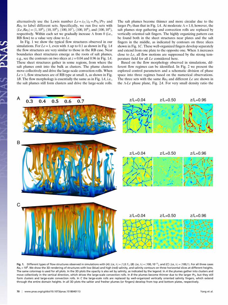
alternatively use the Lewis number Le= λT=λS =PrS=PrT andRaS to label different sets. Specifically, we run five sets withðLe,RaSÞ= ð1, 108Þ, ð10, 108Þ, ð100, 107Þ, ð100, 108Þ, and ð100, 109Þ,respectively. Within each set we gradually increase Λ from 0 (i.e.,RB flow) to a value very close to Le.In Fig. 1 we show the typical flow structures observed in our
simulations. For Le= 1, even with Λ up to 0.1 as shown in Fig. 1Athe flow structures are very similar to those in the RB case. Nearboundaries sheet structures emerge as the roots of salt plumes,e.g., see the contours on two slices at z= 0.04 and 0.96 in Fig. 1A.These sheet structures gather in some regions, from where thesalt plumes emit into the bulk as clusters. The plume clustersmove collectively and drive the large-scale convection rolls. WhenLe> 1, flow structures are of RB type at small Λ, as shown in Fig.1B. The flow morphology is essentially the same as in Fig. 1A, i.e.,the salt plumes still form clusters and drive the large-scale rolls.
The salt plumes become thinner and more circular due to thelarger PrS than that in Fig. 1A. At moderate Λ= 1.0, however, thesalt plumes stop gathering and convection rolls are replaced byvertically oriented salt fingers. The highly organizing pattern canbe found both in the sheet structures near plates and the saltfingers in the middle, as indicated by contours on three slicesshown in Fig. 1C. These well-organized fingers develop separatelyand extend from one plate to the opposite one. When Λ increasesclose to Le, all flow motions are suppressed by the strong tem-perature field for all Le considered here.Based on the flow morphology observed in simulations, dif-
ferent flow regimes can be identified. In Fig. 2 we present theexplored control parameters and a schematic division of phasespace into three regimes based on the numerical observations.The three sets with the same RaS and different Le are shown inthe Λ-Le phase plane, Fig. 2A. For very small density ratio the
A
B
C
Fig. 1. Different types of flow structures observed in simulations with (A) ðLe,ΛÞ= ð1,0.1Þ, (B) ðLe,ΛÞ= ð100, 10−3Þ, and (C) ðLe,ΛÞ= ð100,1Þ. For all three casesRaS = 108. We show the 3D rendering of structures with low (blue) and high (red) salinity, and salinity contours on three horizontal slices at different heights.The same colormap is used for all plots. In the 3D plots the opacity is also set by salinity, as indicated by the legend. In A the plumes gather into clusters andmove collectively in the vertical direction, which drives the large-scale convection rolls. In B the plumes become thinner due to the larger PrS, but they stillform clusters and large-scale convection rolls. In C the large-scale rolls are replaced by well-organized vertically oriented salinity fingers, which extendthrough the entire domain heights. In all 3D plots the saltier and fresher plumes (or fingers) develop from top and bottom plates, respectively.
70 | www.pnas.org/cgi/doi/10.1073/pnas.1518040113 Yang et al.
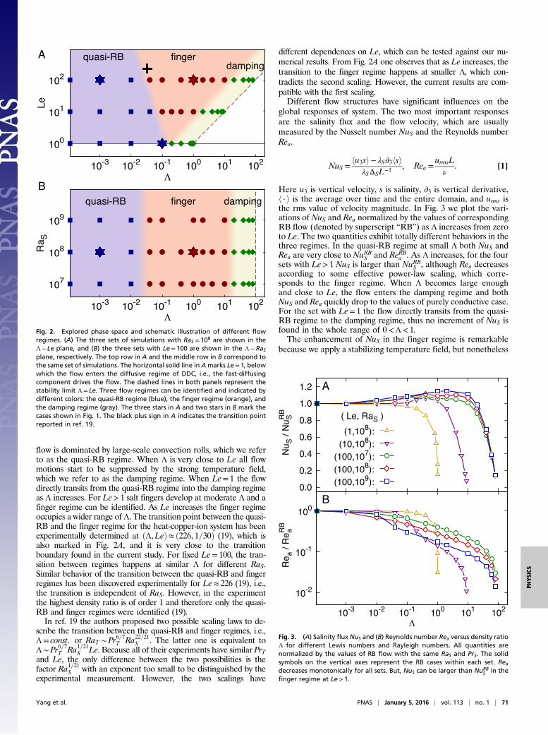
flow is dominated by large-scale convection rolls, which we referto as the quasi-RB regime. When Λ is very close to Le all flowmotions start to be suppressed by the strong temperature field,which we refer to as the damping regime. When Le= 1 the flowdirectly transits from the quasi-RB regime into the damping regimeas Λ increases. For Le> 1 salt fingers develop at moderate Λ and afinger regime can be identified. As Le increases the finger regimeoccupies a wider range of Λ. The transition point between the quasi-RB and the finger regime for the heat-copper-ion system has beenexperimentally determined at ðΛ,LeÞ≈ ð226, 1=30Þ (19), which isalso marked in Fig. 2A, and it is very close to the transitionboundary found in the current study. For fixed Le= 100, the tran-sition between regimes happens at similar Λ for different RaS.Similar behavior of the transition between the quasi-RB and fingerregimes has been discovered experimentally for Le≈ 226 (19), i.e.,the transition is independent of RaS. However, in the experimentthe highest density ratio is of order 1 and therefore only the quasi-RB and finger regimes were identified (19).In ref. 19 the authors proposed two possible scaling laws to de-
scribe the transition between the quasi-RB and finger regimes, i.e.,Λ= const. or RaT ∼Pr6=7T Ra22=21S . The latter one is equivalent toΛ∼Pr6=7T Ra1=21S Le. Because all of their experiments have similar PrTand Le, the only difference between the two possibilities is thefactor Ra1=21S with an exponent too small to be distinguished by theexperimental measurement. However, the two scalings have
different dependences on Le, which can be tested against our nu-merical results. From Fig. 2A one observes that as Le increases, thetransition to the finger regime happens at smaller Λ, which con-tradicts the second scaling. However, the current results are com-patible with the first scaling.Different flow structures have significant influences on the
global responses of system. The two most important responsesare the salinity flux and the flow velocity, which are usuallymeasured by the Nusselt number NuS and the Reynolds numberRea.
NuS =hu3si− λS∂3hsi
λSΔSL−1 , Rea =urmsLν
. [1]
Here u3 is vertical velocity, s is salinity, ∂3 is vertical derivative,h · i is the average over time and the entire domain, and urms isthe rms value of velocity magnitude. In Fig. 3 we plot the vari-ations of NuS and Rea normalized by the values of correspondingRB flow (denoted by superscript “RB”) as Λ increases from zeroto Le. The two quantities exhibit totally different behaviors in thethree regimes. In the quasi-RB regime at small Λ both NuS andRea are very close to NuRBS and ReRBa . As Λ increases, for the foursets with Le> 1 NuS is larger than NuRBS , although Rea decreasesaccording to some effective power-law scaling, which corre-sponds to the finger regime. When Λ becomes large enoughand close to Le, the flow enters the damping regime and bothNuS and Rea quickly drop to the values of purely conductive case.For the set with Le= 1 the flow directly transits from the quasi-RB regime to the damping regime, thus no increment of NuS isfound in the whole range of 0<Λ< 1.The enhancement of NuS in the finger regime is remarkable
because we apply a stabilizing temperature field, but nonetheless
A
B
Fig. 2. Explored phase space and schematic illustration of different flowregimes. (A) The three sets of simulations with RaS = 108 are shown in theΛ− Le plane, and (B) the three sets with Le= 100 are shown in the Λ−RaSplane, respectively. The top row in A and the middle row in B correspond tothe same set of simulations. The horizontal solid line in Amarks Le= 1, belowwhich the flow enters the diffusive regime of DDC, i.e., the fast-diffusingcomponent drives the flow. The dashed lines in both panels represent thestability limit Λ= Le. Three flow regimes can be identified and indicated bydifferent colors: the quasi-RB regime (blue), the finger regime (orange), andthe damping regime (gray). The three stars in A and two stars in B mark thecases shown in Fig. 1. The black plus sign in A indicates the transition pointreported in ref. 19.
A
B
Fig. 3. (A) Salinity flux NuS and (B) Reynolds number Rea versus density ratioΛ for different Lewis numbers and Rayleigh numbers. All quantities arenormalized by the values of RB flow with the same RaS and PrS. The solidsymbols on the vertical axes represent the RB cases within each set. Readecreases monotonically for all sets. But, NuS can be larger than NuRB
S in thefinger regime at Le> 1.
Yang et al. PNAS | January 5, 2016 | vol. 113 | no. 1 | 71
PHYS
ICS
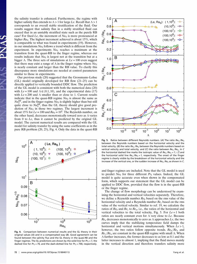
the salinity transfer is enhanced. Furthermore, the regime withhigher salinity flux extends to Λ> 1 for large Le. Recall that Λ> 1corresponds to an overall stable stratification of the fluid. Ourresults suggest that salinity flux in a stably stratified fluid canexceed that in an unstably stratified state such as the purely RBcase! For fixed Le, the increment of NuS is more pronounced athigher RaS. The highest increment achieved is about 15%, whichis comparable to what was found in experiments (19). However,in our simulations NuS follows a trend which is different from theexperiment. In experiments NuS reaches a maximum at thetransition from the quasi-RB to the finger regime, whereas ourresults indicate that NuS is largest not at the transition but at abigger Λ. The three sets of simulations at Le= 100 even suggestthat there may exist a range of Λ in the finger regime where NuSis nearly constant and larger than the RB value. To clarify thisdiscrepancy more simulations are needed at control parameterssimilar to those in experiments.Our previous study (20) suggested that the Grossmann–Lohse
(GL) model originally developed for RB flow (21–25) can bedirectly applied to vertically bounded DDC flow. The predictionof the GL model is consistent with both the numerical data (20)with Le= 100 and Λ∈ ð0.1, 10Þ, and the experimental data (17)with Le≈ 200 and Λ smaller than or close to 1. Current resultsindicate that in the quasi-RB regime NuS is almost the same asNuRBS , and in the finger regime NuS is slightly higher than but stillquite close to NuRBS , thus the GL theory should give good pre-diction of NuS in those two regimes. The largest increment isabout 15% for Le= 100 and RaS = 109. The Reynolds number, onthe other hand, decreases monotonically toward zero as Λ variesfrom 0 to Le, thus it cannot be predicted by the original GLmodel. The current numerical results are compared with the GLmodel for salinity transfer by using the same coefficients as in thepure RB problem (20, 25), Fig. 4. Only the data in the quasi-RB
and finger regimes are included. Note that the GL model is usedto predict NuS for three different PrS values. Indeed, the GLmodel is quite accurate even when shown in the compensatedform, which supports our statement that the GL model can beapplied to DDC flow, provided that the flow is in the quasi-RBor the finger regime.The change of flow morphology can be understood by exam-
ining the horizontal and vertical velocities separately. Therefore,we define a Reynolds number Reh based on the rms value of thehorizontal velocity and a Reynolds number Rez based on the rmsvalue of the vertical velocity. Similar to ref. 19, we calculate theratios of Reh and Rez to Rea, i.e., the ratios of the horizontal andvertical velocities to the total velocity, Fig. 5. For Le= 1 bothratios are nearly constant even for Λ very close to Le. BecauseRea decreases monotonically to zero as Λ approaches Le, the twocurves imply that the stabilizing temperature field damps thehorizontal and vertical motions simultaneously. When Le> 1,however, the two ratios follow opposite trends. Reh=Rea andRez=Rea are constant in the quasi-RB regime with small Λ. WhenΛ further increases, the former decreases to as low as 0.1 and thelatter increases to almost 1, implying that the fluid moves mainlyin the vertical direction and therefore transfers salinity more
A
B
Fig. 4. Comparison between numerical results and the GL theory in theiroriginal values (A) and in a compensated way (B). Good agreement can befound between the salinity flux and the GL theory in the quasi-RB and thefinger regimes. The GL predictions are shown by the solid line for PrS = 7, thedashed line for PrS = 70, and the dash-dotted line for PrS = 700, respectively.
A
B
C
Fig. 5. Ratios between different Reynolds numbers. (A) The ratio Reh=Reabetween the Reynolds numbers based on the horizontal velocity and thetotal velocity, (B) the ratio Rez=Rea between the Reynolds numbers based onvertical velocity and total velocity, and (C) the ratio between Rez=Reh. In Cthe horizontal dashed line marks the isotropic value of Rez=Reh = 1=
ffiffiffi2
pand
the horizontal solid line Rez=Reh = 1, respectively. The onset of the fingerregime is clearly visible by the breakdown of the horizontal velocity and theincrease of the vertical one, or the sudden increase of Rez=Reh as shown in C.
72 | www.pnas.org/cgi/doi/10.1073/pnas.1518040113 Yang et al.
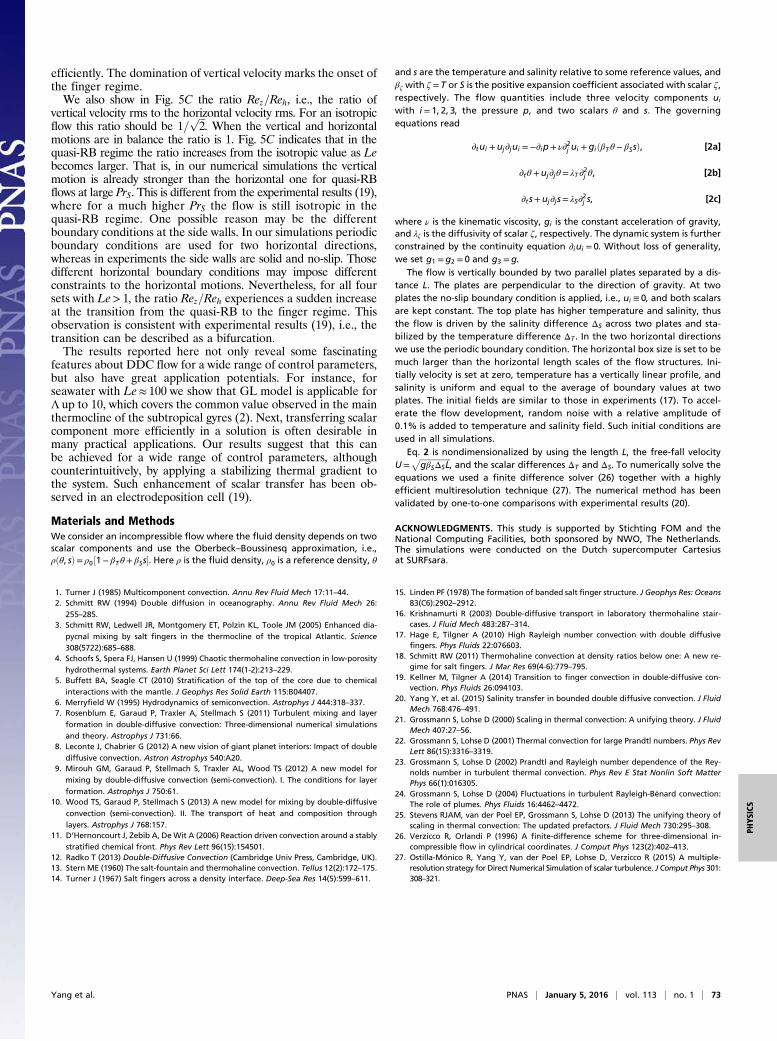
efficiently. The domination of vertical velocity marks the onset ofthe finger regime.We also show in Fig. 5C the ratio Rez=Reh, i.e., the ratio of
vertical velocity rms to the horizontal velocity rms. For an isotropicflow this ratio should be 1=
ffiffiffi2
p. When the vertical and horizontal
motions are in balance the ratio is 1. Fig. 5C indicates that in thequasi-RB regime the ratio increases from the isotropic value as Lebecomes larger. That is, in our numerical simulations the verticalmotion is already stronger than the horizontal one for quasi-RBflows at large PrS. This is different from the experimental results (19),where for a much higher PrS the flow is still isotropic in thequasi-RB regime. One possible reason may be the differentboundary conditions at the side walls. In our simulations periodicboundary conditions are used for two horizontal directions,whereas in experiments the side walls are solid and no-slip. Thosedifferent horizontal boundary conditions may impose differentconstraints to the horizontal motions. Nevertheless, for all foursets with Le> 1, the ratio Rez=Reh experiences a sudden increaseat the transition from the quasi-RB to the finger regime. Thisobservation is consistent with experimental results (19), i.e., thetransition can be described as a bifurcation.The results reported here not only reveal some fascinating
features about DDC flow for a wide range of control parameters,but also have great application potentials. For instance, forseawater with Le≈ 100 we show that GL model is applicable forΛ up to 10, which covers the common value observed in the mainthermocline of the subtropical gyres (2). Next, transferring scalarcomponent more efficiently in a solution is often desirable inmany practical applications. Our results suggest that this canbe achieved for a wide range of control parameters, althoughcounterintuitively, by applying a stabilizing thermal gradient tothe system. Such enhancement of scalar transfer has been ob-served in an electrodeposition cell (19).
Materials and MethodsWe consider an incompressible flow where the fluid density depends on twoscalar components and use the Oberbeck–Boussinesq approximation, i.e.,ρðθ, sÞ= ρ0½1− βTθ+ βSs�. Here ρ is the fluid density, ρ0 is a reference density, θ
and s are the temperature and salinity relative to some reference values, andβζ with ζ = T or S is the positive expansion coefficient associated with scalar ζ,respectively. The flow quantities include three velocity components ui
with i= 1, 2, 3, the pressure p, and two scalars θ and s. The governingequations read
∂tui +uj∂jui =−∂ip+ ν∂2j ui +giðβTθ− βSsÞ, [2a]
∂tθ+uj∂jθ= λT ∂2j θ, [2b]
∂t s+uj∂j s= λS∂2j s, [2c]
where ν is the kinematic viscosity, gi is the constant acceleration of gravity,and λζ is the diffusivity of scalar ζ, respectively. The dynamic system is furtherconstrained by the continuity equation ∂iui = 0. Without loss of generality,we set g1 =g2 = 0 and g3 =g.
The flow is vertically bounded by two parallel plates separated by a dis-tance L. The plates are perpendicular to the direction of gravity. At twoplates the no-slip boundary condition is applied, i.e., ui ≡ 0, and both scalarsare kept constant. The top plate has higher temperature and salinity, thusthe flow is driven by the salinity difference ΔS across two plates and sta-bilized by the temperature difference ΔT . In the two horizontal directionswe use the periodic boundary condition. The horizontal box size is set to bemuch larger than the horizontal length scales of the flow structures. Ini-tially velocity is set at zero, temperature has a vertically linear profile, andsalinity is uniform and equal to the average of boundary values at twoplates. The initial fields are similar to those in experiments (17). To accel-erate the flow development, random noise with a relative amplitude of0.1% is added to temperature and salinity field. Such initial conditions areused in all simulations.
Eq. 2 is nondimensionalized by using the length L, the free-fall velocityU=
ffiffiffiffiffiffiffiffiffiffiffiffiffiffiffiffigβSΔSL
p, and the scalar differences ΔT and ΔS. To numerically solve the
equations we used a finite difference solver (26) together with a highlyefficient multiresolution technique (27). The numerical method has beenvalidated by one-to-one comparisons with experimental results (20).
ACKNOWLEDGMENTS. This study is supported by Stichting FOM and theNational Computing Facilities, both sponsored by NWO, The Netherlands.The simulations were conducted on the Dutch supercomputer Cartesiusat SURFsara.
1. Turner J (1985) Multicomponent convection. Annu Rev Fluid Mech 17:11–44.2. Schmitt RW (1994) Double diffusion in oceanography. Annu Rev Fluid Mech 26:
255–285.3. Schmitt RW, Ledwell JR, Montgomery ET, Polzin KL, Toole JM (2005) Enhanced dia-
pycnal mixing by salt fingers in the thermocline of the tropical Atlantic. Science
308(5722):685–688.4. Schoofs S, Spera FJ, Hansen U (1999) Chaotic thermohaline convection in low-porosity
hydrothermal systems. Earth Planet Sci Lett 174(1-2):213–229.5. Buffett BA, Seagle CT (2010) Stratification of the top of the core due to chemical
interactions with the mantle. J Geophys Res Solid Earth 115:B04407.6. Merryfield W (1995) Hydrodynamics of semiconvection. Astrophys J 444:318–337.7. Rosenblum E, Garaud P, Traxler A, Stellmach S (2011) Turbulent mixing and layer
formation in double-diffusive convection: Three-dimensional numerical simulations
and theory. Astrophys J 731:66.8. Leconte J, Chabrier G (2012) A new vision of giant planet interiors: Impact of double
diffusive convection. Astron Astrophys 540:A20.9. Mirouh GM, Garaud P, Stellmach S, Traxler AL, Wood TS (2012) A new model for
mixing by double-diffusive convection (semi-convection). I. The conditions for layer
formation. Astrophys J 750:61.10. Wood TS, Garaud P, Stellmach S (2013) A new model for mixing by double-diffusive
convection (semi-convection). II. The transport of heat and composition through
layers. Astrophys J 768:157.11. D’Hernoncourt J, Zebib A, DeWit A (2006) Reaction driven convection around a stably
stratified chemical front. Phys Rev Lett 96(15):154501.12. Radko T (2013) Double-Diffusive Convection (Cambridge Univ Press, Cambridge, UK).13. Stern ME (1960) The salt-fountain and thermohaline convection. Tellus 12(2):172–175.14. Turner J (1967) Salt fingers across a density interface. Deep-Sea Res 14(5):599–611.
15. Linden PF (1978) The formation of banded salt finger structure. J Geophys Res: Oceans83(C6):2902–2912.
16. Krishnamurti R (2003) Double-diffusive transport in laboratory thermohaline stair-cases. J Fluid Mech 483:287–314.
17. Hage E, Tilgner A (2010) High Rayleigh number convection with double diffusivefingers. Phys Fluids 22:076603.
18. Schmitt RW (2011) Thermohaline convection at density ratios below one: A new re-gime for salt fingers. J Mar Res 69(4-6):779–795.
19. Kellner M, Tilgner A (2014) Transition to finger convection in double-diffusive con-vection. Phys Fluids 26:094103.
20. Yang Y, et al. (2015) Salinity transfer in bounded double diffusive convection. J FluidMech 768:476–491.
21. Grossmann S, Lohse D (2000) Scaling in thermal convection: A unifying theory. J FluidMech 407:27–56.
22. Grossmann S, Lohse D (2001) Thermal convection for large Prandtl numbers. Phys RevLett 86(15):3316–3319.
23. Grossmann S, Lohse D (2002) Prandtl and Rayleigh number dependence of the Rey-nolds number in turbulent thermal convection. Phys Rev E Stat Nonlin Soft MatterPhys 66(1):016305.
24. Grossmann S, Lohse D (2004) Fluctuations in turbulent Rayleigh-Bénard convection:The role of plumes. Phys Fluids 16:4462–4472.
25. Stevens RJAM, van der Poel EP, Grossmann S, Lohse D (2013) The unifying theory ofscaling in thermal convection: The updated prefactors. J Fluid Mech 730:295–308.
26. Verzicco R, Orlandi P (1996) A finite-difference scheme for three-dimensional in-compressible flow in cylindrical coordinates. J Comput Phys 123(2):402–413.
27. Ostilla-Mónico R, Yang Y, van der Poel EP, Lohse D, Verzicco R (2015) A multiple-resolution strategy for Direct Numerical Simulation of scalar turbulence. J Comput Phys 301:308–321.
Yang et al. PNAS | January 5, 2016 | vol. 113 | no. 1 | 73
PHYS
ICS