Embed Size (px)
Citation preview
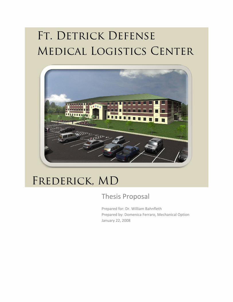
Frederick, MD
Thesis Proposal Prepared for: Dr. William Bahnfleth Prepared by: Domenica Ferraro, Mechanical Option January 22, 2008
Ft. Detrick Defense
Medical Logistics Center
Ft. Detrick Defense Medical Logistics Center
Mechanical Systems Existing Conditions Report
January 22, 2007
Domenica Ferraro | Mechanical Option
2
Table of Contents
Executive Summary ......................................................................................................................... 3
Building Design Overview ............................................................................................................... 4
Mechanical Systems Description .................................................................................................... 5
Problem Statement ......................................................................................................................... 7
Redesign Alternatives ..................................................................................................................... 8
Proposed Redesign ......................................................................................................................... 9
Breadth Topics .............................................................................................................................. 10
Tasks and Tools ............................................................................................................................. 11
Conclusions ................................................................................................................................... 12
Preliminary Research/References................................................................................................. 12
Appendix A – Spring 2008 Schedule ............................................................................................. 14
Ft. Detrick Defense Medical Logistics Center
Mechanical Systems Existing Conditions Report
December 14, 2007
Domenica Ferraro | Mechanical Option
3
Executive summary
Ft. Detrick Defense Medical Logistics Center (DMLC) is a three‐story office building located on the Ft. Detrick military base in Frederick, MD. The building is 129,960 square feet and it houses the top medical planning organizations within the Department of Defense representing the Army, Navy, Air Force, and Marines. It was designed to meet ASHRAE 62.1 and ASHRAE 90.1 for indoor air quality and energy efficiency, and it was also designed for occupant safety in the incidence of a terrorist attack.
A complete heating, ventilating, and air conditioning system with DDC controls is provided for Ft. Detrick. Two gas‐fired boilers, two inline boiler circulation pumps, and two variable speed pumps provide hot water to the building. A decoupled loop system with two rotary screw water‐cooled chillers, two constant volume evaporator pumps, and two variable volume pumps provide chilled water to the building. Condenser water is provided via two induced‐draft cooling towers and two constant volume condenser pumps. The building’s VAV reheat boxes are served by six AHUs during regular operation and one emergency AHU that runs by generator power. The glycol system serves air conditioning units in the communication rooms and the emergency AHU with a drycooler. The systems are appropriate for their application, but improvements can be made to increase energy efficiency and occupant comfort.
Energy consumption can be reduced with a dedicated outdoor air system (DOAS). A DOAS may also decrease the number of air handlers required for operation. The DOAS will dehumidify the space, which improves indoor air quality. Active chilled beams as a cooling system will be used. This is feasible for an office space because they can easily be incorporated into the ceiling grid. Since Ft. Detrick is a military structure, security is an important issue, as was previously stated. A second part of this depth study will examine how well the building removes contaminates and what ways the building can improve its filtering system.
The structural and electrical systems will also be analyzed to determine if the redesign has impact on these systems. Tools used for this will be the manual for steel construction, R.S. Means, and Microsoft Excel. Tools for the mechanical analysis will include Trane Trace 700 for load and energy calculations, manufacturer’s data to determine size, cost, and capacity, and the SPiRiT rating system for recalculating sustainability. With the redesign of mechanical, structural, and electrical systems, Ft. Detrick will hopefully have a better solution to the design requirements.
Ft. Detrick Defense Medical Logistics Center
Mechanical Systems Existing Conditions Report
January 22, 2007
Domenica Ferraro | Mechanical Option
4
Building Design Overview
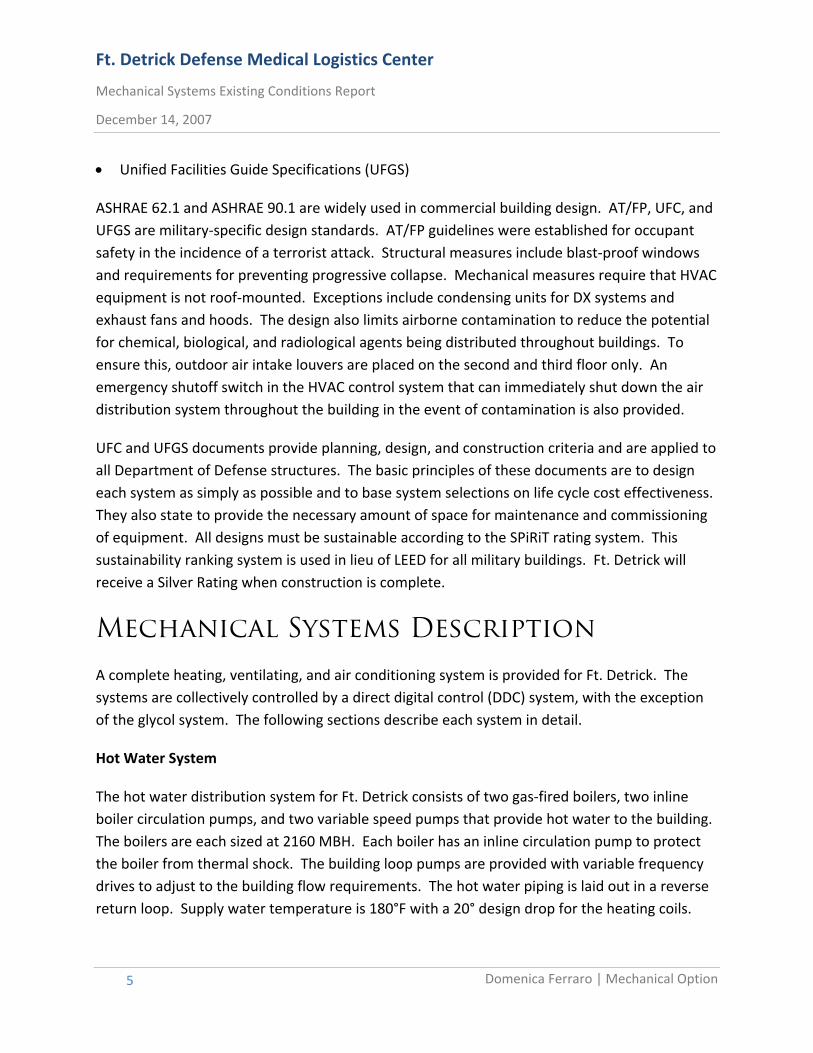
Ft. Detrick Defense Medical Logistics Center (DMLC) is a three‐story office building located on the Ft. Detrick military base in Frederick, MD. The building is 129,960 square feet and it houses the top medical planning organizations within the Department of Defense representing the Army, Navy, Air Force, and Marines. Figure 1 shows an area breakdown of the building and displays space relationships. As seen in this figure, the majority of the building consists of open office space. This minimizes the area needed strictly for circulation space. Mechanical rooms housing the building’s seven air handling units (AHUs) are located at the north and south ends of the buildings. The central plant is located in the southwest corner of the first floor.
Figure 1 – Space Relationship & Area Breakdown Diagram
First Floor Second Floor Third Floor
The mechanical engineer for Ft. Detrick, Baker and Associates, designed the building in accordance with the following specifications:
• ASHRAE 62‐2004: Ventilation for Acceptable Indoor Air Quality
• ASHRAE 90.1‐2004: Energy Efficient Design of New Buildings Except Low‐Rise Residential Buildings
• Unified Facilities Criteria (UFC) 4‐010‐01: Anti‐Terrorism/Force Protection (AT/FP) Standards
• UFC 3‐410‐01FA‐Design: Heating, Ventilation, and Air Conditioning
• UFC 3‐410‐02A‐Design: HVAC Control Systems
Ft. Detrick Defense Medical Logistics Center
Mechanical Systems Existing Conditions Report
December 14, 2007
Domenica Ferraro | Mechanical Option
5
• Unified Facilities Guide Specifications (UFGS)
ASHRAE 62.1 and ASHRAE 90.1 are widely used in commercial building design. AT/FP, UFC, and UFGS are military‐specific design standards. AT/FP guidelines were established for occupant safety in the incidence of a terrorist attack. Structural measures include blast‐proof windows and requirements for preventing progressive collapse. Mechanical measures require that HVAC equipment is not roof‐mounted. Exceptions include condensing units for DX systems and exhaust fans and hoods. The design also limits airborne contamination to reduce the potential for chemical, biological, and radiological agents being distributed throughout buildings. To ensure this, outdoor air intake louvers are placed on the second and third floor only. An emergency shutoff switch in the HVAC control system that can immediately shut down the air distribution system throughout the building in the event of contamination is also provided.
UFC and UFGS documents provide planning, design, and construction criteria and are applied to all Department of Defense structures. The basic principles of these documents are to design each system as simply as possible and to base system selections on life cycle cost effectiveness. They also state to provide the necessary amount of space for maintenance and commissioning of equipment. All designs must be sustainable according to the SPiRiT rating system. This sustainability ranking system is used in lieu of LEED for all military buildings. Ft. Detrick will receive a Silver Rating when construction is complete.
Mechanical Systems Description
A complete heating, ventilating, and air conditioning system is provided for Ft. Detrick. The systems are collectively controlled by a direct digital control (DDC) system, with the exception of the glycol system. The following sections describe each system in detail.
Hot Water System
The hot water distribution system for Ft. Detrick consists of two gas‐fired boilers, two inline boiler circulation pumps, and two variable speed pumps that provide hot water to the building. The boilers are each sized at 2160 MBH. Each boiler has an inline circulation pump to protect the boiler from thermal shock. The building loop pumps are provided with variable frequency drives to adjust to the building flow requirements. The hot water piping is laid out in a reverse return loop. Supply water temperature is 180°F with a 20° design drop for the heating coils.
Ft. Detrick Defense Medical Logistics Center
Mechanical Systems Existing Conditions Report
January 22, 2007
Domenica Ferraro | Mechanical Option
6
The hot water serves HVAC heating loads only, which includes the AHU heating coils, VAV reheat coils, and unit heaters. Domestic water is heated by electric water heaters.
Chilled Water System
The chilled water distribution system for Ft. Detrick is a decoupled loop system consisting of two rotary screw water‐cooled indoor chillers, two constant volume evaporator pumps serving the primary loop, and two variable volume pumps that provide chilled water to the building. The chillers are each sized at 220 tons. Chilled water leaving the evaporator is supplied at 42°F with a 12°F maximum rise designed for terminal unit air coils. Chilled water serves the cooling coils of AHU‐1 through AHU‐6. AHU‐7 is self contained.
Condenser Water System
The condenser water system consists of two induced‐draft cooling towers and two constant volume condenser pumps that operate in a lead/lag fashion. These serve both chillers’ condensing units, and are each sized for 630 gpm. The entering water temperature is 95°F and the leaving water temperature is 85°F. The entering air wet bulb temperature is 77°F.
Air Handling Systems
A variable air volume air handling system consists of VAV boxes and an air handling unit that supplies air to the boxes. Ft. Detrick contains six VAV systems (AHU‐1 through AHU‐6) that are on during regular operation and one emergency air handling unit (AHU‐7) that runs by generator power. AHU‐1 through AHU‐6 supply a mixture of outdoor and recirculated air to multiple zones. AHU‐7 supplies only recirculated air. Each floor has two mechanical rooms, one on the north end and one on the south end, where an air handling unit is housed. The emergency unit is on the south end of the second floor and serves the Joint Operations Command office area if the power to AHU‐4 goes out. All AHUs are controlled by variable frequency drives and distribute air through VAV hot‐water reheat boxes. In this design, each zone is controlled individually by adjusting the airflow.
Glycol System
The building’s glycol system serves air conditioning units in the communication rooms along with AHU‐7. The units are served by a drycooler outside of the building. Control for the drycooler and its pumps is wired internally, so it is not connected to the DDC system. The glycol
Ft. Detrick Defense Medical Logistics Center
Mechanical Systems Existing Conditions Report
December 14, 2007
Domenica Ferraro | Mechanical Option
7
piping is run below grade and enters the building through the mechanical room on the first floor. Risers within the mechanical rooms distribute the glycol to the second and third floors.
Problem Statement
The mechanical systems in Ft. Detrick were designed to meet standards for energy efficiency and occupant safety and comfort, as discussed in the Building Design Overview. The building was also designed to receive a Silver SPiRiT Rating, which demonstrates the designer’s interest in sustainability. Although the building meets these design standards, improvements can be made to the existing design to increase energy efficiency, thermal comfort, and sustainability.
The air handling units serve VAV reheat boxes in each zone. This is a good option for Ft. Detrick because it has many different types of spaces. Each zone contains a thermostat so occupants can adjust to the desired temperature. This is important because zones next to exterior walls, for example, may need more heat in the winter than interior zones. A drawback of VAV reheat systems, however, is that at part load conditions, air enters the VAV boxes at low temperatures. The box then reheats the cool air to the desired temperature of the occupants, which is inefficient and can get expensive. Also, because of the reheat coils, boilers and boiler pumps have to run all year round, which can also get expensive. By replacing the VAV reheat boxes with a more efficient system, the owner can save money and energy.
In Technical Assignment 3, the design heating and cooling loads were analyzed. Loads were calculated using Trane’s Trace, and compared to the loads obtained from the design documents provided by Baker and Associates. The design heating analysis shows that all air handling unit heating coils are very oversized. The unit that consumes the least energy is 45% oversized, and the unit that consumes the most energy is 72% oversized. Sizing the units for smaller heating coils will result in smaller sized boilers, which can lead to an energy savings.
Ft. Detrick Defense Medical Logistics Center
Mechanical Systems Existing Conditions Report
January 22, 2007
Domenica Ferraro | Mechanical Option
8
Redesign Alternatives
This section examines redesign alternatives for the airside and waterside systems. These alternatives can potentially decrease energy consumption by the VAV reheat boxes and oversized boilers. They will also attempt to improve occupant comfort while still maintaining an overall sustainable system.
Air Handling Systems
The current air handling system consists of six air handling units that serve VAV reheat boxes. These systems use excess energy in the reheat process. This can be reduced by supplying air at a higher temperature, which can be achieved through an under floor air distribution (UFAD) system. In this system, the supply air temperature can be as high as 68°F. This is a viable option for Ft. Detrick because of the already large (5 foot) plenum space. A UFAD system would also increase thermal comfort by allowing individual workers in the open office to have control over their own thermal environment. Indoor air quality would also improve by delivering the fresh supply air closer to the occupant and thus allowing an overall floor‐to‐ceiling airflow pattern. One problem with UFAD is because Ft. Detrick is a military building, the supply and return air must be fully ducted. Since UFAD typically uses plenum supply and return, it will not save in first cost. It could also cost more money to install the raised floor. UFAD systems are also not easily modeled with load calculation software.
Another option considered was a dedicated outdoor air system (DOAS). This system will also decrease the amount of energy used, and it may even decrease the number of air handlers required for operation. Decreasing the total number of AHUs may decrease the number of mechanical rooms needed, which would decrease the percent of lost rentable space and save the owner first cost. The DOAS would also dehumidify the space, which improves indoor air quality. Being a military building, protection against terrorism is a requirement for design. Because a DOAS system does not use any recirculated air, any biological or chemical agents released inside the building are not transported to other parts of the building through the HVAC system. Also, there is essentially no carryover with proper enthalpy wheel selection and operation.
Hot and Chilled Water Systems
Cooling loads found in the Trace analysis in Technical Assignment 2 were similar to those taken from the design documents. However, a passive cooling system may be beneficial to the
Ft. Detrick Defense Medical Logistics Center
Mechanical Systems Existing Conditions Report
December 14, 2007
Domenica Ferraro | Mechanical Option
9
system as a whole. Options for this would be radiant cooling panels or chilled beams. Both of these would be feasible for an office space because they can easily be incorporated into the ceiling grid. There would be no additional energy needed to power these systems because they cool through convection and radiation. These systems would increase the need for chilled water. Therefore, the energy used by the chilled water pumps would increase. If active chilled beams were chosen, noise criteria will also be a factor in selecting a system.
Because the design heating analysis shows that all air handling unit heating coils are very oversized, the boilers will need to be resized as part of the analysis. This will lead to an energy savings and a first‐cost savings. Any proposed changes will meet or exceed a Silver SPiRiT rating.
Proposed Redesign
This section goes over the selected methods for the mechanical system redesign. The redesign goals are to increase energy efficiency and sustainability while improving occupant comfort and indoor air quality.
Dedicated Outdoor Air System
In the redesign, dedicated outdoor air systems will replace the building’s seven air handling units. Control of this system is similar to a VAV system in that airflow to each zone is controlled by terminal units that respond to zone thermostats. Terminal units along the perimeter of the building will ensure that these zones are adequately heated in the winter and cooled in the summer.
Chilled Beams
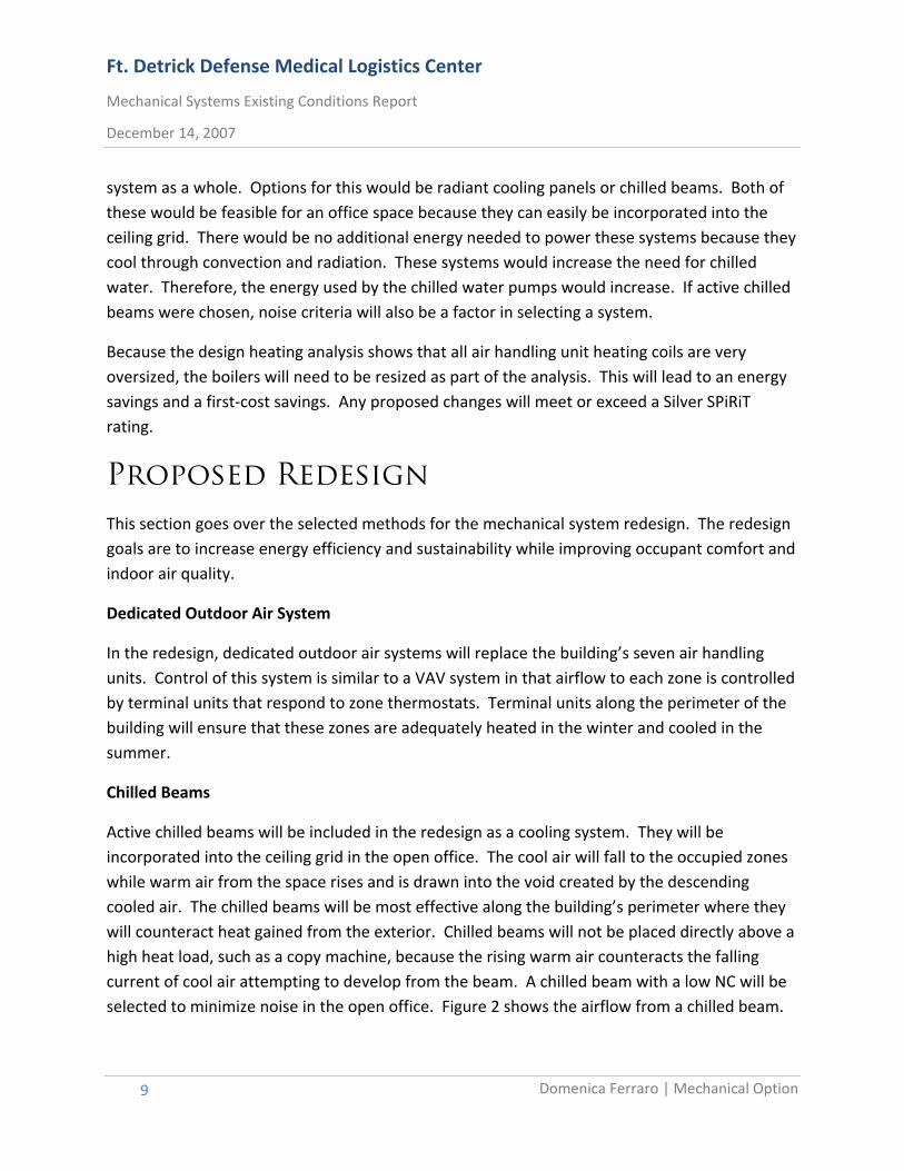
Active chilled beams will be included in the redesign as a cooling system. They will be incorporated into the ceiling grid in the open office. The cool air will fall to the occupied zones while warm air from the space rises and is drawn into the void created by the descending cooled air. The chilled beams will be most effective along the building’s perimeter where they will counteract heat gained from the exterior. Chilled beams will not be placed directly above a high heat load, such as a copy machine, because the rising warm air counteracts the falling current of cool air attempting to develop from the beam. A chilled beam with a low NC will be selected to minimize noise in the open office. Figure 2 shows the airflow from a chilled beam.
Ft. Detrick Defense Medical Logistics Center
Mechanical Systems Existing Conditions Report
January 22, 2007
Domenica Ferraro | Mechanical Option
10
Figure 2 – Flow of Air from a Chilled Beam
Indoor Air Quality Analysis
Being a military building, protection against terrorism is a requirement for design. Because a dedicated outdoor air system does not use recirculated air, any biological or chemical agents released inside the building will not be recirculated, which could reduce the amount of time it takes to purge the building of contaminants. However, since a dedicated outdoor air system supplies a smaller quantity of air than a VAV system, the amount of time it takes to purge the building of contaminants may actually increase. Also, there is essentially no carryover with proper enthalpy wheel selection and operation. A contaminant removal analysis will examine how well the building flushes out contaminates released inside and outside of the building. The analysis will compare the existing system’s effectiveness to the effectiveness of the redesigned system.
Breadth Topics
The mechanical redesign topics discussed in the previous section would change other building systems if implemented. The following sections go over the changes to the structural and electrical systems that will be analyzed.
Architectural/Site Breadth
The goal of the architectural/site breadth is to obtain SPiRiT credit 2.C2, which requires innovative use of wastewater technology. This can be done by reusing storm water or grey water for sewage conveyance or implementing an on‐site wastewater treatment system. The
Ft. Detrick Defense Medical Logistics Center
Mechanical Systems Existing Conditions Report
December 14, 2007
Domenica Ferraro | Mechanical Option
11
wastewater treatment system that will be used for this purpose will be in the form of a constructed wetland that is architecturally appealing and works well on the site.
Electrical Breadth
Implementing new mechanical systems will change the loads to the building’s central plant. This will change the overall amount of power required for the building. Because of this, the distribution panels will need resized. Also, changing equipment will require different sized wiring. The distribution panels and wiring will be resized as part of the electrical breadth. Then, a cost analysis will be done on the new panels and wiring. This will more fully analyze the cost impact of the changes to the mechanical system. Calculations will be done in Excel.
Tasks and Tools
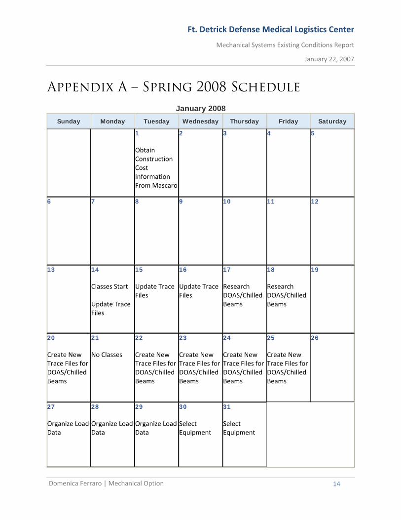
This section outlines the steps that will be taken to perform the redesign and determine the level of improvement of implementing these systems. It will also go through the computer programs and other tools that will be needed in the analysis. The goal is to complete tasks in a timely manner according to the schedule in Appendix A.
Trane Trace 700 will be used to calculate the new building loads and compare them to the current design. It will also compare energy usage and utility cost to the original. Manufacturer’s data for DOAS systems, chilled beams, and any indoor air quality equipment (if implemented) will be obtained for information on size, cost, and capacity. The floor plan will then be rearranged to show optimal location of chilled beams and DOAS equipment. It can then be determined if the size or quantity of the mechanical rooms can decrease due to the DOAS systems replacing the AHUs. After the redesign, the building’s SPiRiT (Sustainable Project Rating Tool) points will be recalculated to determine if a higher rating can be obtained.
For the structural breadth, the manual for steel construction will be used to aid in redesign. Cost analysis will be done through contacting manufacturers and consulting R.S. Means. Microsoft Excel will aid in these calculations.
Ft. Detrick Defense Medical Logistics Center
Mechanical Systems Existing Conditions Report
January 22, 2007
Domenica Ferraro | Mechanical Option
12
Conclusions
The current mechanical system design for Ft. Detrick is appropriate for its application, but it can be improved in many ways. Through implementing DOAS and chilled beams, the building’s energy consumption will decrease, and the overall satisfaction of the occupants will increase. This, along with any improvements made to indoor air quality, will raise productivity and provide a better work atmosphere for employees. These are the main goals of next semester’s redesign, but it is also hoped that the redesign will provide a valuable educational experience. With the redesign of mechanical, structural, and electrical systems, Ft. Detrick will hopefully have a better solution to the design requirements.
Preliminary Research/References
Air Balancing Company, Inc. www.airbalancingco.com. December 2, 2007.
• This site provided information, both good and bad, on the existing variable air volume system.
Dedicated Outdoor Air Systems (DOAS). http://doas‐radiant.psu.edu/. December 12, 2007.
• This site provided an overview of the operation of dedicated outdoor air systems. It also explained how DOAS improves occupant comfort. Additionally, for a military building, DOAS can prevent the spread of harmful chemicals, which is a requirement for Ft. Detrick.
Mechanical Construction Documents. Baker and Associates, Moon Township, PA. 2007.
• These documents include the engineer’s design analysis, drawings, and specifications that will be used as the base model to be redesigned for this thesis.
Schultz, Carl C. “Next Generation Cooling is Looking Up.” Engineered Systems Magazine. May 2, 2007.
• This article explains the many benefits of chilled beams. It goes over their applications, distribution, and control systems.
Ft. Detrick Defense Medical Logistics Center
Mechanical Systems Existing Conditions Report
December 14, 2007
Domenica Ferraro | Mechanical Option
13
Sustainable Design. http://aeieng.com/services/sustainable/chilledbeam.htm. December 6, 2007.
• This site explains how chilled beams work and areas appropriate for their application. The image in Figure 2 was taken from this site.
Unified Facilities Criteria. U.S. Army Corps of Engineers, Baltimore, MD. 2003.
• The UFC were used by Baker and Associates as guidelines for the design of Ft. Detrick. These guidelines outline standards for the protection of occupants in the event of a terrorist attack.
Underfloor Air Technology Home Page. http://www.cbe.berkeley.edu/underfloorair /Default.htm. December 9, 2007.
• This site offered the pros and cons of UFAD, possible layouts, and case studies for comparison.
Ft. Detrick Defense Medical Logistics Center
Mechanical Systems Existing Conditions Report
January 22, 2007
Domenica Ferraro | Mechanical Option
14
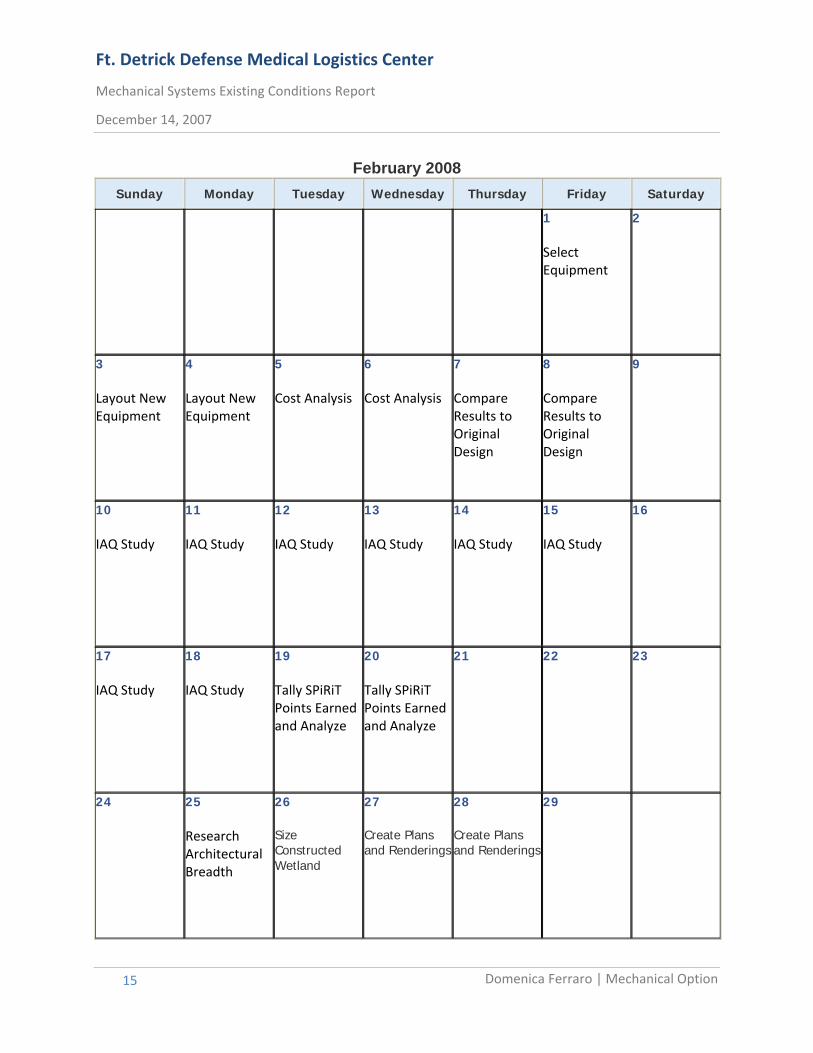
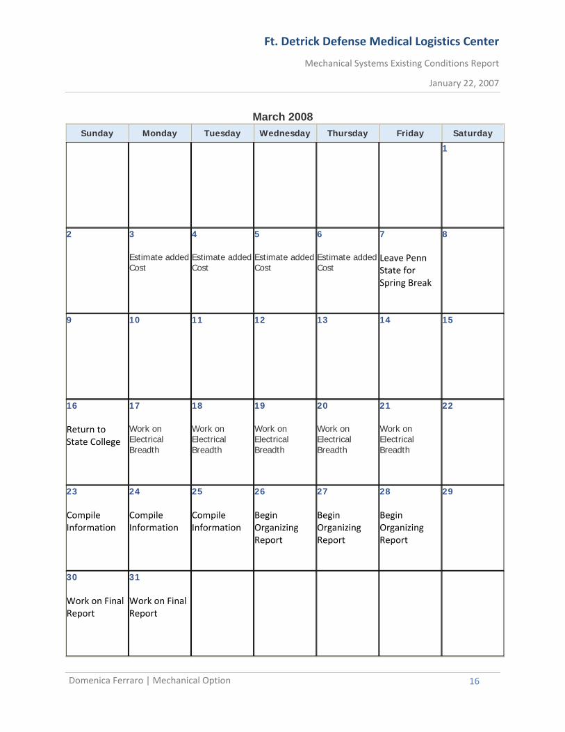
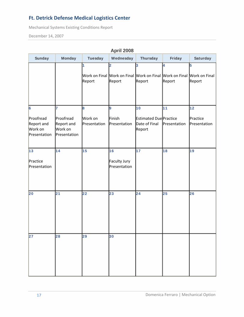
Appendix A – Spring 2008 Schedule
January 2008 Sunday Monday Tuesday Wednesday Thursday Friday Saturday
1 Obtain Construction Cost Information From Mascaro
2 3 4 5
6 7 8 9 10 11 12
13 14 Classes Start Update Trace Files
15 Update Trace Files
16 Update Trace Files
17 Research DOAS/Chilled Beams
18 Research DOAS/Chilled Beams
19
20 Create New Trace Files for DOAS/Chilled Beams
21 No Classes
22 Create New Trace Files for DOAS/Chilled Beams
23 Create New Trace Files for DOAS/Chilled Beams
24 Create New Trace Files for DOAS/Chilled Beams
25 Create New Trace Files for DOAS/Chilled Beams
26
27 Organize Load Data
28 Organize Load Data
29 Organize Load Data
30 Select Equipment
31 Select Equipment
Ft. Detrick Defense Medical Logistics Center
Mechanical Systems Existing Conditions Report
December 14, 2007
Domenica Ferraro | Mechanical Option
15
February 2008 Sunday Monday Tuesday Wednesday Thursday Friday Saturday
1 Select Equipment
2
3 Layout New Equipment
4 Layout New Equipment
5 Cost Analysis
6 Cost Analysis
7 Compare Results to Original Design
8 Compare Results to Original Design
9
10 IAQ Study
11 IAQ Study
12 IAQ Study
13 IAQ Study
14 IAQ Study
15 IAQ Study
16
17 IAQ Study
18 IAQ Study
19 Tally SPiRiT Points Earned and Analyze
20 Tally SPiRiT Points Earned and Analyze
21
22
23
24
25 Research Architectural Breadth
26 Size Constructed Wetland
27 Create Plans and Renderings
28 Create Plans and Renderings
29
Ft. Detrick Defense Medical Logistics Center
Mechanical Systems Existing Conditions Report
January 22, 2007
Domenica Ferraro | Mechanical Option
16
March 2008 Sunday Monday Tuesday Wednesday Thursday Friday Saturday
1
2
3 Estimate added Cost
4 Estimate addedCost
5 Estimate addedCost
6 Estimate addedCost
7 Leave Penn State for Spring Break
8
9 10 11 12 13 14 15
16 Return to State College
17 Work on Electrical Breadth
18 Work on Electrical Breadth
19 Work on Electrical Breadth
20 Work on Electrical Breadth
21 Work on Electrical Breadth
22
23 Compile Information
24 Compile Information
25 Compile Information
26 Begin Organizing Report
27 Begin Organizing Report
28 Begin Organizing Report
29
30 Work on Final Report
31 Work on Final Report
Ft. Detrick Defense Medical Logistics Center
Mechanical Systems Existing Conditions Report
December 14, 2007
Domenica Ferraro | Mechanical Option
17
April 2008 Sunday Monday Tuesday Wednesday Thursday Friday Saturday
1 Work on Final Report
2 Work on Final Report
3 Work on Final Report
4 Work on Final Report
5 Work on Final Report
6 Proofread Report and Work on Presentation
7 Proofread Report and Work on Presentation
8 Work on Presentation
9 Finish Presentation
10 Estimated Due Date of Final Report
11 Practice Presentation
12 Practice Presentation
13 Practice Presentation
14
15
16 Faculty Jury Presentation
17
18
19
20 21 22 23 24 25 26
27 28 29 30


![[Học Logistics] Chương trình English for Logistics - Tiếng Anh chuyên ngành logistics](https://img.pdfslide.tips/doc/110x75/55a442141a28ab51538b486d/hoc-logistics-chuong-trinh-english-for-logistics-tieng-anh-chuyen-nganh-logistics.jpg)