Embed Size (px)
Citation preview
Guide for Passenger Comfort on Ships
GUIDE FOR
PASSENGER COMFORT ON SHIPS
SEPTEMBER 2014 (Updated January 2015 – see next page)
American Bureau of Shipping Incorporated by Act of Legislature of the State of New York 1862
Copyright 2014 American Bureau of Shipping ABS Plaza 16855 Northchase Drive Houston, TX 77060 USA
Updates
January 2015 consolidation includes: • September 2014 version plus Corrigenda/Editorials
ABS GUIDE FOR PASSENGER COMFORT ON SHIPS . 2014 iii
F o r e w o r d
Foreword ABS has produced this Guide for Passenger Comfort on Ships in order to provide a single source for comfort criteria suitable for passenger ships. ABS has established objective assessment criteria and measurement methodologies for comfort based on current research and standards relating to human psychological and physiological responses. This Guide may be applied to passenger vessels carrying more than twelve (12) passengers used for such purposes as commuting, traveling, vacationing, and recreating. This includes cruise ships and ferries (conventional and high-speed craft).
This Guide provides the assessment criteria and describes the measurement methodology for obtaining a Comfort notation. It is intended for use by vessel Owners or companies requesting the optional notations of Comfort (COMF) or Comfort Plus (COMF+).
For the Comfort (COMF) notation, this Guide focuses on four (4) categories of comfort criteria that can be controlled, measured, and assessed in passenger spaces of vessels. These categories are: whole-body vibration, noise, indoor climate, and lighting.
For the Comfort Plus (COMF+) notation, this Guide invokes more stringent whole-body vibration criteria aimed at the assessment of passenger comfort and potential motion sickness.
This Guide, originally published in December 2001, has undergone significant revision. Key revision areas include changes to the whole-body vibration (WBV) measurement and evaluation methodology and criteria, changes to the ambient lighting methodology and criteria, changes to the noise criteria and removal of the accommodation area criteria. These revisions are due to several factors, including:
1. Input from industry (i.e., Owners, designers, and construction yards)
2 Revisions to standards referenced in this Guide
3. Revised statutory regulations
4. Changes in current design practices and principles
This Guide becomes effective on the first day of the month of publication.
Users are advised to check periodically on the ABS website www.eagle.org to verify that this version of this Guide is the most current.
We welcome your feedback. Comments or suggestions can be sent electronically by email to [email protected].
iv ABS GUIDE FOR PASSENGER COMFORT ON SHIPS . 2014
T a b l e o f C o n t e n t s
GUIDE FOR
PASSENGER COMFORT ON SHIPS CONTENTS SECTION 1 General .................................................................................................... 1
1 Introduction ......................................................................................... 1 2 Application ........................................................................................... 1 3 Scope .................................................................................................. 1 4 Terminology ........................................................................................ 2 5 Associated Documentation ................................................................. 2 6 Notation ............................................................................................... 2 7 Data and Plans to be Submitted ......................................................... 3
7.1 General ............................................................................................ 3 7.2 Ambient Environment ...................................................................... 3
8 Process for Obtaining a Notation ........................................................ 4 8.1 Ambient Environment ...................................................................... 4 8.2 Results ............................................................................................. 4
9 Initial Requirements ............................................................................ 6 10 Surveys after Construction .................................................................. 6
10.1 Annual Surveys ............................................................................... 6 10.2 Special Periodical Surveys .............................................................. 6 10.3 Requirements for Vessel Alterations ................................................ 8
11 Alternatives ......................................................................................... 8 11.1 General ............................................................................................ 8 11.2 National Regulations ........................................................................ 8 11.3 Departures from Criteria .................................................................. 8
FIGURE 1 Process for Obtaining a Comfort Notation ................................ 5
SECTION 2 Whole-body Vibration ............................................................................ 9
1 Background ......................................................................................... 9 2 Scope .................................................................................................. 9 3 Terminology ........................................................................................ 9 4 Associated Documentation ............................................................... 10 5 Criteria ............................................................................................... 11 6 Test Plan ........................................................................................... 12
6.1 Documentation .............................................................................. 12 6.2 Test Personnel .............................................................................. 12 6.3 Test Conditions .............................................................................. 12
ABS GUIDE FOR PASSENGER COMFORT ON SHIPS . 2014 v
6.4 Measurement Locations ................................................................ 12 6.5 Data Acquisition and Instruments .................................................. 13 6.6 Data Analysis ................................................................................ 13 6.7 Test Schedule ............................................................................... 13
7 Test Requirements ............................................................................ 13 7.1 General.......................................................................................... 13 7.2 Data Acquisition and Instruments .................................................. 13 7.3 Test Conditions ............................................................................. 15 7.4 Measurement Locations ................................................................ 15
8 Test Report ....................................................................................... 17 8.1 Test Details ................................................................................... 17 8.2 Transducer Measurement Positions .............................................. 17 8.3 Measurement Equipment Details .................................................. 17 8.4 Results .......................................................................................... 17 8.5 Deviations ...................................................................................... 18 8.6 Surveyor Witnessing Documentation ............................................ 18
9 Results .............................................................................................. 18 TABLE 1 Maximum Root-Mean-Square Acceleration Level .................. 11 TABLE 2 Distribution of Transducer Positions within Spaces ................ 16 FIGURE 1 Measurement Axes ................................................................. 12 FIGURE 2 Process for the Measurement and Analysis of Whole-body
Vibration .................................................................................. 14 SECTION 3 Noise ..................................................................................................... 19
1 Background ....................................................................................... 19 2 Scope ................................................................................................ 19 3 Terminology ...................................................................................... 19 4 Associated Documentation ............................................................... 19 5 Criteria ............................................................................................... 20
5.1 Equivalent Continuous A-weighted Sound Pressure Level............ 20 5.2 Acoustic Insulation ........................................................................ 20
6 Test Plan ........................................................................................... 20 6.1 Documentation .............................................................................. 21 6.2 Test Personnel .............................................................................. 21 6.3 Test Conditions ............................................................................. 21 6.4 Measurement Locations ................................................................ 21 6.5 Data Acquisition and Instruments .................................................. 21 6.6 Data Analysis ................................................................................ 21 6.7 Test Schedule ............................................................................... 21
7 Test Requirements ............................................................................ 21 7.1 General.......................................................................................... 21 7.2 Data Acquisition and Instruments .................................................. 21 7.3 Test Conditions ............................................................................. 21 7.4 Measurement Locations ................................................................ 22 7.5 Measurement Procedures and Recorded Results ......................... 23
vi ABS GUIDE FOR PASSENGER COMFORT ON SHIPS . 2014
8 Test Report ....................................................................................... 23 8.1 Test Details .................................................................................... 24 8.2 Measurement Positions ................................................................. 24 8.3 Measurement Equipment Details ................................................... 24 8.4 Results ........................................................................................... 24 8.5 Deviations ...................................................................................... 24 8.6 Surveyor Witnessing Documentation ............................................. 24
9 Results .............................................................................................. 25 TABLE 1 Noise Criteria .......................................................................... 20
SECTION 4 Indoor Climate ...................................................................................... 26
1 Background ....................................................................................... 26 2 Scope ................................................................................................ 26 3 Terminology ...................................................................................... 26 4 Associated Documentation ............................................................... 27 5 Criteria ............................................................................................... 27
5.1 Air Temperature ............................................................................. 27 5.2 Relative Humidity ........................................................................... 27 5.3 Enclosed Space Vertical Gradient ................................................. 28 5.4 Air Velocity ..................................................................................... 28 5.5 Passenger Cabin Area Horizontal Gradient ................................... 28 5.6 Air Exchange Rate ......................................................................... 28 5.7 Summary ....................................................................................... 28
6 Test Plan ........................................................................................... 28 6.1 Documentation .............................................................................. 28 6.2 Test Personnel .............................................................................. 29 6.3 Test Conditions .............................................................................. 29 6.4 Measurement Locations ................................................................ 29 6.5 Data Acquisition and Instruments .................................................. 29 6.6 Data Analysis ................................................................................. 29 6.7 Test Schedule ................................................................................ 29
7 Test Requirements ............................................................................ 29 7.1 General .......................................................................................... 29 7.2 Data Acquisition and Instruments .................................................. 29 7.3 Test Conditions .............................................................................. 30 7.4 Measurement Locations ................................................................ 30
8 Test Report ....................................................................................... 31 8.1 Test Details .................................................................................... 31 8.2 Transducer Measurement Positions .............................................. 32 8.3 Measurement Equipment Details ................................................... 32 8.4 Results ........................................................................................... 32 8.5 Deviations ...................................................................................... 32 8.6 Surveyor Witnessing Documentation ............................................. 32
9 Results .............................................................................................. 32 TABLE 1 Summary of Indoor Climate Requirements ............................. 28
ABS GUIDE FOR PASSENGER COMFORT ON SHIPS . 2014 vii
SECTION 5 Lighting ................................................................................................. 33 1 Background ....................................................................................... 33 2 Scope ................................................................................................ 33 3 Terminology ...................................................................................... 33 4 Associated Documentation ............................................................... 34 5 Criteria ............................................................................................... 34 6 Test Plan ........................................................................................... 36
6.1 Documentation .............................................................................. 36 6.2 Test Personnel .............................................................................. 36 6.3 Test Conditions ............................................................................. 36 6.4 Measurement Locations ................................................................ 36 6.5 Data Acquisition and Instruments .................................................. 36 6.6 Data Analysis ................................................................................ 36 6.7 Test Schedule ............................................................................... 36
7 Test Requirements ............................................................................ 36 7.1 General.......................................................................................... 36 7.2 Data Acquisition and Instruments .................................................. 36 7.3 Test Conditions ............................................................................. 37 7.4 Measurement Locations ................................................................ 37
8 Test Report ....................................................................................... 39 8.1 Test Details ................................................................................... 39 8.2 Measurement Positions ................................................................. 39 8.3 Measurement Equipment Details .................................................. 39 8.4 Results .......................................................................................... 40 8.5 Deviations ...................................................................................... 40 8.6 Surveyor Witnessing Documentation ............................................ 40
9 Results .............................................................................................. 40 TABLE 1 Lighting Criteria for Passenger Spaces .................................. 35 TABLE 2 Distribution of Measurement Positions within Spaces ............ 39
APPENDIX 1 References ............................................................................................ 41
1 General References .......................................................................... 41 2 Whole-body Vibration References .................................................... 41 3 Noise References ............................................................................. 41 4 Indoor Climate References ............................................................... 42 5 Lighting References .......................................................................... 42
APPENDIX 2 Procedural Requirements for ABS Recognized Ambient
Environmental Testing Specialists ..................................................... 43 1 Terminology ...................................................................................... 43 2 Objective ........................................................................................... 43 3 Application ........................................................................................ 43 4 Procedure for Approval and Certification .......................................... 44
4.1 Documentation Requirements ....................................................... 44 4.2 General Requirements .................................................................. 44
viii ABS GUIDE FOR PASSENGER COMFORT ON SHIPS . 2014
4.3 Auditing of the Testing Specialist ................................................... 45 4.4 Certification .................................................................................... 45 4.5 Quality Assurance System ............................................................. 45 4.6 Testing Specialist Relations with the Test Equipment
Manufacturer ................................................................................. 46 5 Certificate of Approval ....................................................................... 46
5.1 Renewal ......................................................................................... 46 6 Alterations ......................................................................................... 46 7 Cancellation of Approval ................................................................... 46 8 Detailed Requirements by Ambient Environmental Aspect .............. 47
8.1 Whole-body Vibration .................................................................... 47 8.2 Noise ............................................................................................. 48 8.3 Indoor Climate ............................................................................... 49 8.4 Lighting .......................................................................................... 50
APPENDIX 3 Acronyms and Abbreviations .............................................................. 51 APPENDIX 4 Associated Documentation ................................................................. 53
ABS GUIDE FOR PASSENGER COMFORT ON SHIPS . 2014 1
S e c t i o n 1 : G e n e r a l
S E C T I O N 1 General
1 Introduction ABS recognizes the positive impact that suitable comfort criteria and design practices may have on the comfort, safety, and overall well-being of passengers. The ABS Guide for Passenger Comfort on Ships has been developed with the objective of improving the comfort of the passengers on board passenger vessels. These comfort criteria have been chosen to provide a means to increase the comfort, enjoyment, and satisfaction of passengers.
2 Application ABS has produced this Guide for Passenger Comfort on Ships in order to provide a single source for comfort criteria suitable for passenger ships. This Guide may be applied to passenger vessels carrying more than twelve (12) passengers used for such purposes as commuting, traveling, vacationing and recreating. This includes cruise ships and ferries (conventional and high-speed craft).
This Guide is applicable to new and existing passenger vessels for which an optional Comfort (COMF) or a Comfort Plus (COMF+) notation has been requested. The comfort criteria are a measure of the acceptability of passenger accommodation areas and their associated ambient environmental criteria.
3 Scope The Guide focuses on four (4) comfort aspects of passenger ship design and layout that can be controlled, measured, and assessed.
The ambient environmental aspects of comfort pertain to the environment that the passengers are exposed to on board vessels. Specifically, this Guide provides criteria, limits and measurement methodologies for the following:
i) Whole-body Vibration
ii) Noise
iii) Indoor Climate
iv) Lighting.
The criteria provided in this Guide are based on currently available research data and standards for the purpose of providing a base level of passenger comfort. This Guide does not specifically address passenger safety since safety is comprehensively covered by the International Maritime Organization (IMO), Flag Administrations, Class Society Rules and Port States. However, where appropriate, compliance with this Guide may warrant an enhancement in some safety systems on board the vessel.
The various criteria, test conditions, measurement locations, test methods and instruments required by this Guide may differ from the more rigorous and scientific methods reported and practiced elsewhere by the scientific community. They were, however, selected with the aim of providing a practical Guide that could be applied internationally by ABS and vessel Owners/shipbuilders with reliability and acceptable validity.
While producing this Guide, ABS has taken a practical approach to measurements, test personnel (Testing Specialists) and test equipment.
Section 1 General
2 ABS GUIDE FOR PASSENGER COMFORT ON SHIPS . 2014
4 Terminology Accommodation Areas: Vessel areas where the primary purpose is to rest and recreate. Passenger accommodation spaces include cabins, staterooms, dining areas, recreation rooms, medical facilities and other public spaces. For the purposes of this Guide, accommodation areas are primarily restricted to the spaces passengers would normally use on board vessels.
Ambient Environment: Ambient environment refers to the environmental conditions that passengers are exposed to during periods of transit, leisure, or rest. Specifically, this Guide provides criteria and limits for whole-body vibration, noise, indoor climate and lighting.
Comfort: The acceptability of the conditions of a vessel as determined by its vibration, noise, thermal, indoor climate and lighting qualities as well as its physical and spatial characteristics, according to prevailing research and standards for human comfort.
Occupied Passenger Spaces: For the purposes of this Guide, any space where passengers may be present for twenty (20) minutes or longer at one time for transit, rest or leisure purposes.
Passenger: A passenger is every person other than the Master and the members of the crew or other persons employed or engaged in any capacity on board a vessel for the business of that vessel.
Passenger Vessel: A vessel whose primary purpose is to carry more than twelve (12) passengers for transportation or recreational purposes. This includes cruise ships and ferries (conventional and high-speed craft).
Recreation and Public Spaces: Those portions of the passenger spaces that are used for halls, dining rooms, lounges, theaters, and similar permanently enclosed spaces.
Shall: Expresses a provision that is mandatory.
Test Plan: Document containing the requisite information regarding vessel design and layout, test personnel, test conditions, measurement locations, data acquisition, instruments, data analysis and test schedule necessary for verifying the measurements for the ambient environmental aspects of comfort.
Test Report: Document containing the actual testing information from the Ambient Environmental tests including details of the testing conditions, measurement locations, measurement equipment, and the results of the data collected and analyzed.
Testing Specialists: Specialized test personnel who must meet the requirements of Appendix 2, “Procedural Requirements for ABS Recognized Ambient Environmental Testing Specialists”.
5 Associated Documentation • Appendix 2, “Procedural Requirements for ABS Recognized Ambient Environmental Testing Specialists”
6 Notation At the Owner’s or shipyard’s request, a vessel complying with the minimum criteria for the ambient environmental aspects (i.e., whole-body vibration, noise, indoor climate, and lighting) provided in this Guide may be assigned a notation of COMF.
A vessel complying with the more stringent criteria with respect to whole-body vibration (including motion sickness) may be distinguished in the Record by the notation COMF+. A summary of the differences among each of these notations is presented below.
Section 1 General
ABS GUIDE FOR PASSENGER COMFORT ON SHIPS . 2014 3
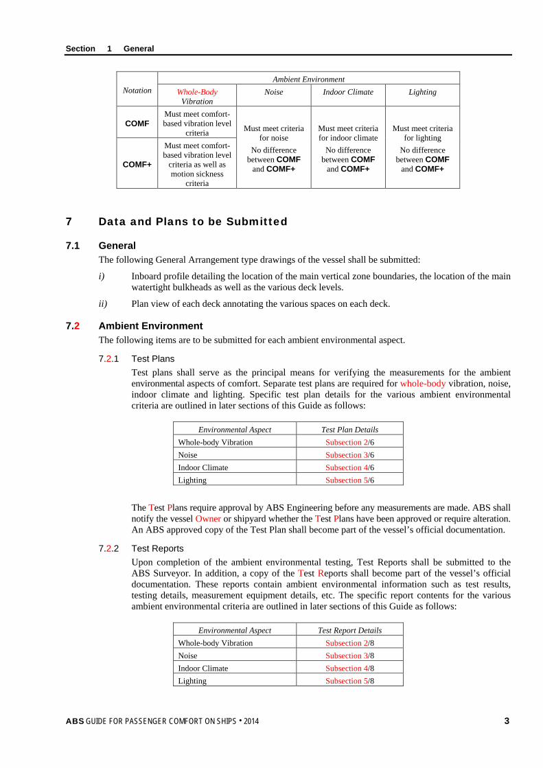
Notation Ambient Environment
Whole-Body Vibration
Noise Indoor Climate Lighting
COMF Must meet comfort-based vibration level
criteria Must meet criteria for noise
No difference between COMF
and COMF+
Must meet criteria for indoor climate
No difference between COMF
and COMF+
Must meet criteria for lighting
No difference between COMF
and COMF+ COMF+
Must meet comfort-based vibration level
criteria as well as motion sickness
criteria
7 Data and Plans to be Submitted
7.1 General The following General Arrangement type drawings of the vessel shall be submitted:
i) Inboard profile detailing the location of the main vertical zone boundaries, the location of the main watertight bulkheads as well as the various deck levels.
ii) Plan view of each deck annotating the various spaces on each deck.
7.2 Ambient Environment The following items are to be submitted for each ambient environmental aspect.
7.2.1 Test Plans Test plans shall serve as the principal means for verifying the measurements for the ambient environmental aspects of comfort. Separate test plans are required for whole-body vibration, noise, indoor climate and lighting. Specific test plan details for the various ambient environmental criteria are outlined in later sections of this Guide as follows:
Environmental Aspect Test Plan Details Whole-body Vibration Subsection 2/6 Noise Subsection 3/6 Indoor Climate Subsection 4/6 Lighting Subsection 5/6
The Test Plans require approval by ABS Engineering before any measurements are made. ABS shall notify the vessel Owner or shipyard whether the Test Plans have been approved or require alteration. An ABS approved copy of the Test Plan shall become part of the vessel’s official documentation.
7.2.2 Test Reports Upon completion of the ambient environmental testing, Test Reports shall be submitted to the ABS Surveyor. In addition, a copy of the Test Reports shall become part of the vessel’s official documentation. These reports contain ambient environmental information such as test results, testing details, measurement equipment details, etc. The specific report contents for the various ambient environmental criteria are outlined in later sections of this Guide as follows:
Environmental Aspect Test Report Details Whole-body Vibration Subsection 2/8 Noise Subsection 3/8 Indoor Climate Subsection 4/8 Lighting Subsection 5/8
Section 1 General
4 ABS GUIDE FOR PASSENGER COMFORT ON SHIPS . 2014
8 Process for Obtaining a Notation
Prior to scheduling ambient environmental testing activities, the vessel Owner or shipyard shall certify the operational status of the vessel as being fully operational and/or inclusive of all equipment and furnishings. If the vessel is not fully operational, a complete listing of deficiencies of areas, components, equipment, etc., shall be submitted to ABS for review.
ABS shall then make a determination and notify the vessel Owner or shipyard as to whether ambient environmental testing can commence. The intent is to align sea trials/activities with the ambient environmental testing so that all testing is completed during this time.
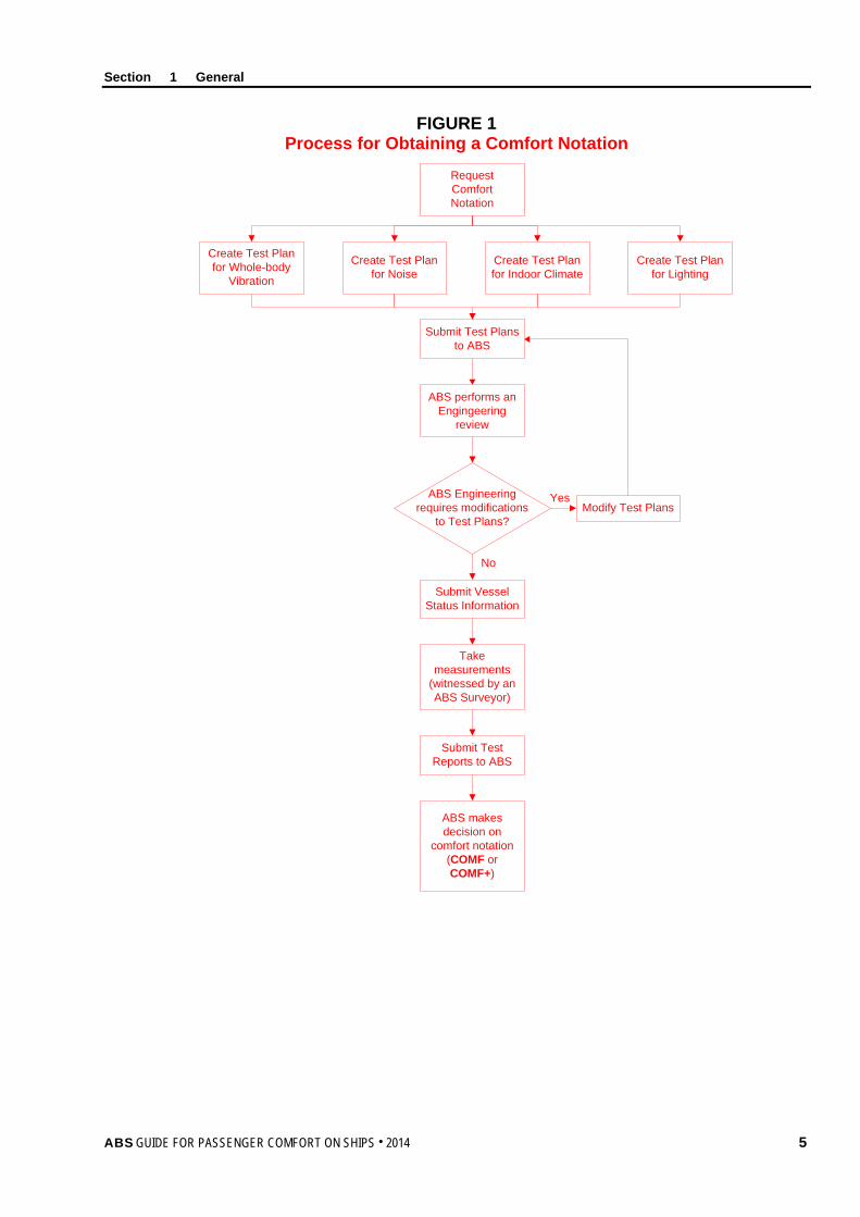
Section 1, Figure 1, “Process for Obtaining a Comfort Notation”, charts the process for obtaining a COMF or COMF+ notation. The following paragraphs briefly describe the notation process.
8.1 Ambient Environment Ambient environmental test plans for whole-body vibration, noise, indoor climate and lighting shall be prepared and submitted to ABS.
The Test Plans shall serve as a primary vehicle for verifying the measurement locations and measurement process, as well as specifying the Testing Specialist who will perform the ambient environmental testing.
Testing, inspections and data collection shall be performed by the Testing Specialists and witnessed by an ABS Surveyor. Test Reports for ambient environmental testing shall be prepared by the Testing Specialists and submitted to the ABS Surveyor for review.
8.2 Results The ABS Surveyor verification measurements and ambient environmental Test Reports shall be reviewed by the ABS Surveyor for determination of notation confirmation.
Section 1 General
ABS GUIDE FOR PASSENGER COMFORT ON SHIPS . 2014 5
FIGURE 1 Process for Obtaining a Comfort Notation
Request Comfort Notation
Create Test Plan for Lighting
Create Test Plan for Indoor Climate
Create Test Plan for Noise
Create Test Plan for Whole-body
Vibration
Submit Test Plans to ABS
ABS makes decision on
comfort notation (COMF or COMF+)
ABS performs an Engingeering
review
ABS Engineering requires modifications
to Test Plans?Modify Test Plans
Yes
No
Submit Vessel Status Information
Take measurements
(witnessed by an ABS Surveyor)
Submit Test Reports to ABS
Section 1 General
6 ABS GUIDE FOR PASSENGER COMFORT ON SHIPS . 2014
9 Initial Requirements The initial process for obtaining any passenger ship Comfort notation shall comprise ambient environmental testing and ABS Surveyor verifications. Testing shall be in accordance with the submitted Test Plans reviewed and approved by ABS Engineering in advance of the testing. Testing shall be witnessed by an ABS Surveyor. If the criteria specified in this Guide have been met, then the appropriate notation may be confirmed.
10 Surveys after Construction It is intended that all surveys after construction are to be aligned with Classification Surveys. Harmonization of surveys is to be carried out at the first available opportunity.
10.1 Annual Surveys In order to maintain the COMF or COMF+ notation, an Annual Survey shall be made within three (3) months before or after each annual anniversary date of the crediting of the Initial Survey or the previous Special Periodical Survey. The following information shall be reviewed by the attending ABS Surveyor for issues that could affect the Comfort notation:
i) Collision and grounding reports since previous Initial, Annual or Special Periodical Survey
ii) Fire, repair, and damage reports since previous Initial, Annual or Special Periodical Survey
iii) A list of all structural or mechanical modifications to the vessel since previous Initial, Annual or Special Periodical Survey
During the attending ABS Surveyor’s review of the submitted information, a determination will be made as to whether changes or alterations have taken place that could affect the Comfort notation. As a result, the vessel may be subject to the review, ambient environmental testing and inspection requirements of this Guide.
10.2 Special Periodical Surveys In order to maintain the COMF or COMF+ notation, a Special Periodical Survey shall be completed within five (5) years after the date of build or after the crediting date of the previous Special Periodical Survey. A Special Periodical Survey will be credited as of the completion date of the survey but not later than five (5) years from date of build or from the date recorded for the previous Special Periodical Survey. If the Special Periodical Survey is completed within three (3) months prior to the due date, the Special Periodical Survey will be credited to agree with the effective due date. The Special Periodical Survey may be commenced fifteen (15) months prior to the due date and be continued with completion by the due date.
10.2.1 Survey Requirements The Survey shall comprise ABS Surveyor verifications and ambient environmental testing. The Survey will cover all four (4) Comfort aspects.
The following shall be submitted to ABS three (3) months prior to carrying out the ambient environmental testing:
i) Fire, repair, or damage reports since previous Annual Survey
ii) A list of all structural or mechanical modifications to the vessel since previous Annual Survey
iii) Drawings//arrangements of passenger spaces, affected by alterations
iv) Copy of approved Initial Test Plans and Test Reports
v) Test Plans and Test Reports resulting from Annual Surveys
vi) Proposed Special Periodical Survey Test Plans for the current survey.
vii) Previous Special Periodical Survey Test Plans and reports, if applicable.
Section 1 General
ABS GUIDE FOR PASSENGER COMFORT ON SHIPS . 2014 7
The Special Periodical Survey data submittal serves two purposes. The first purpose is to provide a history of ambient environmental testing, as well as the Special Periodical Survey ambient environmental Test Plans for review and approval. The second is to allow scheduling of measurement verifications and ambient environmental testing.
A Special Periodical Survey Test Plan for each ambient environmental aspect of Comfort shall be submitted in accordance with the criteria stated below. The approved Initial Test Plans should be used as a basis for creating the Special Periodical Survey Test Plans.
For creation of the Special Periodical Survey Test Plans, Subsection 6, “Test Plan” and Subsection 7, “Test Requirements” of this Guide specify the requirements for each ambient environmental aspect (i.e., 3/6, 3/7, 4/6, 4/7, etc.). For specifying measurement locations for the Special Periodical Survey Test Plans, the following changes to 7.4.1, “Selection of Spaces where Measurements are to be Conducted”, of each ambient environmental aspect of Comfort shall be followed:
i) Measurements shall be taken in all areas affected by vessel alterations. Measurements are limited to the ambient environmental aspect affected by the alteration. For example, structural changes would require both whole-body vibration and noise measurements. Structural changes do not necessarily require indoor climate or lighting measurements. Changes to luminaires require lighting measurements but not whole-body vibration, noise, or indoor climate measurements.
ii) For whole-body vibration, additional measurements shall be taken in passenger cabins and staterooms throughout the vessel. For vessels with fewer than one hundred (100) passenger cabins and staterooms, ten (10) percent of cabins and staterooms shall be measured.
For vessels with one hundred (100) or more passenger cabins and staterooms, apply the following:
• In the forward one-third (1/3) of the vessel, seven (7) percent or 1 in 15 of cabins and staterooms shall be measured
• In the midsection (center 1/3) of the vessel, five (5) percent or 1 in 25 of cabins and staterooms shall be measured
• In the aft one-third (1/3) of the vessel, ten (10) percent 1 in 10 of the cabins and staterooms shall be measured.
Within each one-third (1/3) section of the vessel, measurement locations shall be distributed throughout the length of each section and on each deck.
iii) For all ambient environmental aspects, measurements shall be taken in all worst case or problem area locations based on the requirements set forth in 7.4.1, “Selection of Spaces where Measurements are to be Conducted”, of the appropriate section of this Guide. [For example, worst case for whole-body vibration is described in 2/7.4.1i)].
iv) For all ambient environmental aspects, measurements shall be taken in twenty-five (25) percent of passenger cabins identified in the initial Test Plans. The cabin locations must be representative of locations port, starboard, fore, amidships, and aft. Any worst case locations can be considered part of the representative sample for passenger cabins, if applicable.
v) For all ambient environmental aspects, measurements shall be taken where a single instance of one (1) type of a passenger space exists within the vessel (e.g., dining room, gymnasium, library, etc.). The worst case locations can be considered part of the single instance representative sample, if applicable.
vi) Where multiple instances of the same type space exist, a representative sample of at least twenty-five (25) percent of each type shall be selected for measurement for all ambient environmental aspects. The worst case locations are to be considered part of the representative sample, if applicable.
vii) For the COMF+ notation, vibration measurement locations relating to motion sickness shall be selected in accordance with the applicable criteria in 2/7.4.1, “Selection of Spaces where Measurements are to be Conducted”.
Section 1 General
8 ABS GUIDE FOR PASSENGER COMFORT ON SHIPS . 2014
viii) For lighting, select a sample of at least ten (10) percent of spaces where passengers are involved in recreational activities (e.g., dining rooms, lounges, theater, gymnasium, etc.) for measurement.
Where a number of cabins and sanitary spaces are identical in configuration in terms of lighting systems, surface treatments, geometry, furnishings and equipment layout, only two (2) of the spaces shall be selected to determine whether the lighting requirements are met. A sample of at least fifteen (15) percent of the remaining spaces shall be visually inspected.
The worst case locations can be considered part of these lighting representative samples, if applicable.
For all ambient environmental conditions, visual/walkthrough inspections shall be conducted in accordance with 7.4.2 of the appropriate Section of this Guide.
10.3 Requirements for Vessel Alterations No alterations which affect or may affect the Comfort notation awarded, including alterations to the structure, machinery, electrical systems, piping, furnishings or lighting systems, are to be made to the vessel unless plans of the proposed alterations are submitted to and approved by ABS before the work of alteration is commenced. If ABS determines that the alteration will affect the Comfort notation, the altered vessel may be subject to the review, verification, and ambient environmental testing requirements of this Guide.
11 Alternatives
11.1 General ABS will consider alternative arrangements, criteria and procedures, which can be shown to meet the intent of the criteria directly cited or referred to in this Guide. The demonstration of an alternative’s acceptability can be made through either the presentation of satisfactory service experience or systematic analysis based on valid engineering principles.
11.2 National Regulations ABS will consider for its acceptance alternative arrangements and details, which can be shown to comply with standards recognized in the country (flag State) in which the vessel is registered or built, provided they are not deemed less effective.
11.3 Departures from Criteria The criteria contained in this Guide are envisioned to apply to vessels that are engaged in the usual trades and services expected of such vessels, within the scope of the following:
• ABS Rules for Building and Classing Steel Vessels
• ABS Rules for Building and Classing High-Speed Craft
• ABS Rules for Materials and Welding
• ABS Rules for Building and Classing Steel Vessels for Service on Rivers and Intracoastal Waterways
• ABS Rules for Materials and Welding: Aluminum and Fiber Reinforced Plastics
It is recognized that unusual or unforeseen conditions may lead to a case where one or more of the parameters of interest in granting a notation may temporarily fall outside the range of acceptability.
When a departure from criteria is identified, during either the notation’s initial issuance or reconfirmation process, it shall be reviewed by ABS in consultation with the Owner. When the ambient environmental test results contain departures from the stated criteria, these will be subject to special consideration upon the receipt of details about the departure. Depending on the degree and consequences of the departure, the shipyard or Owner may be required to provide an assessment and remediation plan to obtain or maintain the notation. Failure to complete the agreed remediation by the due date will lead to withdrawal of the notation.
ABS GUIDE FOR PASSENGER COMFORT ON SHIPS . 2014 9
S e c t i o n 2 : W h o l e - b o d y V i b r a t i o n
S E C T I O N 2 Whole-body Vibration
1 Background Transport in vessels, whether conventional or high-speed, imposes a series of generally low-frequency mechanical vibrations, as well as single-impulse shock loads on the human body.
Low-frequency vibrations are also imposed by vessel motions, which are produced by the various sea states in conjunction with vessel speed. These motions can result in motion sickness, body instability, fatigue, discomfort, and increased health risk aggravated by shock loads induced by vessel slamming. Vessel slamming may be caused by dynamic impact loads being exerted on the vessel’s bottom or bow flare due to vessel size, speed, and wave conditions.
Higher frequency vibration influencing comfort is often associated with rotating machinery. The imposition of higher frequency vibrations (about 1 to 80 Hz) induces corresponding motions and forces within the human body, creating discomfort and possibly resulting in degraded health (Griffin, 1990).
2 Scope This Section provides the criteria and methods for assessing whole-body vibration relating to passenger comfort onboard vessels. The criteria were selected to limit potential vibration-related interference with passenger activities and to improve passenger comfort.
Consideration of the vibration loads imposed on the body is restricted to motions transmitted from surrounding structures to the entire human body through the feet of a standing person in the frequency range 1 to 80 Hertz (Hz). Motions transmitted to the body of a seated or recumbent person have been omitted from this Guide. Due to the provision of resilient or non-rigid surfaces on seats and beds, these surfaces will generally attenuate the transfer of vibration to levels that are lower than those experienced when standing. The motions transmitted through the feet are expected to be the highest vibration levels to which passengers will be exposed and more prone to motion sickness.
Whole-body vibration limits defined in this Section are based on currently available standards. Compliance with this Section is a prerequisite for the Comfort (COMF) or Comfort Plus (COMF+) notation confirmation.
3 Terminology Acceleration: The rate of change of velocity over time (i.e., meters-per-second squared, m/s2).
Exposure Action Value: The value of vibration/repetitive shock above which controlling the whole-body vibration exposure to humans is recommended.
Exposure Limit Value: A value of vibration/repetitive shock above which humans should not be exposed.
Frequency: The number of complete cycles of a periodic process occurring per unit time. Frequency is expressed in Hertz (Hz) which corresponds to the number of cycles observed-per-second.
Frequency Weighting: A transfer function used to modify a signal according to a required dependence on vibration frequency.
• In human response to vibration, various frequency weightings have been defined in order to reflect known or hypothesized relationships between vibration frequency and human responses.
• The frequency weightings used to evaluate whole-body vibration in this Guide is Wm (whole-body) for all three axes (x, y, and z), in accordance with ISO 6954.
Section 2 Whole-body Vibration
10 ABS GUIDE FOR PASSENGER COMFORT ON SHIPS . 2014
Motion Sickness: Various undesirable effects including sweating, nausea and vomiting caused by low-frequency (normally less than 0.5 Hz) oscillation in the vertical z-axis of the human body, primarily in the standing and sitting postures.
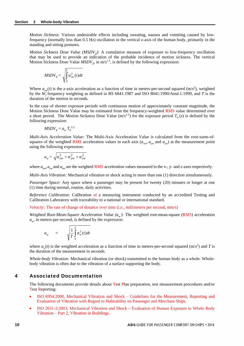
Motion Sickness Dose Value (MSDVZ): A cumulative measure of exposure to low-frequency oscillation that may be used to provide an indication of the probable incidence of motion sickness. The vertical Motion Sickness Dose Value MSDVZ, in m/s1.5, is defined by the following expression:
MSDVZ = ∫T
zw dtta0
2 )(
Where azw(t) is the z-axis acceleration as a function of time in meters-per-second squared (m/s2), weighted by the Wf frequency weighting as defined in BS 6841:1987 and ISO 8041:1990/Amd.1:1999, and T is the duration of the motion in seconds.
In the case of shorter exposure periods with continuous motion of approximately constant magnitude, the Motion Sickness Dose Value may be estimated from the frequency-weighted RMS value determined over a short period. The Motion Sickness Dose Value (m/s1.5) for the exposure period T0 (s) is defined by the following expression:
MSDVZ = aw T01/2
Multi-Axis Acceleration Value: The Multi-Axis Acceleration Value is calculated from the root-sums-of-squares of the weighted RMS acceleration values in each axis (axw, ayw and azw) at the measurement point using the following expression:
aw = 222zwywxw aaa ++
where axw, ayw and azw are the weighted RMS acceleration values measured in the x-, y- and z-axes respectively.
Multi-Axis Vibration: Mechanical vibration or shock acting in more than one (1) direction simultaneously.
Passenger Space: Any space where a passenger may be present for twenty (20) minutes or longer at one (1) time during normal, routine, daily activities.
Reference Calibration: Calibration of a measuring instrument conducted by an accredited Testing and Calibration Laboratory with traceability to a national or international standard.
Velocity: The rate of change of distance over time (i.e., millimeters per second, mm/s)
Weighted Root-Mean-Square Acceleration Value (aw ): The weighted root-mean-square (RMS) acceleration aw, in meters-per-second, is defined by the expression:
aw = dttaT
T
w )(1
0
2∫
where aw(t) is the weighted acceleration as a function of time in meters-per-second squared (m/s2) and T is the duration of the measurement in seconds.
Whole-body Vibration: Mechanical vibration (or shock) transmitted to the human body as a whole. Whole-body vibration is often due to the vibration of a surface supporting the body.
4 Associated Documentation The following documents provide details about Test Plan preparation, test measurement procedures and/or Test Reporting:
• ISO 6954:2000, Mechanical Vibration and Shock – Guidelines for the Measurement, Reporting and Evaluation of Vibration with Regard to Habitability on Passenger and Merchant Ships.
• ISO 2631-2:2003, Mechanical Vibration and Shock – Evaluation of Human Exposure to Whole Body Vibration – Part 2, Vibration in Buildings.
Section 2 Whole-body Vibration
ABS GUIDE FOR PASSENGER COMFORT ON SHIPS . 2014 11
• ISO 8041:2005, Human response to vibration – Measuring instrumentation.
• ISO 5348:1998, Mechanical vibration and shock – Mechanical mounting of accelerometers
• BS 6841: 1987, Measurement and evaluation of human exposure to whole-body mechanical vibration and repeated shock.
• WMO 1995, Sea State Code.
Further guidance can be found in:
• ISO 2923: 1996, Acoustics – Measurement of noise on board vessels.
• ISO 20283-2:2008, Mechanical Vibration – Measurement of Vibration on Ships – Part 2: Measurement of Structural Vibration.
5 Criteria The whole-body vibration criteria for the Comfort notations (COMF and COMF+) are provided in Section 2, Table 1, “Maximum Root-Mean-Square Acceleration Level”. The severity of the vibration shall be indicated by the weighted root-mean-square acceleration value (aw), as defined in ISO 8041.
Whole-body vibration measurements shall only be taken in passenger accommodation areas and recreation spaces/areas occupied by passengers for twenty (20) minutes or longer at a time for normal, daily activities. Specific locations are referred to in 2/7.4, “Measurement Locations”.
The maximum vibration levels for accommodation areas in Section 2, Table 1, “Maximum Root-Mean-Square Acceleration Level”, shall not be exceeded for the COMF notation. For the COMF+ notation, in addition to the Maximum Root-Mean-Square Acceleration Level (aw), the Motion Sickness Dose Value Level (MSDVZ) provided in Section 2, Table 1 shall not be exceeded. The levels for the COMF+ notation are aimed at improving passenger comfort and to restrict the incidence of motion sickness to ten (10) percent or less among passengers.
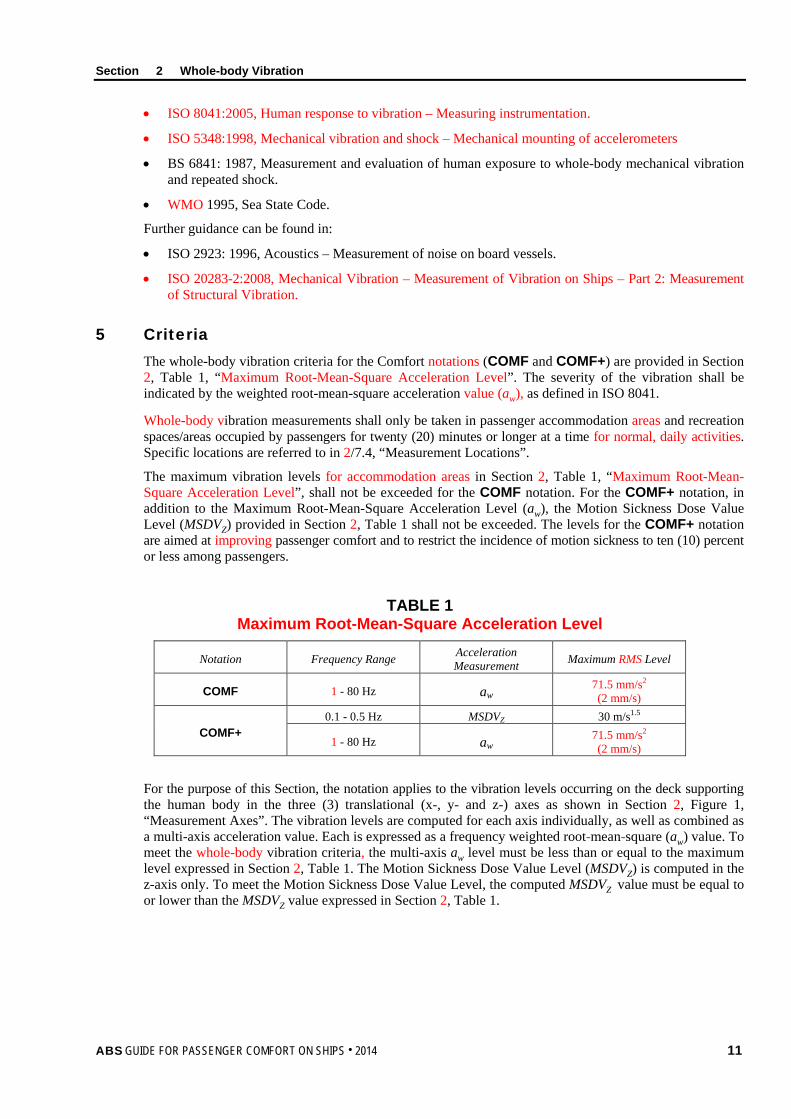
TABLE 1 Maximum Root-Mean-Square Acceleration Level
Notation Frequency Range Acceleration Measurement Maximum RMS Level
COMF 1 - 80 Hz aw 71.5 mm/s2 (2 mm/s)
COMF+ 0.1 - 0.5 Hz MSDVZ 30 m/s1.5
1 - 80 Hz aw 71.5 mm/s2 (2 mm/s)
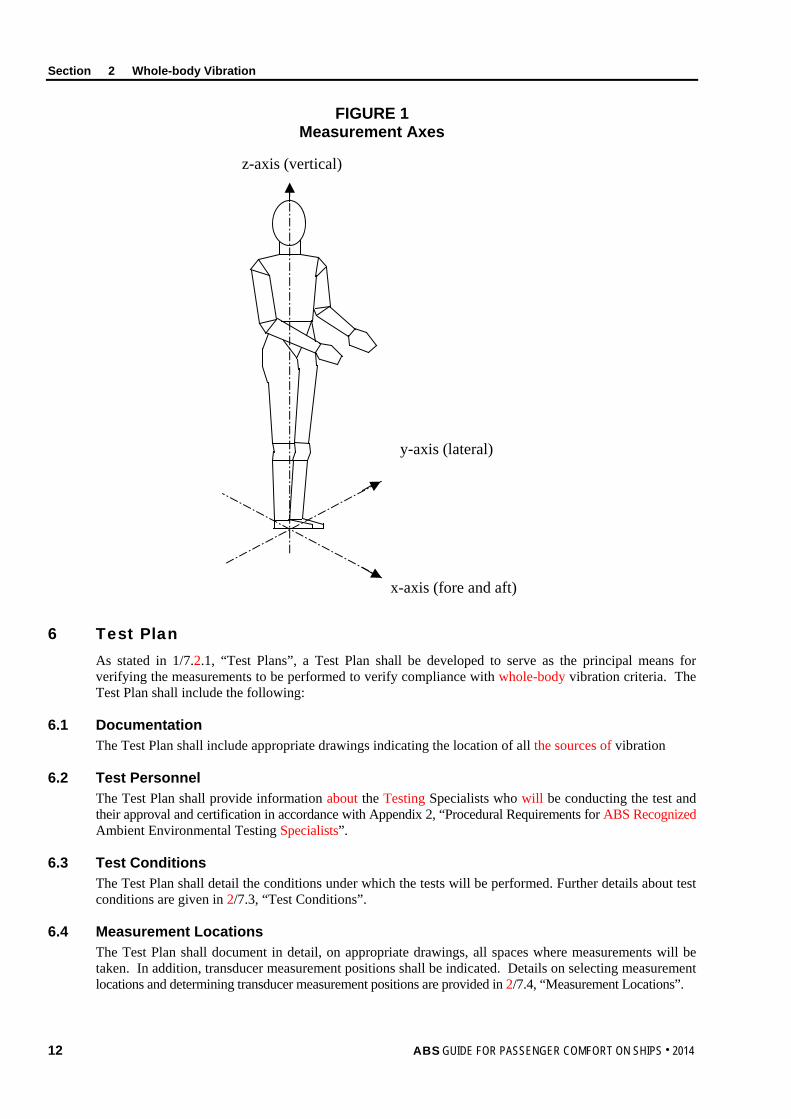
For the purpose of this Section, the notation applies to the vibration levels occurring on the deck supporting the human body in the three (3) translational (x-, y- and z-) axes as shown in Section 2, Figure 1, “Measurement Axes”. The vibration levels are computed for each axis individually, as well as combined as a multi-axis acceleration value. Each is expressed as a frequency weighted root-mean-square (aw) value. To meet the whole-body vibration criteria, the multi-axis aw level must be less than or equal to the maximum level expressed in Section 2, Table 1. The Motion Sickness Dose Value Level (MSDVZ) is computed in the z-axis only. To meet the Motion Sickness Dose Value Level, the computed MSDVZ value must be equal to or lower than the MSDVZ value expressed in Section 2, Table 1.
Section 2 Whole-body Vibration
12 ABS GUIDE FOR PASSENGER COMFORT ON SHIPS . 2014
FIGURE 1 Measurement Axes
x-axis (fore and aft)
y-axis (lateral)
z-axis (vertical)
6 Test Plan As stated in 1/7.2.1, “Test Plans”, a Test Plan shall be developed to serve as the principal means for verifying the measurements to be performed to verify compliance with whole-body vibration criteria. The Test Plan shall include the following:
6.1 Documentation The Test Plan shall include appropriate drawings indicating the location of all the sources of vibration
6.2 Test Personnel The Test Plan shall provide information about the Testing Specialists who will be conducting the test and their approval and certification in accordance with Appendix 2, “Procedural Requirements for ABS Recognized Ambient Environmental Testing Specialists”.
6.3 Test Conditions The Test Plan shall detail the conditions under which the tests will be performed. Further details about test conditions are given in 2/7.3, “Test Conditions”.
6.4 Measurement Locations The Test Plan shall document in detail, on appropriate drawings, all spaces where measurements will be taken. In addition, transducer measurement positions shall be indicated. Details on selecting measurement locations and determining transducer measurement positions are provided in 2/7.4, “Measurement Locations”.
Section 2 Whole-body Vibration
ABS GUIDE FOR PASSENGER COMFORT ON SHIPS . 2014 13
6.5 Data Acquisition and Instruments The Test Plan shall provide information regarding the methods and instrumentation to be used for measurement and data collection. Instrumentation specification details shall include type of instruments to be used, accuracy, calibration, sensitivity, conformance with ISO 8041 and frequency range. More details on data acquisition and instruments are provided in 2/7.2, “Data Acquisition and Instruments”.
6.6 Data Analysis The Test Plan shall provide information regarding the methods, software and instrumentation to be used for data analysis.
6.7 Test Schedule The Test Plan shall provide information regarding the proposed test schedule.
7 Test Requirements
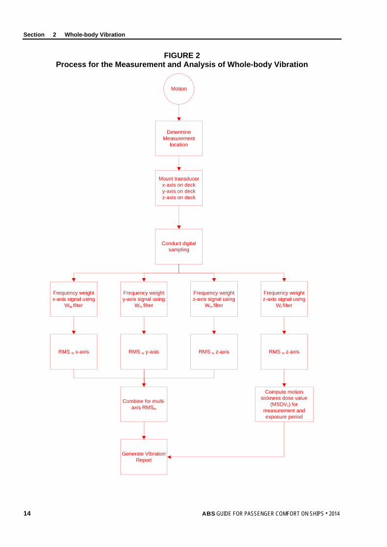
7.1 General Whole-body vibration measurements shall be in accordance with the procedures described in ISO 6954. When the procedures described in this Guide deviate from any requirements or procedures mentioned in ISO 6954, the more stringent requirement shall take precedence.
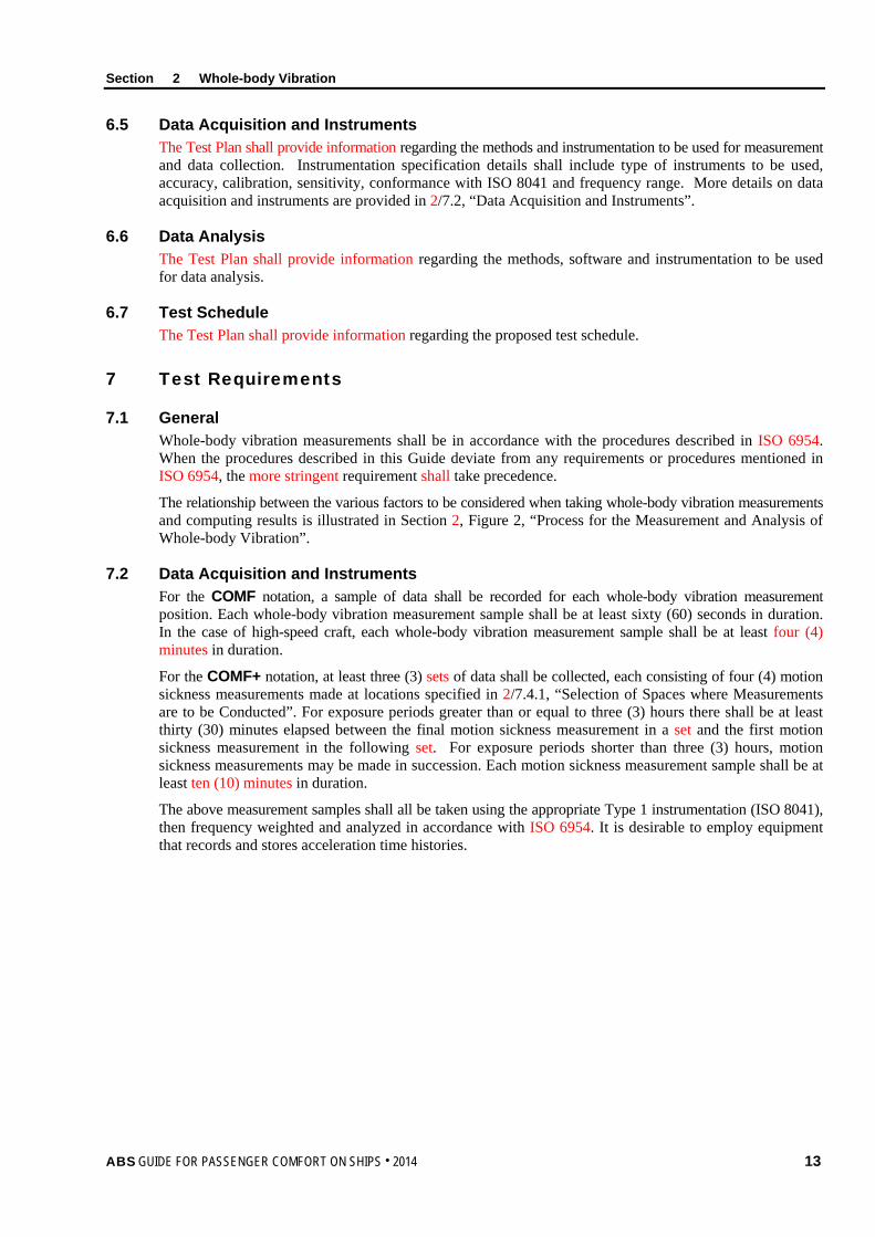
The relationship between the various factors to be considered when taking whole-body vibration measurements and computing results is illustrated in Section 2, Figure 2, “Process for the Measurement and Analysis of Whole-body Vibration”.
7.2 Data Acquisition and Instruments For the COMF notation, a sample of data shall be recorded for each whole-body vibration measurement position. Each whole-body vibration measurement sample shall be at least sixty (60) seconds in duration. In the case of high-speed craft, each whole-body vibration measurement sample shall be at least four (4) minutes in duration.
For the COMF+ notation, at least three (3) sets of data shall be collected, each consisting of four (4) motion sickness measurements made at locations specified in 2/7.4.1, “Selection of Spaces where Measurements are to be Conducted”. For exposure periods greater than or equal to three (3) hours there shall be at least thirty (30) minutes elapsed between the final motion sickness measurement in a set and the first motion sickness measurement in the following set. For exposure periods shorter than three (3) hours, motion sickness measurements may be made in succession. Each motion sickness measurement sample shall be at least ten (10) minutes in duration.
The above measurement samples shall all be taken using the appropriate Type 1 instrumentation (ISO 8041), then frequency weighted and analyzed in accordance with ISO 6954. It is desirable to employ equipment that records and stores acceleration time histories.
Section 2 Whole-body Vibration
14 ABS GUIDE FOR PASSENGER COMFORT ON SHIPS . 2014
FIGURE 2 Process for the Measurement and Analysis of Whole-body Vibration
Motion
Determine Measurement
location
Mount transducerx-axis on decky-axis on deckz-axis on deck
Conduct digital sampling
Frequency weight y-axis signal using
Wm filter
Frequency weight x-axis signal using
Wm filter
Combine for multi-axis RMSw
RMS w x-axis RMS w y-axis RMS w z-axis
Generate Vibration Report
Frequency weight z-axis signal using
Wm filter
Frequency weight z-axis signal using
Wt filter
RMS w z-axis
Compute motion sickness dose value
(MSDVz) for measurement and exposure period
Section 2 Whole-body Vibration
ABS GUIDE FOR PASSENGER COMFORT ON SHIPS . 2014 15
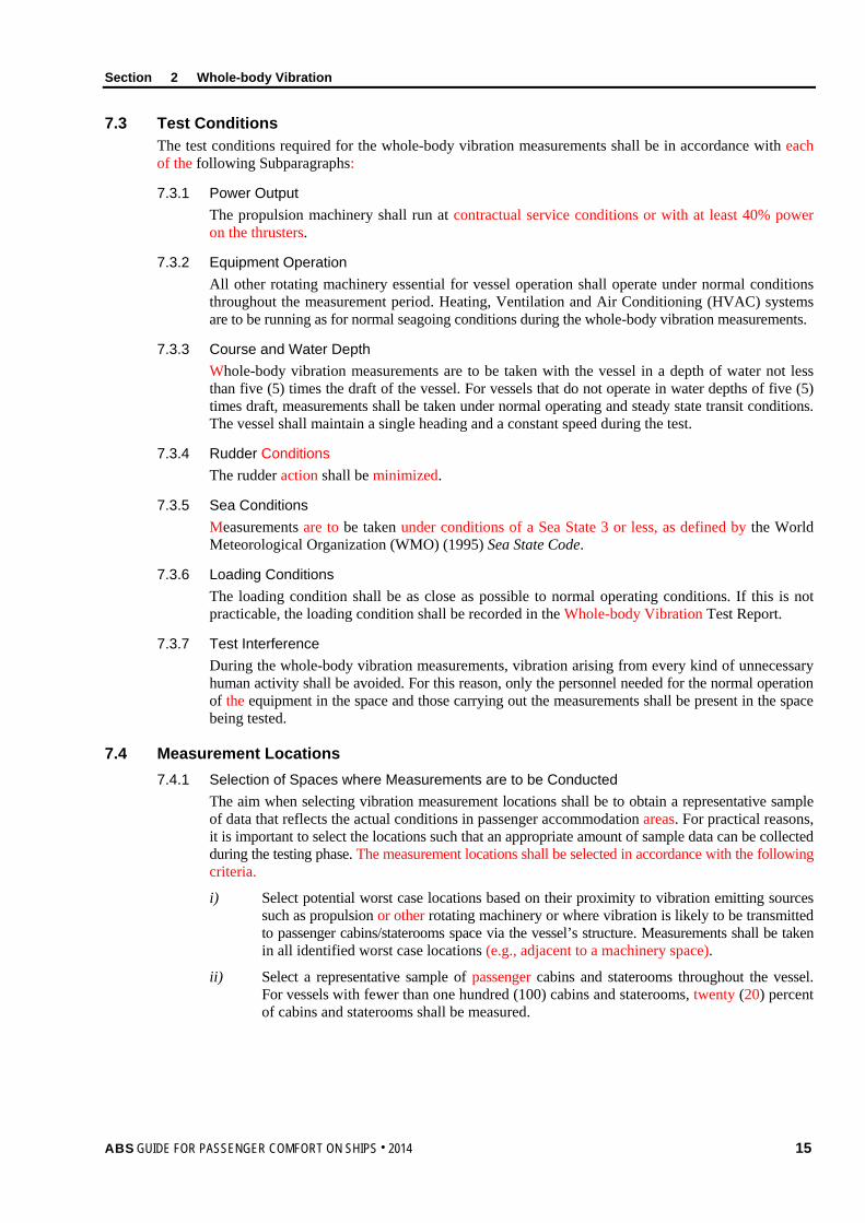
7.3 Test Conditions The test conditions required for the whole-body vibration measurements shall be in accordance with each of the following Subparagraphs:
7.3.1 Power Output The propulsion machinery shall run at contractual service conditions or with at least 40% power on the thrusters.
7.3.2 Equipment Operation All other rotating machinery essential for vessel operation shall operate under normal conditions throughout the measurement period. Heating, Ventilation and Air Conditioning (HVAC) systems are to be running as for normal seagoing conditions during the whole-body vibration measurements.
7.3.3 Course and Water Depth Whole-body vibration measurements are to be taken with the vessel in a depth of water not less than five (5) times the draft of the vessel. For vessels that do not operate in water depths of five (5) times draft, measurements shall be taken under normal operating and steady state transit conditions. The vessel shall maintain a single heading and a constant speed during the test.
7.3.4 Rudder Conditions The rudder action shall be minimized.
7.3.5 Sea Conditions Measurements are to be taken under conditions of a Sea State 3 or less, as defined by the World Meteorological Organization (WMO) (1995) Sea State Code.
7.3.6 Loading Conditions The loading condition shall be as close as possible to normal operating conditions. If this is not practicable, the loading condition shall be recorded in the Whole-body Vibration Test Report.
7.3.7 Test Interference During the whole-body vibration measurements, vibration arising from every kind of unnecessary human activity shall be avoided. For this reason, only the personnel needed for the normal operation of the equipment in the space and those carrying out the measurements shall be present in the space being tested.
7.4 Measurement Locations 7.4.1 Selection of Spaces where Measurements are to be Conducted
The aim when selecting vibration measurement locations shall be to obtain a representative sample of data that reflects the actual conditions in passenger accommodation areas. For practical reasons, it is important to select the locations such that an appropriate amount of sample data can be collected during the testing phase. The measurement locations shall be selected in accordance with the following criteria.
i) Select potential worst case locations based on their proximity to vibration emitting sources such as propulsion or other rotating machinery or where vibration is likely to be transmitted to passenger cabins/staterooms space via the vessel’s structure. Measurements shall be taken in all identified worst case locations (e.g., adjacent to a machinery space).
ii) Select a representative sample of passenger cabins and staterooms throughout the vessel. For vessels with fewer than one hundred (100) cabins and staterooms, twenty (20) percent of cabins and staterooms shall be measured.
Section 2 Whole-body Vibration
16 ABS GUIDE FOR PASSENGER COMFORT ON SHIPS . 2014
For vessels with one hundred (100) or more cabins and staterooms, apply the following:
• In the forward one-third (1/3) of the vessel, five (5) percent or 1 in 20 of cabins and staterooms shall be measured
• In the midsection (center 1/3) of the vessel, four (4) percent or 1 in 25 of cabins and staterooms shall be measured
• In the aft one-third (1/3) of the vessel, seven (7) percent 1 in 15 of the cabins and staterooms shall be measured.
Within each one-third (1/3) section of the vessel, measurement locations shall be distributed throughout the length of each section and on each deck.
iii) Where a single instance of one (1) type of passenger space exists within the vessel, that location shall be selected for measurement.
iv) Regardless of the number of passenger cabins and staterooms on a passenger vessel, attention must be given to selecting a variety of locations port, starboard, fore, amidships, and aft. The worst case locations can be considered part of the representative sample for cabins and staterooms, if applicable.
For the COMF+ notation, motion sickness measurements shall be taken in addition to the whole-body vibration measurements. Motion sickness measurement locations shall be made in the most aft-and-port, aft-and-starboard, forward-and-port and forward-and-starboard passenger spaces, irrespective of deck level.
7.4.2 Walkthrough Verification Inspection Locations All spaces occupied by passengers shall be subject to a walkthrough inspection by the ABS Surveyor. The number and locations of the walkthrough inspections will be determined by the ABS Surveyor. The purpose of the walkthrough verification is to subjectively assess the vibration qualities. At the discretion of the ABS Surveyor, additional measurements may be required.
7.4.3 Transducer Measurement Positions Vibration transducers (accelerometers) shall be located and attached properly to the deck surface to measure the vibration at the interface between the standing passenger and the source of vibration. The mounting of accelerometers shall comply with ISO 5348. When the vibration enters the human body from a non-rigid or resilient material (e.g., deck covering) secure the transducers with a suitably formed mount that does not alter the pressure distribution on the surface of the deck covering.
In cabins or staterooms, the vibration transducers shall be placed on the deck in the center of the space. (Note: This location may not provide the maximum vibration levels for this particular space. The objective is to minimize the number of measurements yet still obtain a fair and representative sample of the exposure conditions of the person occupying the cabin.)
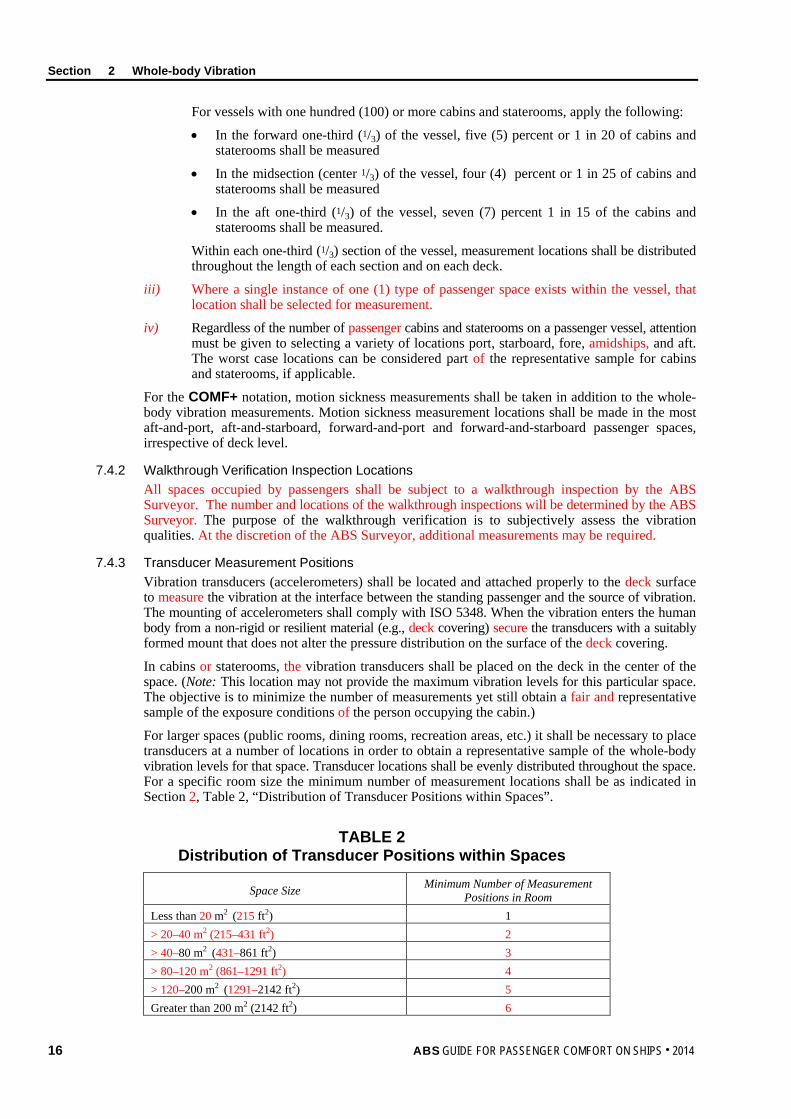
For larger spaces (public rooms, dining rooms, recreation areas, etc.) it shall be necessary to place transducers at a number of locations in order to obtain a representative sample of the whole-body vibration levels for that space. Transducer locations shall be evenly distributed throughout the space. For a specific room size the minimum number of measurement locations shall be as indicated in Section 2, Table 2, “Distribution of Transducer Positions within Spaces”.
TABLE 2
Distribution of Transducer Positions within Spaces
Space Size Minimum Number of Measurement Positions in Room
Less than 20 m2 (215 ft2) 1 > 20–40 m2 (215–431 ft2) 2 > 40–80 m2 (431–861 ft2) 3 > 80–120 m2 (861–1291 ft2) 4 > 120–200 m2 (1291–2142 ft2) 5 Greater than 200 m2 (2142 ft2) 6
Section 2 Whole-body Vibration
ABS GUIDE FOR PASSENGER COMFORT ON SHIPS . 2014 17
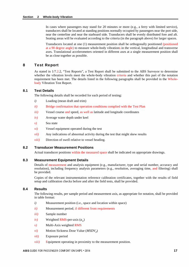
In cases where passengers may stand for 20 minutes or more (e.g., a ferry with limited service), transducers shall be located at standing positions normally occupied by passengers near the port side, near the centerline and near the starboard side. Transducers shall be evenly distributed fore and aft. Seating areas will be evaluated according to the criteria (in the paragraph above) for larger spaces.
Transducers located at one (1) measurement position shall be orthogonally positioned (positioned at a 90 degree angle) to measure whole-body vibrations in the vertical, longitudinal and transverse axes. Translational accelerometers oriented in different axes at a single measurement position shall be as close together as possible.
8 Test Report As stated in 1/7.2.2, “Test Reports”, a Test Report shall be submitted to the ABS Surveyor to determine whether the vibration levels meet the whole-body vibration criteria and whether this part of the notation requirement has been met. The details listed in the following paragraphs shall be provided in the Whole-body Vibration Test Report.
8.1 Test Details The following details shall be recorded for each period of testing:
i) Loading (mean draft and trim)
ii) Bridge confirmation that operation conditions complied with the Test Plan
iii) Vessel course and speed, as well as latitude and longitude coordinates
iv) Average water depth under keel
v) Sea state
vi) Vessel equipment operated during the test
vii) Any indications of abnormal activity during the test that might skew results
viii) Direction of swell relative to vessel heading.
8.2 Transducer Measurement Positions Actual transducer positions within the measured space shall be indicated on appropriate drawings.
8.3 Measurement Equipment Details Details of measurement and analysis equipment (e.g., manufacturer, type and serial number, accuracy and resolution), including frequency analysis parameters (e.g., resolution, averaging time, and filtering) shall be provided.
Copies of the relevant instrumentation reference calibration certificates, together with the results of field setup and calibration checks before and after the field tests, shall be provided.
8.4 Results The following results, per sample period and measurement axis, as appropriate for notation, shall be provided in table format:
i) Measurement position (i.e., space and location within space)
ii) Measurement period, if different from requirements
iii) Sample number
iv) Weighted RMS-per-axis (aw)
v) Multi-Axis weighted RMS
vi) Motion Sickness Dose Value (MSDVZ)
vii) Exposure period
viii) Equipment operating in proximity to the measurement position.
Section 2 Whole-body Vibration
18 ABS GUIDE FOR PASSENGER COMFORT ON SHIPS . 2014
For all the remaining spaces that were checked through walkthrough verification inspection and spot check measurements, the following information shall be provided: i) Name and number of space
ii) Walkthrough inspection observations
iii) Measurement results, if necessary
8.5 Deviations All deviations from the approved Test Plan shall be reported.
8.6 Surveyor Witnessing Documentation The equipment calibration and data collection process of the whole-body vibration tests conducted at sea shall be witnessed by an ABS Surveyor. The ABS Surveyor shall provide documentation stating whether all steps of the vibration testing were completed to their satisfaction. A copy of the witnessing document shall be given to the person conducting the onboard testing, for insertion into the final Whole-body Vibration Test Report. The original shall be retained for ABS’ files.
9 Results The Whole-body Vibration Test Report shall be reviewed by the ABS Surveyor against the appropriate COMF and COMF+ criteria for notation confirmation.
ABS GUIDE FOR PASSENGER COMFORT ON SHIPS . 2014 19
S e c t i o n 3 : N o i s e
S E C T I O N 3 Noise
1 Background A large amount of research has been performed on the effects of noise on humans. Established or commonly used criteria exist for the effects of noise on speech communication, hearing loss, sleep, concentration, and “annoyance”. These have provided a basis for the criteria in this Guide.
A detailed discussion of the effects of noise on human performance, health, and comfort is found in Kryter (1994), The Handbook of Hearing and the Effects of Noise: Physiology, Psychology and Public Health.
2 Scope In this Section, noise criteria have been selected to improve passenger comfort. In this instance, “comfort” means the ability of the passengers to use a space for its intended purpose, with minimal interference or annoyance from noise.
This Section primarily applies to passenger accommodation areas and recreation spaces occupied for twenty (20) minutes or longer at any one time during normal daily activities. Examples of such spaces include cabins, staterooms, dining, and recreation spaces.
Compliance with this Section is a prerequisite for the Comfort (COMF) or Comfort Plus (COMF+) notation confirmation.
3 Terminology A-weighted Sound Pressure Level: The magnitude of a sound, expressed in decibels (i.e., 20 micropascals); the various frequency components are adjusted according to the A-weighted values given in IEC 61672-1 in order to account for the frequency response characteristics of the human ear. The symbol is LA; the unit is dB(A). The measurement LAeq is an equivalent continuous A-weighted sound.
Calibration Checks: Field calibration of a measuring instrument conducted before and after a field test using a reference calibrated signal or through zero calibration.
Equivalent Continuous A-weighted Sound Pressure Level: The A-weighted sound pressure level of a notional steady sound over a certain time interval, which would have the same acoustic energy as the variable-loudness real sound under consideration, over the same time interval. The symbol is LAeq; the unit is dB(A).
Reference Calibration: Calibration of measuring instrument conducted by an accredited Testing and Calibration Laboratory with traceability to a national or international standard.
4 Associated Documentation The following documents provide details about Test Plan preparation, test measurement procedures and/or Test Reporting:
• ISO 2923: 1996: Acoustics – Measurement of noise on board vessels
• IEC 61672-1:2004, Electroacoustics – Sound Level Meters – Part 1: Specifications IEC 61672-1 (2004)
• IMO Resolution A.468(XII): 1981, Code on noise levels on board ships
• WMO: 1995, Sea State Code
Section 3 Noise
20 ABS GUIDE FOR PASSENGER COMFORT ON SHIPS . 2014
5 Criteria
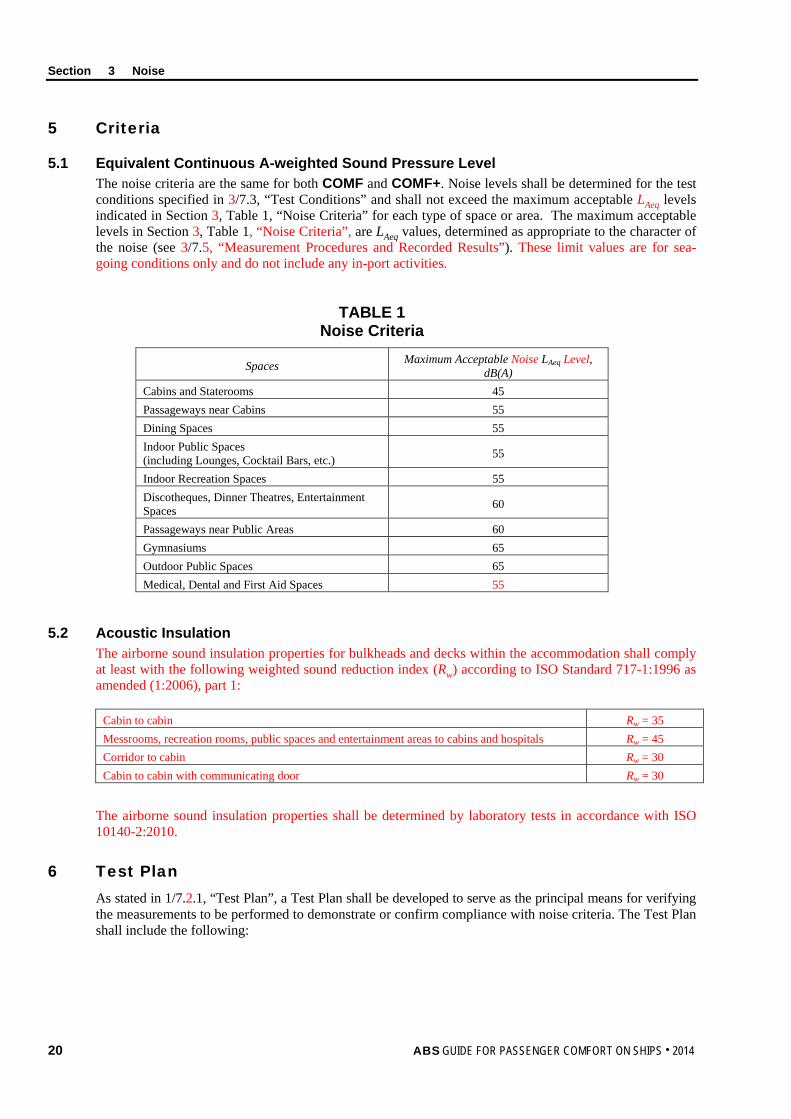
5.1 Equivalent Continuous A-weighted Sound Pressure Level The noise criteria are the same for both COMF and COMF+. Noise levels shall be determined for the test conditions specified in 3/7.3, “Test Conditions” and shall not exceed the maximum acceptable LAeq levels indicated in Section 3, Table 1, “Noise Criteria” for each type of space or area. The maximum acceptable levels in Section 3, Table 1, “Noise Criteria”, are LAeq values, determined as appropriate to the character of the noise (see 3/7.5, “Measurement Procedures and Recorded Results”). These limit values are for sea-going conditions only and do not include any in-port activities.
TABLE 1 Noise Criteria
Spaces Maximum Acceptable Noise LAeq Level, dB(A)
Cabins and Staterooms 45 Passageways near Cabins 55 Dining Spaces 55 Indoor Public Spaces (including Lounges, Cocktail Bars, etc.) 55
Indoor Recreation Spaces 55 Discotheques, Dinner Theatres, Entertainment Spaces 60
Passageways near Public Areas 60 Gymnasiums 65 Outdoor Public Spaces 65 Medical, Dental and First Aid Spaces 55
5.2 Acoustic Insulation The airborne sound insulation properties for bulkheads and decks within the accommodation shall comply at least with the following weighted sound reduction index (Rw) according to ISO Standard 717-1:1996 as amended (1:2006), part 1:
Cabin to cabin Rw = 35 Messrooms, recreation rooms, public spaces and entertainment areas to cabins and hospitals Rw = 45 Corridor to cabin Rw = 30 Cabin to cabin with communicating door Rw = 30
The airborne sound insulation properties shall be determined by laboratory tests in accordance with ISO 10140-2:2010.
6 Test Plan As stated in 1/7.2.1, “Test Plan”, a Test Plan shall be developed to serve as the principal means for verifying the measurements to be performed to demonstrate or confirm compliance with noise criteria. The Test Plan shall include the following:
Section 3 Noise
ABS GUIDE FOR PASSENGER COMFORT ON SHIPS . 2014 21
6.1 Documentation The Test Plan shall include appropriate design information including noise specifications for the vessel. It should also include layout drawings indicating the locations of all noise sources and noise generating equipment. The information shall be of such detail to enable an ABS Engineer or Surveyor to verify compliance with the criteria set in this Guide.
The Test Plan shall be submitted to ABS Engineering for review and approval.
6.2 Test Personnel The Test Plan shall provide information about the Testing Specialist who will be conducting the test and their approval and certification in accordance with Appendix 2, “Procedural Requirements for ABS Recognized Ambient Environmental Testing Specialists”.
6.3 Test Conditions The Test Plan shall detail the conditions under which the tests will be performed. Further details about test conditions are given in 3/7.3, “Test Conditions”.
6.4 Measurement Locations The Test Plan shall document, in detail, on appropriate drawings, all passenger spaces or areas where measurements will be taken. In addition, measurement positions within these spaces shall be indicated on the drawings. Details on selecting measurement locations are provided in 3/7.4, “Measurement Locations”.
6.5 Data Acquisition and Instruments The Test Plan shall provide information regarding the methods and instrumentation to be used for measurement and data collection. Instrumentation specification details shall include type of instruments to be used, accuracy, calibration and sensitivity. More details on data acquisition and instruments are provided in 3/7.2, “Data Acquisition and Instruments”.
6.6 Data Analysis The Test Plan shall provide information regarding the methods, software and instrumentation to be used for data analysis.
6.7 Test Schedule The Test Plan shall provide information the proposed test schedule.
7 Test Requirements
7.1 General In general, the noise measurements shall be carried out in accordance with the requirements of IMO Resolution A.468(XII) Code on Noise Levels on-board ships. However, where the IMO requirements differ from those in this Guide, the more stringent requirement shall take precedence.
7.2 Data Acquisition and Instruments The integrating-averaging sound level meter shall meet the requirements for a Type 1 instrument specified in IEC 61672-1.
For each location sampled, a measurement shall be taken in accordance with the requirements in 3/7.3, “Test Conditions”.
7.3 Test Conditions The test conditions required for the noise measurements shall be in accordance with each of the following Subparagraphs based on ISO 2923.
Section 3 Noise
22 ABS GUIDE FOR PASSENGER COMFORT ON SHIPS . 2014
7.3.1 Power Output The propulsion machinery shall run at contractual service conditions or with at least 40% power on the thrusters.
7.3.2 Equipment Operation All machinery essential for vessel operation shall operate under normal conditions throughout the measurement period. Heating, Ventilation and Air Conditioning (HVAC) systems are to be running as for normal seagoing conditions during the noise measurements.
7.3.3 Course and Water Depth Noise measurements are to be taken with the vessel in a depth of water greater than five (5) times the draft of the passenger vessel. For vessels that do not operate in water depths of five (5) times draft, measurements shall be taken under normal operating and transit conditions. The course of the vessel shall be as straight as possible and at a constant speed.
7.3.4 Rudder Conditions The rudder action shall be minimized.
7.3.5 Sea Conditions Measurements are to be taken under conditions of a Sea State 3 or less, as defined by the World Meteorological Organization (WMO) (1995) Sea State Code.
7.3.6 Loading Conditions The loading condition of a passenger vessel shall be as close as possible to normal operating conditions. If this is not practicable, the loading condition shall be recorded in the Noise Test Report.
7.3.7 Test Interference During the noise measurements, noise arising from every kind of unnecessary human activity shall be avoided. For this reason, only the personnel needed for the normal operation of the equipment in the space and those carrying out the measurements shall be present in the space being tested.
Doors and windows shall be closed, except where they are normally left open. Any open doors or windows shall be noted in the Noise Test Report. Spaces shall be furnished with all usual equipment and furnishings normally found in the space. Equipment shall be configured to operate in its normal operating mode.
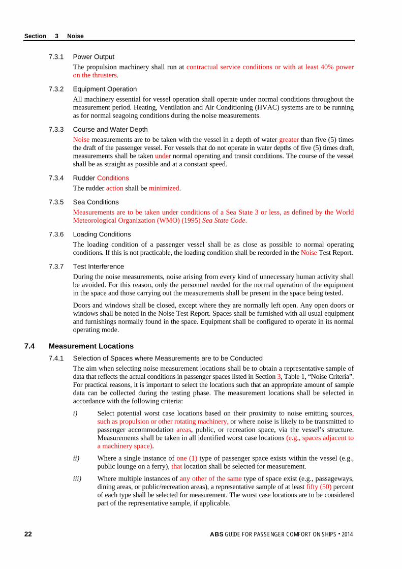
7.4 Measurement Locations 7.4.1 Selection of Spaces where Measurements are to be Conducted
The aim when selecting noise measurement locations shall be to obtain a representative sample of data that reflects the actual conditions in passenger spaces listed in Section 3, Table 1, “Noise Criteria”. For practical reasons, it is important to select the locations such that an appropriate amount of sample data can be collected during the testing phase. The measurement locations shall be selected in accordance with the following criteria:
i) Select potential worst case locations based on their proximity to noise emitting sources, such as propulsion or other rotating machinery, or where noise is likely to be transmitted to passenger accommodation areas, public, or recreation space, via the vessel’s structure. Measurements shall be taken in all identified worst case locations (e.g., spaces adjacent to a machinery space).
ii) Where a single instance of one (1) type of passenger space exists within the vessel (e.g., public lounge on a ferry), that location shall be selected for measurement.
iii) Where multiple instances of any other of the same type of space exist (e.g., passageways, dining areas, or public/recreation areas), a representative sample of at least fifty (50) percent of each type shall be selected for measurement. The worst case locations are to be considered part of the representative sample, if applicable.
Section 3 Noise
ABS GUIDE FOR PASSENGER COMFORT ON SHIPS . 2014 23
iv) Select a representative sample of passenger cabins and staterooms throughout the vessel. For vessels with less than 20 passenger cabins, fifty (50) percent of cabins on each deck shall be selected. For vessels with greater than 20 passenger cabins, thirty (30) percent of cabins on each deck shall be selected. These measurement locations must be selected at locations port, starboard, fore, amidships, and aft. The worst case locations can be considered part as the representative sample for passenger cabins and staterooms, if applicable.
7.4.2 Walkthrough Verification Inspection Locations All spaces normally occupied by passengers shall be subject to a walkthrough inspection by the ABS Surveyor. The number and locations of the walkthrough inspections will be determined by the ABS Surveyor. The purpose of the walkthrough verification is to subjectively assess the noise qualities. At the discretion of the ABS Surveyor, additional measurements may be required.
7.4.3 Measurement Positions The measurement positions described below are taken or adapted from ISO 2923 and IMO Resolution A.468(XII) (1981).
Measure at positions where passengers will be seated or standing. The microphone shall be at a height of approximately 1200 mm (47 in.) from the deck to represent seated persons and approximately 1600 mm (63 in.) from the deck to represent standing persons as appropriate for the measurement position. In cabins, measure in the middle of the space.
For all measurements, the microphone shall not be closer than 500 mm (20 in.) from the boundary surface (e.g., bulkhead) of a space. The measurement time shall be at least fifteen (15) seconds and shall be long enough to enable the measurement of the equivalent continuous A-weighted sound pressure level for any specified time interval within the stated limits of overall measurement uncertainty.
7.5 Measurement Procedures and Recorded Results 7.5.1 Persons Present During Measurements
When Testing Specialist personnel are conducting noise level measurements in any space, only personnel necessary for the operation of that space should be present.
7.5.2 Sampling Duration Equivalent continuous A-weighted sound pressure levels (LAeq) shall be reported for each measurement location. The LAeq sampling duration shall be sufficient to achieve a stable reading. Sampling time shall be fifteen (15) seconds or longer.
7.5.3 Cyclic Noise If the noise within a space is cyclic, the LAeq sampling duration shall be sufficient to capture an integer number of complete cycles. If a long-duration sample is judged impractical, an LAeq value shall be determined and reported for the high-noise portion of the cycle.
7.5.4 Intermittent Noise If the noise within a space is present intermittently, an LAeq value shall be determined and reported for a period of high-level noise.
7.5.5 HVAC Related Noise If HVAC system-related noise is a large contributor to the noise level in the space, a noise measurement shall be made approximately 300 mm (12 in.) from the vent, measured in line with the direction of airflow, and recorded in the Noise Test Report.
8 Test Report As stated in 1/7.2.2, “Test Reports”, a Test Report shall be submitted to the ABS Surveyor to determine whether the noise levels are at or below the limits and whether this part of the notation requirement has been met. The details listed in the following paragraphs shall be provided in the Noise Test Report.
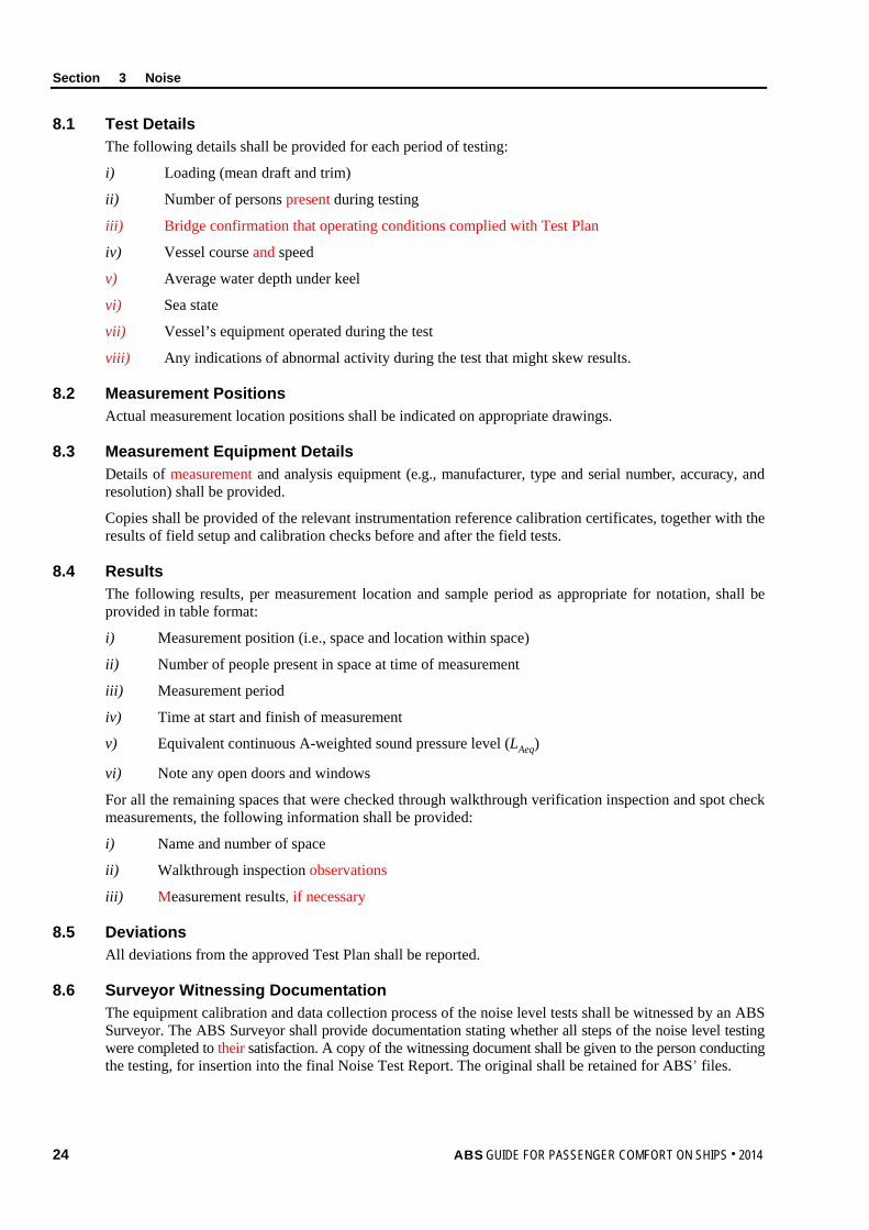
Section 3 Noise
24 ABS GUIDE FOR PASSENGER COMFORT ON SHIPS . 2014
8.1 Test Details The following details shall be provided for each period of testing:
i) Loading (mean draft and trim)
ii) Number of persons present during testing
iii) Bridge confirmation that operating conditions complied with Test Plan
iv) Vessel course and speed
v) Average water depth under keel
vi) Sea state
vii) Vessel’s equipment operated during the test
viii) Any indications of abnormal activity during the test that might skew results.
8.2 Measurement Positions Actual measurement location positions shall be indicated on appropriate drawings.
8.3 Measurement Equipment Details Details of measurement and analysis equipment (e.g., manufacturer, type and serial number, accuracy, and resolution) shall be provided.
Copies shall be provided of the relevant instrumentation reference calibration certificates, together with the results of field setup and calibration checks before and after the field tests.
8.4 Results The following results, per measurement location and sample period as appropriate for notation, shall be provided in table format:
i) Measurement position (i.e., space and location within space)
ii) Number of people present in space at time of measurement
iii) Measurement period
iv) Time at start and finish of measurement
v) Equivalent continuous A-weighted sound pressure level (LAeq)
vi) Note any open doors and windows
For all the remaining spaces that were checked through walkthrough verification inspection and spot check measurements, the following information shall be provided:
i) Name and number of space
ii) Walkthrough inspection observations
iii) Measurement results, if necessary
8.5 Deviations All deviations from the approved Test Plan shall be reported.
8.6 Surveyor Witnessing Documentation The equipment calibration and data collection process of the noise level tests shall be witnessed by an ABS Surveyor. The ABS Surveyor shall provide documentation stating whether all steps of the noise level testing were completed to their satisfaction. A copy of the witnessing document shall be given to the person conducting the testing, for insertion into the final Noise Test Report. The original shall be retained for ABS’ files.
Section 3 Noise
ABS GUIDE FOR PASSENGER COMFORT ON SHIPS . 2014 25
9 Results The Noise Test Report and test results shall be reviewed by the ABS Surveyor against the noise criteria for notation confirmation.
26 ABS GUIDE FOR PASSENGER COMFORT ON SHIPS . 2014
S e c t i o n 4 : I n d o o r C l i m a t e
S E C T I O N 4 Indoor Climate
1 Background
Thermal comfort is defined in ISO 7730 as “…that condition of mind which expresses satisfaction with the thermal environment”. The sensation of thermal comfort is therefore largely subjective and will vary from person to person. Due to differences in metabolism and expectations, there are distinct individual differences among people’s perception of comfort as a function of temperature, humidity, and other atmospheric conditions. Acclimatization, habits and expectations influence perceived comfort. These individual differences make it difficult to specify a single thermal environment that will be satisfactory to everyone. A thermal environment is therefore typically defined to be acceptable to at least eighty (80) percent of the occupants of an interior space.
Individually, the perception of thermal comfort is largely determined by the interaction of thermal environmental factors such as air temperature, air velocity, relative humidity, and factors related to activity and clothing.
The thermal control or Heating, Ventilation, and Air Conditioning (HVAC) systems on a vessel should be designed to effectively control the indoor thermal environmental parameters to within acceptable limits to facilitate the thermal comfort of the passengers.
2 Scope
This Section provides the assessment criteria, verification and measurement methodology for indoor climate relating to comfort on passenger vessels. The criteria defined are based on currently available standards and were selected to provide an index of passenger thermal comfort.
The thermal environmental variables covered by this Guide include the ambient qualities of air temperature, air velocity and relative humidity. The vertical thermal gradient as well as the horizontal thermal gradient help determine the passenger’s comfort or discomfort. The vertical gradient measures the differential of temperature of the relative height of the passenger’s head and feet. The horizontal gradient is measured with the temperature of the inner side of the cabin’s bulkhead and the average air temperature within the space.
The thermal environmental criteria provided in this Guide are for persons wearing typical indoor clothing occupied with light, primarily sedentary activities and resulting in a thermal environment acceptable to at least eighty (80) percent of the passengers.
This Section applies to indoor accommodation areas and recreation spaces occupied by passengers for twenty (20) minutes or longer at any one time during normal, daily activities. Examples of passenger spaces include cabins, staterooms, public seating spaces, dining areas, and hospitals.
Compliance with this Section is a prerequisite for the Comfort (COMF) or Comfort Plus (COMF+) notation confirmation.
3 Terminology Air Temperature: The temperature of the air surrounding a person, measured with a standard thermometer.
Air Velocity: The rate of displacement of ambient air in a specific direction in meters-per-second (m/s) or feet-per-second (ft/s).
Horizontal Gradient: The difference between the inside surface temperatures of the bulkheads bounding the bunk and the average air temperature within the cabin. This is used as an indication of potential thermal discomfort due to radiant thermal sources within the cabin.
Section 4 Indoor Climate
ABS GUIDE FOR PASSENGER COMFORT ON SHIPS . 2014 27
HVAC Zone: A space or group of spaces that is (are) independently controlled for temperature, humidity, and air distribution. A zone usually comprises common duct work fed from an air handler.
Reference Calibration: Calibration of measuring instrument conducted by an accredited Testing and Calibration Laboratory, with traceability to a national or international standard.
Relative Humidity (RH): The ratio of the amount of vapor contained in the air (absolute humidity) to the maximum amount of vapor the air can hold at a given temperature before precipitation (condensation) occurs.
Thermal Comfort: Subjective index of “that condition of mind which expresses satisfaction with the thermal environment”.
Ventilation: Ventilation is the process of supplying air to and removing air from any space by natural or mechanical means. From the standpoint of comfort and health, ventilation issues involve both quantity and quality.
Vertical Gradient: The vertical air temperature difference within an enclosed space. The vertical gradient is used as an indication of potential local discomfort at the head and feet.
4 Associated Documentation The following documents provide details about Test Plan preparation, test measurement procedures and/or Test Reporting:
• ANSI/ASHRAE 55a, (2010). Thermal Environmental Conditions for Human Occupancy
• ANSI/ASHRAE (15) (2010). Practices for Measuring, Testing, Adjusting, and Balancing Shipboard HVAC&R Systems
• ISO 7726 (E), (1998), Ergonomics of the thermal environment – Instruments for measuring physical quantities
• NEBB, (2005). Procedural Standards for testing, adjusting, balancing of environmental systems.
5 Criteria The indoor climate criteria for the COMF and COMF+ notations are identical and are provided in Section 4, Table 1, “Summary of Indoor Climate Requirements”.
Indoor climate measurements shall be taken only in indoor passenger accommodation areas and recreation spaces occupied by passengers for twenty (20) minutes or longer at a time. Specific measurement locations are discussed in 4/7.4, “Measurement Locations”.
The thermal environmental comfort ranges and conditions shall be achievable, under the test conditions specified in 4/7.3, “Test Conditions”, for normal operating conditions, in all passenger spaces.
The COMF and COMF+ notations criteria are aimed at enhancing passenger comfort by making provisions for adjusting indoor climate conditions, with regard to air temperature and air velocity, to suit personal needs within a particular space.
5.1 Air Temperature For a COMF or COMF+ notation, the HVAC system shall be capable of providing an adjustable range of air temperatures between 18°C (64°F) and 26.5°C (80°F) in all passenger accommodation areas and recreation spaces. This temperature shall be maintained by a temperature controller. For passenger cabins, an individual thermostatic control device shall be provided within each cabin. For all other accommodation areas and recreation spaces, a central thermostatic control device shall be provided.
5.2 Relative Humidity The HVAC system shall be capable of providing and maintaining a relative humidity within a range from thirty (30) percent minimum to seventy (70) percent maximum.
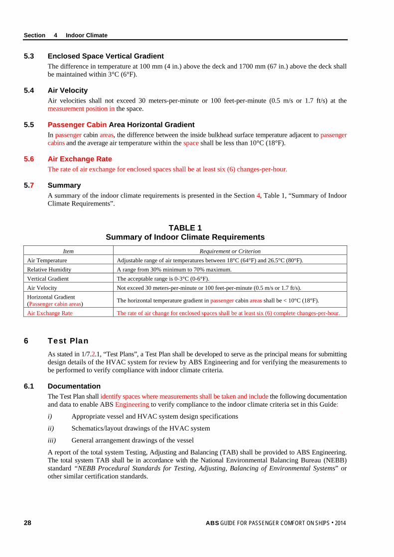
Section 4 Indoor Climate
28 ABS GUIDE FOR PASSENGER COMFORT ON SHIPS . 2014
5.3 Enclosed Space Vertical Gradient The difference in temperature at 100 mm (4 in.) above the deck and 1700 mm (67 in.) above the deck shall be maintained within 3°C (6°F).
5.4 Air Velocity Air velocities shall not exceed 30 meters-per-minute or 100 feet-per-minute (0.5 m/s or 1.7 ft/s) at the measurement position in the space.
5.5 Passenger Cabin Area Horizontal Gradient In passenger cabin areas, the difference between the inside bulkhead surface temperature adjacent to passenger cabins and the average air temperature within the space shall be less than 10°C (18°F).
5.6 Air Exchange Rate The rate of air exchange for enclosed spaces shall be at least six (6) changes-per-hour.
5.7 Summary A summary of the indoor climate requirements is presented in the Section 4, Table 1, “Summary of Indoor Climate Requirements”.
TABLE 1 Summary of Indoor Climate Requirements
Item Requirement or Criterion Air Temperature Adjustable range of air temperatures between 18°C (64°F) and 26.5°C (80°F). Relative Humidity A range from 30% minimum to 70% maximum. Vertical Gradient The acceptable range is 0-3°C (0-6°F). Air Velocity Not exceed 30 meters-per-minute or 100 feet-per-minute (0.5 m/s or 1.7 ft/s). Horizontal Gradient (Passenger cabin areas) The horizontal temperature gradient in passenger cabin areas shall be < 10°C (18°F).
Air Exchange Rate The rate of air change for enclosed spaces shall be at least six (6) complete changes-per-hour.
6 Test Plan As stated in 1/7.2.1, “Test Plans”, a Test Plan shall be developed to serve as the principal means for submitting design details of the HVAC system for review by ABS Engineering and for verifying the measurements to be performed to verify compliance with indoor climate criteria.
6.1 Documentation The Test Plan shall identify spaces where measurements shall be taken and include the following documentation and data to enable ABS Engineering to verify compliance to the indoor climate criteria set in this Guide:
i) Appropriate vessel and HVAC system design specifications
ii) Schematics/layout drawings of the HVAC system
iii) General arrangement drawings of the vessel
A report of the total system Testing, Adjusting and Balancing (TAB) shall be provided to ABS Engineering. The total system TAB shall be in accordance with the National Environmental Balancing Bureau (NEBB) standard “NEBB Procedural Standards for Testing, Adjusting, Balancing of Environmental Systems” or other similar certification standards.
Section 4 Indoor Climate
ABS GUIDE FOR PASSENGER COMFORT ON SHIPS . 2014 29
6.2 Test Personnel The Test Plan shall provide information about the Testing Specialist who will be conducting the test and their approval and certification in accordance with Appendix 2, “Procedural Requirements for ABS Recognized Ambient Environmental Testing Specialists”.
6.3 Test Conditions The Test Plan shall detail the conditions under which the tests will be performed. Details about test conditions are given in 4/7.3, “Test Conditions”.
6.4 Measurement Locations The Test Plan shall document, in detail, on appropriate drawings, all passenger spaces or areas where measurements will be taken. Details on selecting measurement locations and determining transducer positions are provided in 4/7.4, “Measurement Locations”.
6.5 Data Acquisition and Instruments The Test Plan shall provide information regarding the methods and instrumentation to be used for measurement and data collection. Instrumentation specification details shall include type of instruments to be used, accuracy, response time, calibration and sensitivity. More details on data acquisition and instruments are provided in 4/7.2, “Data Acquisition and Instruments”.
6.6 Data Analysis The Test Plan shall provide information regarding the methods, software and instrumentation to be used for data analysis.
6.7 Test Schedule The Test Plan shall provide information regarding the proposed test schedule.
7 Test Requirements
7.1 General Indoor climate measurements shall be in accordance with the procedures of ANSI/ASHRAE 55a and ANSI/ASHRAE 15. When the procedures described in this Guide deviate from those in ANSI/ASHRAE 55a and ANSI/ASHRAE 15, the more stringent requirement shall take precedence.
7.2 Data Acquisition and Instruments The thermal measurement instrumentation shall meet or exceed the minimum characteristics of instruments for measuring physical quantities characterizing an environment specified in ISO 7726.
The following quantities shall be measured in each of the spaces or zones identified in the Test Plan and the results noted in the Indoor Climate Test Report:
i) Air temperature
ii) Relative humidity
iii) Air velocity
iv) Vertical gradient
v) Horizontal gradient (in passenger cabin spaces only).
The air temperature and humidity measurements shall be made at least every five (5) minutes for a minimum period of one (1) hour. The minimum, maximum and average values for the 1-hour period shall be reported for each space measured. Note: Data loggers are a type of device that can be left unattended to capture data. These type devices have been proven
effective in gathering temperature and humidity values.
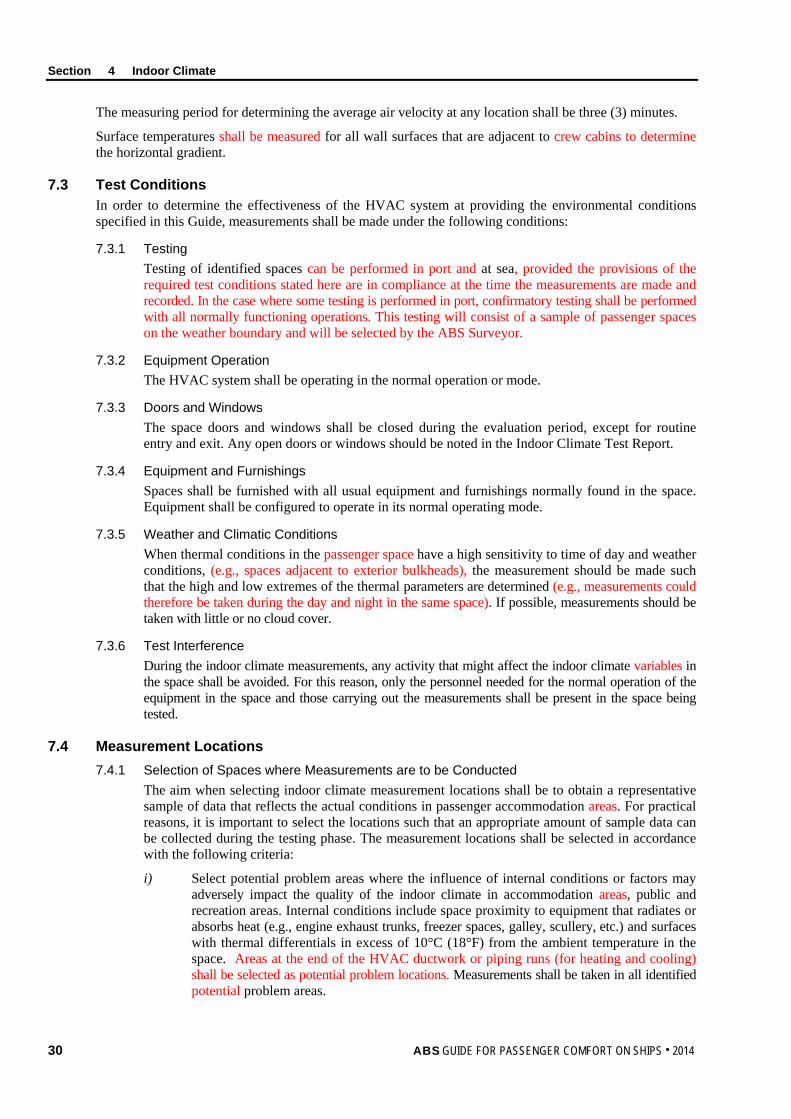
Section 4 Indoor Climate
30 ABS GUIDE FOR PASSENGER COMFORT ON SHIPS . 2014
The measuring period for determining the average air velocity at any location shall be three (3) minutes.
Surface temperatures shall be measured for all wall surfaces that are adjacent to crew cabins to determine the horizontal gradient.
7.3 Test Conditions In order to determine the effectiveness of the HVAC system at providing the environmental conditions specified in this Guide, measurements shall be made under the following conditions:
7.3.1 Testing Testing of identified spaces can be performed in port and at sea, provided the provisions of the required test conditions stated here are in compliance at the time the measurements are made and recorded. In the case where some testing is performed in port, confirmatory testing shall be performed with all normally functioning operations. This testing will consist of a sample of passenger spaces on the weather boundary and will be selected by the ABS Surveyor.
7.3.2 Equipment Operation The HVAC system shall be operating in the normal operation or mode.
7.3.3 Doors and Windows The space doors and windows shall be closed during the evaluation period, except for routine entry and exit. Any open doors or windows should be noted in the Indoor Climate Test Report.
7.3.4 Equipment and Furnishings Spaces shall be furnished with all usual equipment and furnishings normally found in the space. Equipment shall be configured to operate in its normal operating mode.
7.3.5 Weather and Climatic Conditions When thermal conditions in the passenger space have a high sensitivity to time of day and weather conditions, (e.g., spaces adjacent to exterior bulkheads), the measurement should be made such that the high and low extremes of the thermal parameters are determined (e.g., measurements could therefore be taken during the day and night in the same space). If possible, measurements should be taken with little or no cloud cover.
7.3.6 Test Interference During the indoor climate measurements, any activity that might affect the indoor climate variables in the space shall be avoided. For this reason, only the personnel needed for the normal operation of the equipment in the space and those carrying out the measurements shall be present in the space being tested.
7.4 Measurement Locations 7.4.1 Selection of Spaces where Measurements are to be Conducted
The aim when selecting indoor climate measurement locations shall be to obtain a representative sample of data that reflects the actual conditions in passenger accommodation areas. For practical reasons, it is important to select the locations such that an appropriate amount of sample data can be collected during the testing phase. The measurement locations shall be selected in accordance with the following criteria:
i) Select potential problem areas where the influence of internal conditions or factors may adversely impact the quality of the indoor climate in accommodation areas, public and recreation areas. Internal conditions include space proximity to equipment that radiates or absorbs heat (e.g., engine exhaust trunks, freezer spaces, galley, scullery, etc.) and surfaces with thermal differentials in excess of 10°C (18°F) from the ambient temperature in the space. Areas at the end of the HVAC ductwork or piping runs (for heating and cooling) shall be selected as potential problem locations. Measurements shall be taken in all identified potential problem areas.
Section 4 Indoor Climate
ABS GUIDE FOR PASSENGER COMFORT ON SHIPS . 2014 31
ii) Select potential problem areas where the influence of external ambient environmental conditions (e.g., sun, wind, precipitation, etc.) may adversely impact the quality of the indoor climate. These areas include accommodation areas, public and recreation areas which may be outboard or adjacent to the vessel’s hull. Measurements shall be taken in all identified problem areas.
iii) Where a single instance of one (1) type of space exists within the vessel (e.g., public lounge on a ferry), the location shall be selected for measurement.
iv) Where multiple instances of one (1) type of space exist (e.g., cabins/staterooms, dining areas, or public/recreation areas), a representative sample of at least twenty-five (25) percent of each type shall be selected for measurement. The worst case locations are to be considered part of the representative sample, if applicable.
All of these measurement locations must be selected at locations port, starboard, fore, amidships, and aft. The worst case locations can be considered part as the representative sample for passenger cabins and staterooms, if applicable.
7.4.2 Walkthrough Verification Inspection Locations All spaces normally occupied by passengers shall be subject to a walkthrough inspection by the ABS Surveyor. The number and locations of the walkthrough inspections will be determined by the ABS Surveyor. The purpose of the walkthrough verification is to subjectively assess the indoor climatic qualities. At the discretion of the ABS Surveyor, additional measurements may be required.
7.4.3 Transducer Measurement Positions For each space identified in the Test Plan, the transducer locations shall be standardized as follows:
i) Air temperature and relative humidity measuring instrumentation shall be set up approximately in the middle of the space to measure general space temperature and humidity levels. Air temperature shall be measured at approximately 100 mm (4 in.), 1100 mm (43 in.) and 1700 mm (67 in.) above the deck. Relative humidity shall be measured at a height of approximately 1700 mm (67 in.) above the deck.
ii) Air velocity data shall be captured at approximately 100 mm (4 in.), 1100 mm (43 in.), and 1700 mm (67 in.) above the deck in spaces where passengers will be lying, seated, or standing for twenty (20) minutes or longer, as applicable (to assure air velocity is not excessive). This measurement should be taken in the center of the space. Air velocity only needs to be measured once per testing location.
iii) Wall surface temperatures in passenger cabin spaces shall be captured at approximately 300 mm (12 in.) above the mattress. Inside wall surface temperatures shall be captured from all walls surrounding berthing location of approximately 1100 mm (43 in.) from the deck on all the wall surfaces.
8 Test Report As stated in 1/7.2.2, “Test Reports”, a Test Report shall be submitted to the ABS Surveyor to determine whether the indoor climate levels meet the criteria and whether this part of the notation requirement has been met. The details listed in the following paragraphs shall be provided in the Indoor Climate Test Report.
8.1 Test Details The following details shall be provided for each period of testing:
i) Vessel latitude and longitude coordinates during testing
ii) Weather conditions and meteorological data (i.e., wind speed and direction, ambient outdoor air temperature, outdoor humidity, barometric pressure) at the onset of every data collection period and at intervals of every four (4) hours (if needed) during any data collection period. Weather conditions shall also be reported at the end of each data collection period.
iii) Any indications of abnormal activities or conditions during the test that might skew results.
Section 4 Indoor Climate
32 ABS GUIDE FOR PASSENGER COMFORT ON SHIPS . 2014
8.2 Transducer Measurement Positions Actual measurement locations and transducer positions shall be indicated on appropriate drawings.
8.3 Measurement Equipment Details Details of measuring and analysis equipment (e.g., manufacturer, type and serial number, accuracy, sampling frequency and resolution) shall be provided.
Copies of the relevant instrumentation reference calibration certificates, together with the results of field setup and calibration checks before and after the field tests, shall be provided.
8.4 Results The following results, per measurement location and sample period as appropriate for notation, shall be provided in table format:
i) Measurement position
ii) Number of people present in the space at time of measurement
iii) Measurement period
iv) Time at start and end of measurement
v) Air temperature (minimum, maximum and average) at 100 mm (4 in.) above deck
vi) Air temperature (minimum, maximum and average) at 1100 mm (43 in.) above deck
vii) Air temperature (minimum, maximum and average) at 1700 mm (67 in.) above deck
viii) Relative humidity (minimum, maximum and average) at 1700 mm (67 in.) above deck
ix) Air velocity at 100, 1100 and 1700 mm (4, 43, and 67 in.) above deck at measurement positions
x) Vertical gradient (Average air temperature at 1700 mm (67 in.) minus average air temperature at 100 mm (4 in.) above deck)
xi) Horizontal gradient (Side wall surface temperature in passenger cabin spaces minus average air temperature at 1100 mm (43 in.) above deck)
xii) Wind speed and direction, ambient outdoor air temperature, outdoor humidity, and barometric pressure corresponding to indoor measurement periods
For all the remaining spaces that were checked through walkthrough verification inspection and spot check measurements, the following information shall be provided:
i) Name and number of space
ii) Walkthrough inspection observations
iii) Measurement results, if necessary
8.5 Deviations All deviations from the approved Test Plan shall be reported.
8.6 Surveyor Witnessing Documentation The equipment calibration and data collection process of the indoor climate tests shall be witnessed by an ABS Surveyor. The ABS Surveyor shall provide documentation stating whether all steps of the indoor climate testing were completed to their satisfaction. A copy of the witnessing document shall be given to the person conducting the testing, for insertion into the final Indoor Climate Test Report. The original shall be retained for ABS’ files.
9 Results The Indoor Climate Test Report and test results shall be reviewed by the ABS Surveyor against the appropriate COMF and COMF+ criteria for notation confirmation.
ABS GUIDE FOR PASSENGER COMFORT ON SHIPS . 2014 33
S e c t i o n 5 : L i g h t i n g
S E C T I O N 5 Lighting
1 Background The lighting of passenger spaces should facilitate visual comfort, support passenger activities appropriately and aid in the creation of an appropriate visual environment. Lighting design involves integrating these aspects to provide adequate illuminance for the comfort and well-being of passengers as well as for the various leisure activities passengers will be involved in on board vessels.
The selection of appropriate illuminance levels for specific tasks and passenger spaces is an important consideration in the design of lighting systems. There is a difference of opinion as to what levels of light may be considered best for visual tasks. Since illuminance recommendations are generally consensus values, for any task a range of illuminances may apply.
Visual tasks encountered on vessels vary and lighting provided can influence ability to see and perform those tasks. Some vision and lighting considerations include task duration, visual fatigue, task criticality, veiling reflections, shadows, and abilities of the observer. The presence of glare is a concern and is often difficult to identify, measure, and assess. Glare is often transient (based on factors such as the direction of the sun to illuminated components or from the placement of lighting fixtures) and therefore difficult to anticipate. As part of lighting data collection, glare shall be subjectively evaluated jointly by the Testing Specialist and the attending ABS Surveyor witnessing the collection of lighting data. These assessments shall be made as a part of the activities discussed in 5/7.4.2, “Walkthrough Verification Inspection Locations”.
Measurement of ambient lighting need only be performed once during transit or at pier side when all external light sources can be blocked out.
2 Scope This Section provides criteria for assessing the illuminance levels of general lighting and activity (task) lighting on vessels. The main objective of the assessment is to determine whether the various lighting systems comply with minimum standards to facilitate passenger comfort and well-being as well as accommodate passenger activities in accommodation areas and recreation spaces.
Lighting criteria are based on currently available objective standards and research data. Compliance with this Section is a prerequisite for the Comfort (COMF) or Comfort Plus (COMF+) notation confirmation.
3 Terminology Activity Lighting: Lighting provided to meet the illuminance requirements of a specific passenger activity. Activity lighting refers to the total illuminance requirement that may be obtained by supplementary lighting provided in addition to the general illuminance.
Activity Plane: The horizontal, vertical, or inclined plane in which the visual activity is performed. If no information is available, the activity plane may be considered to be the horizontal and at 750 mm (29.5 in.) above the deck for seated activities and 1000 mm (39.5 in.) for standing activities.
Disability Glare: Glare which reduces the ability to perform a visual task.
Discomfort Glare: Glare which produces viewer discomfort, but which does not significantly interfere with visual task performance or visibility.
General Lighting: Lighting designed to provide a substantially uniform level of illuminance throughout an area, exclusive of any provision for special, localized activity requirements. Such lighting should be provided by fixed luminaires.
Section 5 Lighting
34 ABS GUIDE FOR PASSENGER COMFORT ON SHIPS . 2014
Glare: The discomfort or impairment of vision experienced when parts of the visual field are excessively bright in relation to the general surroundings.
Illuminance: The luminous flux density at a surface (or the amount of light falling on an object or surface), i.e., the luminous flux incident-per-unit area. Illuminance is measured in units of Lux (lm/m2) or foot-candles (fc; lm/ft2). One foot-candle equals 10.76 Lux.
Luminaire: A complete lighting unit consisting of a lamp(s) together with the parts designed to distribute the light, to position and protect the lamp and to connect the lamp to the power supply.
Luminance: The photometric brightness of an illuminated surface (or the amount of light emitted or reflected from the surface). The SI unit of luminance is candela-per-square meter (cd/m2).
Luminous Flux: The light emitted by a source, or received by a surface and indicates the intensity of a source. Flux is expressed in lumens.
Lux: a unit of illumination, equivalent to 0.0929 foot-candle and equal to the illumination produced by luminous flux of one lumen falling perpendicularly on a surface one meter square. Also called meter-candle. Reference Calibration: Calibration of a measuring instrument, conducted by an accredited Testing and Calibration Laboratory, with traceability to a national or international standard.
4 Associated Documentation The following documents provide details about Test Plan preparation, test measurement procedures, and/or Test Reporting:
• ISO 8995:2000 (CIES 008/E), Lighting of indoor work places.
5 Criteria The lighting criteria for the Comfort (COMF and COMF+) notations are provided in Section 5, Table 1, “Lighting Criteria for Passenger Spaces”.
For lighting, the criteria for COMF and COMF+ are the same. In this Section, general lighting and activity (task) lighting requirements are provided for passenger activities and accommodation areas and recreation spaces normally encountered on passenger vessels. The lighting levels provided in Section 5, Table 1 are for new lamps. Emergency lighting is covered in SOLAS and IMO Resolutions and was not considered in the selection of the lighting levels provided in this Guide.
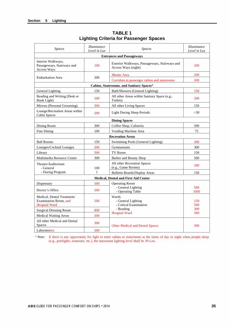
Section 5 Lighting
ABS GUIDE FOR PASSENGER COMFORT ON SHIPS . 2014 35
TABLE 1 Lighting Criteria for Passenger Spaces
Spaces Illuminance Level in Lux Spaces Illuminance
Level in Lux Entrances and Passageways
Interior Walkways, Passageways, Stairways and Access Ways
100 Exterior Walkways, Passageways, Stairways and Access Ways (night) 100
Embarkation Area 200 Muster Area 200 Corridors in passenger cabins and staterooms 100
Cabins, Staterooms, and Sanitary Spaces* General Lighting 150 Bath/Showers (General Lighting) 150 Reading and Writing (Desk or Bunk Light) 500 All other Areas within Sanitary Space (e.g.,
Toilets) 200
Mirrors (Personal Grooming) 500 All other Living Spaces 150 Lounge/Recreation Areas within Cabin Spaces 200 Light During Sleep Periods <30
Dining Spaces Dining Room 300 Coffee Shop, Cafeteria 500 Fine Dining 100 Vending Machine Area 75
Recreation Areas Ball Rooms 150 Swimming Pools (General Lighting) 300 Lounges/Cocktail Lounges 200 Gymnasiums 300 Library 500 TV Room 150 Multimedia Resource Center 300 Barber and Beauty Shop 500
Theater/Auditorium - General - During Program
100 1
All other Recreation Spaces (e.g., Game Rooms) 200
Bulletin Boards/Display Areas 150 Medical, Dental and First Aid Center
Dispensary 500 Operating Room - General Lighting - Operating Table
500 1000 Doctor’s Office 500
Medical, Dental Treatment/ Examination Room, and Hospital Ward
500 Wards - General Lighting - Critical Examination - Reading Hospital Ward
150 500 300 500
Surgical Dressing Room 800 Medical Waiting Areas 200 All other Medical and Dental Spaces 300
Other Medical and Dental Spaces 300 Laboratories 500
* Note: If there is any opportunity for light to enter cabins or staterooms at the times of day or night when people sleep (e.g., portlights, transoms, etc.), the maximum lighting level shall be 30 Lux.
Section 5 Lighting
36 ABS GUIDE FOR PASSENGER COMFORT ON SHIPS . 2014
6 Test Plan As stated in 1/7.2.1, “Test Plans”, a Test Plan shall be developed to serve as the principle means for submitting design details of the lighting system for review by ABS Engineering and for verifying the measurements to be performed to verify compliance with lighting criteria. The Test Plan shall include the following:
6.1 Documentation The Test Plan shall include appropriate design information and layout drawings showing the hull outline, bulkheads, access routes, location of luminaires, outlines of major furniture and equipment and the space name and number. The drawings shall be to a scale and sized to permit the scaling of survey points (required by 5/7.4, “Measurement Locations”) and lighting equipment and the recording of illuminance and other relevant data.
6.2 Test Personnel The Test Plan shall provide information about the Testing Specialist who will be conducting the test and their approval and certification in accordance with Appendix 2, “Procedural Requirements for ABS Recognized Ambient Environmental Testing Specialists”.
6.3 Test Conditions The Test Plan shall detail the conditions under which the tests will be performed. Details about test conditions are given in 5/7.3, “Test Conditions”.
6.4 Measurement Locations The Test Plan shall document, in detail, on appropriate drawings, all spaces or areas where measurements will be taken. In addition, measurement positions within these areas shall be indicated. Details on selecting measurement locations are provided in 5/7.4, “Measurement Locations”.
6.5 Data Acquisition and Instruments The Test Plan shall provide information regarding the methods and instrumentation to be used for measurement and data collection. Instrumentation specification details shall include type of instruments to be used, accuracy, calibration and sensitivity. More details on data acquisition and instruments are provided in 5/7.2, “Data Acquisition and Instruments”.
6.6 Data Analysis The Test Plan shall provide information regarding the methods used for data analysis.
6.7 Test Schedule The Test Plan shall provide information regarding the proposed test schedule.
7 Test Requirements
7.1 General Illuminance measurements shall be carried out as described below.
7.2 Data Acquisition and Instruments The illuminance meter (light meter) should meet the requirements specified in ISO 8995. This defines the instrumentation requirements for measuring white light.
Section 5 Lighting
ABS GUIDE FOR PASSENGER COMFORT ON SHIPS . 2014 37
7.3 Test Conditions The test conditions required for lighting measurements shall be in accordance with the following Subparagraphs.
7.3.1 Location Lighting measurements may be taken in port, at sea, or both, since the measurements are not dependent on vessel operation. If testing is done in port, power during testing shall come from the vessel not the port.
7.3.2 Spaces with Windows/Portholes In spaces with windows or portholes where the minimum lighting level should be provided by artificial light sources only, lighting measurements shall be taken after dark, or during the day provided all natural lighting is blocked out.
7.3.3 Spaces without Windows/Portholes Interior spaces with no windows or portholes can be measured during daylight hours.
7.3.4 Stray Light Stray light (e.g., deck lighting and moonlight) shall be capable of being masked out as far as practicable. Where it is not possible, measurements of stray light, at appropriate positions, with all lights turned off, shall be obtained. These readings shall then be deducted from readings taken at the same positions, with the lighting turned on, to determine illuminance from the lighting.
7.3.5 Light for Sleep Lighting measurements shall be taken in cabins and staterooms with all cabin and stateroom lights turned off and curtains, shutters, etc., closed.
7.3.6 Test Interference During the lighting measurements, shadows on the light meter caused by any kind of human activity shall be avoided. For this reason, only the personnel needed for the normal operation of the equipment in the space and those carrying out the measurements shall be present in the space being tested.
Doors and windows shall be closed, except where they are normally left open (such as the lee side door of the navigation bridge, which may normally be open). Any open doors or windows shall be noted in the Lighting Test Report. Spaces shall be furnished with all usual equipment and furnishings normally found in the space.
7.3.7 External (Deck) Lighting External areas shall be tested on dark evenings without contribution of light to the deck areas from shore lights. Light measurements taken for these locations shall result from lighting systems aboard (excepting star and moon light contributions).
7.4 Measurement Locations 7.4.1 Selection of Spaces where Measurements are to be Conducted
The aim when selecting lighting measurement locations shall be to obtain a representative sample of data that represents the actual conditions in passenger spaces in Section 5, Table 1, “Lighting Criteria for Passenger Spaces”. For practical reasons, it is important to select the locations such that an appropriate amount of sample data can be collected during the testing phase. The measurement locations shall be selected in accordance with the following criteria:
i) Select problem areas based on the potential for excessive external illumination (daylight) into the space (e.g., dining areas, lounges, etc.). Measurements shall be taken in all identified problem areas.
ii) Select potential problem areas based on the positioning of luminaires in the space as indicated on the drawings (e.g., uneven spacing of luminaires resulting in non-uniform illuminance levels and dimly lit areas). Measurements shall be taken in all identified areas.
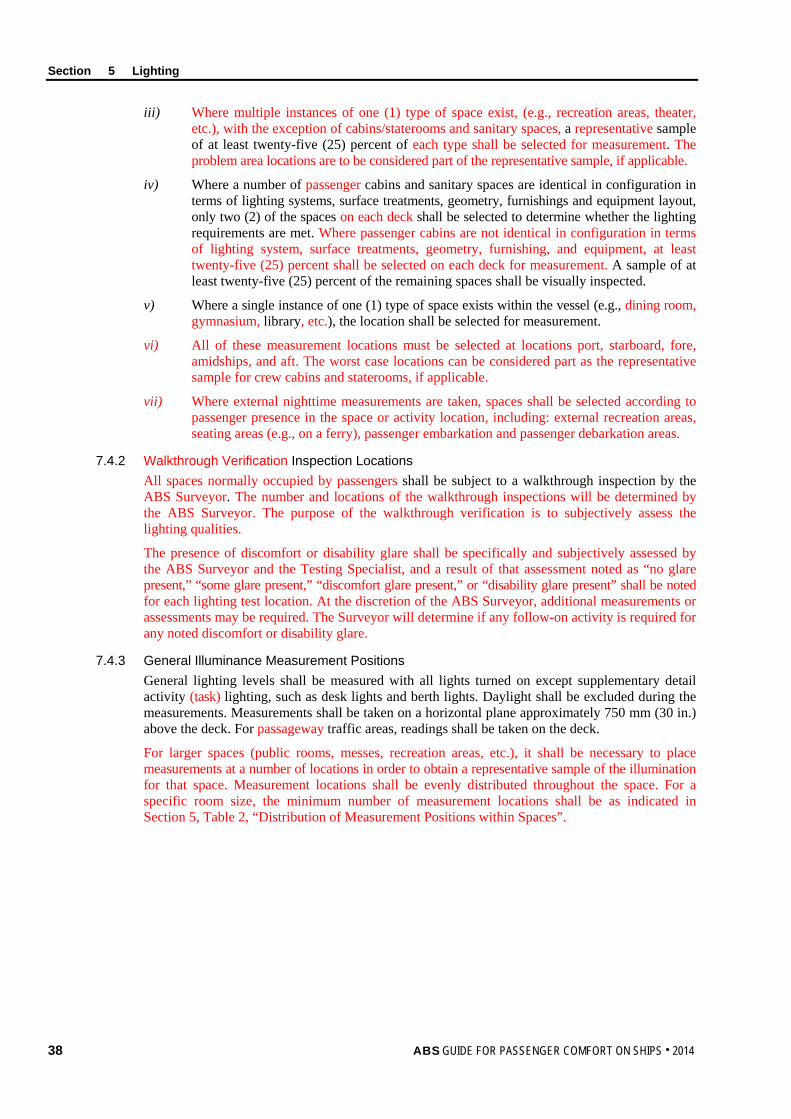
Section 5 Lighting
38 ABS GUIDE FOR PASSENGER COMFORT ON SHIPS . 2014
iii) Where multiple instances of one (1) type of space exist, (e.g., recreation areas, theater, etc.), with the exception of cabins/staterooms and sanitary spaces, a representative sample of at least twenty-five (25) percent of each type shall be selected for measurement. The problem area locations are to be considered part of the representative sample, if applicable.
iv) Where a number of passenger cabins and sanitary spaces are identical in configuration in terms of lighting systems, surface treatments, geometry, furnishings and equipment layout, only two (2) of the spaces on each deck shall be selected to determine whether the lighting requirements are met. Where passenger cabins are not identical in configuration in terms of lighting system, surface treatments, geometry, furnishing, and equipment, at least twenty-five (25) percent shall be selected on each deck for measurement. A sample of at least twenty-five (25) percent of the remaining spaces shall be visually inspected.
v) Where a single instance of one (1) type of space exists within the vessel (e.g., dining room, gymnasium, library, etc.), the location shall be selected for measurement.
vi) All of these measurement locations must be selected at locations port, starboard, fore, amidships, and aft. The worst case locations can be considered part as the representative sample for crew cabins and staterooms, if applicable.
vii) Where external nighttime measurements are taken, spaces shall be selected according to passenger presence in the space or activity location, including: external recreation areas, seating areas (e.g., on a ferry), passenger embarkation and passenger debarkation areas.
7.4.2 Walkthrough Verification Inspection Locations All spaces normally occupied by passengers shall be subject to a walkthrough inspection by the ABS Surveyor. The number and locations of the walkthrough inspections will be determined by the ABS Surveyor. The purpose of the walkthrough verification is to subjectively assess the lighting qualities.
The presence of discomfort or disability glare shall be specifically and subjectively assessed by the ABS Surveyor and the Testing Specialist, and a result of that assessment noted as “no glare present,” “some glare present,” “discomfort glare present,” or “disability glare present” shall be noted for each lighting test location. At the discretion of the ABS Surveyor, additional measurements or assessments may be required. The Surveyor will determine if any follow-on activity is required for any noted discomfort or disability glare.
7.4.3 General Illuminance Measurement Positions General lighting levels shall be measured with all lights turned on except supplementary detail activity (task) lighting, such as desk lights and berth lights. Daylight shall be excluded during the measurements. Measurements shall be taken on a horizontal plane approximately 750 mm (30 in.) above the deck. For passageway traffic areas, readings shall be taken on the deck.
For larger spaces (public rooms, messes, recreation areas, etc.), it shall be necessary to place measurements at a number of locations in order to obtain a representative sample of the illumination for that space. Measurement locations shall be evenly distributed throughout the space. For a specific room size, the minimum number of measurement locations shall be as indicated in Section 5, Table 2, “Distribution of Measurement Positions within Spaces”.
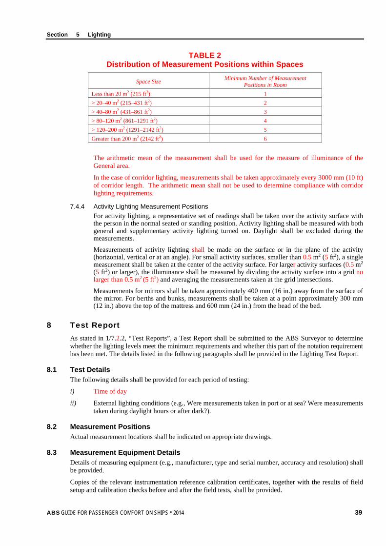
Section 5 Lighting
ABS GUIDE FOR PASSENGER COMFORT ON SHIPS . 2014 39
TABLE 2 Distribution of Measurement Positions within Spaces
Space Size Minimum Number of Measurement Positions in Room
Less than 20 m2 (215 ft2) 1 > 20–40 m2 (215–431 ft2) 2 > 40–80 m2 (431–861 ft2) 3 > 80–120 m2 (861–1291 ft2) 4 > 120–200 m2 (1291–2142 ft2) 5 Greater than 200 m2 (2142 ft2) 6
The arithmetic mean of the measurement shall be used for the measure of illuminance of the General area.
In the case of corridor lighting, measurements shall be taken approximately every 3000 mm (10 ft) of corridor length. The arithmetic mean shall not be used to determine compliance with corridor lighting requirements.
7.4.4 Activity Lighting Measurement Positions For activity lighting, a representative set of readings shall be taken over the activity surface with the person in the normal seated or standing position. Activity lighting shall be measured with both general and supplementary activity lighting turned on. Daylight shall be excluded during the measurements.
Measurements of activity lighting shall be made on the surface or in the plane of the activity (horizontal, vertical or at an angle). For small activity surfaces, smaller than 0.5 m2 (5 ft2), a single measurement shall be taken at the center of the activity surface. For larger activity surfaces (0.5 m2 (5 ft2) or larger), the illuminance shall be measured by dividing the activity surface into a grid no larger than 0.5 m2 (5 ft2) and averaging the measurements taken at the grid intersections.
Measurements for mirrors shall be taken approximately 400 mm (16 in.) away from the surface of the mirror. For berths and bunks, measurements shall be taken at a point approximately 300 mm (12 in.) above the top of the mattress and 600 mm (24 in.) from the head of the bed.
8 Test Report As stated in 1/7.2.2, “Test Reports”, a Test Report shall be submitted to the ABS Surveyor to determine whether the lighting levels meet the minimum requirements and whether this part of the notation requirement has been met. The details listed in the following paragraphs shall be provided in the Lighting Test Report.
8.1 Test Details The following details shall be provided for each period of testing:
i) Time of day
ii) External lighting conditions (e.g., Were measurements taken in port or at sea? Were measurements taken during daylight hours or after dark?).
8.2 Measurement Positions Actual measurement locations shall be indicated on appropriate drawings.
8.3 Measurement Equipment Details Details of measuring equipment (e.g., manufacturer, type and serial number, accuracy and resolution) shall be provided.
Copies of the relevant instrumentation reference calibration certificates, together with the results of field setup and calibration checks before and after the field tests, shall be provided.
Section 5 Lighting
40 ABS GUIDE FOR PASSENGER COMFORT ON SHIPS . 2014
8.4 Results The following results, per space, shall be provided in table format:
i) Name and number of space
ii) Activity areas (if any) in space
iii) Average lighting level for general lighting
iv) Average lighting level for activity lighting on each activity surface or plane in space
v) Corridor lighting measurements (if applicable)
vi) Presence of glare at specific activity surfaces within the space and any follow-up activity requirements
For all the remaining spaces that were checked through walkthrough verification inspection and spot check measurements, the following information shall be provided: i) Name and number of space
ii) Walkthrough inspection observations
iii) Measurement results, if necessary
8.5 Deviations All deviations from the approved Test Plan shall be reported.
8.6 Surveyor Witnessing Documentation An ABS Surveyor shall witness the equipment calibration and data collection process of the lighting tests. The ABS Surveyor shall provide documentation stating whether all steps of the lighting testing were completed to their satisfaction. A copy of the witnessing document shall be given to the person conducting the testing, for insertion into the final Lighting Test Report. The original shall be retained for ABS’ files.
9 Results The Lighting Test Report and test results shall be reviewed by the ABS Surveyor against the lighting criteria for notation confirmation.
ABS GUIDE FOR PASSENGER COMFORT ON SHIPS . 2014 41
A p p e n d i x 1 : R e f e r e n c e s
A P P E N D I X 1 References
1 General References 1 American Bureau of Shipping. Guide for Building and Classing Yachts. Houston, TX.
2 American Bureau of Shipping. Guide for Crew Habitability on Ships. Houston, TX.
3 American Bureau of Shipping. Guide for Crew Habitability on Workboats. Houston, TX.
4 American Bureau of Shipping. Rules for Building and Classing Steel Vessels. Houston, TX.
5 American Bureau of Shipping. Rules for Materials and Welding: Aluminum and Fiber Reinforced Plastics. Houston, TX.
2 Vibration References 1 British Standards Institution. (1987). Guide to measurement and evaluation of human exposure to
whole-body mechanical vibration and repeated shock (BS 6841: 1987). London: Author.
2 Griffin M. J. (1990). Handbook of human vibration. London: Academic Press.
3 International Organization for Standardization. (2000). Mechanical Vibration and Shock – Guidelines for the Measurement, Reporting and Evaluation of Vibration with Regard to Habitability on Passenger and Merchant Ships. (ISO 6954:2000). Geneva.
4 International Organization for Standardization. (2003). Mechanical Vibration and Shock – Evaluation of Human Exposure to Whole Body Vibration – Part 2, Vibration in Buildings. (ISO 2631-2:2003). Geneva.
5 International Organization for Standardization. (1996). Acoustics – Measurement of noise shipboard vessels (ISO 2923: 1996). Geneva: Author.
6 International Organization for Standardization. (2008) Mechanical Vibration on Ships – Part 2: Measurement of Structural Vibration (ISO 20283-2:2008). Geneva.
7 International Organization for Standardization. (1998). Mechanical mounting of accelerometers for measuring mechanical vibration and shock (ISO 5348: 1998(E)). Geneva: Author.
8 International Organization for Standardization. (2005). Human response to vibration – Measuring instrumentation (ISO 8041: 2005). Geneva: Author.
9 World Meteorological Organization. (1995). International Codes Vol I.1 Part A Alphanumeric Codes. Boston, MA: American Meteorological Society.
3 Noise References 1 International Electrotechnical Commission. (2004). Electroacoustics – Sound Level Meters – Part 1:
Specifications (International Standard IEC 61672-1). Geneva: IEC Central Office.
2 International Electrotechnical Commission. (2000). Integrating-averaging sound level meters (International Standard IEC 60804(2000-10)). Geneva: IEC Central Office.
3 International Maritime Organization. (1981). Code on noise levels on board ships (IMO Resolution A.468(XII)). London.
Appendix 1 References
42 ABS GUIDE FOR PASSENGER COMFORT ON SHIPS . 2014
4 International Organization for Standardization. (1996). Acoustics – Measurement of noise on-board vessels (ISO 2923: 1996). Geneva.
5 Kryter, K.D. (1994). The handbook of hearing and the effects of noise: Physiology, psychology and public health. San Diego, CA: Academic Press.
6 World Meteorological Organization. (1995). International Codes Vol I.1 Part A Alphanumeric Codes. Boston, MA: American Meteorological Society.
4 Indoor Climate References 1 American National Standards Institute. (2010). Thermal environmental conditions for human
occupancy (ANSI/ASHRAE 55a-2010). Atlanta, GA: The American Society of Heating, Refrigerating and Air Conditioning Engineers, Inc.
2 International Organization for Standardization. (1998). Ergonomics of the thermal environment – Instruments for measuring physical quantities (ISO 7726: 1998 (E)). Geneva.
3 National Environmental Balancing Bureau. (2005). NEBB Procedural standards for testing, adjusting, balancing of environmental systems. Gaithersburg, MD.
4 American National Standards Institute. (2010). Practices for Measuring, Testing, Adjusting, and Balancing Shipboard HVAC&R Systems. (ANSI/ASHRAE 15-2010). Atlanta, GA: The American Society of Heating, Refrigerating and Air Conditioning Engineers, Inc.
5 International Organization for Standardization. (1998). Ergonomics of the thermal environment – Instruments for measuring physical quantities (ISO 7726: 1998 (E)). Geneva.
5 Lighting References 1 International Organization for Standardization. (2000). Lighting of Indoor Work Places (ISO
8995:2000). Geneva
ABS GUIDE FOR PASSENGER COMFORT ON SHIPS . 2014 43
Appendix 2: Procedural Requirements for ABS Recognized Ambient Environmental Testing Specialists
A P P E N D I X 2 Procedural Requirements for ABS Recognized Ambient Environmental Testing Specialists
1 Terminology ABS Recognized Ambient Environmental Testing Specialists: Companies providing test or measurement services on behalf of the Owner of a vessel or shipyard for the purposes of meeting ABS Passenger Comfort (COMF, COMF+), notation requirements. Approval of the Testing Specialist for passenger ships may also allow for testing and measurement services for other ABS Habitability, Comfort, and MLC notations:
• HAB, HAB+, HAB++
• HAB(WB), HAB+(WB), HAB++(WB)
• HAB(OS), HAB+(OS), HAB++(OS)
• HAB(MODU), HAB+(MODU), HAB++(MODU)
• COMF(Y), COMFY+(Y)
• MLC-ACCOM, MLC-ACCOM(SPS), MLC-ACCOM(WB) Note that for COMF+ and COMF+(Y), motion sickness testing is required.
Calibration Checks: Field calibration of a measuring instrument, conducted before and after a field test, using a reference calibrated signal or through zero calibration.
Reference Calibration: Calibration of a measuring instrument, conducted by an accredited Testing and Calibration Laboratory, with traceability to a national or international standard.
2 Objective The objective of this procedure is to set basic standards for qualifying and certifying Testing Specialists performing ambient environmental testing and evaluation.
3 Application This procedure applies to the approval of Testing Specialists that provide the following ambient environment test services:
i) Whole-body Vibration measurements and analysis
ii) Noise measurements and analysis
iii) Indoor Climate measurement and analysis
iv) Lighting measurement and analysis.
General requirements concerning Testing Specialists are given in A2/4.2, “General Requirements”. Specific requirements for the test services listed above are in this Subsection A2/8, “Detailed Requirements by Ambient Environmental Aspect”.
Appendix 2 Procedural Requirements for ABS Recognized Ambient Environmental Testing Specialists
44 ABS GUIDE FOR PASSENGER COMFORT ON SHIPS . 2014
4 Procedure for Approval and Certification
4.1 Documentation Requirements The following documents are to be submitted to ABS for review:
i) An outline of the company (e.g., organization and management structure) including subsidiaries or subcontractors to be included in the approval/certification
ii) A list of company experience in the specific ambient environmental aspect
iii) A list of test personnel documenting training and experience in conducting tests within the relevant ambient environmental aspect and qualifications according to recognized national, international or industry standards, as applicable
iv) Description of equipment used for the measurement and analysis of the particular ambient environmental aspect for which approval is sought (e.g., calibration, accuracy, etc.)
The following documents will be reviewed during the initial approval audit (See A2/4.3, “Auditing of the Testing Specialist”):
i) A guide for operators of such equipment
ii) Training programs for test personnel
iii) Draft checklists and data recording sheets for recording results of the services referred to in Subsection A2/3, “Application”
iv) Quality Manual and/or documented procedures covering requirements in A2/4.5, “Quality Assurance System”
v) Evidence of approval/acceptance by certifying bodies, if any
vi) Information about other activities which may present a conflict of interest
vii) Record of customer claims and of corrective actions requested by certification bodies for the past year
viii) Where relevant, list and documentation of licenses granted by equipment’s manufacturer.
ix) Example Test Plan(s) for the ambient environmental quality for which approval is requested.
x) Example Test Reports
4.2 General Requirements 4.2.1 Extent of Approval
The Testing Specialist shall demonstrate, as required by A2/4.2.2 “Training of Personnel” through A2/4.2.9, “Reporting”, that they have the competence, quality control and quality assurance needed to perform the test and analysis services for which approval is sought.
4.2.2 Training of Personnel The Testing Specialist is responsible for the qualification and training of its personnel to a recognized national, international or industry standard as applicable. Where such standards do not exist, the Testing Specialist is to define standards for the training and qualification of its personnel relevant to the functions each is authorized to perform. The personnel shall also have adequate experience and be familiar with the operation of any necessary equipment.
4.2.3 Supervision The Testing Specialist shall provide supervision for all services provided. The responsible supervisor shall have had a minimum of two (2) years’ experience in supervising tests in the ambient environmental aspect for which the Testing Specialist is recognized.
Appendix 2 Procedural Requirements for ABS Recognized Ambient Environmental Testing Specialists
ABS GUIDE FOR PASSENGER COMFORT ON SHIPS . 2014 45
4.2.4 Personnel Records The Testing Specialist shall keep records of the recognized test personnel. The records shall contain information about formal education, training and experience for the ambient environmental test services for which they are recognized.
4.2.5 Equipment and Facilities The Testing Specialist shall have the necessary equipment and facilities for the ambient environmental aspect to be tested. A record of the equipment used for ambient environmental testing shall be kept. The record shall contain information about maintenance and calibration.
4.2.6 Procedures The Testing Specialist shall have documented work procedures covering all ambient environmental test services supplied.
4.2.7 Subcontractors The Testing Specialist shall give information of agreements and arrangements if any parts of the services provided are subcontracted. Particular emphasis shall be given to quality management by the Testing Specialist in following-up of such subcontracts. Subcontractors providing anything other than subcontracted personnel or equipment shall also meet the requirements of A2/4.2, “General Requirements” and A2/4.5, “Quality Assurance System”.
4.2.8 Verification The Testing Specialist shall verify that the services provided are carried out in accordance with approved procedures.
4.2.9 Reporting The report shall be prepared in a form acceptable to ABS as outlined within this Guide. The report shall include a copy of the Certificate of Approval.
4.3 Auditing of the Testing Specialist Upon reviewing the submitted documents with satisfactory result, the Testing Specialist shall be audited for the initial certification process and then every three (3) years in order to ascertain that the Testing Specialist is duly organized and managed in accordance with the submitted documents and that it is considered capable of conducting the test services for which approval/certification is sought.
4.4 Certification Certification is conditional on a practical demonstration to ABS or its agent of the specific ambient environmental test service performance as well as a sample of a satisfactory report.
4.5 Quality Assurance System The Testing Specialist shall have a documented system covering at least the following:
i) Operating instructions for the test equipment
ii) Maintenance and reference calibration of equipment
iii) Training programs for test personnel
iv) Supervision and verification to verify compliance with test procedures
v) Recording and reporting of information
vi) Quality management of subsidiaries and sub-contractors
vii) Job preparation
viii) Periodic review of test process procedures, complaints, corrective actions and issuance maintenance and control of documents.
A documented Quality Assurance system complying with the applicable ISO 9000 standard or equivalent and including the above items would be considered acceptable.
Appendix 2 Procedural Requirements for ABS Recognized Ambient Environmental Testing Specialists
46 ABS GUIDE FOR PASSENGER COMFORT ON SHIPS . 2014
4.6 Testing Specialist Relations with the Test Equipment Manufacturer A company which works as a service station and conducts reference calibrations of equipment for a manufacturer (and is a Testing Specialist in this field) shall be assessed by the manufacturer(s) and nominated as their agent. The manufacturer shall verify that appropriate instruction manuals, material, etc., are available for the agent as well as verifying proper training of the agent’s technicians has occurred. Such Testing Specialists shall be recognized either on a case by case basis or as follows:
If a manufacturer of equipment (and Testing Specialist) applies for inclusion of its nominated agents and/or subsidiaries in the approval, then the manufacturer must have implemented a quality assurance system certified in accordance with the relevant ISO 9000 standard or equivalent. The manufacturer must have effective controls of its agents and/or subsidiaries and these agents/subsidiaries must have an equally effective quality control system complying with the relevant ISO 9000 or equivalent. Such approvals shall be based upon an evaluation of the quality assurance system implemented by the applicable company ISO 9000 or equivalent. ABS shall follow-up the adherence to this quality assurance system by performing audits on such agents or subsidiaries against the relevant ISO 9000 standard or equivalent.
5 Certificate of Approval Upon satisfactory completion of both the audit of the Testing Specialist and practical demonstration, ABS shall issue a Certificate of Approval stating that the Testing Specialist’s test and analysis service operation system has been found to be satisfactory and that the results of test and analysis services performed in accordance with that system may be accepted and utilized by ABS in making decisions affecting optional Habitability/Comfort classification notations. The Certificate shall clearly state the type and scope of services and any limitations or restrictions imposed. The Testing Specialist shall also be included in ABS’s records of recognized Testing Specialists.
Where several ambient environmental aspect measurements are conducted by a given company, each aspect is to be assessed and recognized except as specified in A2/4.6, “Testing Specialist Relations with the Test Equipment Manufacturer”.
5.1 Renewal The Certificate of Approval is subject to renewal or endorsement at intervals not exceeding three (3) years per Testing Specialist procedure. The renewal or endorsement shall be accomplished by verification through audits to ensure that approved conditions are maintained.
6 Alterations When any alteration to the certified test and analysis service operation system of the Testing Specialist is made, ABS is to be immediately notified. Re-audit may be required when deemed necessary by ABS.
7 Cancellation of Approval Approval may be cancelled in the following cases:
i) Where the service was improperly carried out or the results were improperly reported
ii) Where deficiencies are found in the recognized services of the Testing Specialist and appropriate corrective action is not taken
iii) Where the Testing Specialist fails to inform ABS of any alteration, as in Subsection A2/6, “Alterations”
iv) Where a renewal audit, if requested per A2/5.1, “Renewal”, has not been carried out
v) Where willful acts or omissions are ascertained.
ABS reserves the right to cancel the approval if any of these cases are met.
A Testing Specialist whose approval was cancelled may apply for re-approval provided the non-conformities, which resulted in cancellation, have been corrected and that ABS is able to confirm that the corrective action has been effectively implemented.
Appendix 2 Procedural Requirements for ABS Recognized Ambient Environmental Testing Specialists
ABS GUIDE FOR PASSENGER COMFORT ON SHIPS . 2014 47
8 Detailed Requirements by Ambient Environmental Aspect
8.1 Whole-body Vibration 8.1.1 Extent of Engagement
Whole-body vibration measurement Testing Specialists are engaged to conduct vibration measurements and analyses on board vessels.
8.1.2 Supervisor The supervisor shall:
i) be qualified to Level II according to a recognized national or international Nondestructive Testing (NDT) standard (ANSI/ASNT CP-189, ISO 9712 or EN 473) or
ii) be a Certified Industrial Hygienist (CIH) with experience in this ambient environmental aspect or
iii) have a documented history of at least two (2) years supervising vibration testing on board marine vessels.
The supervisor shall have sufficient knowledge of vessel structures and equipment, measurement and analysis of whole-body vibration according to BS 6841 and ISO 6954, to verify that test procedures are compliant with the required test conditions.
8.1.3 Test Personnel The test personnel carrying out the measurements shall:
i) be qualified to Level I according to a recognized national or international Nondestructive Testing (NDT) standard (ANSI/ASNT CP-189, ISO 9712 or EN 473) or
ii) have a documented history of experience in performing vibration environmental testing onboard marine vessels.
iii) have adequate knowledge of vessel structures and equipment.
8.1.4 Equipment ABS shall verify that the equipment to be used is in accordance with the applicable measurement standard. It shall be demonstrated to ABS that it is fit for the intended purpose.
8.1.5 Procedures Documented work procedures or test instructions are to contain, at a minimum, information about the following:
i) Test preparation
ii) Selection and identification of measurement locations
iii) Surface preparation
iv) Calibration checks
v) Testing methods
vi) Equipment handling
vii) Report preparation and content
viii) Method for handling previous results if subsequent calibration shows instruments to be out of tolerance.
8.1.6 Reporting The report shall be based on the instructions given in Subsection 3/8, “Test Report”.
Appendix 2 Procedural Requirements for ABS Recognized Ambient Environmental Testing Specialists
48 ABS GUIDE FOR PASSENGER COMFORT ON SHIPS . 2014
8.2 Noise 8.2.1 Extent of Engagement
Noise measurement Testing Specialists are engaged to conduct noise measurements and analyses on board vessels.
8.2.2 Supervisor The supervisor shall:
i) be qualified to Level II according to a recognized national or international Nondestructive Testing (NDT) standard (ANSI/ASNT CP-189, ISO 9712 or EN 473) or
ii) be a Certified Industrial Hygienist (CIH) with experience in this ambient environmental aspect or
iii) have a documented history of at least two (2) years supervising noise testing on board marine vessels.
The supervisor shall have sufficient knowledge of vessel structures, measuring equipment, ISO 2923, IEC 61672-1, and IEC 60804, to verify that test procedures are compliant with the required test conditions.
8.2.3 Test Personnel The test personnel carrying out the measurements shall:
i) be qualified to Level I according to a recognized national or international Nondestructive Testing (NDT) standard (ANSI/ASNT CP-189, ISO 9712 or EN 473) or
ii) have a documented history of experience in performing noise testing onboard marine vessels.
iii) have adequate knowledge of vessel structures and equipment.
8.2.4 Equipment ABS shall verify that the equipment to be used is in accordance with the applicable measurement standard. It shall be demonstrated to ABS that it is fit for the intended purpose.
8.2.5 Procedures Documented work procedures or test instructions are to contain, at a minimum, information about the following:
i) Test preparation
ii) Selection and identification of measurement locations
iii) Surface preparation
iv) Calibration checks
v) Testing methods
vi) Equipment handling
vii) Report preparation and content
viii) Method for handling previous results if subsequent calibration shows instruments to be out of tolerance.
8.2.6 Reporting The report shall be based on the instructions given in Subsection 4/8, “Test Report”.
Appendix 2 Procedural Requirements for ABS Recognized Ambient Environmental Testing Specialists
ABS GUIDE FOR PASSENGER COMFORT ON SHIPS . 2014 49
8.3 Indoor Climate 8.3.1 Extent of Engagement
Indoor climate measurement Testing Specialists are engaged to conduct indoor climate measurements and analyses on board vessels.
8.3.2 Supervisor The supervisor shall:
i) be qualified to Level II according to a recognized national or international Nondestructive Testing (NDT) standard (ANSI/ASNT CP-189, ISO 9712 or EN 473) or
ii) be a Certified Industrial Hygienist (CIH) with experience in this ambient environmental aspect or
iii) have a documented history of at least two (2) years supervising ambient environmental testing on board marine vessels.
The supervisor shall have sufficient knowledge of vessel structures, measuring equipment, ANSI/ASHRAE 15 and 55a as well as ISO 7726, to verify that test procedures are compliant with the required test conditions.
8.3.3 Test Personnel The test personnel carrying out the measurements shall:
i) be qualified to Level I according to a recognized national or international Nondestructive Testing (NDT) standard (ANSI/ASNT CP-189, ISO 9712 or EN 473) or
ii) have a documented history of experience in performing ambient environmental testing onboard marine vessels.
iii) have adequate knowledge of vessel structures and equipment.
8.3.4 Equipment ABS shall verify that the equipment to be used is in accordance with the applicable measurement standard. It shall be demonstrated to ABS that it is fit for the intended purpose.
8.3.5 Procedures Documented work procedures or test instructions are to contain, at a minimum, information about the following:
i) Test preparation
ii) Selection and identification of measurement locations
iii) Surface preparation, if applicable
iv) Testing methods
v) Equipment handling
vi) Report preparation and content
vii) Method for handling previous results if subsequent calibration shows instruments to be out of tolerance.
8.3.6 Reporting The report shall be based on the instructions given in Subsection 5/8, “Test Report”.
Appendix 2 Procedural Requirements for ABS Recognized Ambient Environmental Testing Specialists
50 ABS GUIDE FOR PASSENGER COMFORT ON SHIPS . 2014
8.4 Lighting 8.4.1 Extent of Engagement
Lighting measurement Testing Specialists are engaged to conduct illuminance measurements and analyses on board vessels.
8.4.2 Supervisor The supervisor shall:
i) be qualified to Level II according to a recognized national or international Nondestructive Testing (NDT) standard (ANSI/ASNT CP-189, ISO 9712 or EN 473) or
ii) be a Certified Industrial Hygienist (CIH) with experience in this ambient environmental aspect or
iii) have a documented history of at least two (2) years supervising ambient environmental testing on board marine vessels.
The supervisor shall have sufficient knowledge of vessel structures, measuring equipment and IESNA RP-12, to verify that test procedures are compliant with the required test conditions.
8.4.3 Test Personnel The test personnel carrying out the measurements shall:
i) be qualified to Level I according to a recognized national or international Nondestructive Testing (NDT) standard (ANSI/ASNT CP-189, ISO 9712 or EN 473) or
ii) have a documented history of experience in performing ambient environmental testing onboard marine vessels.
iii) have adequate knowledge of vessel structures and equipment.
8.4.4 Equipment ABS shall verify that the equipment to be used is in accordance with the applicable measurement standard. It shall be demonstrated to ABS that it is fit for the intended purpose.
8.4.5 Procedures Documented work procedures or test instructions are to contain, at a minimum, information about the following:
i) Test preparation
ii) Selection and identification of measurement locations
iii) Surface preparation
iv) Calibration checks
v) Testing methods
vi) Equipment handling
vii) Report preparation and content
viii) Method for handling previous results if subsequent calibration shows instruments to be out of tolerance.
8.4.6 Reporting The report shall be based on the instructions given in Subsection 5/8, “Test Report”.
ABS GUIDE FOR PASSENGER COMFORT ON SHIPS . 2014 51
A p p e n d i x 3 : A c r o n y m s a n d A b b r e v i a t i o n s
A P P E N D I X 3 Acronyms and Abbreviations
°C Degrees Celsius °F Degrees Fahrenheit ABS American Bureau of Shipping ANSI American National Standards Institute ASNT American Society of Non-destructive Testing ASTM American Society of Testing and Materials ASHRAE American Society of Heating, Refrigerating and Air Conditioning Engineers aw Multi-axis acceleration value axw The weighted root mean square acceleration values measured along the x-axis ayw The weighted root mean square acceleration values measured along the y-axis azw The weighted root mean square acceleration values measured along the z-axis
BS British Standard cd/m2 Candela-per-square meter CIH Certified Industrial Hygienist COMF Comfort notation COMF+ Comfort Plus notation dB(A) Decibels measured using the A weighted scale ed. Edition EN European Norms ft/s Feet-per-second fc Foot-candle ft Feet ft2 Square feet GFI Ground Fault Interrupter HVAC Heating, Ventilation and Air Conditioning Hz Hertz IEC International Electrotechnical Commission ILO International Labor Organization IMO International Maritime Organization in. Inch ISO International Organization for Standardization LAeq Equivalent continuous A weighted sound pressure level
lm/m2 Lumens-per-square meter lm/ft2 Lumens-per-square foot m Meter m2 Square meter m/s Meters-per-second m/s2 Meters-per-second squared
Appendix 3 Acronyms and Abbreviations
52 ABS GUIDE FOR PASSENGER COMFORT ON SHIPS . 2014
Max Maximum MCR Maximum Continuous Rating Min Minimum mm Millimeter MSDVZ Motion Sickness Dose Value
NDT Nondestructive Testing NEBB National Environmental Balancing Bureau NORSOK Norwegian Engineering Industries RH Relative humidity RMS Root-mean square SI International System of Units SOLAS Safety Of Life At Sea TAB Testing, Adjusting and Balancing TX Texas USA United States of America VDV Vibration Dose Value Wm Frequency weighting used to evaluate x, y, and z-axis vibration with respect to
comfort. WMO World Meteorological Organization
ABS GUIDE FOR PASSENGER COMFORT ON SHIPS . 2014 53
A p p e n d i x 4 : A s s o c i a t e d D o c u m e n t a t i o n
A P P E N D I X 4 Associated Documentation
Titles listed under the heading of “Associated Documentation” throughout this text can be obtained from the following sources:
ANSI/ASHRAE www.ansi.org
British Standard www.bsi-global.com
IEC www.iec.org
IESNA www.iesna.org
ILO www.ilo.org
IMO www.imo.org
ISO www.iso.org
NEBB www.NEBB.org