Embed Size (px)
Citation preview
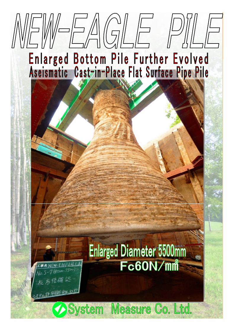
Enlarged Bottom Pile with Progressive Evolution inPile Head Bearing Force, Concrete Design Strength andInclination of Enlarged Bottom Part
Special Features
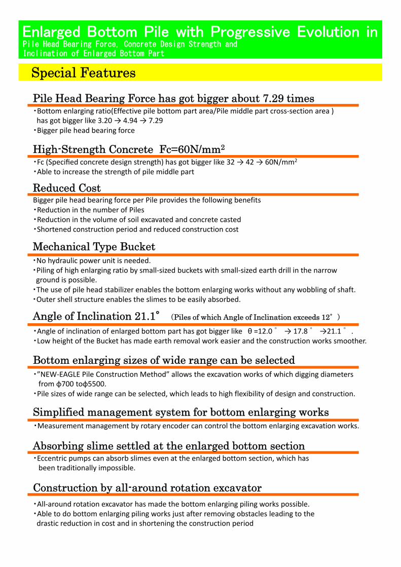
・Bottom enlarging ratio(Effective pile bottom part area/Pile middle part cross‐section area )has got bigger like 3.20 → 4.94 → 7.29
・Bigger pile head bearing force
Pile Head Bearing Force has got bigger about 7.29 times
High-Strength Concrete Fc=60N/mm2
・Fc (Specified concrete design strength) has got bigger like 32 → 42 → 60N/mm2
・Able to increase the strength of pile middle part
Bigger pile head bearing force per Pile provides the following benefits・Reduction in the number of PilesR d ti i th l f il t d d t t d
High Strength Concrete Fc 60N/mm
Reduced Cost
・Reduction in the volume of soil excavated and concrete casted・Shortened construction period and reduced construction cost
・No hydraulic power unit is needed.・Piling of high enlarging ratio by small‐sized buckets with small‐sized earth drill in the narrowground is possible.
Mechanical Type Bucket
g p・The use of pile head stabilizer enables the bottom enlarging works without any wobbling of shaft.・Outer shell structure enables the slimes to be easily absorbed.
・Angle of inclination of enlarged bottom part has got bigger like θ =12.0°→ 17.8°→21.1°.・Low height of the Bucket has made earth removal work easier and the construction works smoother.
Angle of Inclination 21.1°(Piles of which Angle of Inclination exceeds 12°)
・”NEW‐EAGLE Pile Construction Method” allows the excavation works of which digging diameters from φ700 toφ5500.
・Pile sizes of wide range can be selected, which leads to high flexibility of design and construction.
Bottom enlarging sizes of wide range can be selected
Simplified management system for bottom enlarging works・Measurement management by rotary encoder can control the bottom enlarging excavation works.
・Eccentric pumps can absorb slimes even at the enlarged bottom section, which has been traditionally impossible.
Simplified management system for bottom enlarging works
Absorbing slime settled at the enlarged bottom section
・All‐around rotation excavator has made the bottom enlarging piling works possible.・Able to do bottom enlarging piling works just after removing obstacles leading to the drastic reduction in cost and in shortening the construction period
Construction by all-around rotation excavator
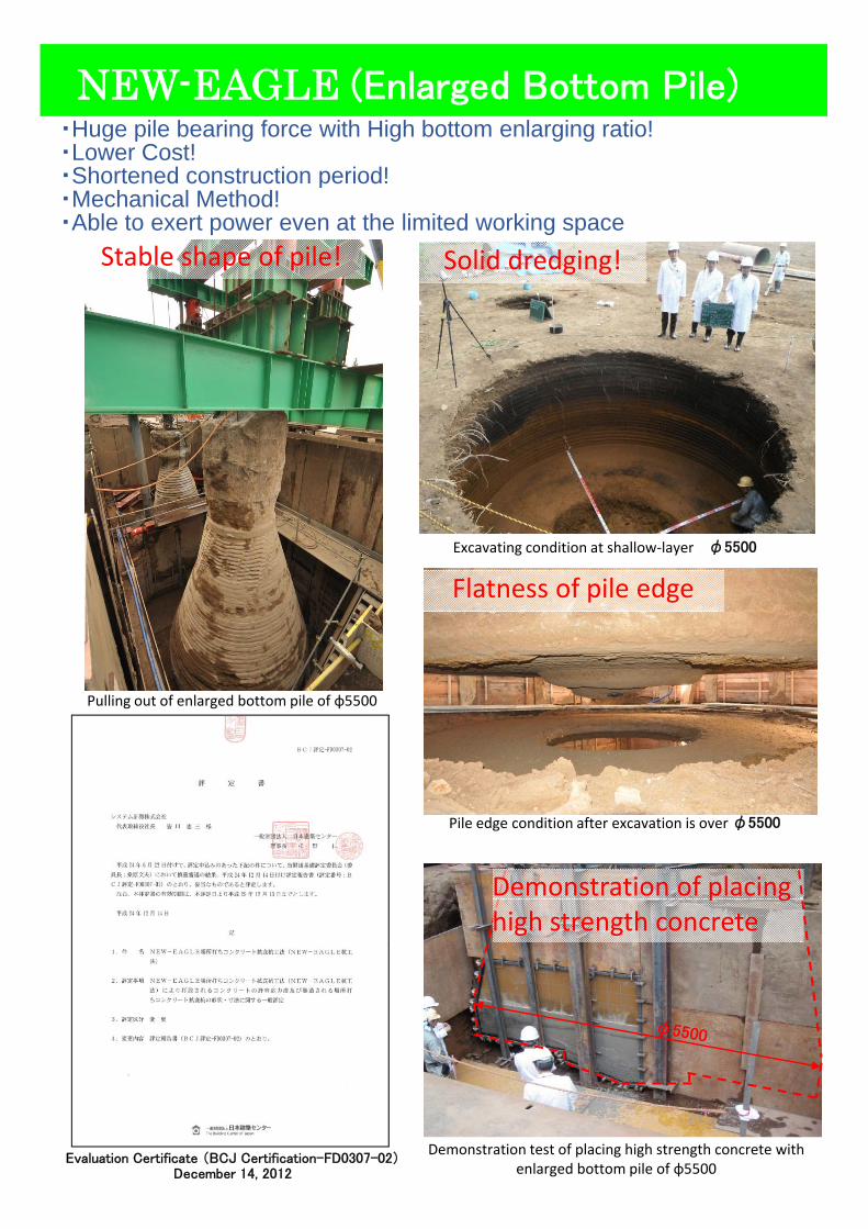
NEW-EAGLE (Enlarged Bottom Pile)・Huge pile bearing force with High bottom enlarging ratio!・Lower Cost!・Shortened construction period!
Stable shape of pile! Solid dredging!
p・Mechanical Method!・Able to exert power even at the limited working space
Excavating condition at shallow‐layer φ5500
Flatness of pile edge
Pulling out of enlarged bottom pile of φ5500
Demonstration of placing
Pile edge condition after excavation is over φ5500
p ghigh strength concrete
Evaluation Certificate (BCJ Certification-FD0307-02)December 14, 2012
Demonstration test of placing high strength concrete with enlarged bottom pile of φ5500
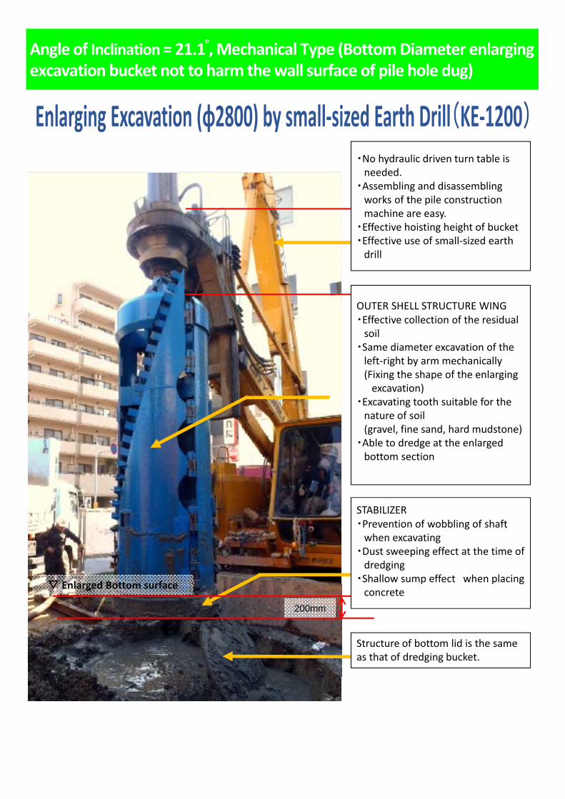
Angle of Inclination= 21.1゚, Mechanical Type (Bottom Diameter enlarging excavation bucket not to harm the wall surface of pile hole dug)
・No hydraulic driven turn table is needed.
・Assembling and disassembling works of the pile construction machine are easy
OUTER SHELL STRUCTURE WING
machine are easy. ・Effective hoisting height of bucket・Effective use of small‐sized earth drill
OUTER SHELL STRUCTURE WING ・Effective collection of the residual soil
・Same diameter excavation of the left‐right by arm mechanically(Fixing the shape of the enlarging excavation)
E ti t th it bl f th・Excavating tooth suitable for the nature of soil (gravel, fine sand, hard mudstone)
・Able to dredge at the enlarged bottom section
▽ Enlarged Bottom surface
STABILIZER・Prevention of wobbling of shaft when excavating
・Dust sweeping effect at the time of dredging
・Shallow sump effect when placing
200mm
▽ Enlarged Bottom surface
Structure of bottom lid is the same as that of dredging bucket.
concrete
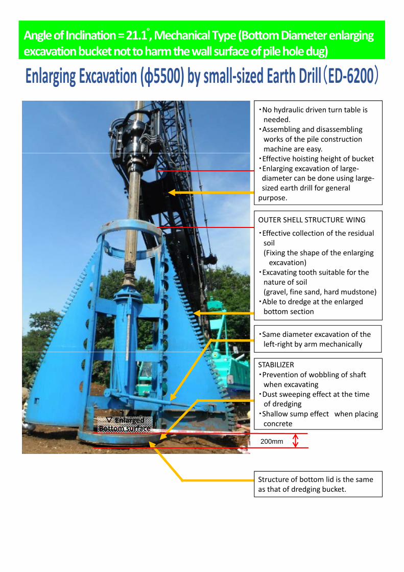
Angle of Inclination = 21.1 ,゚ Mechanical Type (Bottom Diameter enlarging excavation bucket not to harm the wall surface of pile hole dug)
・No hydraulic driven turn table is needed.
・Assembling and disassembling works of the pile construction machine are easy.
・Effective hoisting height of bucket・Enlarging excavation of large‐diameter can be done using large‐sized earth drill for general purpose.
OUTER SHELL STRUCTURE WINGOUTER SHELL STRUCTURE WING
・Effective collection of the residual soil (Fixing the shape of the enlarging excavation)
・Excavating tooth suitable for the nature of soil (gravel, fine sand, hard mudstone)
・Able to dredge at the enlarged bottom section
・Same diameter excavation of the left‐right by arm mechanically
▽ E l d
STABILIZER・Prevention of wobbling of shaft when excavating
・Dust sweeping effect at the time of dredging
・Shallow sump effect when placing
200mm
▽ Enlarged Bottom surface concrete
Structure of bottom lid is the same as that of dredging bucket.
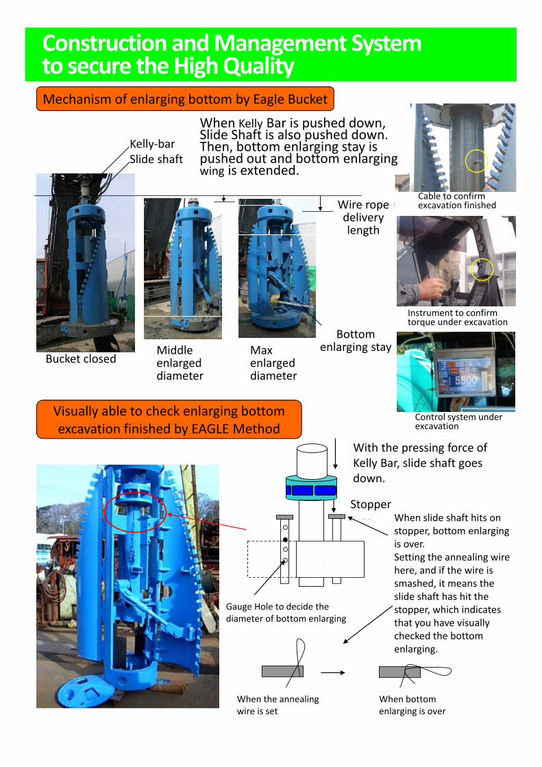
Construction and Management System to secure the High QualityMechanism of enlarging bottom by Eagle Bucket
ケリバーを押し下げると、スライド軸も下がる。
スライド軸に取り付けられている拡底ステイが
押し出され、拡底翼が広がる。
ワイヤー繰り出し長
ケリバー
スライド軸Kelly‐barSlide shaft
When Kelly Bar is pushed down, Slide Shaft is also pushed down. Then, bottom enlarging stay is pushed out and bottom enlarging wing is extended.
Wire ropeCable to confirm excavation finishedワイヤ 繰り出し長Wire rope
delivery length
excavation finished
バケット閉 拡底中 拡底最大径
拡底ステイBottom
enlarging stayBucket closed
Middle enlarged diameter
Max enlarged diameter
Instrument to confirm torque under excavation
ケリーバの押込み力でスライド軸が下がる
Visually able to check enlarging bottom excavation finished by EAGLE Method
Control system under excavation
With the pressing force of Kelly Bar, slide shaft goes
ストッパー
スライド軸がストッパーにぶつかれば拡底終了
番線を お
down.
StopperWhen slide shaft hits on stopper, bottom enlarging is over.Setting the annealing wire ここに番線をつけておいて番線がつぶれたらスライド軸がストッパーまできたことになるので目視で拡底したことがわかる
ピン穴ピン穴の位置で拡底径を決定
g ghere, and if the wire is smashed, it means the slide shaft has hit the stopper, which indicates that you have visually checked the bottom enlarging
Gauge Hole to decide the diameter of bottom enlarging
取付時 拡底完了時
enlarging.
When the annealing wire is set
When bottom enlarging is over
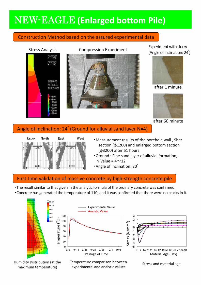
NEW-EAGLE (Enlarged bottom Pile)
Construction Method based on the assured experimental data
Stress Analysis Compression Experiment Experiment with slurry(Angle of inclination: 24 )゚
after 1 minute
Angle of inclination: 24゚ (Ground for alluvial sand layer N=4)
・Measurement results of the borehole wall , Shat South North East West
after 60 minute
section (φ1200) and enlarged bottom section(φ3200) after 51 hours
・Ground : Fine sand layer of alluvial formation, N Value = 4~12
・Angle of inclination: 20°3200
1200 1200
3200
First time validation of massive concrete by high‐strength concrete pile
‐‐‐‐‐‐‐‐ Experimental Value
・The result similar to that given in the analytic formula of the ordinary concrete was confirmed. ・Concrete has generated the temperature of 110, and it was confirmed that there were no cracks in it.
20
40
60
80
100
120
温度
(℃)
実験値
解析値
-3
-2
-1
0
1
2
3
応力
(N
/m
m2 )
mpe
rature (℃
)
ress (N
/mm
2 )
p‐‐‐‐‐‐‐‐ Analytic Value
Humidity Distribution (at the maximum temperature)
0
20
9/6 9/11 9/16 9/21 9/26 10/1 10/6
経過
-5
-4
0 7 14 21 28 35 42 49 56 63 70 77 84 91
応
材齢(日)
Stress and material ageTemperature comparison between experimental and analytic values
Material Age (Day)
Tem
Str
Passage of Time
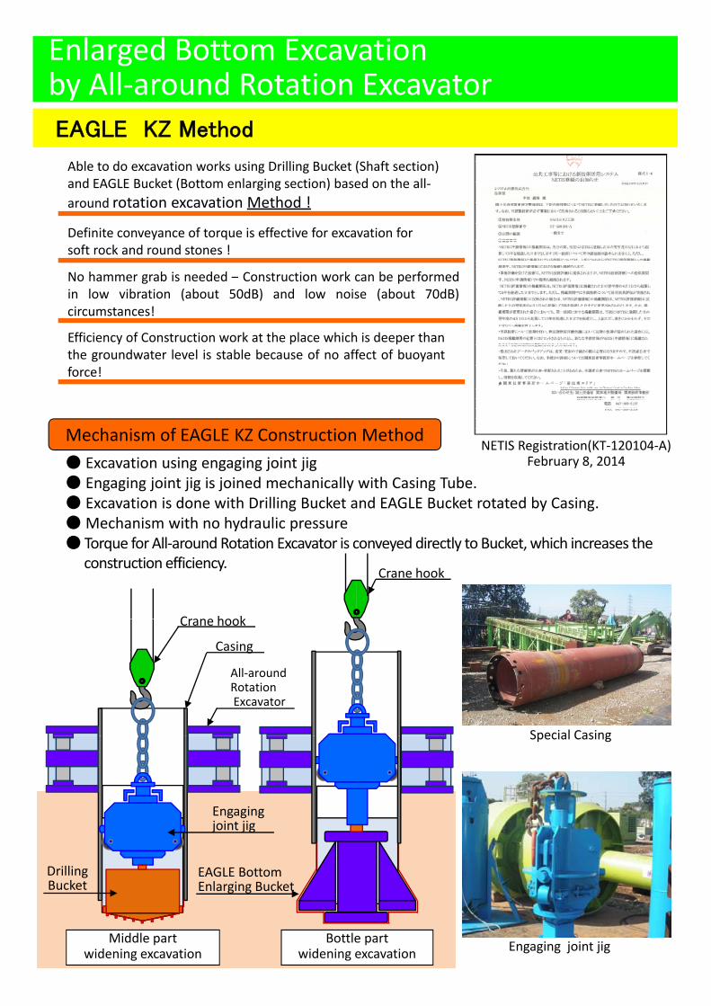
Enlarged Bottom Excavation by All‐around Rotation ExcavatorEAGLE KZ Method
Able to do excavation works using Drilling Bucket (Shaft section) and EAGLE Bucket (Bottom enlarging section) based on the all‐around rotation excavation Method !
Definite conveyance of torque is effective for excavation for soft rock and round stones !
No hammer grab is needed – Construction work can be performedin low vibration (about 50dB) and low noise (about 70dB)circumstances!
Efficiency of Construction work at the place which is deeper thanthe groundwater level is stable because of no affect of buoyantforce!
● Excavation using engaging joint jig● Engaging joint jig is joined mechanically with Casing Tube.● Excavation is done with Drilling Bucket and EAGLE Bucket rotated by Casing
NETIS Registration(KT‐120104‐A)February 8, 2014
Mechanism of EAGLE KZ Construction Method
Crane hook
● Excavation is done with Drilling Bucket and EAGLE Bucket rotated by Casing.● Mechanism with no hydraulic pressure ● Torque for All‐around Rotation Excavator is conveyed directly to Bucket, which increases the
construction efficiency.
Crane hookCrane hook
Casing
All‐around RotationExcavator
Special CasingSpecial Casing
Engaging joint jig
係合接合治具Engaging joint jig
Drilling Bucket
EAGLE BottomEnlarging Bucket
Middle partwidening excavation
Bottle partwidening excavation
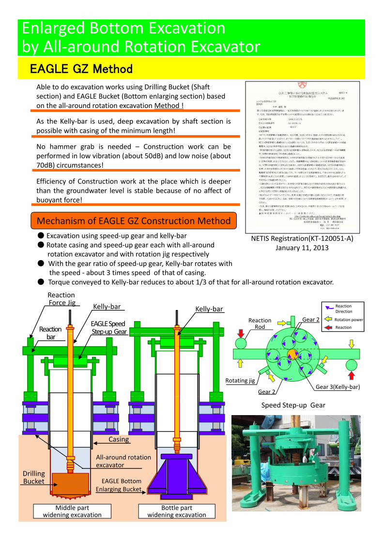
Enlarged Bottom Excavation by All‐around Rotation Excavator
EAGLE GZ Method
Able to do excavation works using Drilling Bucket (Shaft section) and EAGLE Bucket (Bottom enlarging section) based on the all‐around rotation excavation Method !
As the Kelly‐bar is used, deep excavation by shaft section ispossible with casing of the minimum length!
N h b i d d C t ti k bNo hammer grab is needed – Construction work can beperformed in low vibration (about 50dB) and low noise (about70dB) circumstances!
Efficiency of Construction work at the place which is deeperthan the groundwater level is stable because of no affect ofbuoyant force!
NETIS Registration(KT‐120051‐A)January 11, 2013
● Excavation using speed‐up gear and kelly‐bar● Rotate casing and speed‐up gear each with all‐around
rotation excavator and with rotation jig respectively● With the gear ratio of speed‐up gear, Kelly‐bar rotates with
th d b t 3 ti d f th t f i
Mechanism of EAGLE GZ Construction Method
the speed ‐ about 3 times speed of that of casing. ● Torque conveyed to Kelly‐bar reduces to about 1/3 of that for all‐around rotation excavator.
EAGLE SpeedStep‐up Gear
Kelly‐bar Kelly‐bar
ReactionForce Jig
ReactionReaction Rod
Gear 2
ReactionDirection
Rotation power
ReactionStepup Gear
bar
Gear 2Gear 3(Kelly‐bar)
Rotating jig
Speed Step‐up Gear
Casing
All‐around rotationAll around rotation excavator
Drilling Bucket EAGLE Bottom
Enlarging Bucket
Bottle partwidening excavation
Middle partwidening excavation
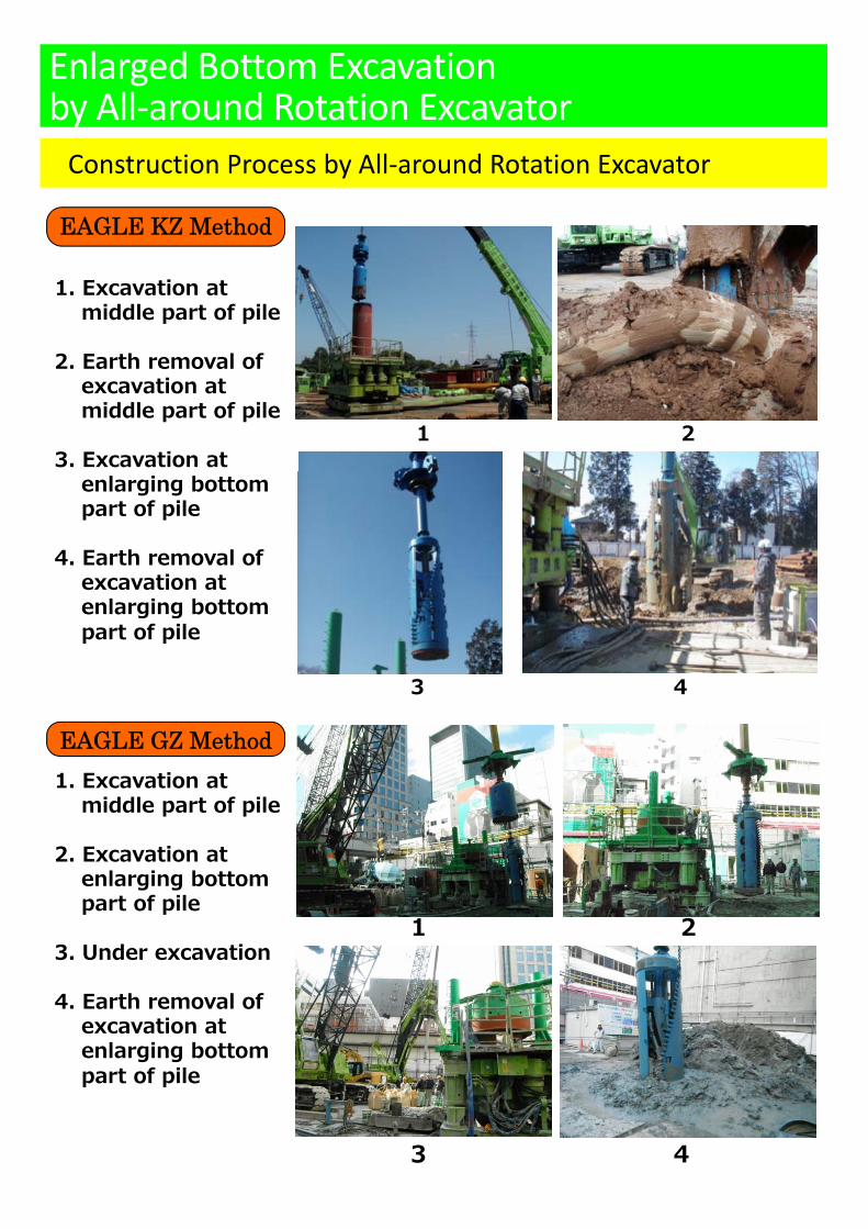
Construction Process by All‐around Rotation Excavator
Enlarged Bottom Excavation by All‐around Rotation Excavator
EAGLE KZ Method
1. Excavation at middle part of pile
2. Earth removal of excavation at middle part of pile
3. Excavation at 1 2
enlarging bottom part of pile
4. Earth removal of excavation at enlarging bottomenlarging bottom part of pile
3 4
EAGLE GZ Method1. Excavation at
middle part of pile
2. Excavation at enlarging bottom
t f il1 2
part of pile
3. Under excavation
4. Earth removal of excavation at
3 4
enlarging bottom part of pile
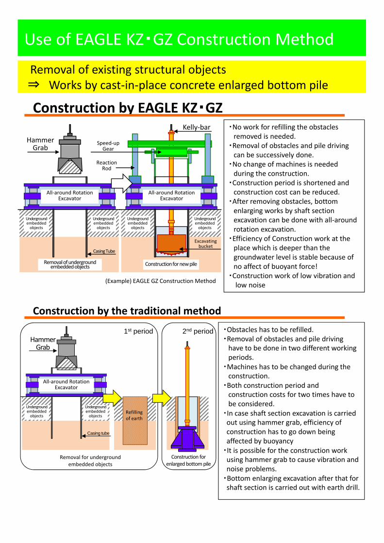
Use of EAGLE KZ・GZ Construction Method
Removal of existing structural objects ⇒ W k b t i l t l d b tt il⇒ Works by cast‐in‐place concrete enlarged bottom pile
Construction by EAGLE KZ・GZ ・No work for refilling the obstacles removed is needed.
・Removal of obstacles and pile driving
Kelly‐bar
Hammer G b
Speed‐up ・Removal of obstacles and pile driving can be successively done.
・No change of machines is needed during the construction.
・Construction period is shortened and construction cost can be reduced.
・After removing obstacles, bottom l i k b h f i
Grabp pGear
Reaction Rod
All‐around RotationExcavator
All‐around RotationExcavator
enlarging works by shaft section excavation can be done with all‐around rotation excavation.
・Efficiency of Construction work at the place which is deeper than the groundwater level is stable because of no affect of buoyant force!
Undergroundembedded objects
Undergroundembedded objects
Undergroundembedded objects
Undergroundembedded objects
Casing Tube
Excavating bucket
Removal of underground embedded objects Construction for new pile
・Construction work of low vibration andlow noise
Construction by the traditional method・Obstacles has to be refilled.1st period 2nd period
(Example) EAGLE GZ Construction Method
・Removal of obstacles and pile driving have to be done in two different working periods.
・Machines has to be changed during the construction.
・Both construction period and construction costs for two times have to
p pHammer Grab
All‐around RotationExcavator
be considered. ・In case shaft section excavation is carried out using hammer grab, efficiency of construction has to go down being affected by buoyancy
・It is possible for the construction work using hammer grab to cause vibration andRemoval for underground Construction for
Undergroundembedded objects
Undergroundembedded objects
Refilling of earth
Casing tube
using hammer grab to cause vibration and noise problems.
・Bottom enlarging excavation after that for shaft section is carried out with earth drill.
gembedded objects enlarged bottom pile
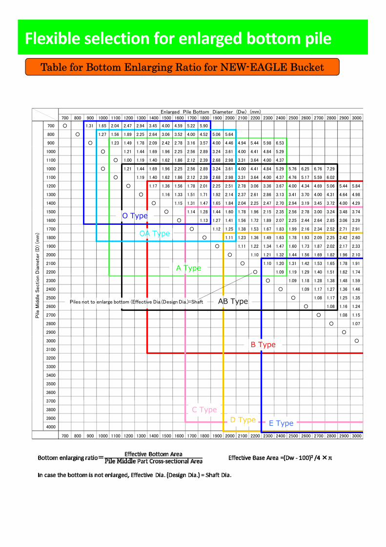
Flexible selection for enlarged bottom pileTable for Bottom Enlarging Ratio for NEW-EAGLE Bucket
700 800 900 1000 1100 1200 1300 1400 1500 1600 1700 1800 1900 2000 2100 2200 2300 2400 2500 2600 2700 2800 2900 3000
700 ○ 1.00 1.31 1.65 2.04 2.47 2.94 3.45 4.00 4.59 5.22 5.90 6.61 7.37 8.16 9.00 9.88 #### #### #### #### #### #### ####
800 ○ 1.27 1.56 1.89 2.25 2.64 3.06 3.52 4.00 4.52 5.06 5.64 6.25 6.89 7.56 8.27 9.00 9.77 #### #### #### ####
900 ○ 1.23 1.49 1.78 2.09 2.42 2.78 3.16 3.57 4.00 4.46 4.94 5.44 5.98 6.53 7.11 7.72 8.35 9.00 9.68 ####
Enlarged Pile Bottom Diameter (Dw) (mm)
1000 0.36 0.49 0.64 ○ 1.21 1.44 1.69 1.96 2.25 2.56 2.89 3.24 3.61 4.00 4.41 4.84 5.29 6.25 6.76 7.29 7.84 8.41
1100 0.30 0.40 0.53 0.67 ○ 1.00 1.19 1.40 1.62 1.86 2.12 2.39 2.68 2.98 3.31 3.64 4.00 4.37 6.02 6.48 6.95
1000 0.36 0.49 0.64 ○ 1.00 1.21 1.44 1.69 1.96 2.25 2.56 2.89 3.24 3.61 4.00 4.41 4.84 5.29 5.76 6.25 6.76 7.29 7.84 8.41
1100 0.30 0.40 0.53 0.67 ○ 1.19 1.40 1.62 1.86 2.12 2.39 2.68 2.98 3.31 3.64 4.00 4.37 4.76 5.17 5.59 6.02 6.48 6.95
1200 0.25 0.34 0.44 0.56 0.69 ○ 1.17 1.36 1.56 1.78 2.01 2.25 2.51 2.78 3.06 3.36 3.67 4.00 4.34 4.69 5.06 5.44 5.84
1300 0.21 0.29 0.38 0.48 0.59 0.72 ○ 1.16 1.33 1.51 1.71 1.92 2.14 2.37 2.61 2.86 3.13 3.41 3.70 4.00 4.31 4.64 4.98
1400 0.18 0.25 0.33 0.41 0.51 0.62 0.73 ○ 1.15 1.31 1.47 1.65 1.84 2.04 2.25 2.47 2.70 2.94 3.19 3.45 3.72 4.00 4.29
○1500 0.16 0.22 0.28 0.36 0.44 0.54 0.64 0.75 ○ 1.14 1.28 1.44 1.60 1.78 1.96 2.15 2.35 2.56 2.78 3.00 3.24 3.48 3.74
1600 0.14 0.19 0.25 0.32 0.39 0.47 0.56 0.66 0.77 ○ 1.13 1.27 1.41 1.56 1.72 1.89 2.07 2.25 2.44 2.64 2.85 3.06 3.29
1700 ○ 1.12 1.25 1.38 1.53 1.67 1.83 1.99 2.16 2.34 2.52 2.71 2.91
1800 0.11 0.15 0.20 0.25 0.31 0.37 0.44 0.52 0.60 0.69 0.79 ○ 1.11 1.23 1.36 1.49 1.63 1.78 1.93 2.09 2.25 2.42 2.60
1900 0.10 0.14 0.18 0.22 0.28 0.34 0.40 0.47 0.54 0.62 0.71 0.80 ○ 1.11 1.22 1.34 1.47 1.60 1.73 1.87 2.02 2.17 2.33
2000 0.09 0.12 0.16 0.20 0.25 0.30 0.36 0.42 0.49 0.56 0.64 0.72 0.81 ○ 1.10 1.21 1.32 1.44 1.56 1.69 1.82 1.96 2.10
2100 0.08 0.11 0.15 0.18 0.23 0.27 0.33 0.38 0.44 0.51 0.58 0.66 0.73 0.82 ○ 1.10 1.20 1.31 1.42 1.53 1.65 1.78 1.91
2200 0.07 0.10 0.13 0.17 0.40 0.46 0.53 0.60 0.67 0.75 0.83 ○ 1.09 1.19 1.29 1.40 1.51 1.62 1.74Dia
mete
r (D
) (m
m) OA Type
A Type
O Type
2200 0.07 0.10 0.13 0.17 0.40 0.46 0.53 0.60 0.67 0.75 0.83 ○ 1.09 1.19 1.29 1.40 1.51 1.62 1.74
2300 0.07 0.09 0.12 0.15 0.19 0.23 0.27 0.32 0.37 0.43 0.48 0.55 0.61 0.68 0.76 0.83 ○ 1.09 1.18 1.28 1.38 1.48 1.59
2400 0.06 0.09 0.11 0.14 0.17 0.21 0.25 0.29 0.34 0.39 0.44 0.50 0.56 0.63 0.69 0.77 0.84 ○ 1.09 1.17 1.27 1.36 1.46
2500 0.06 0.08 0.10 0.13 0.16 0.19 0.23 0.27 0.31 0.36 0.41 0.46 0.52 0.58 0.64 0.71 0.77 0.85 ○ 1.08 1.17 1.25 1.35
2600 0.05 0.07 0.09 0.12 0.15 0.38 0.43 0.48 0.53 0.59 0.65 0.72 0.78 0.85 ○ 1.08 1.16 1.24
2700 0.05 0.07 0.09 0.11 0.14 0.17 0.20 0.23 0.27 0.31 0.35 0.40 0.44 0.50 0.55 0.60 0.66 0.73 0.79 0.86 ○ 1.08 1.15
2800 0.05 0.06 0.08 0.10 0.13 0.15 0.18 0.22 0.25 0.29 0.33 0.37 0.41 0.46 0.51 0.56 0.62 0.67 0.73 0.80 0.86 ○ 1.07
2900 0.04 0.06 0.08 0.10 0.12 0.14 0.17 0.20 0.23 0.27 0.30 0.34 0.39 0.43 0.48 0.52 0.58 0.63 0.68 0.74 0.80 0.87 ○
Pile
Mid
dle S
ection D
AB TypePiles not to enlarge bottom (Effective Dia.(Design Dia.)=Shaft
3000 0.04 0.05 0.07 0.09 0.11 0.13 0.16 0.19 0.22 0.25 0.28 0.32 0.36 0.40 0.44 0.49 0.54 0.59 0.64 0.69 0.75 0.81 0.87 ○
3100 0.04 0.05 0.07 0.08 0.10 0.13 0.30 0.34 0.38 0.42 0.46 0.50 0.55 0.60 0.65 0.70 0.76 0.82 0.88
3200 0.04 0.05 0.06 0.08 0.10 0.12 0.14 0.17 0.19 0.22 0.25 0.28 0.32 0.35 0.39 0.43 0.47 0.52 0.56 0.61 0.66 0.71 0.77 0.82
3300 0.03 0.04 0.06 0.07 0.09 0.11 0.13 0.16 0.18 0.21 0.24 0.27 0.30 0.33 0.37 0.40 0.44 0.49 0.53 0.57 0.62 0.67 0.72 0.77
3400 0.03 0.04 0.06 0.07 0.09 0.10 0.12 0.15 0.17 0.19 0.22 0.25 0.28 0.31 0.35 0.38 0.42 0.46 0.50 0.54 0.58 0.63 0.68 0.73
3500 0.03 0.04 0.05 0.07 0.08 0.10 0.12 0.14 0.16 0.18 0.21 0.24 0.26 0.29 0.33 0.36 0.40 0.43 0.47 0.51 0.55 0.60 0.64 0.69
3600 0.03 0.04 0.05 0.06 0.08 0.09 0.11 0.13 0.15 0.17 0.20 0.22 0.25 0.28 0.31 0.34 0.37 0.41 0.44 0.48 0.52 0.56 0.60 0.65
3700 0 03 0 04 0 05 0 06 0 07 0 09 0 11 0 12 0 14 0 16 0 19 0 21 0 24 0 26 0 29 0 32 0 35 0 39 0 42 0 46 0 49 0 53 0 57 0 61
B Type
3700 0.03 0.04 0.05 0.06 0.07 0.09 0.11 0.12 0.14 0.16 0.19 0.21 0.24 0.26 0.29 0.32 0.35 0.39 0.42 0.46 0.49 0.53 0.57 0.61
3800 0.02 0.03 0.04 0.06 0.07 0.08 0.10 0.12 0.14 0.16 0.18 0.20 0.22 0.25 0.28 0.31 0.34 0.37 0.40 0.43 0.47 0.50 0.54 0.58
3900 0.02 0.03 0.04 0.05 0.07 0.08 0.09 0.11 0.13 0.24 0.26 0.29 0.32 0.35 0.38 0.41 0.44 0.48 0.52 0.55
4000 0.02 0.03 0.04 0.05 0.06 0.08 0.09 0.11 0.12 0.14 0.16 0.18 0.20 0.23 0.25 0.28 0.30 0.33 0.36 0.39 0.42 0.46 0.49 0.53
700 800 900 1000 1100 1200 1300 1400 1500 1600 1700 1800 1900 2000 2100 2200 2300 2400 2500 2600 2700 2800 2900 3000
C TypeD Type E Type
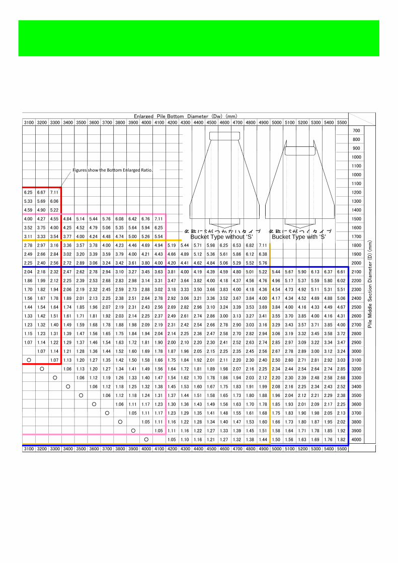
3100 3200 3300 3400 3500 3600 3700 3800 3900 4000 4100 4200 4300 4400 4500 4600 4700 4800 4900 5000 5100 5200 5300 5400 5500
#### #### #### #### #### #### #### #### #### #### #### #### #### #### #### #### #### #### #### #### #### #### #### #### #### 700
#### #### #### #### #### #### #### #### #### #### #### #### #### #### #### #### #### #### #### #### #### #### #### #### #### 800
#### #### #### #### #### #### #### #### #### #### #### #### #### #### #### #### #### #### #### #### #### #### #### #### #### 900
Enlarged Pile Bottom Diameter (Dw) (mm)
9.00 9.61 #### #### #### #### #### #### #### #### #### #### #### #### #### #### #### #### #### #### #### #### #### #### #### 1000
7.44 7.94 8.46 9.00 9.55 #### #### #### #### #### #### #### #### #### #### #### #### #### #### #### #### #### #### #### #### 1100
9.00 9.61 #### #### #### #### #### #### #### #### #### #### #### #### #### #### #### #### #### #### #### #### #### #### #### 1000
7.44 7.94 8.46 9.00 9.55 #### #### #### #### #### #### #### #### #### #### #### #### #### #### #### #### #### #### #### #### 1100
6.25 6.67 7.11 7.56 8.03 8.51 9.00 9.51 #### #### #### #### #### #### #### #### #### #### #### #### #### #### #### #### #### 1200
5.33 5.69 6.06 6.44 6.84 7.25 7.67 8.10 8.54 9.00 9.47 9.95 #### #### #### #### #### #### #### #### #### #### #### #### #### 1300
4.59 4.90 5.22 5.90 6.25 6.61 6.98 7.37 7.76 8.16 8.58 9.00 9.43 9.88 #### #### #### #### #### #### #### #### #### #### 1400
Figures show the Bottom Enlarged Ratio.
4.00 4.27 4.55 4.84 5.14 5.44 5.76 6.08 6.42 6.76 7.11 7.47 7.84 8.22 8.60 9.00 9.40 9.82 #### #### #### #### #### #### #### 1500
3.52 3.75 4.00 4.25 4.52 4.79 5.06 5.35 5.64 5.94 6.25 6.57 6.89 7.22 7.56 7.91 8.27 8.63 9.00 9.38 9.77 #### #### #### #### 1600
3.11 3.33 3.54 3.77 4.00 4.24 4.48 4.74 5.00 5.26 5.54 5.82 6.10 6.40 6.70 7.01 7.32 7.64 7.97 8.31 8.65 9.00 9.36 9.72 #### 1700
2.78 2.97 3.16 3.36 3.57 3.78 4.00 4.23 4.46 4.69 4.94 5.19 5.44 5.71 5.98 6.25 6.53 6.82 7.11 7.41 7.72 8.03 8.35 8.67 9.00 1800
2.49 2.66 2.84 3.02 3.20 3.39 3.59 3.79 4.00 4.21 4.43 4.66 4.89 5.12 5.36 5.61 5.86 6.12 6.38 6.65 6.93 7.20 7.49 7.78 8.08 1900
2.25 2.40 2.56 2.72 2.89 3.06 3.24 3.42 3.61 3.80 4.00 4.20 4.41 4.62 4.84 5.06 5.29 5.52 5.76 6.00 6.25 6.50 6.76 7.02 7.29 2000
2.04 2.18 2.32 2.47 2.62 2.78 2.94 3.10 3.27 3.45 3.63 3.81 4.00 4.19 4.39 4.59 4.80 5.01 5.22 5.44 5.67 5.90 6.13 6.37 6.61 2100
1 86 1 99 2 12 2 25 2 39 2 53 2 68 2 83 2 98 3 14 3 31 3 47 3 64 3 82 4 00 4 18 4 37 4 56 4 76 4 96 5 17 5 37 5 59 5 80 6 02 2200 Dia
mete
r (D
) (m
m)
名称にSがつくタイプ名称にSがつかないタイプBucket Type without ‘S’ Bucket Type with ‘S’
1.86 1.99 2.12 2.25 2.39 2.53 2.68 2.83 2.98 3.14 3.31 3.47 3.64 3.82 4.00 4.18 4.37 4.56 4.76 4.96 5.17 5.37 5.59 5.80 6.02 2200
1.70 1.82 1.94 2.06 2.19 2.32 2.45 2.59 2.73 2.88 3.02 3.18 3.33 3.50 3.66 3.83 4.00 4.18 4.36 4.54 4.73 4.92 5.11 5.31 5.51 2300
1.56 1.67 1.78 1.89 2.01 2.13 2.25 2.38 2.51 2.64 2.78 2.92 3.06 3.21 3.36 3.52 3.67 3.84 4.00 4.17 4.34 4.52 4.69 4.88 5.06 2400
1.44 1.54 1.64 1.74 1.85 1.96 2.07 2.19 2.31 2.43 2.56 2.69 2.82 2.96 3.10 3.24 3.39 3.53 3.69 3.84 4.00 4.16 4.33 4.49 4.67 2500
1.33 1.42 1.51 1.61 1.71 1.81 1.92 2.03 2.14 2.25 2.37 2.49 2.61 2.74 2.86 3.00 3.13 3.27 3.41 3.55 3.70 3.85 4.00 4.16 4.31 2600
1.23 1.32 1.40 1.49 1.59 1.68 1.78 1.88 1.98 2.09 2.19 2.31 2.42 2.54 2.66 2.78 2.90 3.03 3.16 3.29 3.43 3.57 3.71 3.85 4.00 2700
1.15 1.23 1.31 1.39 1.47 1.56 1.65 1.75 1.84 1.94 2.04 2.14 2.25 2.36 2.47 2.58 2.70 2.82 2.94 3.06 3.19 3.32 3.45 3.58 3.72 2800
1.07 1.14 1.22 1.29 1.37 1.46 1.54 1.63 1.72 1.81 1.90 2.00 2.10 2.20 2.30 2.41 2.52 2.63 2.74 2.85 2.97 3.09 3.22 3.34 3.47 2900
Pile
Mid
dle S
ection D
1.07 1.14 1.21 1.28 1.36 1.44 1.52 1.60 1.69 1.78 1.87 1.96 2.05 2.15 2.25 2.35 2.45 2.56 2.67 2.78 2.89 3.00 3.12 3.24 3000
○ 1.07 1.13 1.20 1.27 1.35 1.42 1.50 1.58 1.66 1.75 1.84 1.92 2.01 2.11 2.20 2.30 2.40 2.50 2.60 2.71 2.81 2.92 3.03 3100
0.88 ○ 1.06 1.13 1.20 1.27 1.34 1.41 1.49 1.56 1.64 1.72 1.81 1.89 1.98 2.07 2.16 2.25 2.34 2.44 2.54 2.64 2.74 2.85 3200
0.83 0.88 ○ 1.06 1.12 1.19 1.26 1.33 1.40 1.47 1.54 1.62 1.70 1.78 1.86 1.94 2.03 2.12 2.20 2.30 2.39 2.48 2.58 2.68 3300
0.78 0.83 0.89 ○ 1.06 1.12 1.18 1.25 1.32 1.38 1.45 1.53 1.60 1.67 1.75 1.83 1.91 1.99 2.08 2.16 2.25 2.34 2.43 2.52 3400
0.73 0.78 0.84 0.89 ○ 1.06 1.12 1.18 1.24 1.31 1.37 1.44 1.51 1.58 1.65 1.73 1.80 1.88 1.96 2.04 2.12 2.21 2.29 2.38 3500
0.69 0.74 0.79 0.84 0.89 ○ 1.06 1.11 1.17 1.23 1.30 1.36 1.43 1.49 1.56 1.63 1.70 1.78 1.85 1.93 2.01 2.09 2.17 2.25 3600
0 66 0 70 0 75 0 80 0 84 0 89 ○ 1 05 1 11 1 17 1 23 1 29 1 35 1 41 1 48 1 55 1 61 1 68 1 75 1 83 1 90 1 98 2 05 2 13 37000.66 0.70 0.75 0.80 0.84 0.89 ○ 1.05 1.11 1.17 1.23 1.29 1.35 1.41 1.48 1.55 1.61 1.68 1.75 1.83 1.90 1.98 2.05 2.13 3700
0.62 0.67 0.71 0.75 0.80 0.85 0.90 ○ 1.05 1.11 1.16 1.22 1.28 1.34 1.40 1.47 1.53 1.60 1.66 1.73 1.80 1.87 1.95 2.02 3800
0.59 0.63 0.67 0.72 0.76 0.81 0.85 0.90 ○ 1.05 1.11 1.16 1.22 1.27 1.33 1.39 1.45 1.51 1.58 1.64 1.71 1.78 1.85 1.92 3900
0.56 0.60 0.64 0.68 0.72 0.77 0.81 0.86 0.90 ○ 1.05 1.10 1.16 1.21 1.27 1.32 1.38 1.44 1.50 1.56 1.63 1.69 1.76 1.82 4000
3100 3200 3300 3400 3500 3600 3700 3800 3900 4000 4100 4200 4300 4400 4500 4600 4700 4800 4900 5000 5100 5200 5300 5400 5500
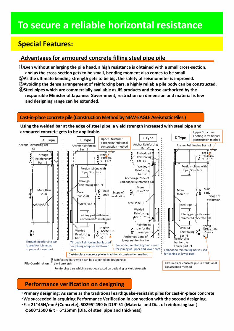
To secure a reliable horizontal resistance
Special Features:
Advantages for armoured concrete filling steel pipe pile ①Even without enlarging the pile head, a high resistance is obtained with a small cross‐section,
and as the cross‐section gets to be small, bending moment also comes to be small.②As the ultimate bending strength gets to be big, the safety of seismometer is improved.③Avoiding the dense arrangement of reinforcing bars, a highly reliable pile body can be constructed.④St l i hi h i ll il bl JIS d t d th th i d b th④Steel pipes which are commercially available as JIS products and those authorized by the
responsible Minister of Japanese Government, restriction on dimension and material is fewand designing range can be extended.
Cast‐in‐place concretepile (ConstructionMethodbyNEW‐EAGLEAseismatic Piles )Using the welded bar at the edge of steel pipe, a yield strength increased with steel pipe andUsing the welded bar at the edge of steel pipe, a yield strength increased with steel pipe and armoured concrete gets to be applicable.
A Type B Type C Type D Type
Anchor Reinforcing Bar r2
Anchor Reinforcing Bar r2
Anchor Reinforcing Bar r2
Anchor Reinforcing Bar r2
ThroughReinforcing Bar r1
Upper Structure・Footing in traditionalconstruction method
Embedded Reinforcing bar r1
h
Upper Structure・Footing in traditionalconstruction method
More than 2.5D
Portion joining with Upper Structure
ThroughReinforcing Bar r1
More than 2.5D
Steel Pipe S
Scope of evaluation
Main body
Welded Reinforcing bar r2
Anchorage Zone of Embedded Reinforcing bar
More than 2.5D
Steel Pipe S
Portion joining with Upper Structure
More than 2.5D
l
Scope of evaluation
Main body
Steel Pipe S
Through Reinforcing bar Through Reinforcing bar is used
Steel Pipe S
Joining part with lower reinforced concrete pile
Steel Pipe S
Anchorage Zone of lower reinforcing bar
Welded Reinforcing bar r3
Welded Reinforcing bar r3
Reinforcing bar for the Lower part r1
Welded Reinforcing bar r3
Reinforcing bar for the
Joining part with lower reinforced concrete pile
Steel Pipe S
Pile Combination n:設計上耐力として評価する鉄筋
:設計上耐力として評価しない鉄筋
Through Reinforcing bar is used for joining at upper and lower part
Through Reinforcing bar is used for joining at upper and lower part
Reinforcing bars which can be evaluated on designing as yield strength
Reinforcing bars which are not evaluated on designing as yield strength
Cast‐in‐place concrete pile in traditional construction method
Embedded reinforcing bar is used for joining at upper and lower part Embedded reinforcing bar is used
for joining at lower part
bar for the Lower part r1
Cast‐in‐place concrete pile in traditional construction method
Performance verification on designing・Primary designing: As same as the traditional earthquake‐resistant piles for cast‐in‐place concrete ・We succeeded in acquiring Performance Verification in connection with the second designing. ・Fc = 21~45N/mm2 (Concrete), SD295~490 & D19~51 (Material and Dia. of reinforcing bar )φ600~2500 & t = 6~25mm (Dia. of steel pipe and thickness)
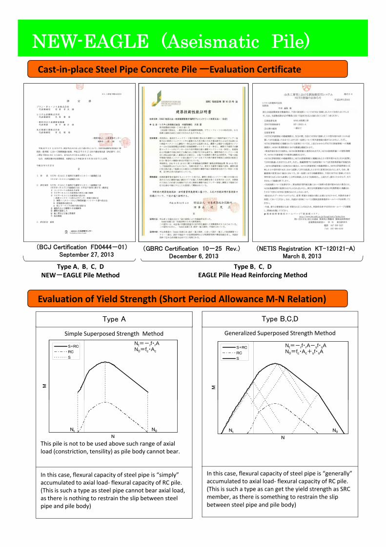
NEW-EAGLE (Aseismatic Pile)Cast‐in‐place Steel Pipe Concrete Pile ーEvaluation Certificate
GBRC 性能証明 第10-25号 改平成23年12月6日登録
BCJ 評定-FD0444-01平成25年9月27日登録
NETIS登録 (KT-120121-A)平成25年3月8日登録
Type A,B,C,DNEW EAGLE Pil M th d
Type B,C,DEAGLE Pil H d R i f i M th d
(BCJ Certification FD0444-01)September 27, 2013
(GBRC Certification 10-25 Rev.)December 6, 2013
(NETIS Registration KT-120121-A)March 8, 2013
Evaluation of Yield Strength (Short Period Allowance M‐N Relation)
Simple Superposed Strength Method
Type A
Generalized Superposed Strength Method
Type B,C,D
NEW-EAGLE Pile Method EAGLE Pile Head Reinforcing Method
p p p g
M
S+RC
RC
S
Nt=-rf・rAN0=fc・Ac
M
S+RC
RC
S
Nt=-rf・rA-sf・sAN0=fc・Ac+sf・sA
This pile is not to be used above such range of axial load (constriction, tensility) as pile body cannot bear.
N
Nt N0
N
Nt N0
In this case, flexural capacity of steel pipe is “simply” accumulated to axial load‐ flexural capacity of RC pile.(This is such a type as steel pipe cannot bear axial load, as there is nothing to restrain the slip between steel pipe and pile body)
In this case, flexural capacity of steel pipe is “generally” accumulated to axial load‐ flexural capacity of RC pile.(This is such a type as can get the yield strength as SRC member, as there is something to restrain the slip between steel pipe and pile body)
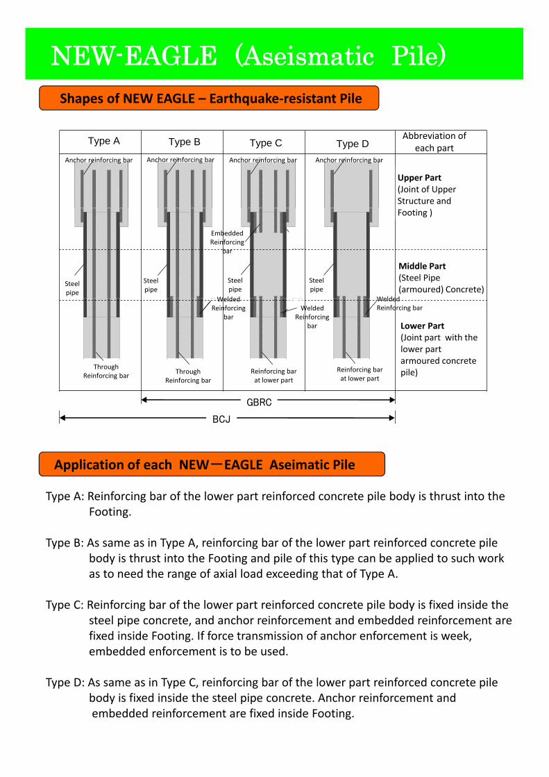
NEW-EAGLE (Aseismatic Pile)Shapes of NEW EAGLE – Earthquake‐resistant Pile
アンカー鉄筋 アンカー鉄筋 アンカー鉄筋 アンカー鉄筋
A タイプ B タイプ C タイプ D タイプ 各部の略名称
上部
(上部構造体・フーチング
との接合部)
Type A Type B Type C
Upper Part(Joint of Upper Structure and
Type DAbbreviation of
each partAnchor reinforcing bar Anchor reinforcing bar Anchor reinforcing barAnchor reinforcing bar
鋼管
溶接 鉄筋
鋼管溶接 鉄筋
鋼管鋼管 溶接 鉄筋
溶接 鉄筋
埋込み 鉄筋
中部
(鋼管(鉄筋)コンクリート部)
Footing )
Middle Part(Steel Pipe (armoured) Concrete)
Steelpipe
Steelpipe
Steelpipe
Steelpipe
EmbeddedReinforcing
bar
Welded Welded
下部鉄筋 下部鉄筋 通し鉄筋
鉄筋
通し鉄筋
鉄筋 鉄筋
下部
(下部鉄筋コンクリート杭体と
の継手部) Lower Part(Joint part with the lower part armoured concrete pile)
WeldedReinforcing
barWelded
Reinforcingbar
WeldedReinforcing bar
Reinforcing barat lower part
Reinforcing barat lower part
Through Reinforcing bar
Through Reinforcing bar
GBRC
BCJ
Application of each NEW-EAGLE Aseimatic Pile
Type A: Reinforcing bar of the lower part reinforced concrete pile body is thrust into the Footing.
Type B: As same as in Type A, reinforcing bar of the lower part reinforced concrete pile body is thrust into the Footing and pile of this type can be applied to such work as to need the range of axial load exceeding that of Type A.
Type C: Reinforcing bar of the lower part reinforced concrete pile body is fixed inside the steel pipe concrete, and anchor reinforcement and embedded reinforcement are fixed inside Footing. If force transmission of anchor enforcement is week, embedded enforcement is to be used.
Type D: As same as in Type C, reinforcing bar of the lower part reinforced concrete pile body is fixed inside the steel pipe concrete. Anchor reinforcement and embedded reinforcement are fixed inside Footing.
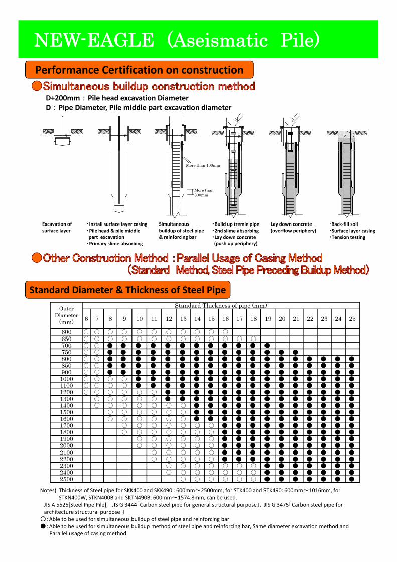
NEW-EAGLE (Aseismatic Pile)Performance Certification on construction
D+200mm : Pile head excavation DiameterD : Pipe Diameter, Pile middle part excavation diameter
More than300mm
More than 100mm
・Install surface layer casing・Pile head & pile middle part excavation
・Primary slime absorbing
Excavation of surface layer
Simultaneous buildup of steel pipe & reinforcing bar
・Build up tremie pipe・2nd slime absorbing・Lay down concrete(push up periphery)
Lay down concrete (overflow periphery)
・Back‐fill soil・Surface layer casing・Tension testing
Outer Diameter
(mm)
Standard Thickness of pipe (mm)
6 7 8 9 10 11 12 13 14 15 16 17 18 19 20 21 22 23 24 25
600 ○ ○ ○ ○ ○ ○ ○ ○ ○ ○ ○650 ○ ○ ○ ○ ○ ○ ○ ○ ○ ○ ○ ○ ○700 ○ ○ ● ● ● ● ● ● ● ● ● ● ● ●
Standard Diameter & Thickness of Steel Pipe
700 ○ ○ ● ● ● ● ● ● ● ● ● ● ● ●750 ○ ○ ● ● ● ● ● ● ● ● ● ● ● ● ● ●800 ○ ○ ● ● ● ● ● ● ● ● ● ● ● ● ● ● ● ● ● ●850 ○ ○ ● ● ● ● ● ● ● ● ● ● ● ● ● ● ● ● ● ●900 ○ ○ ● ● ● ● ● ● ● ● ● ● ● ● ● ● ● ● ● ●
1000 ○ ○ ○ ○ ● ● ● ● ● ● ● ● ● ● ● ● ● ● ● ●1100 ○ ○ ○ ○ ● ● ● ● ● ● ● ● ● ● ● ● ● ● ● ●1200 ○ ○ ○ ○ ○ ○ ● ● ● ● ● ● ● ● ● ● ● ● ● ●1300 ○ ○ ○ ○ ○ ● ● ● ● ● ● ● ● ● ● ● ● ● ●1400 ○ ○ ○ ○ ○ ○ ○ ● ● ● ● ● ● ● ● ● ● ● ●1500 ○ ○ ○ ○ ○ ○ ● ● ● ● ● ● ● ● ● ● ● ●1500 ○ ○ ○ ○ ○ ○ ● ● ● ● ● ● ● ● ● ● ● ●1600 ○ ○ ○ ○ ○ ○ ● ● ● ● ● ● ● ● ● ● ● ●1700 ○ ○ ○ ○ ○ ○ ○ ● ● ● ● ● ● ● ● ● ●1800 ○ ○ ○ ○ ○ ○ ○ ● ● ● ● ● ● ● ● ● ●1900 ○ ○ ○ ○ ○ ○ ● ● ● ● ● ● ● ● ● ●2000 ○ ○ ○ ○ ○ ○ ● ● ● ● ● ● ● ● ● ●2100 ○ ○ ○ ○ ○ ● ● ● ● ● ● ● ● ● ●2200 ○ ○ ○ ○ ○ ● ● ● ● ● ● ● ● ● ●2300 ○ ○ ○ ○ ○ ○ ○ ● ● ● ● ● ● ●2400 ○ ○ ○ ○ ○ ○ ○ ● ● ● ● ● ● ●2500 ○ ○ ○ ○ ○ ○ ● ● ● ● ● ● ●
Notes) Thickness of Steel pipe for SKK400 and SKK490 : 600mm~2500mm, for STK400 and STK490: 600mm~1016mm, for STKN400W, STKN400B and SKTN490B: 600mm~1574.8mm, can be used.
JIS A 5525[Steel Pipe Pile], JIS G 3444「Carbon steel pipe for general structural purpose」,JIS G 3475「Carbon steel pipe for architecture structural purpose 」
○:Able to be used for simultaneous buildup of steel pipe and reinforcing bar●:Able to be used for simultaneous buildup method of steel pipe and reinforcing bar, Same diameter excavation method and
Parallel usage of casing method
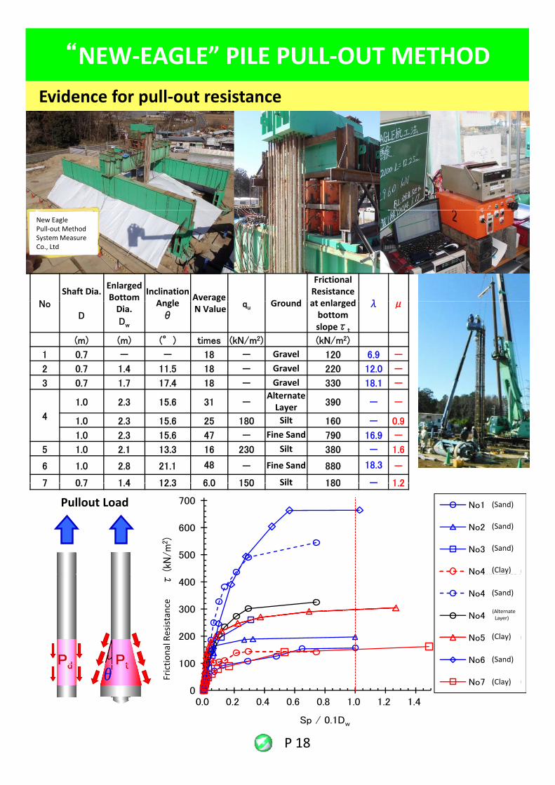
“NEW‐EAGLE” PILE PULL‐OUT METHODEvidence for pull‐out resistance
N
Shaft Dia. Enlarged Bottom Inclination A l Average G d
Frictional Resistance t l d λ
New EaglePull‐out MethodSystem Measure Co., Ltd
NoD
Dia.Dw
Angleθ
gN Value qu Ground at enlarged
bottomslopeτt
λ μ
(m) (m) (°) times (kN/m2) (kN/m2)
1 0.7 - - 18 - Gravel 120 6.9 -
2 0.7 1.4 11.5 18 - Gravel 220 12.0 -
3 0.7 1.7 17.4 18 - Gravel 330 18.1 -l
4
1.0 2.3 15.6 31 -Alternate Layer 390 - -
1.0 2.3 15.6 25 180 Silt 160 - 0.9
1.0 2.3 15.6 47 - Fine Sand 790 16.9 -
5 1.0 2.1 13.3 16 230 Silt 380 - 1.6
6 1.0 2.8 21.1 48 - Fine Sand 880 18.3 -
7 0 7 1 4 12 3 6 0 150 Silt 180 - 1 2
引抜き荷重
7 0.7 1.4 12.3 6.0 150 Silt 180 - 1.2
500
600
700
(kN
/m2 )
No1(砂質)
No2(砂質)
No3(砂質)
No4(粘土質)
Pullout Load (Sand)
(Sand)
(Sand)
(Clay)
Pd Pt 100
200
300
400
摩擦
抵抗
力度
τ
No4(粘土質)
No4(砂質)
No4(互層)
No5(粘土質)
No6(砂質)tional Resistance
(Sand)
(Clay)
(Sand)
(Alternate Layer)
P 18
θd t
0
100
0.0 0.2 0.4 0.6 0.8 1.0 1.2 1.4
Sp / 0.1Dw
No7(粘土質)
Frict
(Clay)
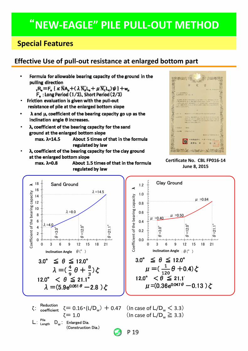
“NEW‐EAGLE” PILE PULL‐OUT METHODSpecial Features
Effective Use of pull‐out resistance at enlarged bottom part
Certificate No. CBL FP016‐14June 8, 2015
8
10
12
14
16
18
力係
数λ
支持力係数 λ
λ=8.0
λ=14.5
0.6
0.8
1.0
1.2
力係
数μ
支持力係数 μ
μ =0.84
μ =0 50
Sand Ground Clay Ground
earin
g capacity λ
aring capacity λ
0
2
4
6
8
0 3 6 9 12 15 18 21
支持
傾斜角θ(°)
λ=4.0
θ=3.0
°
θ=12.0
°
θ=21.1
°
0.0
0.2
0.4
0 3 6 9 12 15 18 21
支持
力
傾斜角θ(°)
μ =0.40μ 0.50
θ=3.0
°
θ=12.0
°
θ=21.1
°
Coefficient of the
b
Inclination Angle Coefficient of the
bea
Inclination Angle
P 19
ここに、ζ:低減係数 ζ= 0.16・(L/Dw) + 0.47 (In case of L/Dw < 3.3)
ζ= 1.0 (In case of L/Dw ≧ 3.3)L:杭長、Dw:拡底径(施工径)
Reduction coefficient
PileLength Enlarged Dia.
(Construction Dia.)
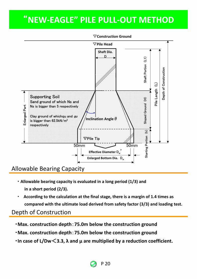
“NEW‐EAGLE” PILE PULL‐OUT METHOD
▽Construction Ground
Port
ion (L
1)
Shaft Dia.D
▽Pile Head
ction
und (H
)Shaf
t
Pile
Lengt
h(L
)
Depth
of
Const
ru
Supporting SoilSand ground of which Ns and Ns is bigger than 5 respectivelyrt
Inclination Angleθ
Slo
ped G
rou
▽Pile Tip
拡底
部
Ns is bigger than 5 respectively
Clay ground of whichqu and quis bigger than 62.5kN/m2
respectively
ion (h
)
Enla
rged
Pa
Allowable Bearing Capacity
Enlarged Bottom Dia. Dw
▽Pile Tip
Sta
rtin
g P
ort
i
Effective Diameter Dw’
50mm 50mm
・ Allowable bearing capacity is evaluated in a long period (1/3) and
in a short period (2/3).
・ According to the calculation at the final stage, there is a margin of 1.4 times as
compared with the ultimate load derived from safety factor (3/3) and loading test
g p y
compared with the ultimate load derived from safety factor (3/3) and loading test.
・Max. construction depth:75.0m below the construction ground
・Max. construction depth:75.0m below the construction ground
Depth of Construction
P 20
・In case of L/Dw<3.3, λ and μ are multiplied by a reduction coefficient.
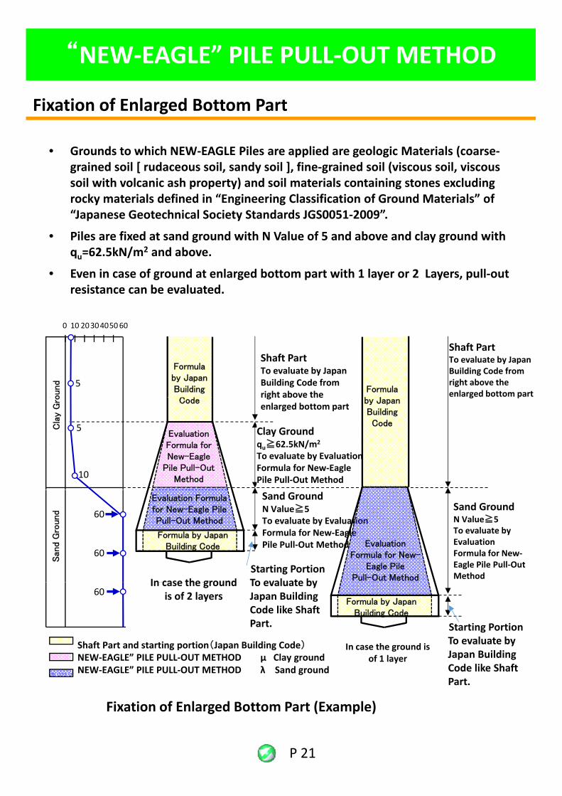
Fixation of Enlarged Bottom Part
“NEW‐EAGLE” PILE PULL‐OUT METHOD
• Grounds to which NEW‐EAGLE Piles are applied are geologic Materials (coarse‐grained soil [ rudaceous soil, sandy soil ], fine‐grained soil (viscous soil, viscous soil with volcanic ash property) and soil materials containing stones excluding rocky materials defined in “Engineering Classification of Ground Materials” of “Japanese Geotechnical Society Standards JGS0051 2009”“Japanese Geotechnical Society Standards JGS0051‐2009”.
• Piles are fixed at sand ground with N Value of 5 and above and clay ground with qu=62.5kN/m2 and above.
• Even in case of ground at enlarged bottom part with 1 layer or 2 Layers, pull‐out resistance can be evaluated.
粘
100 2030405060
5
Formula by Japan Building C d
Shaft PartTo evaluate by Japan Building Code from right above the
軸部
拡底部直上から告示式で評価
ound
Formula b J
Shaft PartTo evaluate by Japan Building Code from right above the enlarged bottom part粘
土質地盤
10
5
Coderight above theenlarged bottom part
Clay Groundqu≧62.5kN/m2
To evaluate by Evaluation Formula for New‐Eagle Pile Pull‐Out Method
Evaluation Formula for New-Eagle
Pile Pull-Out Method
Cla
y G
ro by Japan Building Code
g p
砂質地盤
60
60
2層地盤の場合
Sand GroundN Value≧5To evaluate by Evaluation Formula for New‐Eagle Pile Pull‐Out Method
Starting PortionTo evaluate byIn case the ground
Sand GroundN Value≧5To evaluate by Evaluation Formula for New‐Eagle Pile Pull‐Out Method
Formula by Japan Building Code
San
d G
round
Evaluation Formula for New-Eagle Pile Pull-Out Method
Evaluation Formula for New-
Eagle Pile Pull-Out Method
Shaft Part and starting portion(Japan Building Code)NEW‐EAGLE” PILE PULL‐OUT METHOD μ Clay groundNEW‐EAGLE” PILE PULL‐OUT METHOD λ Sand ground
2層地盤の場合 To evaluate by Japan Building Code like Shaft Part.
In case the ground is of 2 layers
立上り部軸部同様に告示式で評価
In case the ground is of 1 layer
60Formula by Japan
Building Code
Starting PortionTo evaluate by Japan Building Code like Shaft
P 21
g
Fixation of Enlarged Bottom Part (Example)
Part.
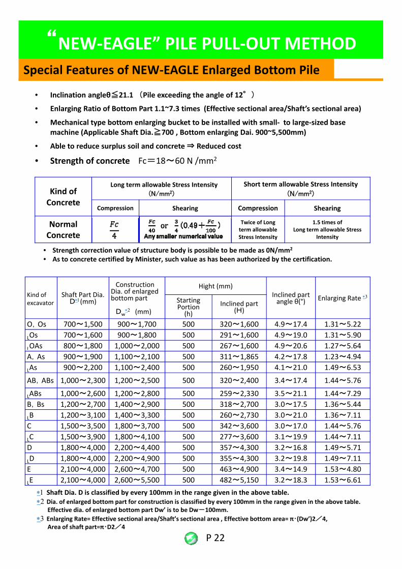
Special Features of NEW‐EAGLE Enlarged Bottom Pile
“NEW‐EAGLE” PILE PULL‐OUT METHOD
• Inclination angleθ≦21.1 (Pile exceeding the angle of 12°)
• Enlarging Ratio of Bottom Part 1.1~7.3 times (Effective sectional area/Shaft’s sectional area)
• Mechanical type bottom enlarging bucket to be installed with small‐ to large‐sized base machine (Applicable Shaft Dia.≧700 , Bottom enlarging Dai. 900~5,500mm)
• Able to reduce surplus soil and concrete ⇒ Reduced cost
Kind of Concrete
Long term allowable Stress Intensity (N/mm2)
Short term allowable Stress Intensity (N/mm2)
Compression Shearing Compression Shearing
• Strength of concrete Fc=18~60 N /mm2
Normal Concrete
Twice of Long term allowable Stress Intensity
1.5 times of Long term allowable Stress
Intensity
• Strength correction value of structure body is possible to be made as 0N/mm2
• As to concrete certified by Minister, such value as has been authorized by the certification.
Construction Hi ht ( )Kind of excavator
Shaft Part Dia.D∗1(mm)
ConstructionDia. of enlarged bottom part
Dw∗2 (mm)
Hight (mm)Inclined part angle θ(°) Enlarging Rate ∗3Starting
Portion(h)
Inclined part (H)
O,Os 700~1,500 900~1,700 500 320~1,600 4.9~17.4 1.31~5.22
LOs 700~1,600 900~1,800 500 291~1,600 4.9~19.0 1.31~5.90
LOAs 800~1,800 1,000~2,000 500 267~1,600 4.9~20.6 1.27~5.64A,As 900~1,900 1,100~2,100 500 311~1,865 4.2~17.8 1.23~4.94
LAs 900~2,200 1,100~2,400 500 260~1,950 4.1~21.0 1.49~6.53
AB,ABs 1,000~2,300 1,200~2,500 500 320~2,400 3.4~17.4 1.44~5.76
LABs 1,000~2,600 1,200~2,800 500 259~2,330 3.5~21.1 1.44~7.29B,Bs 1,200~2,700 1,400~2,900 500 318~2,700 3.0~17.5 1.36~5.44B 1 200~3 100 1 400~3 300 500 260~2 730 3 0~21 0 1 36~7 11LB 1,200 3,100 1,400 3,300 500 260 2,730 3.0 21.0 1.36 7.11C 1,500~3,500 1,800~3,700 500 342~3,600 3.0~17.0 1.44~5.76
LC 1,500~3,900 1,800~4,100 500 277~3,600 3.1~19.9 1.44~7.11D 1,800~4,000 2,200~4,400 500 357~4,300 3.2~16.8 1.49~5.71
LD 1,800~4,000 2,200~4,900 500 355~4,300 3.2~19.8 1.49~7.11E 2,100~4,000 2,600~4,700 500 463~4,900 3.4~14.9 1.53~4.80
LE 2,100~4,000 2,600~5,500 500 482~5,150 3.2~18.3 1.53~6.61
P 22
LE 2,100 4,000 2,600 5,500 500 482 5,150 3.2 18.3 1.53 6.61∗1 Shaft Dia. D is classified by every 100mm in the range given in the above table.∗2 Dia. of enlarged bottom part for construction is classified by every 100mm in the range given in the above table.
Effective dia. of enlarged bottom part Dw’ is to be Dw-100mm.∗3 Enlarging Rate= Effective sectional area/Shaft’s sectional area , Effective bottom area= π・(Dw’)2/4,
Area of shaft part=π・D2/4
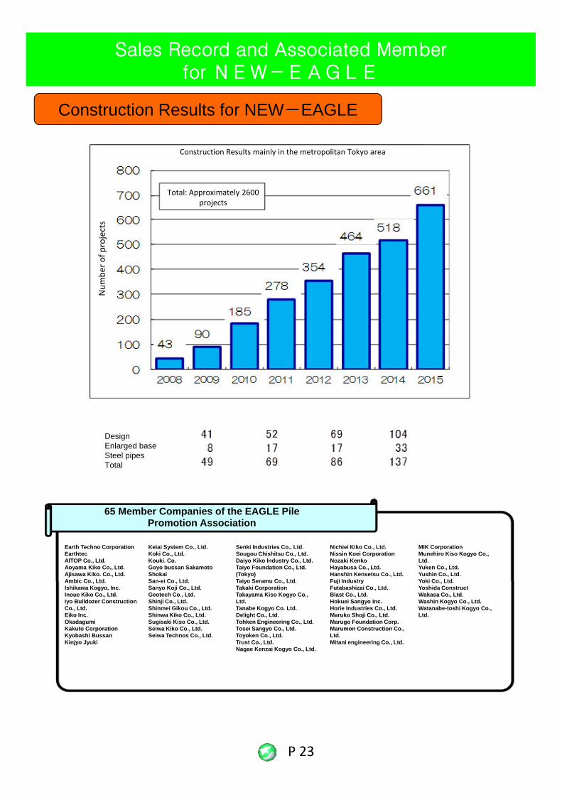
Sales Record and Associated Member for NEW-EAGLE
Construction Results for NEW-EAGLE
Total: Approximately 2600 projects
Construction Results mainly in the metropolitan Tokyo area
Num
ber o
f projects
DesignEnlarged baseSteel pipesTotal
65 Member Companies of the EAGLE Pile Promotion Association
Earth Techno CorporationEarthtecAITOP Co., Ltd.Aoyama Kiko Co., Ltd.Ajisawa Kiko. Co., Ltd.Ambic Co Ltd
Keiai System Co., Ltd.Koki Co., Ltd.Kouki. Co.Goyo bussan Sakamoto ShokaiSan-ei Co Ltd
Senki Industries Co., Ltd.Sougou Chishitsu Co., Ltd.Daiyo Kiko Industry Co., Ltd.Taiyo Foundation Co., Ltd. (Tokyo)Taiyo Seramu Co Ltd
Nichiei Kiko Co., Ltd.Nissin Koei CorporationNozaki KenkoHayabusa Co., Ltd.Hanshin Kensetsu Co., Ltd.Fuji Industry
MIK CorporationMunehiro Kiso Kogyo Co., Ltd.Yuken Co., Ltd.Yushin Co., Ltd.Yoki Co LtdAmbic Co., Ltd.
Ishikawa Kogyo, Inc.Inoue Kiko Co., Ltd.Iyo Bulldozer Construction Co., Ltd.Eiko Inc.OkadagumiKakuto CorporationKyobashi BussanKinjyo Jyuki
San-ei Co., Ltd.Sanyo Koji Co., Ltd.Geotech Co., Ltd.Shinji Co., Ltd.Shinmei Gikou Co., Ltd.Shinwa Kiko Co., Ltd.Sugisaki Kiso Co., Ltd.Seiwa Kiko Co., Ltd.Seiwa Technos Co., Ltd.
Taiyo Seramu Co., Ltd.Takaki CorporationTakayama Kiso Kogyo Co., Ltd.Tanabe Kogyo Co. Ltd.Delight Co., Ltd.Tohken Engineering Co., Ltd.Tosei Sangyo Co., Ltd.Toyoken Co., Ltd.Trust Co., Ltd.Nagae Kenzai Kogyo Co., Ltd.
Fuji IndustryFutabashizai Co., Ltd.Blast Co., Ltd.Hokuei Sangyo Inc.Horie Industries Co., Ltd.Maruko Shoji Co., Ltd.Marugo Foundation Corp.Marumon Construction Co., Ltd.Mitani engineering Co., Ltd.
Yoki Co., Ltd.Yoshida ConstructWakasa Co., Ltd.Washin Kogyo Co., Ltd.Watanabe-toshi Kogyo Co., Ltd.
P 23
EAGLE PIPE PILE PROMOTION ASSOCIATION
System Measurement Co.Ltd.Head Office: Postal Code 130‐0014
Kamezawa 1‐26‐4 (1, 2F), Sumida‐Ku, Tokyo, JapanTel (93)5611‐2500 Fax (03)3625‐2100E‐mail: [email protected]: http://www.systemkeisoku.com/
Registration:First Class Registered Architect……….Tokyo Metropolitan Registration No. 30394Construction Consultant……….Minister of Construction (Ken 16) No . 6701G hi l S Mi i f C i ( hi 17) N 1872Geographical Surveys………. Minister of Construction (shitu 17) No . 1872Contractor’s License (Civil Engineering Works, Construction Works, Scaffolding Works, Steel Structure, Drilling of Wells)………. Tokyo Metropolitan Registration No. 91270
Business Outline: Loading Test of Pipes (Impact, Rapid, Static)Flat Plate loading Test・Boring Survey of various kindsGround Anchor Test of various kindsConsulting for developing Pipe Technology Planning and Research for recycling PipesSeismic DiagnosisMeasuring Works for Earth RetainingDevelopment for Designing, Analyzing SoftwaresConstruction Control, Measuring Works, Development of eco SystemSelling of eco・Construction Control SystemConstruction of Bottom Enlarging Works by Earth Drill Research Surveys for Soil ContaminationResearch Surveys for Soil ContaminationLeasing of Measuring Equipment・Loading BeamRent for Test Site
(Foundation Development General Incorporated Association)Osaka Headquarters………..Postal Code 542‐0082 Shimaniuchi 2‐10 27, Chuo‐Ku, Osaka City
Osaka Pref. Tel (06) 6214‐0680
Tokyo Headquarters…………Postal Code 130‐0014 Kamezawa 1‐26‐4 (4F), Sumida‐Ku, Tokyo, Tel (93)5611‐2501 Fax (03)3625‐2100E‐mail: [email protected]
(Plan Do Soil Co.Ltd.)Tokyo Headquarters…………Postal Code 130‐0014 Kamezawa 1‐26‐4 (3F), Sumida‐Ku, Tokyo,
Tel (93)5611‐2501 Fax (03)3625‐2100E‐mail: [email protected]
Members of Eagle Pipe Pile Promotion Association:
E mail: [email protected]
2014/12/9