Embed Size (px)
Citation preview

H9104V
Table of Contents
Safety Instructions
What You Get
1.1 – Benefits
1.2 – DVR Specifications
1.3 – Package Contents
1.4 – Optional Components
1.5 – What is the 9104V?
2 – DVR Panels and Controls
2.1 – H9104V Front Panel
2.2 – H9104V Rear Panel
2.3 – Remote Control
3- Installing Your Hardware.................
3.1 – Installing Your Hard Drive............
3.2 – Connecting Your Cameras........
3.2.1 – Indoor/Outdoor, Dome, and Bullet cameras
3.2.2 – PTZ (Pan/tilt/Zoom) Cameras
3.3 – Connecting Power.........
3.4 – Connecting a Display
3.4.1 –Connecting a TV
3.4.2 – Connecting a Computer Monitor
3.5 – Connecting a USB Backup Device
3.6 – Connecting a USB Mouse
3.7 – Connecting the DVR to a Local Area Network (LAN)
4 - Starting up Your DVR
4.1 – System Initialization
4.2 – Main Video Feed Display
4.3 – Setting System Date and Time
5 – Main Menu Overview
5.1 – Main Menu..........
5.1.1 – Menu Function Buttons
5.2 – Quick Launch Menu
5.3 – Main Menu Functions Table
6 – Display Setup
6.1 – Title
–
–
–
–
–
……………………………………………………………….….….…1
……………………………………………………………….…...........1
……………………………………………………………….…..............1
……………………………..………….....……………….......2
…………………………….……………...………....…........3
…………………………….……………..………….….......3
……………………………………………..……………........3
……......……………………………………….....…......4
…………………………………………………….….........4
2.1.1 – H9104V Front Panel Navigation…………………………………….….........4
………………………………....……………………….........4
…………………………………………………….......….…........5
……………………………….....……….......5
……………………………………….....…....5
……………………………………….....….....6
…………………………....…....6
………………………………………….…......7
…………………………………………………..........8
…………………………………………..........…….….......8
………………………………………………........………........8
…………………………………...........…....8
……………………………………..………...9
…………………………………………….................9
……………….…….…..10
……………………………………….…............................10
…………………………....………….….........................10
…………………...………………….…...................10
………….......……………………………........11
………………………………….…..................................11
……………………………………….….............................11
………………………......….….............................11
………………..................……………………...….…......12
……...........……………………….....…….…......12
……………………………………….….....................................15
……………………………………….…................................................15
6.2 Position..............................................................................................15
6.3 Color..................................................................................................15
6.4 Live ....................................................................................................15
6.5 Display Time Options...........................................................................15
6.6 AUTOSEQ.........................................................................................16
USER MANUAL
7 Configuring Recording Settings...............................................................16
7.1 Channel ............................................................................................16
7.2 – Quality ............................................................................................16
7.3 – Audio Rec...........................................................................................16
7.4 – File Size .............................................................................................16
7.5– Recording Mode ..............................................................................16
7.5.1 – Schedule Setup ..............................................................................17
8 – Network Setup .....................................................................................17
8.1 – Type .................................................................................................17
8.2 – Media Port..........................................................................................18
8.3 – Web Port............................................................................................18
8.4 – IP Address..........................................................................................18
8.5 – Subnet Mask.......................................................................................18
8.6 – Gateway .............................................................................................18
8.7 – DNS...................................................................................................18
8.8 – Local Connection Instructions..............................................................19
Testing DVR Local connection......................................................................19
8.9 – DDNS Setup .....................................................................................20
9 – Searching for and Playing recordings ..................................................21
9.1 – Searching for Recordings.....................................................................21
9.2 – Identifying Recordings .......................................................................21
9.3 – Playing Recordings.............................................................................21
9.3.1 – File List Controls ..............................................................................22
9.4 – Backing Up Recordings........................................................................22
10 – Device Management.............................................................................22
10.1 – Managing the Hard Drive....................................................................23
10.1.1 – HDD Status....................................................................................23
10.1.2 – Overwrite .....................................................................................24
10.1.3 – HDD Format ..............................................................................24
10.1.4 – USB Format ..................................................................................25
10.2 – Alarm Setup .....................................................................................25
10.2.1 – Notification Options .......................................................................25
10.2.2 – Alarm Manage ..............................................................................25
10.2.3 – E-mail Setup ..............................................................................26
11 – PTZ Setup............................................................................................27
11.1 – Options ...........................................................................................27
12 – Mobile Phone Setup ..........................................................................28
12.1 – User Name .....................................................................................28
12.2 – User Password ..............................................................................28
12.3 – Server Port .....................................................................................29
12.4 – Setting Up Your Phone......................................................................29
–
–
13 – Motion Detection ..............................................................................29
13.1 – Options.............................................................................................29
13.2 – Motion Detection Area........................................................................30
14 – System Setup .....................................................................................30
14.1 – Time Setup (Date/Time).....................................................................30
14.1.1 – Time Setup Options .......................................................................30
14.1.2 - How to set Daylight Savings Time ....................................................31
14.2 – Password Setup .............................................................................31
14.2.1 – Device ID.......................................................................................31
14.2.2 – Password Enable............................................................................31
14.2.3 – User Password ..............................................................................31
14.2.4 – Admin Password.............................................................................32
14.3 – Video Setup .....................................................................................32
14.3.1 – VGA Resolution..............................................................................32
14.3.2 – Video System.................................................................................32
14.4 – Language (System Language)............................................................32
14.5 – Info (System Information)....................................,..............................33
14.5.1 – MAC Address.................................................................................33
14.6 – Maintain (System Maintain).................................,..............................33
14.6.1 – Auto Maintain.................................................................................33
14.6.2 – System Update ..............................................................................34
14.6.3 – Load Default...................................................................................34
14.6.4 – Reboot...........................................................................................34
15 – Programming the PTZ Cameras.............................................................34
15.1 – PTZ Setup.........................................................................................34
15.1.1 – PTZ Control Panel Functions .........................................................34
15.2 – Cruise Setup.....................................................................................34
15.2.1 – PTZ Commands..............................................................................35
15.3 – Starting and Stopping the Cruise Program ...........................................35
16 – Frequently Asked Questions ................................................................36
17 – Appendices..........................................................................................37
17.1 - Warranty............................................................................................37
17.2 – Hardware Upgrade (Trade-in) Policy ..................................................37
17.3 – Firmware Upgrades...........................................................................37
USER MANUALUSER MANUAL
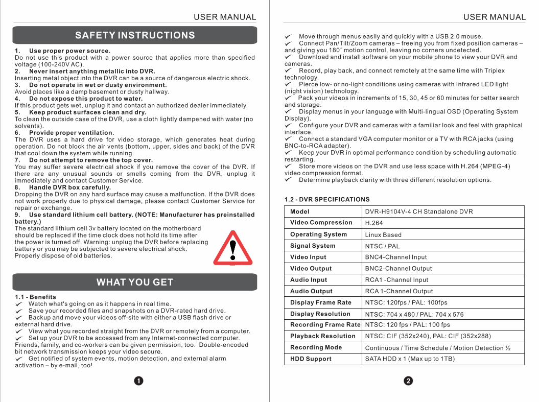
HDD Support SATA HDD x 1 (Max up to 1TB)
1. Use proper power source. Do not use this product with a power source that applies more than specified voltage (100-240V AC). 2. Never insert anything metallic into DVR. Inserting metal object into the DVR can be a source of dangerous electric shock.3. Do not operate in wet or dusty environment. Avoid places like a damp basement or dusty hallway. 4. Do not expose this product to water.If this product gets wet, unplug it and contact an authorized dealer immediately. 5. Keep product surfaces clean and dry. To clean the outside case of the DVR, use a cloth lightly dampened with water (no solvents). 6. Provide proper ventilation. The DVR uses a hard drive for video storage, which generates heat during operation. Do not block the air vents (bottom, upper, sides and back) of the DVR that cool down the system while running. 7. Do not attempt to remove the top cover. You may suffer severe electrical shock if you remove the cover of the DVR. If there are any unusual sounds or smells coming from the DVR, unplug it immediately and contact Customer Service.8. Handle DVR box carefully. Dropping the DVR on any hard surface may cause a malfunction. If the DVR does not work properly due to physical damage, please contact Customer Service for repair or exchange. 9. Use standard lithium cell battery. (NOTE: Manufacturer has preinstalled battery.)The standard lithium cell 3v battery located on the motherboard should be replaced if the time clock does not hold its time after the power is turned off. Warning: unplug the DVR before replacing battery or you may be subjected to severe electrical shock. Properly dispose of old batteries.
SAFETY INSTRUCTIONS
WHAT YOU GET
1.1 - Benefits Watch what's going on as it happens in real time. Save your recorded files and snapshots on a DVR-rated hard drive. Backup and move your videos off-site with either a USB flash drive or external hard drive. View what you recorded straight from the DVR or remotely from a computer. Set up your DVR to be accessed from any Internet-connected computer. Friends, family, and co-workers can be given permission, too. Double-encoded bit network transmission keeps your video secure. Get notified of system events, motion detection, and external alarm activation – by e-mail, too!
Move through menus easily and quickly with a USB 2.0 mouse.Connect Pan/Tilt/Zoom cameras – freeing you from fixed position cameras –
and giving you 180˚ motion control, leaving no corners undetected.Download and install software on your mobile phone to view your DVR and
cameras. Record, play back, and connect remotely at the same time with Triplex
technology.Pierce low- or no-light conditions using cameras with Infrared LED light
(night vision) technology. Pack your videos in increments of 15, 30, 45 or 60 minutes for better search and storage.
Display menus in your language with Multi-lingual OSD (Operating System Display).
Configure your DVR and cameras with a familiar look and feel with graphical interface.
Connect a standard VGA computer monitor or a TV with RCA jacks (using BNC-to-RCA adapter).
Keep your DVR in optimal performance condition by scheduling automatic restarting.
Store more videos on the DVR and use less space with H.264 (MPEG-4) video compression format.
Determine playback clarity with three different resolution options.
1.2 - DVR SPECIFICATIONS
Model
Video Compression
Operating System
Signal System
Video Input
Video Output
Audio Input
Audio Output
Display Frame Rate
Display Resolution
Recording Frame Rate
Recording Mode
Playback Resolution
DVR-H9104V-4 CH Standalone DVR
H.264
Linux Based
NTSC / PAL
BNC4-Channel Input
BNC2-Channel Output
RCA1 -Channel Input
RCA 1-Channel Output
NTSC: 120fps / PAL: 100fps
NTSC: 704 x 480 / PAL: 704 x 576
NTSC: 120 fps / PAL: 100 fps
NTSC: CIF (352x240), PAL: CIF (352x288)
Continuous / Time Schedule / Motion Detection ½
2
USER MANUALUSER MANUAL
USER MANUALUSER MANUAL
2 – DVR PANELS AND CONTROLS
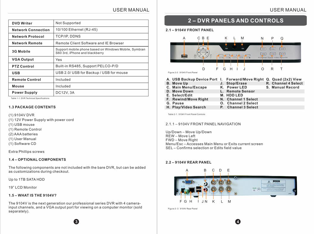
2.1 – 9104V FRONT PANEL
A
F G H I J
L
A. USB Backup Device PortB. Move UpC. Main Menu/EscapeD. Move DownE. Select/EditF. Rewind/Move RightG. PauseH. Play/Video Search
I. Forward/Move RightJ. Stop/EraseK. Power LEDL. Remote SensorM. HDD LEDN. Channel 1 SelectO. Channel 2 SelectP. Channel 3 Select
Q. Quad (2x2) ViewR. Channel 4 SelectS. Manual Record
Figure 2- : 9104V Front Panel2
Table 2-1: 9104V Front Panel Controls
DVD Writer
Network Connection
Network Protocol
Network Remote
Not Supported
10/100 Ethernet (RJ-45)
TCP/IP, DDNS
Remote Client Software and IE Browser
3G MobileSupport mobile phone based on Windows Mobile, SymbianS60 3rd, iPhone and blackberry
VGA Output Yes
PTZ Control
USB
Remote Control
Mouse
Power Supply
Built-in RS485, Support PELCO-P/D
USB 2.0/ USB for Backup / USB for mouse
Included
Included
DC12V, 3A
Table 1-1: DVR Technical Specifications
1.3 PACKAGE CONTENTS
(1) 9104V DVR
(1) 12V Power Supply with power cord
(1) USB mouse
(1) Remote Control
(2) AAA batteries
(1) User Manual
(1) Software CD
Extra Phillips screws
1.4 – OPTIONAL COMPONENTS
The following components are not included with the bare DVR, but can be added as customizations during checkout.
Up to 1TB SATA HDD
19” LCD Monitor
1.5 – WHAT IS THE 9104V?
The 9104V is the next generation our professional series DVR with 4 camera-input channels, and a VGA output port for viewing on a computer monitor (sold separately).
N
O
2.1.1 – 9104V FRONT PANEL NAVIGATION
Up/Down – Move Up/DownREW – Move LeftFWD – Move RightMenu/Esc – Accesses Main Menu or Exits current screenSEL – Confirms selection or Edits field value
2.2 – 9104V REAR PANEL
A B C D E
H I J N K MLGF
Figure 2- 3: 9104V Rear Panel
3 4
C B E
D R T
K M P Q
USER MANUALUSER MANUAL
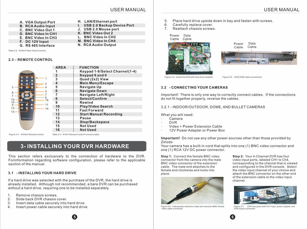
A. VGA Output PortB. RCA Audio InputC. BNC Video Out 1D. BNC Video In CH1E. BNC Video In CH3F. DC 12V InputG. RS 485 Interface
H. LAN/Ethernet portI. USB 2.0 Backup Device PortJ. USB 2.0 Mouse portK. BNC Video Out 2L. BNC Video In CH2M. BNC Video In CH4N. RCA Audio Output
Table 2-2: 9104UV Rear Panel Controls
2.3 – REMOTE CONTROL
Figure 2-4: 9104UV Remote Control Table 2-3: 9104V Remote Control Functions table
3- INSTALLING YOUR DVR HARDWARE
This section refers exclusively to the connection of hardware to the DVR. Forinformation regarding software configuration, please refer to the applicable section of the manual.
1. Remove chassis screws.2. Slide back DVR chassis cover.3. Insert data cable securely into hard drive.4. Insert power cable securely into hard drive.
Data Cable
PowerCable
Figure 3-5: Inside the DVR with hard drive installed
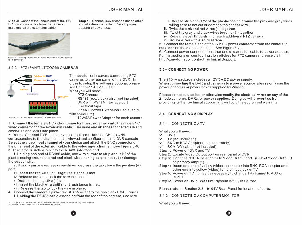
3.2 - CONNECTING YOUR CAMERAS
3.2.1 - INDOOR/OUTDOOR, DOME, AND BULLET CAMERAS
What you will need:· Camera· DVR· Video + Power Extension Cable· 12V Power Adapter or Power Box
Important! Do not use any other power sources other than those provided by ZmodoYour camera has a built-in cord that splits into one (1) BNC video connector and one (1) RCA 12V DC power connector.
Step 1: Connect the female BNC video connector from the camera into the male BNC video connector of the extension cable. The male end attaches to the female end clockwise and locks into place.
Step 2: Your 4-Channel DVR has four video input ports, labeled CH1 to Ch4, corresponding to the channel that is viewed and configured in the DVR console. Select the video input channel of your choice and attach the BNC connector on the other end of the extension cable to the video input channel.
Figure 3-6: Video/power extension cable and camera's BNC female video cable connected
Figure 3-7: DVR rear panel with CH1 input, power adapter, and VGA output connected.
1
2
4
57
166
11
14
3
87
15109
12
13
3.1 - INSTALLING YOUR HARD DRIVE
If a hard drive was selected with the purchase of the DVR, the hard drive is already installed. Although not recommended, a bare DVR can be purchased without a hard drive, requiring one to be installed separately.
5. Place hard drive upside down in bay and fasten with screws.6. Carefully replace cover.7. Reattach chassis screws.
Data Cable
PowerCable
Figure 3-6: SATA HDD cable connections
Important! There is only one way to correctly connect cables. If the connections do not fit together properly, reverse the cables.
5 6
AREA FUNCTION1 Keypad 1-8/Select Channel(1-4)2 Keypad 9 and 03 Quad (2x2) View4 Main Menu/Escape5 Navigate Up6 Navigate Down7 Navigate Left/Right8 Select/Confirm9 Rewind10 Play/Video Search11 Fast Forward12 Start Manual Recording13 Pause14 Stop/Backspace15 Not Used16 Not Used
USER MANUALUSER MANUAL
Step 3: Connect the female end of the 12V DC power connector from the camera to male end on the extension cable.
Step 4: Connect power connector on other end of extension cable to Zmodo power adapter or power box.
Figure 3-8: Video/power extension cable and camera's female power cable connected
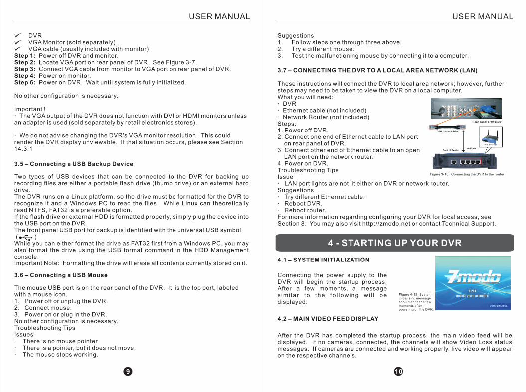
3.2.2 – PTZ (PAN/TILT/ZOOM) CAMERAS
1. Connect the female BNC video connector from the camera into the male BNC video connector of the extension cable. The male end attaches to the female end clockwise and locks into place. 2. Your 4-Channel DVR has four video input ports, labeled CH1 to CH4, corresponding to the channel that is viewed and configured in the DVR console. Select the video input channel of your choice and attach the BNC connector on the other end of the extension cable to the video input channel. See Figure 3-6.3. Insert the RS485 wires into the RS485 interface port. I. Holding one end of RS485 cable, use wire cutters to strip about ½” of the plastic casing around the red and black wires, taking care to not cut or damage the copper wire. ii. Using a pin or eyeglass screwdriver, depress the tab above the positive (+) port. iii. Insert the red wire until slight resistance is met. iv. Release the tab to lock the wire in place. v. Depress the negative (–) tab. vi. Insert the black wire until slight resistance is met. vii. Release the tab to lock the wire in place.
24. Connect the camera's pink/gray RS485 wires to the red/black RS485 wires. I. Holding the RS485 cable extending from the rear of the camera, use wire
cutters to strip about ½” of the plastic casing around the pink and gray wires, taking care to not cut or damage the copper wire. ii. Twist the pink and red wires (+) together. iii. Twist the gray and black wires together (-) together. iv. Repeat steps i through iii for each additional PTZ camera. v. Secure wires with electrical tape.5. Connect the female end of the 12V DC power connector from the camera to male end on the extension cable. See Figure 3-7.6. Connect power connector on other end of extension cable to power adapter. For instructions on configuring dip switches for PTZ cameras, please visit http://zmodo.net or contact Technical Support.
The 9104V package includes a 12V/3A DC power supply.When connecting the DVR and cameras to a power source, please only use the power adapters or power boxes supplied by Zmodo.
Please do not cut, splice, or otherwise modify the electrical wires on any of the Zmodo cameras, DVRs, or power supplies. Doing so will prevent us from providing further technical support and will void the equipment warranty.
3.3 – CONNECTING POWER
3.4 – CONNECTING A DISPLAY
3.4.1 – CONNECTING A TV
What you will need: DVR TV (not included) BNC to RCA Adapter (sold separately) RCA A/V cable (not included)Step 1: Power off DVR and TV.Step 2: Locate Video Output port on rear panel of DVR.Step 3: Connect BNC-RCA adapter to Video Output port. (Select Video Output 1 as primary output.) Step 4: Insert one end of yellow (video) connector into BNC-RCA adapter and other end into yellow (video) female input jack of TV.Step 5: Power on TV. It may be necessary to change TV channel to AUX or INPUT.Step 6: Power on DVR. Wait until system is fully initialized.
Please refer to Section 2.2 – 9104V Rear Panel for location of ports.
3.4.2 – CONNECTING A COMPUTER MONITOR
What you will need:
1Figure 3-9: Connecting PTZ camera to RS485 Interface
1.This figure is only a representation. Actual RS485 inputs and wire colors may differ slightly. 2.Camera's RS485 wire colors differ by make and model.
7 8
This section only covers connecting PTZ cameras to the rear panel of the DVR. In order to setup the software options, please see Section11-PTZ SETUP.What you will need:· PTZ Camera· RS485 (red/black) wire (not included)· DVR with RS485 interface port· Electrical tape· Video + Power Extension Cable (sold with some kits)· 12V/5A Power Adapter for each camera
DVR VGA Monitor (sold separately)VGA cable (usually included with monitor)
Step 1: Power off DVR and monitor.Step 2: Locate VGA port on rear panel of DVR. See Figure 3-7.Step 3: Connect VGA cable from monitor to VGA port on rear panel of DVR. Step 4: Power on monitor. Step 6: Power on DVR. Wait until system is fully initialized.
No other configuration is necessary.
Important !· The VGA output of the DVR does not function with DVI or HDMI monitors unless an adapter is used (sold separately by retail electronics stores).
· We do not advise changing the DVR's VGA monitor resolution. This could render the DVR display unviewable. If that situation occurs, please see Section 14.3.1
3.7 – CONNECTING THE DVR TO A LOCAL AREA NETWORK (LAN)
These instructions will connect the DVR to local area network; however, further steps may need to be taken to view the DVR on a local computer.What you will need:· DVR· Ethernet cable (not included)· Network Router (not included)Steps:1. Power off DVR.2. Connect one end of Ethernet cable to LAN port on rear panel of DVR.3. Connect other end of Ethernet cable to an open LAN port on the network router.4. Power on DVR.Troubleshooting TipsIssue· LAN port lights are not lit either on DVR or network router.Suggestions· Try different Ethernet cable.· Reboot DVR.· Reboot router.For more information regarding configuring your DVR for local access, see Section 8. You may also visit http://zmodo.net or contact Technical Support.
Suggestions1. Follow steps one through three above.2. Try a different mouse.3. Test the malfunctioning mouse by connecting it to a computer.
The mouse USB port is on the rear panel of the DVR. It is the top port, labeled with a mouse icon.1. Power off or unplug the DVR.2. Connect mouse.3. Power on or plug in the DVR.No other configuration is necessary.Troubleshooting TipsIssues· There is no mouse pointer· There is a pointer, but it does not move.· The mouse stops working.
Figure 3-10: Connecting the DVR to the router
4 - STARTING UP YOUR DVR
4.1 – SYSTEM INITIALIZATION
Connecting the power supply to the DVR will begin the startup process. After a few moments, a message s imi lar to the fo l lowing wi l l be displayed:
4.2 – MAIN VIDEO FEED DISPLAY
After the DVR has completed the startup process, the main video feed will be displayed. If no cameras, connected, the channels will show Video Loss status messages. If cameras are connected and working properly, live video will appear on the respective channels.
3.5 – Connecting a USB Backup Device
Two types of USB devices that can be connected to the DVR for backing up recording files are either a portable flash drive (thumb drive) or an external hard drive.The DVR runs on a Linux platform, so the drive must be formatted for the DVR to recognize it and a Windows PC to read the files. While Linux can theoretically read NTFS, FAT32 is a preferable option.If the flash drive or external HDD is formatted properly, simply plug the device into the USB port on the DVR.The front panel USB port for backup is identified with the universal USB symbol ( )While you can either format the drive as FAT32 first from a Windows PC, you may also format the drive using the USB format command in the HDD Management console.Important Note: Formatting the drive will erase all contents currently stored on it.
3.6 – Connecting a USB Mouse
Rear panel of 9104UV
Figure 4-12: System initializing message should appear a few moments after powering on the DVR.
9 10
USER MANUALUSER MANUAL
USER MANUALUSER MANUAL
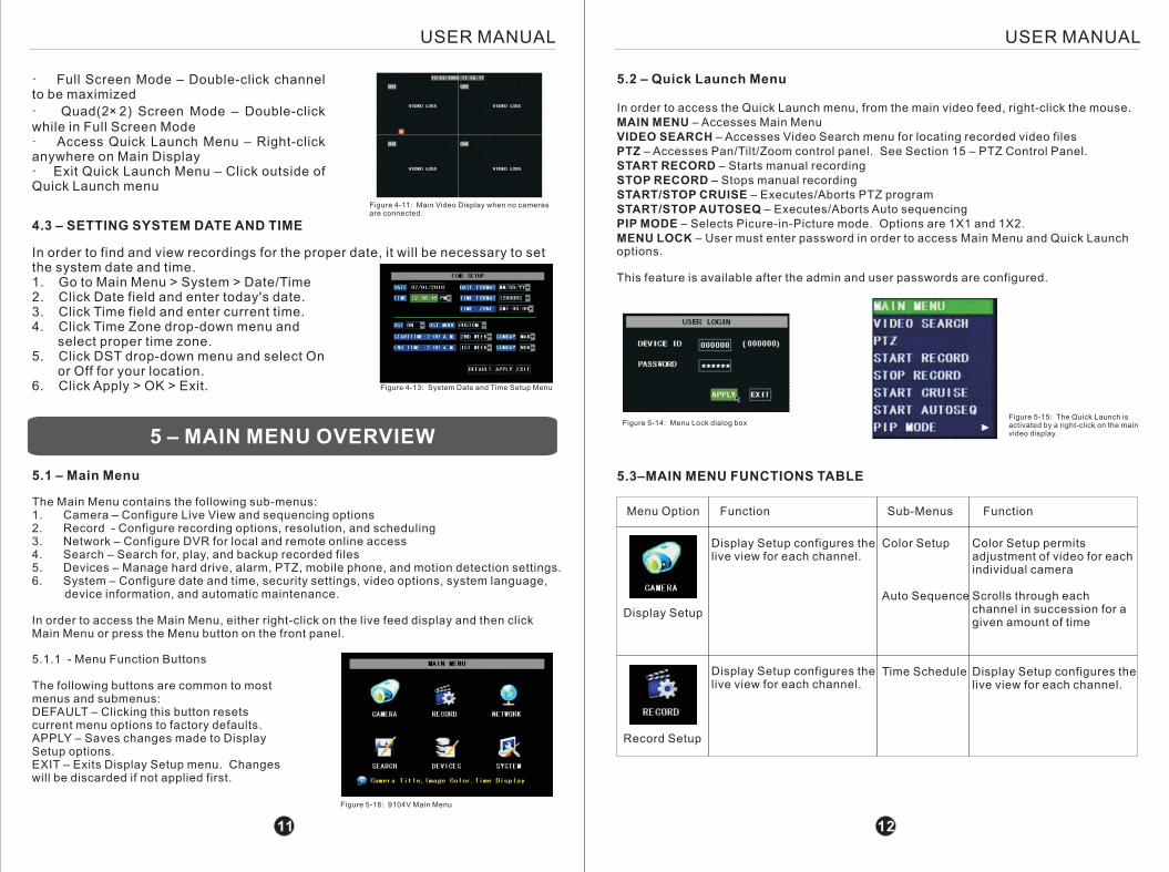
5.1 – Main Menu
The Main Menu contains the following sub-menus:1. Camera – Configure Live View and sequencing options2. Record - Configure recording options, resolution, and scheduling3. Network – Configure DVR for local and remote online access4. Search – Search for, play, and backup recorded files5. Devices – Manage hard drive, alarm, PTZ, mobile phone, and motion detection settings.6. System – Configure date and time, security settings, video options, system language, device information, and automatic maintenance.
In order to access the Main Menu, either right-click on the live feed display and then click Main Menu or press the Menu button on the front panel.
4.3 – SETTING SYSTEM DATE AND TIME
In order to find and view recordings for the proper date, it will be necessary to set the system date and time.1. Go to Main Menu > System > Date/Time2. Click Date field and enter today's date.3. Click Time field and enter current time.4. Click Time Zone drop-down menu and select proper time zone.5. Click DST drop-down menu and select On or Off for your location.6. Click Apply > OK > Exit. Figure 4-13: System Date and Time Setup Menu
Figure 5-16: 9104V Main Menu
· Full Screen Mode – Double-click channel to be maximized
· Quad(2× 2) Screen Mode – Double-click while in Full Screen Mode· Access Quick Launch Menu – Right-click anywhere on Main Display· Exit Quick Launch Menu – Click outside of Quick Launch menu
5 – MAIN MENU OVERVIEWFigure 5-14: Menu Lock dialog box
5.3–MAIN MENU FUNCTIONS TABLE
5.1.1 - Menu Function Buttons
The following buttons are common to most menus and submenus:DEFAULT – Clicking this button resets current menu options to factory defaults.APPLY – Saves changes made to Display Setup options.EXIT – Exits Display Setup menu. Changes will be discarded if not applied first.
5.2 – Quick Launch Menu
In order to access the Quick Launch menu, from the main video feed, right-click the mouse.MAIN MENU – Accesses Main MenuVIDEO SEARCH – Accesses Video Search menu for locating recorded video filesPTZ – Accesses Pan/Tilt/Zoom control panel. See Section 15 – PTZ Control Panel.START RECORD – Starts manual recordingSTOP RECORD – Stops manual recordingSTART/STOP CRUISE – Executes/Aborts PTZ programSTART/STOP AUTOSEQ – Executes/Aborts Auto sequencingPIP MODE – Selects Picure-in-Picture mode. Options are 1X1 and 1X2.MENU LOCK – User must enter password in order to access Main Menu and Quick Launch options.
This feature is available after the admin and user passwords are configured.
Figure 5-15: The Quick Launch is activated by a right-click on the main video display.
Menu Option Sub-MenusFunction Function
Display Setup
Display Setup configures the live view for each channel.
Color Setup permits adjustment of video for each individual camera
Scrolls through each channel in succession for a given amount of time
Color Setup
Auto Sequence
Record Setup
Display Setup configures the live view for each channel.
Display Setup configures the live view for each channel.
Time Schedule
11 12
Figure 4-11: Main Video Display when no cameras are connected.
USER MANUALUSER MANUAL
Netword Setup
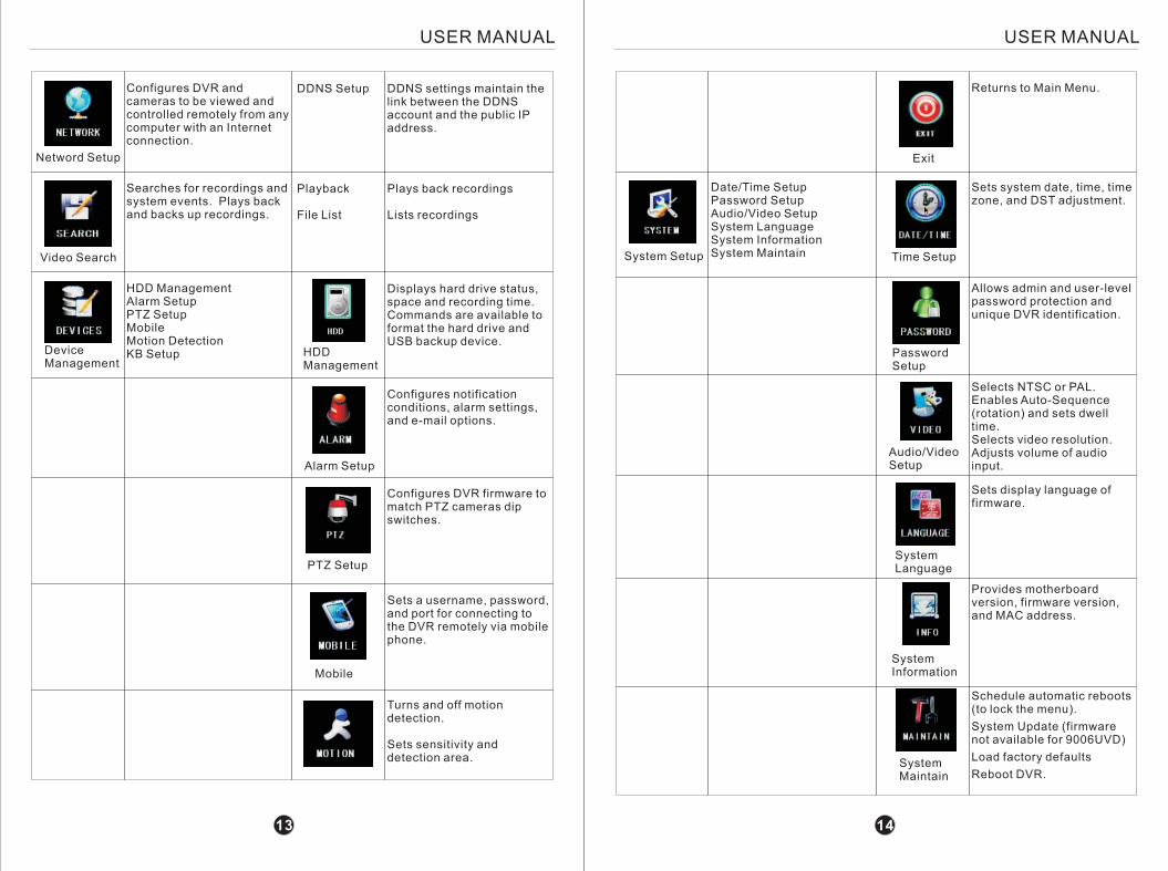
Configures DVR and cameras to be viewed and controlled remotely from any computer with an Internet connection.
DDNS settings maintain the link between the DDNS account and the public IP address.
DDNS Setup
Video Search
Searches for recordings and system events. Plays back and backs up recordings.
Plays back recordings
Lists recordings
Playback
File List
DeviceManagement
HDD ManagementAlarm SetupPTZ SetupMobileMotion DetectionKB Setup
Displays hard drive status, space and recording time. Commands are available to format the hard drive and USB backup device.
HDD Management
Configures notification conditions, alarm settings, and e-mail options.
Alarm Setup
Configures DVR firmware to match PTZ cameras dip switches.
PTZ Setup
Sets a username, password, and port for connecting to the DVR remotely via mobile phone.
Mobile
Turns and off motion detection.
Sets sensitivity and detection area.
Returns to Main Menu.
Exit
Sets system date, time, time zone, and DST adjustment.
Time Setup
Selects NTSC or PAL.Enables Auto-Sequence (rotation) and sets dwell time.Selects video resolution.Adjusts volume of audio input.
Sets display language of firmware.
System Language
Provides motherboard version, firmware version, and MAC address.
System Information
Schedule automatic reboots (to lock the menu).
System Update (firmware not available for 9006UVD)
Load factory defaults
Reboot DVR.System Maintain
Allows admin and user-level password protection and unique DVR identification.
Password Setup
System Setup
Date/Time SetupPassword SetupAudio/Video SetupSystem LanguageSystem Information System Maintain
Audio/Video Setup
13 14
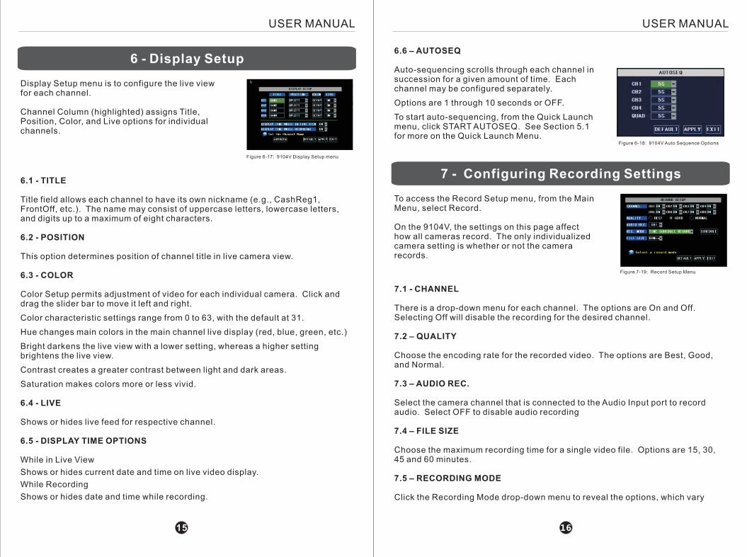
7 - Configuring Recording Settings
USER MANUALUSER MANUAL
6 - Display Setup
Display Setup menu is to configure the live view for each channel.
Channel Column (highlighted) assigns Title, Position, Color, and Live options for individual channels.
Figure 6-17: 9104V Display Setup menu
6.1 - TITLE
Title field allows each channel to have its own nickname (e.g., CashReg1, FrontOff, etc.). The name may consist of uppercase letters, lowercase letters, and digits up to a maximum of eight characters.
6.2 - POSITION
This option determines position of channel title in live camera view.
6.3 - COLOR
Color Setup permits adjustment of video for each individual camera. Click and drag the slider bar to move it left and right.
Color characteristic settings range from 0 to 63, with the default at 31.
Hue changes main colors in the main channel live display (red, blue, green, etc.)
Bright darkens the live view with a lower setting, whereas a higher setting brightens the live view.
Contrast creates a greater contrast between light and dark areas.
Saturation makes colors more or less vivid.
6.4 - LIVE
Shows or hides live feed for respective channel.
6.5 - DISPLAY TIME OPTIONS
While in Live View
Shows or hides current date and time on live video display.
While Recording
Shows or hides date and time while recording.
6.6 – AUTOSEQ
Auto-sequencing scrolls through each channel in succession for a given amount of time. Each channel may be configured separately.
Options are 1 through 10 seconds or OFF.
To start auto-sequencing, from the Quick Launch menu, click START AUTOSEQ. See Section 5.1 for more on the Quick Launch Menu.
16
Figure 6-18: 9104V Auto Sequence Options
7.1 - CHANNEL
There is a drop-down menu for each channel. The options are On and Off. Selecting Off will disable the recording for the desired channel.
7.2 – QUALITY
Choose the encoding rate for the recorded video. The options are Best, Good, and Normal.
7.3 – AUDIO REC.
Select the camera channel that is connected to the Audio Input port to record audio. Select OFF to disable audio recording
7.4 – FILE SIZE
Choose the maximum recording time for a single video file. Options are 15, 30, 45 and 60 minutes.
7.5 – RECORDING MODE
Click the Recording Mode drop-down menu to reveal the options, which vary
15
Figure 7-19: Record Setup Menu
To access the Record Setup menu, from the Main Menu, select Record.
On the 9104V, the settings on this page affect how all cameras record. The only individualized camera setting is whether or not the camera records.
USER MANUALUSER MANUAL
setting, the DVR local IP address may change from time to time.
PPPoE is used for certain DSL Internet providers. A username and password is required to establish a connection to the Internet. Contact your Internet Service Provider (ISP) for more information. Selecting this network type will prompt for the PPPoE name and password.
8.2 – MEDIA PORT
The Media Port is used for connecting to the DVR using the Netviewer software. Generally, the default port 9000 does not need to be changed.
There will need to be a port forwarding rule configured on the router to forward inbound traffic on port 9000 to the local address of the router.
Note: The media port must be defined on the DVR and forwarded on the router in order for remote access to function.
8.3 – WEB PORT
The purpose of the Web Port is to allow access to the DVR via Internet Explorer. The default value is 80, which is the http port standard.
Typically it is not necessary to change this value unless the ISP blocks port 80.
A port forwarding rule must be created for the web port.
8.4 – IP ADDRESS
This field displays the local IP address of the DVR. The factory default value is 192.168.1.100.
This is to be modified to a user-selected value according to the address rules of the DHCP server (typically the router). Check the router for address range.
8.5 – SUBNET MASK
This field displays the Subnet Mask of the LAN (local area network). While the value rarely needs to be changed, it must be matched with the correct address of the network.
8.6 – GATEWAY
The Gateway value is the local address of the router to which the DVR is connected. The default value is 192.168.1.1.
8.7 – DNS
DNS, or Domain Name Server, should also be set to the local address of the router.
1817
slightly by DVR model.
Always
When Recording Mode is set to Always, all channels enabled will record continuously until turned off.
Time Schedule Record
When Recording Mode is set to Schedule, a SCHEDULE button will appear to the right of the menu.
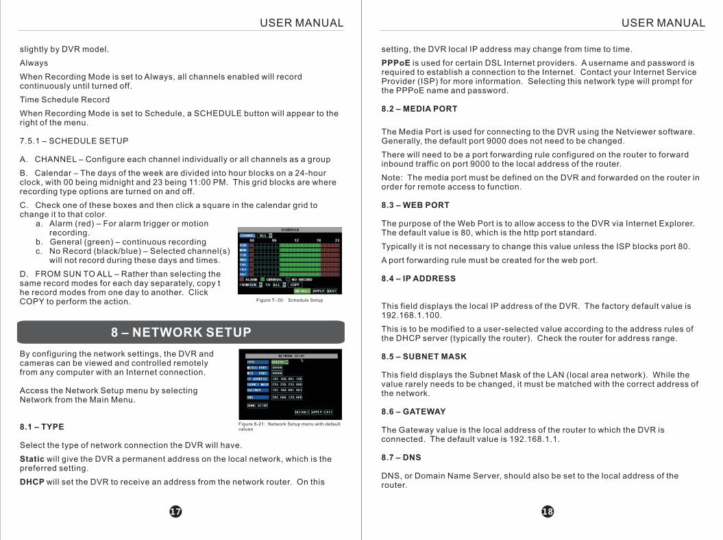
7.5.1 – SCHEDULE SETUP
A. CHANNEL – Configure each channel individually or all channels as a group
B. Calendar – The days of the week are divided into hour blocks on a 24-hour clock, with 00 being midnight and 23 being 11:00 PM. This grid blocks are where recording type options are turned on and off.
C. Check one of these boxes and then click a square in the calendar grid to change it to that color. a. Alarm (red) – For alarm trigger or motion recording. b. General (green) – continuous recording c. No Record (black/blue) – Selected channel(s) will not record during these days and times.
D. FROM SUN TO ALL – Rather than selecting the same record modes for each day separately, copy the record modes from one day to another. ClickCOPY to perform the action.
Figure 7- 20: Schedule Setup
8.1 – TYPE
Select the type of network connection the DVR will have.
Static will give the DVR a permanent address on the local network, which is the preferred setting.
DHCP will set the DVR to receive an address from the network router. On this
8 – NETWORK SETUP
By configuring the network settings, the DVR and cameras can be viewed and controlled remotely from any computer with an Internet connection.
Access the Network Setup menu by selecting Network from the Main Menu.
Figure 8-21: Network Setup menu with default values
USER MANUALUSER MANUAL
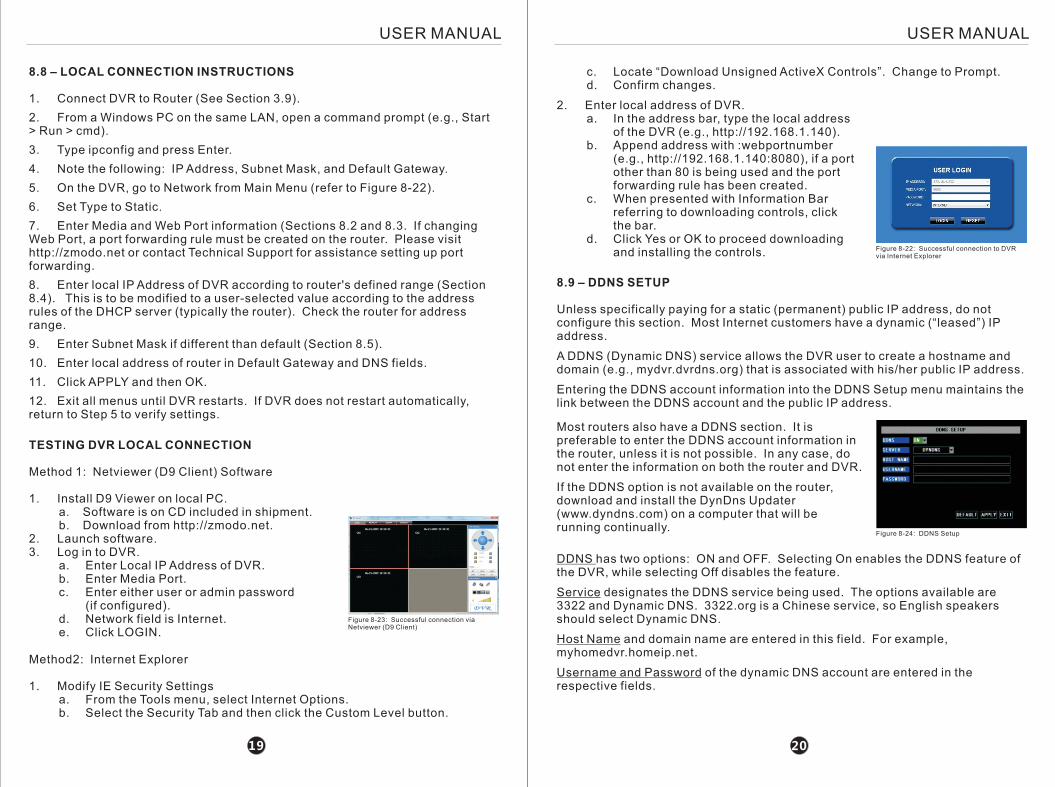
c. Locate “Download Unsigned ActiveX Controls”. Change to Prompt. d. Confirm changes.
2. Enter local address of DVR. a. In the address bar, type the local address of the DVR (e.g., http://192.168.1.140). b. Append address with :webportnumber (e.g., http://192.168.1.140:8080), if a port other than 80 is being used and the port forwarding rule has been created. c. When presented with Information Bar referring to downloading controls, click the bar. d. Click Yes or OK to proceed downloading and installing the controls. Figure 8-22: Successful connection to DVR
via Internet Explorer
2019
8.8 – LOCAL CONNECTION INSTRUCTIONS
1. Connect DVR to Router (See Section 3.9).
2. From a Windows PC on the same LAN, open a command prompt (e.g., Start > Run > cmd).
3. Type ipconfig and press Enter.
4. Note the following: IP Address, Subnet Mask, and Default Gateway.
5. On the DVR, go to Network from Main Menu (refer to Figure 8-22).
6. Set Type to Static.
7. Enter Media and Web Port information (Sections 8.2 and 8.3. If changing Web Port, a port forwarding rule must be created on the router. Please visit http://zmodo.net or contact Technical Support for assistance setting up port forwarding.
8. Enter local IP Address of DVR according to router's defined range (Section 8.4). This is to be modified to a user-selected value according to the address rules of the DHCP server (typically the router). Check the router for address range.
9. Enter Subnet Mask if different than default (Section 8.5).
10. Enter local address of router in Default Gateway and DNS fields.
11. Click APPLY and then OK.
12. Exit all menus until DVR restarts. If DVR does not restart automatically, return to Step 5 to verify settings.
TESTING DVR LOCAL CONNECTION
Method 1: Netviewer (D9 Client) Software
1. Install D9 Viewer on local PC. a. Software is on CD included in shipment. b. Download from http://zmodo.net.2. Launch software.3. Log in to DVR. a. Enter Local IP Address of DVR. b. Enter Media Port. c. Enter either user or admin password (if configured). d. Network field is Internet. e. Click LOGIN.
Figure 8-23: Successful connection via Netviewer (D9 Client)
8.9 – DDNS SETUP
Unless specifically paying for a static (permanent) public IP address, do not configure this section. Most Internet customers have a dynamic (“leased”) IP address.
A DDNS (Dynamic DNS) service allows the DVR user to create a hostname and domain (e.g., mydvr.dvrdns.org) that is associated with his/her public IP address.
Entering the DDNS account information into the DDNS Setup menu maintains the link between the DDNS account and the public IP address.
Method2: Internet Explorer
1. Modify IE Security Settings a. From the Tools menu, select Internet Options. b. Select the Security Tab and then click the Custom Level button.
Most routers also have a DDNS section. It is preferable to enter the DDNS account information in the router, unless it is not possible. In any case, do not enter the information on both the router and DVR.
If the DDNS option is not available on the router, download and install the DynDns Updater (www.dyndns.com) on a computer that will be running continually.
Figure 8-24: DDNS Setup
DDNS has two options: ON and OFF. Selecting On enables the DDNS feature of the DVR, while selecting Off disables the feature.
Service designates the DDNS service being used. The options available are 3322 and Dynamic DNS. 3322.org is a Chinese service, so English speakers should select Dynamic DNS.
Host Name and domain name are entered in this field. For example, myhomedvr.homeip.net.
Username and Password of the dynamic DNS account are entered in the respective fields.
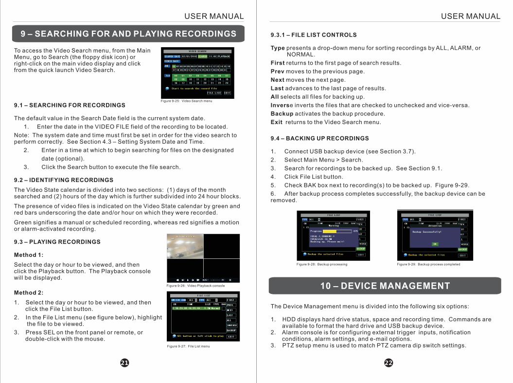
Figure 9-27: File List menu
USER MANUALUSER MANUAL
9.3.1 – FILE LIST CONTROLS
Type presents a drop-down menu for sorting recordings by ALL, ALARM, or NORMAL.
First returns to the first page of search results.
Prev moves to the previous page.
Next moves the next page.
Last advances to the last page of results.
All selects all files for backing up.
Inverse inverts the files that are checked to unchecked and vice-versa.
Backup activates the backup procedure.
Exit returns to the Video Search menu.
9.4 – BACKING UP RECORDINGS
1. Connect USB backup device (see Section 3.7).
2. Select Main Menu > Search.
3. Search for recordings to be backed up. See Section 9.1.
4. Click File List button.
5. Check BAK box next to recording(s) to be backed up. Figure 9-29.
6. After backup process completes successfully, the backup device can be removed.
Figure 9-25: Video Search menu
9 – SEARCHING FOR AND PLAYING RECORDINGS
To access the Video Search menu, from the Main Menu, go to Search (the floppy disk icon) or right-click on the main video display and click from the quick launch Video Search.
9.1 – SEARCHING FOR RECORDINGS
The default value in the Search Date field is the current system date.
1. Enter the date in the VIDEO FILE field of the recording to be located.
Note: The system date and time must first be set in order for the video search to perform correctly. See Section 4.3 – Setting System Date and Time.
2. Enter in a time at which to begin searching for files on the designated
date (optional).
3. Click the Search button to execute the file search.
9.2 – IDENTIFYING RECORDINGS
The Video State calendar is divided into two sections: (1) days of the month searched and (2) hours of the day which is further subdivided into 24 hour blocks.
The presence of video files is indicated on the Video State calendar by green and red bars underscoring the date and/or hour on which they were recorded.
Green signifies a manual or scheduled recording, whereas red signifies a motion or alarm-activated recording.
9.3 – PLAYING RECORDINGS
Method 1:
Select the day or hour to be viewed, and then click the Playback button. The Playback console will be displayed.
Method 2:
1. Select the day or hour to be viewed, and then click the File List button.
2. In the File List menu (see figure below), highlight the file to be viewed.
3. Press SEL on the front panel or remote, or double-click with the mouse.
2221
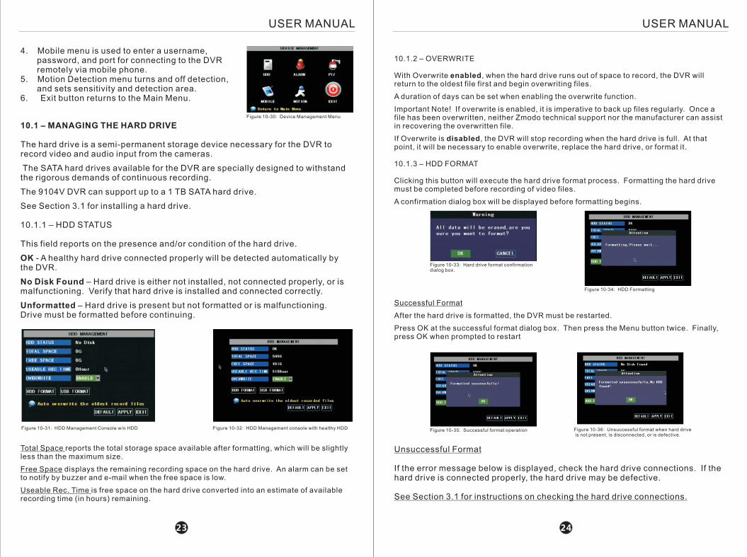
Figure 9-28: Backup processing Figure 9-29: Backup process completed
10 – DEVICE MANAGEMENT
The Device Management menu is divided into the following six options:
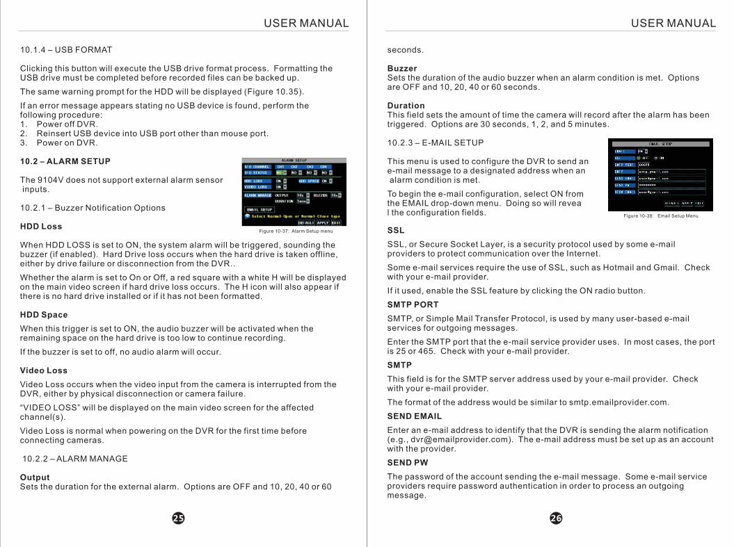
1. HDD displays hard drive status, space and recording time. Commands are available to format the hard drive and USB backup device.2. Alarm console is for configuring external trigger inputs, notification conditions, alarm settings, and e-mail options. 3. PTZ setup menu is used to match PTZ camera dip switch settings.
Figure 9-26: Video Playback console
USER MANUALUSER MANUAL
10.1 – MANAGING THE HARD DRIVE
The hard drive is a semi-permanent storage device necessary for the DVR to record video and audio input from the cameras.
The SATA hard drives available for the DVR are specially designed to withstand the rigorous demands of continuous recording.
The 9104V DVR can support up to a 1 TB SATA hard drive.
See Section 3.1 for installing a hard drive.
10.1.1 – HDD STATUS
This field reports on the presence and/or condition of the hard drive.
OK - A healthy hard drive connected properly will be detected automatically by the DVR.
No Disk Found – Hard drive is either not installed, not connected properly, or is malfunctioning. Verify that hard drive is installed and connected correctly.
Unformatted – Hard drive is present but not formatted or is malfunctioning. Drive must be formatted before continuing.
Figure 10-31: HDD Management Console w/o HDD Figure 10-32: HDD Management console with healthy HDD
10.1.2 – OVERWRITE
With Overwrite enabled, when the hard drive runs out of space to record, the DVR will return to the oldest file first and begin overwriting files.
A duration of days can be set when enabling the overwrite function.
Important Note! If overwrite is enabled, it is imperative to back up files regularly. Once a file has been overwritten, neither Zmodo technical support nor the manufacturer can assist in recovering the overwritten file.
If Overwrite is disabled, the DVR will stop recording when the hard drive is full. At that point, it will be necessary to enable overwrite, replace the hard drive, or format it.
10.1.3 – HDD FORMAT
Clicking this button will execute the hard drive format process. Formatting the hard drive must be completed before recording of video files.
A confirmation dialog box will be displayed before formatting begins.
2423
Figure 10-33: Hard drive format confirmation dialog box.
Figure 10-34: HDD Formatting
Successful Format
After the hard drive is formatted, the DVR must be restarted.
Press OK at the successful format dialog box. Then press the Menu button twice. Finally, press OK when prompted to restart
4. Mobile menu is used to enter a username, password, and port for connecting to the DVR remotely via mobile phone.5. Motion Detection menu turns and off detection, and sets sensitivity and detection area.6. Exit button returns to the Main Menu.
Figure 10-30: Device Management Menu
Total Space reports the total storage space available after formatting, which will be slightly less than the maximum size.
Free Space displays the remaining recording space on the hard drive. An alarm can be set to notify by buzzer and e-mail when the free space is low.
Useable Rec. Time is free space on the hard drive converted into an estimate of available recording time (in hours) remaining.
Figure 10-35: Successful format operation Figure 10-36: Unsuccessful format when hard drive is not present, is disconnected, or is defective.
Unsuccessful Format
If the error message below is displayed, check the hard drive connections. If the hard drive is connected properly, the hard drive may be defective.
See Section 3.1 for instructions on checking the hard drive connections.
USER MANUALUSER MANUAL
2625
10.1.4 – USB FORMAT
Clicking this button will execute the USB drive format process. Formatting the USB drive must be completed before recorded files can be backed up.
The same warning prompt for the HDD will be displayed (Figure 10.35).
If an error message appears stating no USB device is found, perform the following procedure:1. Power off DVR.2. Reinsert USB device into USB port other than mouse port.3. Power on DVR.
10.2 – ALARM SETUP
The 9104V does not support external alarm sensor inputs.
10.2.1 – Buzzer Notification Options
HDD Loss
When HDD LOSS is set to ON, the system alarm will be triggered, sounding the buzzer (if enabled). Hard Drive loss occurs when the hard drive is taken offline, either by drive failure or disconnection from the DVR..
Whether the alarm is set to On or Off, a red square with a white H will be displayed on the main video screen if hard drive loss occurs. The H icon will also appear if there is no hard drive installed or if it has not been formatted.
HDD Space
When this trigger is set to ON, the audio buzzer will be activated when the remaining space on the hard drive is too low to continue recording.
If the buzzer is set to off, no audio alarm will occur.
Video Loss
Video Loss occurs when the video input from the camera is interrupted from the DVR, either by physical disconnection or camera failure.
“VIDEO LOSS” will be displayed on the main video screen for the affected channel(s).
Video Loss is normal when powering on the DVR for the first time before connecting cameras.
10.2.2 – ALARM MANAGE
OutputSets the duration for the external alarm. Options are OFF and 10, 20, 40 or 60
Figure 10-37: Alarm Setup menu
seconds.
BuzzerSets the duration of the audio buzzer when an alarm condition is met. Options are OFF and 10, 20, 40 or 60 seconds.
DurationThis field sets the amount of time the camera will record after the alarm has been triggered. Options are 30 seconds, 1, 2, and 5 minutes.
10.2.3 – E-MAIL SETUP
This menu is used to configure the DVR to send an e-mail message to a designated address when an alarm condition is met.
To begin the e-mail configuration, select ON from the EMAIL drop-down menu. Doing so will reveal the configuration fields. Figure 10-38: Email Setup Menu
SSL
SSL, or Secure Socket Layer, is a security protocol used by some e-mail providers to protect communication over the Internet.
Some e-mail services require the use of SSL, such as Hotmail and Gmail. Check with your e-mail provider.
If it used, enable the SSL feature by clicking the ON radio button.
SMTP PORT
SMTP, or Simple Mail Transfer Protocol, is used by many user-based e-mail services for outgoing messages.
Enter the SMTP port that the e-mail service provider uses. In most cases, the port is 25 or 465. Check with your e-mail provider.
SMTP
This field is for the SMTP server address used by your e-mail provider. Check with your e-mail provider.
The format of the address would be similar to smtp.emailprovider.com.
SEND EMAIL
Enter an e-mail address to identify that the DVR is sending the alarm notification (e.g., [email protected]). The e-mail address must be set up as an account with the provider.
SEND PW
The password of the account sending the e-mail message. Some e-mail service providers require password authentication in order to process an outgoing message.
12 – MOBILE PHONE SETUP
USER MANUALUSER MANUAL
cameras.
Parity
Parity is a method of detecting errors in transmission.
Options are None, Odd, Even, Mark, and Space. The default setting of None should be kept for Zmodo PTZ cameras.
Cruise
With the Cruise setting set to ON, the PTZ camera on the assigned channel can operate automatically after being programmed.
When set to OFF, the camera will not execute its programmed surveillance.
Address
The Address field must match that of camera address dip switch setting.
This DVR supports mobile phone access by the following devices:
a) iPhone™b) Blackberry™ OS V4.7 or laterc) Windows Mobile™ Pro 5.0 and 6.1 OSd) Nokia Symbian S60 3rd Edition (9.1) and S60 5th Edition (9.4)
Important Notes: 1. Ability to connect to DVR via mobile phone in no way constitutes or implies a verbal or written agreement. 2. When using mobile phone access, only one channel may be viewed simultaneously. 3. The video loading time and performance are determined by the connection bandwidth.
Before setting up the mobile phone on the DVR, configure the DVR for network access. See Section 8 – Network Setup, visit http://zmodo.net, or contact Technical Support.
To access the Mobile Phone Setup, from the Main Menu, select Devices > Mobile.
2827
RECV EMAIL
Enter the e-mail address that will receive the alarm notification messages.
11 – PTZ SETUP
This section only covers the software configuration for the PTZ cameras. For guidance on installing the cameras, please see Section 3.2.4 – Connecting Your PTZ Cameras.
For directions on programming the PTZ camera to survey automatically, see Section 15 – PTZ Cruising.
The settings under each channel must match those of the camera's circuit board switches. There are ten switches (0-9), called dip switches, in the camera. For instructions on setting the dip switches, visit http://zmodo.net or contact Technical Support.
Figure 10-39: PTZ Setup Menu
11.1 – OPTIONS
Protocol
Zmodo PTZ cameras use Pelco-D and Pelco-P protocols. These protocols were designed by Pelco. Pelco-D is more common.
Set the protocol to match that of the PTZ camera. The two options are Pelco-D and Pelco-P.
Pelco-P cameras use No parity, 8 Data bits and 1 Stop bit, as do Pelco-D cameras.
Baud Rate
Baud rate is the data transmission speed used for communication between the DVR and PTZ camera. This setting must match the switch on the PTZ camera.
The baud rate options are 1200, 2400, 4800 and 9600.
The default setting of 9600 should be kept for most Zmodo PTZ cameras. Check the specific camera model.
Data Bit
Sets the number of bits used in a character of data.
The options are 5, 6, 7, or 8. The default setting of 8 should be kept for Zmodo PTZ cameras.
Stop Bit
Stop bits sent at the end of every character allow the receiving signal hardware to detect the end of a character.
Options are 1 and 2. The default setting of 1 should be kept for Zmodo PTZ
Figure 12-40: Mobile Setup Menu
12.1 – USER NAME
Enter a username for the user connecting to the DVR via the mobile phone. This is not the same username as the admin or user account either for local or Internet access.
12.2 – USER PASSWORD
3.Please contact Technical Support before attempting to upgrade the DVR firmware.
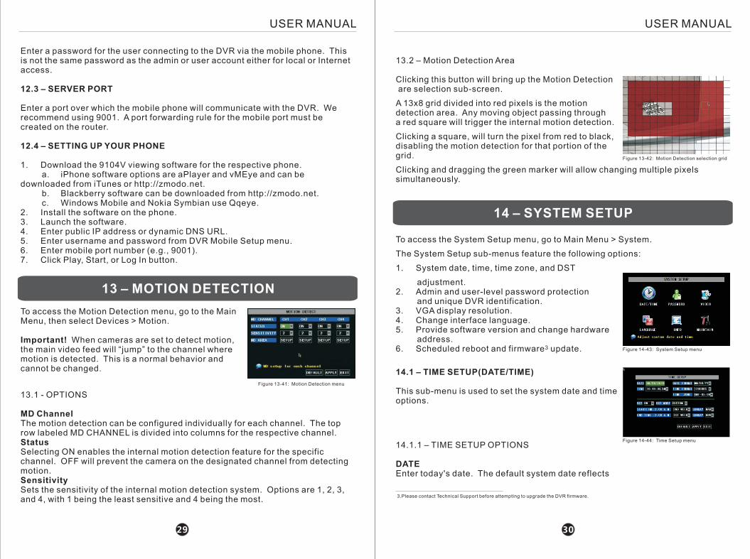
13 – MOTION DETECTION
To access the Motion Detection menu, go to the Main Menu, then select Devices > Motion.
Important! When cameras are set to detect motion, the main video feed will “jump” to the channel where motion is detected. This is a normal behavior and cannot be changed.
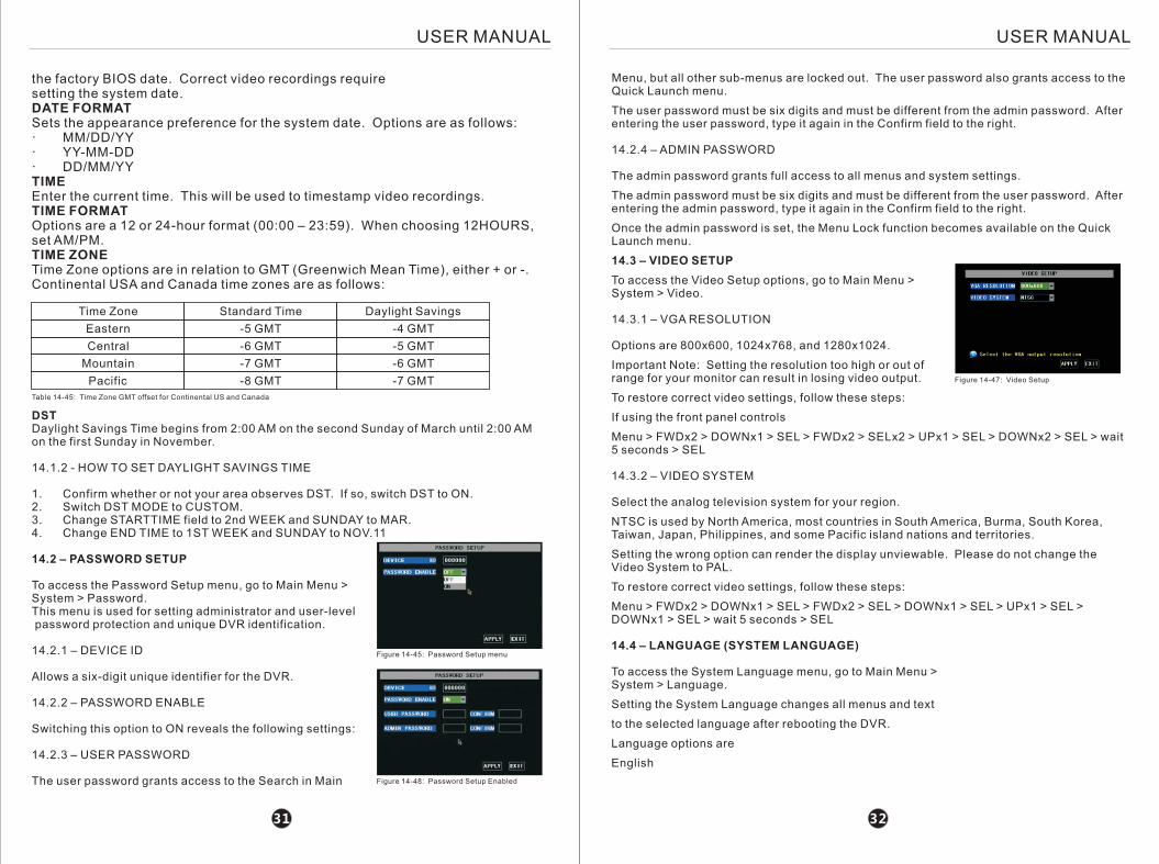
13.2 – Motion Detection Area
Clicking this button will bring up the Motion Detection are selection sub-screen.
A 13x8 grid divided into red pixels is the motion detection area. Any moving object passing through a red square will trigger the internal motion detection.
Clicking a square, will turn the pixel from red to black, disabling the motion detection for that portion of the grid.
Clicking and dragging the green marker will allow changing multiple pixels simultaneously.
Figure 13-42: Motion Detection selection grid
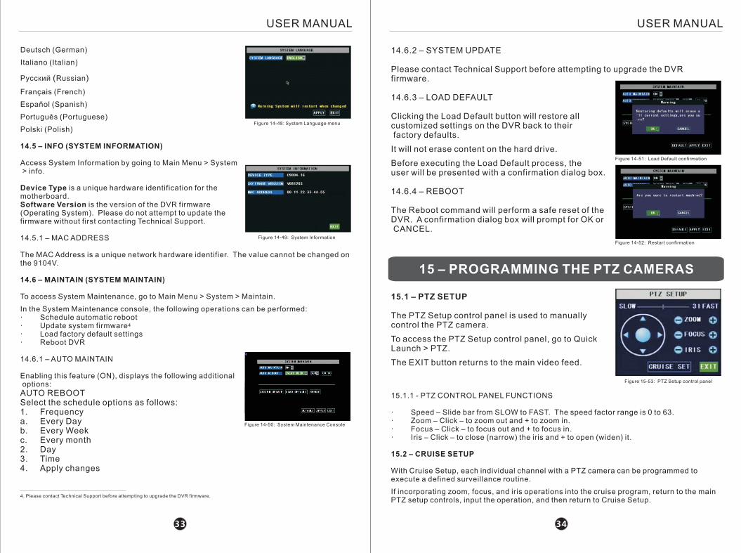
14 – SYSTEM SETUP
To access the System Setup menu, go to Main Menu > System.
The System Setup sub-menus feature the following options:
1. System date, time, time zone, and DST
adjustment.2. Admin and user-level password protection and unique DVR identification.3. VGA display resolution.4. Change interface language.5. Provide software version and change hardware address.
36. Scheduled reboot and firmware update. Figure 14-43: System Setup menu
3029
Enter a password for the user connecting to the DVR via the mobile phone. This is not the same password as the admin or user account either for local or Internet access.
12.3 – SERVER PORT
Enter a port over which the mobile phone will communicate with the DVR. We recommend using 9001. A port forwarding rule for the mobile port must be created on the router.
12.4 – SETTING UP YOUR PHONE
1. Download the 9104V viewing software for the respective phone. a. iPhone software options are aPlayer and vMEye and can be downloaded from iTunes or http://zmodo.net. b. Blackberry software can be downloaded from http://zmodo.net. c. Windows Mobile and Nokia Symbian use Qqeye.2. Install the software on the phone.3. Launch the software.4. Enter public IP address or dynamic DNS URL.5. Enter username and password from DVR Mobile Setup menu.6. Enter mobile port number (e.g., 9001).7. Click Play, Start, or Log In button.
Figure 13-41: Motion Detection menu
USER MANUAL USER MANUAL
13.1 - OPTIONS
MD ChannelThe motion detection can be configured individually for each channel. The top row labeled MD CHANNEL is divided into columns for the respective channel.StatusSelecting ON enables the internal motion detection feature for the specific channel. OFF will prevent the camera on the designated channel from detecting motion.SensitivitySets the sensitivity of the internal motion detection system. Options are 1, 2, 3, and 4, with 1 being the least sensitive and 4 being the most.
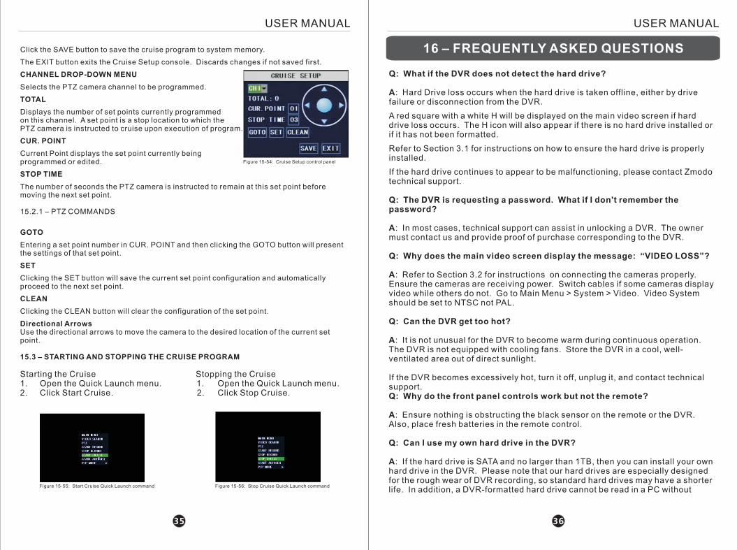
14.1 – TIME SETUP(DATE/TIME)
This sub-menu is used to set the system date and time options.
Figure 14-44: Time Setup menu14.1.1 – TIME SETUP OPTIONS
DATEEnter today's date. The default system date reflects
USER MANUALUSER MANUAL
DSTDaylight Savings Time begins from 2:00 AM on the second Sunday of March until 2:00 AM on the first Sunday in November.
14.1.2 - HOW TO SET DAYLIGHT SAVINGS TIME
1. Confirm whether or not your area observes DST. If so, switch DST to ON.2. Switch DST MODE to CUSTOM.3. Change STARTTIME field to 2nd WEEK and SUNDAY to MAR.4. Change END TIME to 1ST WEEK and SUNDAY to NOV.11
14.2 – PASSWORD SETUP
To access the Password Setup menu, go to Main Menu > System > Password.This menu is used for setting administrator and user-level password protection and unique DVR identification.
14.2.1 – DEVICE ID
Allows a six-digit unique identifier for the DVR.
14.2.2 – PASSWORD ENABLE
Switching this option to ON reveals the following settings:
14.2.3 – USER PASSWORD
The user password grants access to the Search in Main
the factory BIOS date. Correct video recordings require setting the system date.DATE FORMATSets the appearance preference for the system date. Options are as follows:· MM/DD/YY· YY-MM-DD· DD/MM/YYTIMEEnter the current time. This will be used to timestamp video recordings.TIME FORMATOptions are a 12 or 24-hour format (00:00 – 23:59). When choosing 12HOURS, set AM/PM.TIME ZONETime Zone options are in relation to GMT (Greenwich Mean Time), either + or -.Continental USA and Canada time zones are as follows:
Time Zone
Eastern
Central
Mountain
Pacific
Standard Time
-5 GMT
-6 GMT
-7 GMT
-8 GMT
Daylight Savings
-4 GMT
-5 GMT
-6 GMT
-7 GMT
Table 14-45: Time Zone GMT offset for Continental US and Canada
Figure 14-45: Password Setup menu
Menu, but all other sub-menus are locked out. The user password also grants access to the Quick Launch menu.
The user password must be six digits and must be different from the admin password. After entering the user password, type it again in the Confirm field to the right.
14.2.4 – ADMIN PASSWORD
The admin password grants full access to all menus and system settings.
The admin password must be six digits and must be different from the user password. After entering the admin password, type it again in the Confirm field to the right.
Once the admin password is set, the Menu Lock function becomes available on the Quick Launch menu.
14.3 – VIDEO SETUP
To access the Video Setup options, go to Main Menu > System > Video.
14.3.1 – VGA RESOLUTION
Options are 800x600, 1024x768, and 1280x1024.
Important Note: Setting the resolution too high or out of range for your monitor can result in losing video output.
To restore correct video settings, follow these steps:
If using the front panel controls
Menu > FWDx2 > DOWNx1 > SEL > FWDx2 > SELx2 > UPx1 > SEL > DOWNx2 > SEL > wait 5 seconds > SEL
14.3.2 – VIDEO SYSTEM
Select the analog television system for your region.
NTSC is used by North America, most countries in South America, Burma, South Korea, Taiwan, Japan, Philippines, and some Pacific island nations and territories.
Setting the wrong option can render the display unviewable. Please do not change the Video System to PAL.
To restore correct video settings, follow these steps:
Menu > FWDx2 > DOWNx1 > SEL > FWDx2 > SEL > DOWNx1 > SEL > UPx1 > SEL > DOWNx1 > SEL > wait 5 seconds > SEL
14.4 – LANGUAGE (SYSTEM LANGUAGE)
To access the System Language menu, go to Main Menu > System > Language.
Setting the System Language changes all menus and text
to the selected language after rebooting the DVR.
Language options are
English
Figure 14-48: Password Setup Enabled
Figure 14-47: Video Setup
3231
USER MANUALUSER MANUAL
Deutsch (German)
Italiano (Italian)
Русский (Russian)
Français (French)
Español (Spanish)
Português (Portuguese)
Polski (Polish)
14.5 – INFO (SYSTEM INFORMATION)
Access System Information by going to Main Menu > System > info.
Device Type is a unique hardware identification for the motherboard.Software Version is the version of the DVR firmware (Operating System). Please do not attempt to update the firmware without first contacting Technical Support.
14.5.1 – MAC ADDRESS
The MAC Address is a unique network hardware identifier. The value cannot be changed on the 9104V.
14.6 – MAINTAIN (SYSTEM MAINTAIN)
To access System Maintenance, go to Main Menu > System > Maintain.
In the System Maintenance console, the following operations can be performed:· Schedule automatic reboot
4· Update system firmware· Load factory default settings· Reboot DVR
14.6.1 – AUTO MAINTAIN
Enabling this feature (ON), displays the following additional options:AUTO REBOOTSelect the schedule options as follows:1. Frequencya. Every Dayb. Every Week c. Every month2. Day3. Time4. Apply changes
Figure 14-48: System Language menu
14.6.2 – SYSTEM UPDATE
Please contact Technical Support before attempting to upgrade the DVR firmware.
14.6.3 – LOAD DEFAULT
Clicking the Load Default button will restore all customized settings on the DVR back to their factory defaults.
It will not erase content on the hard drive.
Before executing the Load Default process, the user will be presented with a confirmation dialog box.
14.6.4 – REBOOT
The Reboot command will perform a safe reset of the DVR. A confirmation dialog box will prompt for OK or CANCEL.
Figure 14-50: System Maintenance Console
Figure 14-51: Load Default confirmation
3433
Figure 14-49: System Information
4. Please contact Technical Support before attempting to upgrade the DVR firmware.
Figure 14-52: Restart confirmation
15 – PROGRAMMING THE PTZ CAMERAS
15.1 – PTZ SETUP
The PTZ Setup control panel is used to manually control the PTZ camera.
To access the PTZ Setup control panel, go to Quick Launch > PTZ.
The EXIT button returns to the main video feed.
Figure 15-53: PTZ Setup control panel
15.1.1 - PTZ CONTROL PANEL FUNCTIONS
· Speed – Slide bar from SLOW to FAST. The speed factor range is 0 to 63.· Zoom – Click – to zoom out and + to zoom in.· Focus – Click – to focus out and + to focus in.· Iris – Click – to close (narrow) the iris and + to open (widen) it.
15.2 – CRUISE SETUP
With Cruise Setup, each individual channel with a PTZ camera can be programmed to execute a defined surveillance routine.
If incorporating zoom, focus, and iris operations into the cruise program, return to the main PTZ setup controls, input the operation, and then return to Cruise Setup.
USER MANUALUSER MANUAL
Click the SAVE button to save the cruise program to system memory.
The EXIT button exits the Cruise Setup console. Discards changes if not saved first.
CHANNEL DROP-DOWN MENU
Selects the PTZ camera channel to be programmed.
TOTAL
Displays the number of set points currently programmedon this channel. A set point is a stop location to which the PTZ camera is instructed to cruise upon execution of program.
CUR. POINT
Current Point displays the set point currently being programmed or edited.
STOP TIME
The number of seconds the PTZ camera is instructed to remain at this set point before moving the next set point.
15.2.1 – PTZ COMMANDS
GOTO
Entering a set point number in CUR. POINT and then clicking the GOTO button will present the settings of that set point.
SET
Clicking the SET button will save the current set point configuration and automatically proceed to the next set point.
CLEAN
Clicking the CLEAN button will clear the configuration of the set point.
Directional ArrowsUse the directional arrows to move the camera to the desired location of the current set point.
15.3 – STARTING AND STOPPING THE CRUISE PROGRAM
Starting the Cruise Stopping the Cruise1. Open the Quick Launch menu. 1. Open the Quick Launch menu.2. Click Start Cruise. 2. Click Stop Cruise.
Figure 15-54: Cruise Setup control panel
Figure 15-55: Start Cruise Quick Launch command Figure 15-56: Stop Cruise Quick Launch command
3635
Q: What if the DVR does not detect the hard drive?
A: Hard Drive loss occurs when the hard drive is taken offline, either by drive failure or disconnection from the DVR.
A red square with a white H will be displayed on the main video screen if hard drive loss occurs. The H icon will also appear if there is no hard drive installed or if it has not been formatted.
Refer to Section 3.1 for instructions on how to ensure the hard drive is properly installed.
If the hard drive continues to appear to be malfunctioning, please contact Zmodo technical support.
Q: The DVR is requesting a password. What if I don't remember the password?
A: In most cases, technical support can assist in unlocking a DVR. The owner must contact us and provide proof of purchase corresponding to the DVR.
Q: Why does the main video screen display the message: “VIDEO LOSS”?
A: Refer to Section 3.2 for instructions on connecting the cameras properly. Ensure the cameras are receiving power. Switch cables if some cameras display video while others do not. Go to Main Menu > System > Video. Video System should be set to NTSC not PAL.
Q: Can the DVR get too hot?
A: It is not unusual for the DVR to become warm during continuous operation. The DVR is not equipped with cooling fans. Store the DVR in a cool, well-ventilated area out of direct sunlight.
If the DVR becomes excessively hot, turn it off, unplug it, and contact technical support.Q: Why do the front panel controls work but not the remote?
A: Ensure nothing is obstructing the black sensor on the remote or the DVR. Also, place fresh batteries in the remote control.
Q: Can I use my own hard drive in the DVR?
A: If the hard drive is SATA and no larger than 1TB, then you can install your own hard drive in the DVR. Please note that our hard drives are especially designed for the rough wear of DVR recording, so standard hard drives may have a shorter life. In addition, a DVR-formatted hard drive cannot be read in a PC without
16 – FREQUENTLY ASKED QUESTIONS
USER MANUALUSER MANUAL
special Linux software.
Q: Do I have to stop recording in order to play back files?
A: No. The DVR supports simultaneous recording and playback.
Q: Can I erase a certain recording file?
A: The only two methods for erasing files are overwriting the oldest file, with the overwrite function enabled, or formatting the hard drive, which will erase everything.
Q: Why can't I view my DVR online?
A: Settings may be configured incorrectly, or the DVR or local network may be offline.
Q: Why can't I control my PTZ camera?
A: Ensure the PTZ cameras are connected properly to the DVR. See Section 3.2.2.
Ensure the PTZ cameras are configured properly. See Section 11.
Q: Why does the buzzer keep sounding?
A: An alert has been triggered. Motion may have been detected, the hard drive may be low on space or disconnected, or a camera may have lost video. Check your alarm settings. See Section 10.2.
17 – APPENDICES
Zmodo offers its customers free upgrades to the DVR firmware.
Please contact Technical Support for instructions.
Without Zmodo qualified technical support, Zmodo cannot be held responsible for DVR malfunction resulting from improper firmware installation.
3837
17.1 - WARRANTY
All products carry a 1-year warranty unless otherwise indicated. 3 year warranty plan is also available for purchase. Zmodo will, at its sole discretion, replace or repair any products found to be defective during their warranty period. Zmodo will not honor any other warranty, implied or otherwise, including those of merchantability and fitness for a particular purpose.
17.2 – HARDWARE UPGRADE (TRADE-IN) POLICY
Please contact Zmodo for more information.
17.3 – FIRMWARE UPGRADES
![Operating Manual [호환 모드] - DVR Master… · This manual serves basic operation on installation, and operation of DVR ... User who first operates DVR, or is not accustomed](https://img.pdfslide.tips/doc/110x75/5bc001bf09d3f22e7d8d27ba/operating-manual-dvr-this-manual-serves-basic-operation-on.jpg)