Embed Size (px)
Citation preview

ICC’s 2012 Codes and You! January 20, 2012
CRCA 29th Annual Trade Show 1
CRCA’s 29th Annual Trade ShowOakbrook Terrace IL January 20 2012Oakbrook Terrace, IL – January 20, 2012
ICC’s 2012 Codes and You!
Mark S. GrahamAssociate Executive Director Technical ServicesAssociate Executive Director, Technical Services
National Roofing Contractors Association
Caveats
• Some prior knowledge of the code (preferably the 2009 I‐codes) is necessary2009 I codes) is necessary….
Legend
• Italicized text denotes terms defined in the Code
• I am the messenger… Don’t shoot the messenger.
• Underlined text denotes changes to the Code since the 2009 Editions

ICC’s 2012 Codes and You! January 20, 2012
CRCA 29th Annual Trade Show 2
ICC code publication schedule
• 2000 I‐codes
• 2003 I‐codes• 2003 I‐codes
• 2006 I‐codes
• 2009 I‐codes
• 2012 I‐codes:
– Published in Spring 2011– Published in Spring 2011
• 2015 I‐codes:
– Code change proposal submission January 3, 2012
– Published in Spring 2014 (tentative)
International ______ Code (I‐codes)
• Building (IBC) • Fuel Gas• Building (IBC)
• Residential (IRC)
• Fire (IFC)
• Energy Conservation (IECC)
• Plumbing (IPC)
• Private Sewage Disposal
• Fuel Gas
• Wildland‐Urban Interface
• Existing Building (IEBC)
• Property Maintenance (IPMC)
• Zoning (IZC)
• Pool and SpaPrivate Sewage Disposal
• Mechanical (IMC)
Pool and Spa
• Green Construction (IgCC)

ICC’s 2012 Codes and You! January 20, 2012
CRCA 29th Annual Trade Show 3
I t ti l B ildi C dInternational Building Code,2012 Edition (IBC 2012)
International Fire Code,2012 Edition (IFC 2012)2012 Edition (IFC 2012)
Crickets and Saddles2012 IBC, Section 1503.6‐‐Crickets and Saddles
1503.6 Crickets and saddles. A cricket or saddle shall be installed on the ridge side of any chimney or penetration greater than 30 inches (762 mm) wide as measured perpendicular to the slope. Cricket or saddle coverings shall be sheet metal or of the same material as the roof covering.
Exception: Unit skylights installed in accordance with Section 2405.5 and flashed in accordance with the manufacturer’s instructions shall be permitted to be installed without a cricket or saddle.
Tested and labeled as complying with AAMA/WDMA/CSA 101/I.S./A440

ICC’s 2012 Codes and You! January 20, 2012
CRCA 29th Annual Trade Show 4
Edge metal flashingsIBC 2012, Section 1504.5‐‐Edge Securement for Low‐slope Roofs
1504.5 Edge securement for low‐slope roofs. Low‐slope built‐up, modified bitumen and single‐ply roof system metal edge securement, except gutters, shall be designed and installed for wind loads in accordance with Chapter 16 and tested for resistance in accordance with Test Methods RE‐1, RE‐2 and RE‐3 of ANSI/SPRI ES‐1, except V lt wind speed shall be determinedof ANSI/SPRI ES 1, except Vult wind speed shall be determined from Figure 1609A, 1609B, or 1609C as applicable.
Vult for Illinois is 115 mph or 120 mph
Fire classificationIBC 2012, Section 1505.1‐‐General, Exception
1505.2 Class A roof assemblies. Class A roof assemblies are those that are effective against severe fire test exposure. Class A roof assemblies and roof coverings shall be listed and identified as Class A by an approved testingcoverings shall be listed and identified as Class A by an approved testing agency. Class A roof assemblies shall be permitted for use in buildings or structures of all types of construction.
Exceptions:
1. Class A roof assemblies include those with coverings of brick, masonry or an exposed concrete roof deck.
2. Class A roof assemblies also include ferrous or copper shingles or pp gsheets, metal sheets and shingles, clay or concrete roof tile or slate installed on noncombustible decks or ferrous, copper or metal sheets installed without a roof deck on noncombustible framing.
3. Class A roof assemblies include minimum 16 oz/sq. ft. (0.0416 kg/m2) copper sheets installed over combustible decks.

ICC’s 2012 Codes and You! January 20, 2012
CRCA 29th Annual Trade Show 5
Underlayment‐High wind attachmentIBC 2012, Section 1507.2.8.1‐‐HighWind AttachmentIBC 2012, Section 1507.2.8.1 High Wind Attachment
1507.2.8.1 High wind attachment. Underlayment applied in areas subject to high winds [Vasd greater than 110 mph (49 m/s) as determined in accordance with Section 1609.3.1] shall be applied with corrosion‐resistant fasteners in accordance with the manufacturer's instructions. Fasteners are to be applied along the overlap at a maximum spacing of 36 inches (914 mm) on centeroverlap at a maximum spacing of 36 inches (914 mm) on center…
Vasd for Illinois is 90 mph
Underlayment installed where Vasd, in accordance with Section 1609.3.1, equals or exceeds 120 mph (54 m/s) shall comply with ASTM D 226 Type II, ASTM D 4869 Type IV, or ASTM D 6757. The underlayment shall be attached in a grid pattern of 12 inches (305 mm) between side laps with a 6‐inch (152 mm) spacing at(305 mm) between side laps with a 6 inch (152 mm) spacing at the side laps. Underlayment shall be applied in accordance with Section 1507.2.8 except all laps shall be a minimum of 4 inches (102 mm). Underlayment shall be attached using metal or plastic cap nails with a head diameter of not less than 1 inch (25 mm) with a thickness of at least 32‐gauge [0.0134 inch (0.34 mm)] sheet metal. The cap nail shank shall be a minimum of 12 gauge p g g[0.105 inch (2.67 mm)] with a length to penetrate through the roof sheathing or a minimum of 3/4 inch (19.1 mm) into the roof sheathing.
Exception: As an alternative, adhered underlayment complying with ASTM D 1970 shall be permitted.

ICC’s 2012 Codes and You! January 20, 2012
CRCA 29th Annual Trade Show 6
SPF roof systemsIBC 2012, Section 1507.14.3‐‐Application
1507.14.3 Application. Foamed‐in‐place roof insulation shall be installed in accordance with the manufacturer's instructions. A liquid‐applied protective coating that complies with Table 1507.14.3 shall be applied no less than 2 hours nor more than 72 hours following the application of the foam.
TABLE 1507.14.3
PROTECTIVE COATING MATERIAL STANDARDS
MATERIAL STANDARDMATERIAL STANDARD
Acrylic coating ASTM D 6083
Silicone coating ASTM D6694
Moisture‐cured polyurethane coating ASTM D 6947
Liquid‐applied RoofingIBC 2012, Section 1507.15‐‐Liquid‐applied Roofing
1507.15 Liquid‐applied roofing. The installation of liquid applied roofing shall comply with the provisionsliquid‐applied roofing shall comply with the provisions of this section.
1507.15.1 Slope. Liquid‐applied roofing shall have a design slope of a minimum of one‐fourth unit vertical in 12 units horizontal (2‐percent slope).
1507 15 2 Material standards Liquid applied roofing1507.15.2 Material standards. Liquid‐applied roofingshall comply with ASTM C 836, ASTM C 957, ASTM D 1227 or ASTM D 3468, ASTM D 6083, ASTM D 6694 or ASTM D 6947.

ICC’s 2012 Codes and You! January 20, 2012
CRCA 29th Annual Trade Show 7
ReroofingIBC 2012, Section 1510.3‐‐Recovering versus Replacement, Exception
1510.3 Recovering versus replacement. New roof coverings shall not be installed without first removing all existing layers of roof coverings down to the roof deck where any of the followingcoverings down to the roof deck where any of the following conditions occur:
1. Where the existing roof or roof covering is water soaked or has deteriorated to the point that the existing roof or roof covering is not adequate as a base for additional roofing.
2. Where the existing roof covering is wood shake, slate, clay, cement or asbestos cement tilecement or asbestos‐cement tile.
3. Where the existing roof has two or more applications of any type of roof covering.
Exceptions:…
Exceptions:
1. Complete and separate roofing systems, such as standing‐seam metal roof systems, that are designed to transmit the roof loads directly to the building’s structural system and that do not rely on existing roofs and roof coverings for support, shall not require the removal of existing roof coveringsremoval of existing roof coverings.
2. Metal panel, metal shingle and concrete and clay tile roof coverings shall be permitted to be installed over existing wood shake roofs when applied in accordance with Section 1510.4.
3. The application of a new protective coating over an existing spray polyurethane foam roofing system shall be permitted without t ff f i ti f itear‐off of existing roof coverings.
4. Where the existing roof assembly includes an ice barrier membrane that is adhered to the roof deck, the existing ice barrier membrane shall be permitted to remain in place and covered with an additional layer of ice barrier membrane in accordance with Section 1507.

ICC’s 2012 Codes and You! January 20, 2012
CRCA 29th Annual Trade Show 8
Vegetative RoofsIBC 2012, Section 1507.16‐‐Roof Gardens and Landscaped Roofs
1507.16 Roof gardens and landscaped roofs. Roof gardens and landscaped roofs shall comply with thegardens and landscaped roofs shall comply with the requirements of this chapter and Sections 1607.12.3 and 1607.12.3.1 and the International Fire Code.
1507.16.1 Structural fire resistance. The structural frame and roof construction supporting the load imposed upon the roof by the roof gardens or p p y glandscaped roofs shall comply with the requirements of Table 601.
Table 601‐Fire‐resistance Rating Requirementsfor Building Elements (Hours)
Vegetative RoofsIFC 2012, Section 317‐‐Rooftop Gardens and Landscaped Roofs
SECTION 317
ROOFTOP GARDENS AND LANDSCAPED ROOFS
317.1 General. Rooftop gardens and landscaped roofs shall be installed and maintained in accordance with Sections 317.2 through 317.5 and Sectionsmaintained in accordance with Sections 317.2 through 317.5 and Sections 1505.0 and 1507.16 of the International Building Code.
317.2 Rooftop garden or landscaped roof size. Rooftop garden or landscaped roof areas shall not exceed 15,625 square feet (1,450 m2) in size for any single area with a maximum dimension of 125 feet (39 m) in length or width. A minimum 6‐foot‐wide (1.8 m) clearance consisting of a Class A rated roof system complying with ASTM E 108 or UL 790 shall be provided between adjacent rooftop gardens or landscaped roof areas.
317.3 Rooftop structure and equipment clearance. For all vegetated roofing systems abutting combustible vertical surfaces, a Class A‐rated roof system complying with ASTM E 108 or UL 790 shall be achieved for a minimum 6‐foot‐wide (1.8 m) continuous border placed around rooftop structures and all rooftop equipment including, but not limited to, mechanical and machine rooms, penthouses, skylights, roof vents, solar panels, antenna supports, and building service equipment. …

ICC’s 2012 Codes and You! January 20, 2012
CRCA 29th Annual Trade Show 9
317.4 Vegetation. Vegetation shall be maintained in accordance with Sections 317.4.1 and 317.4.2.
317.4.1 Irrigation. Supplemental irrigation shall be provided to maintain levels of hydration necessary to keep green roof plants alive and to keep dry foliage to a minimum.
317.4.2 Dead foliage. Excess biomass, such as overgrown vegetation, leaves and other dead and decaying material, shall be removed at regular intervals not less than two times per year.
317.4.3 Maintenance plan. The fire code official is authorized to require a maintenance plan for vegetation placed on roofs due to the size of a roof garden, materials used, or when a fire hazard exists to the building or exposures due to the lack of maintenance.
317.5 Maintenance equipment. Fueled equipment stored on roofs and used for the care and maintenance of vegetation on roofs shall be stored in accordance with Section 313.
Vegetative RoofsVegetative RoofsIFC 2012, Section 905.3—Standpipe Systems
905.3.8 Rooftop gardens and landscaped roofs. Buildings or structures that have rooftop gardens or landscaped roofs and that are equipped with a standpipe system shall have the standpipe system extended to the roof level on which the rooftop garden or landscaped roof is locatedlandscaped roof is located.

ICC’s 2012 Codes and You! January 20, 2012
CRCA 29th Annual Trade Show 10
Rooftop PhotovoltaicRooftop PhotovoltaicIBC 2012, Section 1505‐‐Fire Classification
1505.8 Photovoltaic systems. Rooftop installed photovoltaic systems that are adhered or attached to the roof covering or photovoltaic modules/shingles installed as roof coverings shall be labeled to identify their fire classification in accordance with the testing required in Section 1505 1the testing required in Section 1505.1.
Rooftop PhotovoltaicIBC 2012, Section 1509—Rooftop Structures
1509.7 Photovoltaic systems. Rooftop mounted photovoltaic systems shall be designed in accordance with this section.
1509.7.1 Wind resistance. Rooftop mounted photovoltaic systems shall p p ybe designed for wind loads for component and cladding in accordance with Chapter 16 using an effective wind area based on the dimensions of a single unit frame.
1509.7.2 Fire classification. Rooftop mounted photovoltaic systems shall have the same fire classification as the roof assembly required by Section 1505.
1509 7 3 I ll i R f d h l i h ll b1509.7.3 Installation. Rooftop mounted photovoltaic systems shall be installed in accordance with the manufacturer’s installation instructions.
1509.7.4 Photovoltaic panels and modules. Photovoltaic panels and modules mounted on top of a roof shall be listed and labeled in accordance with UL 1703 and shall be installed in accordance with the manufacturer’s installation instructions.

ICC’s 2012 Codes and You! January 20, 2012
CRCA 29th Annual Trade Show 11
Rooftop PhotovoltaicIBC 2012, Section 1511—Solar Photovoltaic Panels/Modules
SECTION 1511
SOLAR PHOTOVOLTAIC PANELS/MODULES
1511.1 Solar photovoltaic panels/modules. Solar photovoltaic panels/modules installed upon a roof or as an integral part of a roof assembly shall comply with the requirements of this code and the International Fire Code.
1511.1.1 Structural fire resistance. The structural frame and1511.1.1 Structural fire resistance. The structural frame and roof construction supporting the load imposed upon the roof by the photovoltaic panels/modules shall comply with the requirements of Table 601.
Rooftop PhotovoltaicIFC 2012, Section 105.7—Required Construction Permits
105 7 Required construction permits The fire code105.7 Required construction permits. The fire code official is authorized to issue construction permits for work as set forth in Sections 105.7.1 through 105.7.16.
…
105.7.13 Solar photovoltaic power systems. A construction permit is required to install or modifyconstruction permit is required to install or modify solar photovoltaic power systems.

ICC’s 2012 Codes and You! January 20, 2012
CRCA 29th Annual Trade Show 12
Rooftop PhotovoltaicIFC 2012, Section 105.7—Required Construction Permits
605.11 Solar photovoltaic power systems. Solar photovoltaic power systems shall be installed in accordance with Sections 605.11.1 through 605.11.4, the International Building Code and NFPA 70.
E ti D t h d h bit bl G U t t i l di b tException: Detached, nonhabitable Group U structures including, but not limited to, parking shade structures, carports, solar trellises and similar structures shall not be subject to the requirements of this section.
605.11.1 Marking. Marking is required on interior and exterior direct‐current (DC) conduit, enclosures, raceways, cable assemblies, junction boxes, combiner boxes and disconnects.
605 11 1 1Materials The materials used for marking shall be605.11.1.1 Materials. The materials used for marking shall be reflective, weather resistant and suitable for the environment. Marking as required in Sections 605.11.1.2 through 605.11.1.4 shall have all letters capitalized with a minimum height of 3/8 inch (9.5 mm) white on red background.
605.11.1.2 Marking content. The marking shall contain the words “WARNING: PHOTOVOLTAIC POWER SOURCE.”
605.11.1.3 Main service disconnect. The marking shall be placed adjacent to the main service disconnect in a location clearly visible from the location where the disconnect is operated.
605.11.1.4 Location of marking. Marking shall be placed on interior and exterior DC conduit, raceways, enclosures and cable assemblies every 10 feet (3048 mm), within 1 foot (305 mm) of turns or bends andevery 10 feet (3048 mm), within 1 foot (305 mm) of turns or bends and within 1 foot (305 mm) above and below penetrations of roof/ceiling assemblies, walls or barriers.
605.11.2 Locations of DC conductors. Conduit, wiring systems, and raceways for photovoltaic circuits shall be located as close as possible to the ridge or hip or valley and from the hip or valley as directly as possible to an outside wall to reduce trip hazards and maximize ventilation opportunities. Conduit runs between sub arrays and to DC combiner boxes shall be installed in a manner that minimizes the total amount of conduit on the roof by taking the shortest path from the array to the DC combiner box. The DC combiner boxes shall be located such that conduit runs are minimized in the pathways between arrays. DC wiring shall be installed in metallic conduit or raceways when located within enclosed spaces in a building. Conduit shall run along the bottom of load bearing members.

ICC’s 2012 Codes and You! January 20, 2012
CRCA 29th Annual Trade Show 13
605.11.3 Access and pathways. Roof access, pathways, and spacing requirements shall be provided in accordance with Sections 605.11.3.1 through 605.11.3.3.3.
Exceptions:
1. Residential structures shall be designed so that each1. Residential structures shall be designed so that each photovoltaic array is no greater than 150 feet (45 720 mm) by 150 feet (45 720 mm) in either axis.
2. Panels/modules shall be permitted to be located up to the roof ridge where an alternative ventilation method approved by the fire chief has been provided or where the fire chief has determined vertical ventilation techniques will not be employed.
605.11.3.1 Roof access points. Roof access points shall be located in p pareas that do not require the placement of ground ladders over openings such as windows or doors, and located at strong points of building construction in locations where the access point does not conflict with overhead obstructions such as tree limbs, wires, or signs.
605.11.3.2.1 Residential buildings with hip roof layouts. Panels/modules installed on residential buildings with hip roof layouts shall be located in a manner that provides a 3‐foot‐wide (914 mm) clear access pathway from the eave to the ridge on each roof slope where panels/modules are located. The access pathway shall be p / p ylocated at a structurally strong location on the building capable of supporting the live load of fire fighters accessing the roof.
Exception: These requirements shall not apply to roofs with slopes of two units vertical in 12 units horizontal (2:12) or less.
605.11.3.2.2 Residential buildings with a single ridge. Panels/modules installed on residential buildings with a single ridge shall be located in a manner that provides two, 3‐foot‐wide (914 mm) access pathways from the eave to the ridge on each roof slope where panels/modules are located.
Exception: This requirement shall not apply to roofs with slopes of two units vertical in 12 units horizontal (2:12) or less.

ICC’s 2012 Codes and You! January 20, 2012
CRCA 29th Annual Trade Show 14
605.11.3.2.3 Residential buildings with roof hips and valleys. Panels/modules installed on residential buildings with roof hips and valleys shall be located no closer than 18 inches (457 mm) to a hip or a valley where panels/modules are to be placed on both sides of a hip or valley. Where panels are to be located on only one side of a hip or valley that is of equal length, the panels shall be permitted to be placed directly adjacent to the hip or valley.
Exception: These requirements shall not apply to roofs with slopes of two units vertical in 12 units horizontal (2:12) or less.
605.11.3.2.4 Residential building smoke ventilation. Panels/modules installed on residential buildings shall be located no higher than 3 feet (914 mm) below the ridge in order to allow for fire department smoke ventilation operations.
605.11.3.3 Other than residential buildings. Access to systems for occupancies other than one‐ and two‐family dwellings shall be provided in accordance with Sections 605.11.3.3.1 through 605.11.3.3.3.
Exception: Where it is determined by the fire code official that the roof configuration is similar to that of a one‐ or two‐family dwelling, the residential access and ventilation requirements in Sections 605.11.3.2.1 through 605.11.3.2.4 shall be permitted to be used.
605.11.3.3.1 Access. There shall be a minimum 6‐foot‐wide (1829 mm) clear perimeter around the edges of the roof.
Exception: Where either axis of the building is 250 feet (76 200 mm) or less, there shall be a minimum 4‐foot‐wide (1290 mm) clear perimeter around the edges of the roof.
ICC’s 2012 Codes and You! January 20, 2012
CRCA 29th Annual Trade Show 15
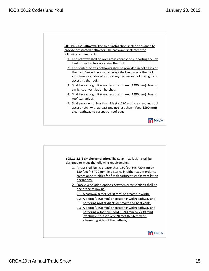
605.11.3.3.2 Pathways. The solar installation shall be designed to provide designated pathways. The pathways shall meet the following requirements:
1. The pathway shall be over areas capable of supporting the live load of fire fighters accessing the roofload of fire fighters accessing the roof.
2. The centerline axis pathways shall be provided in both axes of the roof. Centerline axis pathways shall run where the roof structure is capable of supporting the live load of fire fighters accessing the roof.
3. Shall be a straight line not less than 4 feet (1290 mm) clear to skylights or ventilation hatches.
4 Shall be a straight line not less than 4 feet (1290 mm) clear to4. Shall be a straight line not less than 4 feet (1290 mm) clear to roof standpipes.
5. Shall provide not less than 4 feet (1290 mm) clear around roof access hatch with at least one not less than 4 feet (1290 mm) clear pathway to parapet or roof edge.
605.11.3.3.3 Smoke ventilation. The solar installation shall be designed to meet the following requirements:
1. Arrays shall be no greater than 150 feet (45 720 mm) by 150 feet (45 720 mm) in distance in either axis in order to create opportunities for fire department smoke ventilationcreate opportunities for fire department smoke ventilation operations.
2. Smoke ventilation options between array sections shall be one of the following:
2.1 A pathway 8 feet (2438 mm) or greater in width.
2.2 A 4‐foot (1290 mm) or greater in width pathway and bordering roof skylights or smoke and heat vents.
2 3 A 4 f t (1290 ) t i idth th d2.3 A 4‐foot (1290 mm) or greater in width pathway and bordering 4‐foot by 8‐foot (1290 mm by 2438 mm) “venting cutouts” every 20 feet (6096 mm) on alternating sides of the pathway.

ICC’s 2012 Codes and You! January 20, 2012
CRCA 29th Annual Trade Show 16
International Energy Conservation Code,2012 Edition (IECC 2012)
FormatInternational Energy Conservation Code, 2012 Edition
Ch. 1: Administration
Part 1: Scope and Application
Part 2: Administration and Enforcement
Ch. 2: Definitions
Ch. 3: General Requirements
Ch. 4: Commercial Energy Efficiency
Ch. 5: Reference Standards

ICC’s 2012 Codes and You! January 20, 2012
CRCA 29th Annual Trade Show 17
Climate zonesIECC 2012, Section C301—Climate Zones
Compliance pathsIECC 2012, Section C401‐‐General
C401.2 Application. Commercial buildings shall comply with one of the following:
1 The requirements of ANSI/ASHRAE/IESNA 90 11. The requirements of ANSI/ASHRAE/IESNA 90.1.
2. The requirements of Sections C402, C403, C404 and C405. In addition, commercial buildings shall comply with either Section C406.2, C406.3 or C406.4.
3. The requirements of Section C407, C402.4, C403.2, C404, C405.2, C405.3, C405.4, C405.6 and C405.7. The building energy cost shall be equal to or less than 85 percent of the standard reference design buildingbuilding.
C401.2.1 Application to existing buildings. Additions, alterations and repairs to existing buildings shall comply with one of the following:
1. Sections C402, C403, C404 and C405; or
2. ANSI/ASHRAE/IESNA 90.1.

ICC’s 2012 Codes and You! January 20, 2012
CRCA 29th Annual Trade Show 18
Ch. 4—Commercial Energy EfficiencyInternational Energy Efficiency Code, 2012 Edition
• Sec. C402—Building Envelope Requirements
• Sec. C403—Building Mechanical Systems
• Sec. C404—Service Water Heating
• Sec. C405—Electrical Power and Lighting Systems
• Sec C406 Additional Efficiency package Options• Sec. C406—Additional Efficiency package Options
• Sec. C407—Total Building Performance
Minimum thermal insulation requirementsIECC 2009, Section C402.2—Specific insulation Requirements (Prescriptive)
C402.2 Specific insulation requirements (Prescriptive). Opaque assemblies shall comply with Table C402.2. Where two or more layers of continuous insulation board are used in a construction assembly, the continuous insulation boards shall be installed in accordance with Section C303.2. If the continuous insulation board manufacturer’s installation instructions do not address i t ll ti f t l th d j i t b t hinstallation of two or more layers, the edge joints between each layer of continuous insulation boards shall be staggered.
ICC’s 2012 Codes and You! January 20, 2012
CRCA 29th Annual Trade Show 19
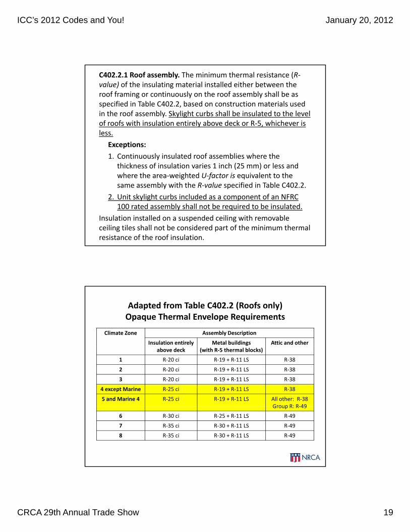
C402.2.1 Roof assembly. The minimum thermal resistance (R‐value) of the insulating material installed either between the roof framing or continuously on the roof assembly shall be as specified in Table C402.2, based on construction materials used in the roof assembly. Skylight curbs shall be insulated to the level of roofs with insulation entirely above deck or R‐5, whichever isof roofs with insulation entirely above deck or R 5, whichever is less.
Exceptions:
1. Continuously insulated roof assemblies where the thickness of insulation varies 1 inch (25 mm) or less and where the area‐weighted U‐factor is equivalent to the same assembly with the R‐value specified in Table C402 2same assembly with the R‐value specified in Table C402.2.
2. Unit skylight curbs included as a component of an NFRC 100 rated assembly shall not be required to be insulated.
Insulation installed on a suspended ceiling with removable ceiling tiles shall not be considered part of the minimum thermal resistance of the roof insulation.
Adapted from Table C402.2 (Roofs only)Opaque Thermal Envelope Requirements
Climate Zone Assembly Description
Insulation entirely Metal buildings Attic and otherabove deck (with R‐5 thermal blocks)
1 R‐20 ci R‐19 + R‐11 LS R‐38
2 R‐20 ci R‐19 + R‐11 LS R‐38
3 R‐20 ci R‐19 + R‐11 LS R‐38
4 except Marine R‐25 ci R‐19 + R‐11 LS R‐38
5 and Marine 4 R‐25 ci R‐19 + R‐11 LS All other: R‐38Group R: R‐49Group R: R‐49
6 R‐30 ci R‐25 + R‐11 LS R‐49
7 R‐35 ci R‐30 + R‐11 LS R‐49
8 R‐35 ci R‐30 + R‐11 LS R‐49

ICC’s 2012 Codes and You! January 20, 2012
CRCA 29th Annual Trade Show 20
How does the Code handletapered insulation systems?
C402.2.1 Roof assembly. The minimum thermal resistance (R‐value) of the insulating material installed either between the roof framing or continuously on the roof assembly shall be as specified in Table C402.2, based on construction materials used in the roof assembly. Skylight curbs shall be insulated to the level of roofs with insulation entirely above deck or R‐5, whichever is less.
Exceptions:
1. Continuously insulated roof assemblies where the thickness of insulation varies 1 inch (25 mm) or less and where the area‐weighted U‐factor is equivalent to the same assembly with the R‐value specified in Table C402.2….
IECC 2009 Commentary indicates Exception 1 language can be applied to tapered roof insulation systems.
Graphically depicted…
ICC’s 2012 Codes and You! January 20, 2012
CRCA 29th Annual Trade Show 21
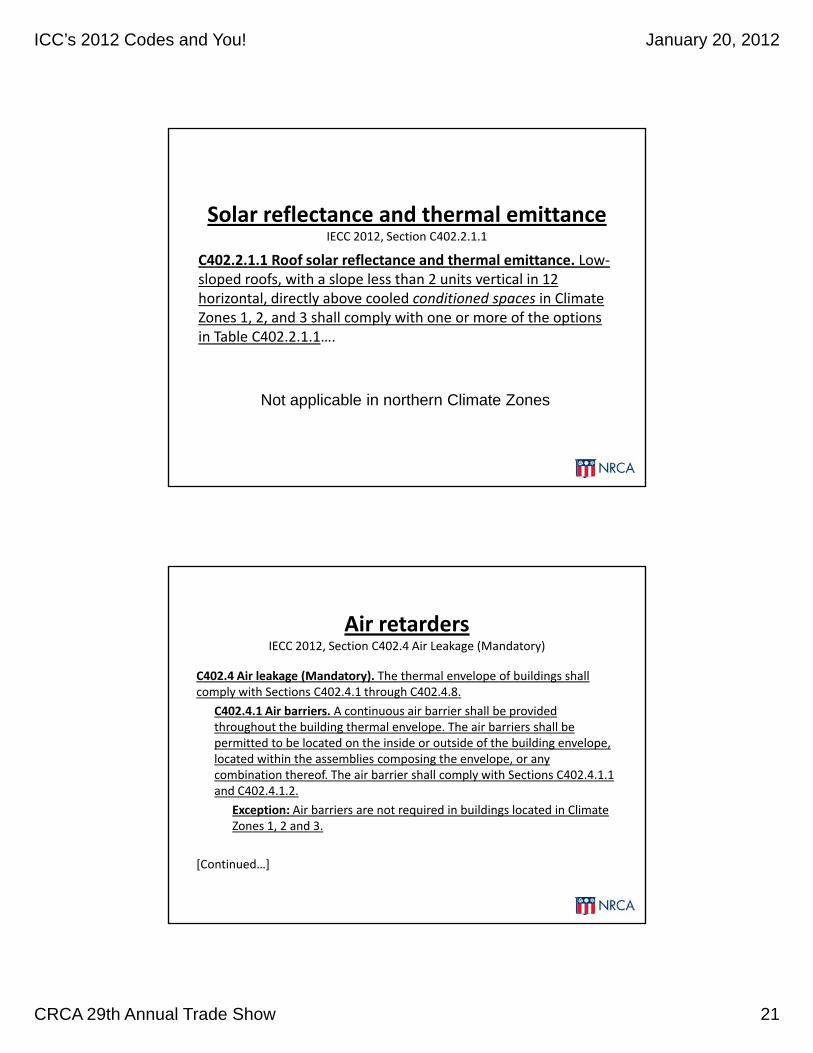
Solar reflectance and thermal emittanceIECC 2012, Section C402.2.1.1
C402.2.1.1 Roof solar reflectance and thermal emittance. Low‐sloped roofs, with a slope less than 2 units vertical in 12 horizontal, directly above cooled conditioned spaces in Climate Zones 1, 2, and 3 shall comply with one or more of the options in Table C402.2.1.1….
Not applicable in northern Climate Zones
Air retardersIECC 2012, Section C402.4 Air Leakage (Mandatory)
C402.4 Air leakage (Mandatory). The thermal envelope of buildings shall comply with Sections C402.4.1 through C402.4.8.
C402.4.1 Air barriers. A continuous air barrier shall be provided throughout the building thermal envelope. The air barriers shall be permitted to be located on the inside or outside of the building envelope, located within the assemblies composing the envelope, or any combination thereof. The air barrier shall comply with Sections C402.4.1.1 and C402.4.1.2.
Exception: Air barriers are not required in buildings located in Climate Zones 1, 2 and 3.
[Continued…]

ICC’s 2012 Codes and You! January 20, 2012
CRCA 29th Annual Trade Show 22
C402.4.1.1 Air barrier construction. The continuous air barrier shall be constructed to comply with the following:
1. The air barrier shall be continuous for all assemblies that are the thermal envelope of the building and across the joints and assemblies.
2. Air barrier joints and seams shall be sealed, including sealing transitions in places and changes in materials. Air barrier penetrations shall be sealed in accordance with Section C402.4.2. The joints and seals shall be securely installed in or on the joint for its entire length so as not to dislodge, loosen or otherwise impair its ability to resist positive and negative pressure from wind, stack effect and mechanical ventilation.
3. Recessed lighting fixtures shall comply with Section C404.2.8. Where similar objects are installed which penetrate the air barrierWhere similar objects are installed which penetrate the air barrier, provisions shall be made to maintain the integrity of the air barrier.
Exception: Buildings that comply with Section C402.4.1.2.3 are not required to comply with Items 1 and 3.
[Continued…]
C402.4.1.2 Air barrier compliance options. A continuous air barrier for the opaque building envelope shall comply with Section C402.4.1.2.1, C402.4.1.2.2, or C402.4.1.2.3.
C402.4.1.2.1 Materials. Materials with an air permeability no greater than 0.004 cfm/ft2 (0.02 L/s ∙ m2) under a pressure differential of 0.3 inches water gauge (w.g.) (75 Pa) when tested in accordance with ASTM E 2178 shall comply with this section Materials in Items 1ASTM E 2178 shall comply with this section. Materials in Items 1 through 15 shall be deemed to comply with this section provided joints are sealed and materials are installed as air barriers in accordance with the manufacturer’s instructions.
1. Plywood with a thickness of not less than 3/8 inch (10 mm).
2. Oriented strand board having a thickness of not less than 3/8 inch (10 mm).
3 Extruded polystyrene insulation board having a thickness of not less3. Extruded polystyrene insulation board having a thickness of not less than 1/2 inch (12 mm).
4. Foil‐back polyisocyanurate insulation board having a thickness of not less than 1/2 inch (12 mm).
5. Closed cell spray foam a minimum density of 1.5 pcf (2.4 kg/m3) having a thickness of not less than 1‐1/2 inches (36 mm).
[Continued….]

ICC’s 2012 Codes and You! January 20, 2012
CRCA 29th Annual Trade Show 23
6. Open cell spray foam with a density between 0.4 and 1.5 pcf (0.6 and 2.4 kg/m3) and having a thickness of not less than 4.5 inches (113 mm).
7. Exterior or interior gypsum board having a thickness of not less than ½ inch (12 mm).
8. Cement board having a thickness of not less than 1/2 inch (12 mm).
9. Built up roofing membrane.
10.Modified bituminous roof membrane.
11.Fully adhered single‐ply roof membrane.
12.A Portland cement/sand parge, or gypsum plaster having a thickness of not less than 5/8 inch (16 mm).
13 Cast in place and precast concrete13.Cast‐in‐place and precast concrete.
14.Fully grouted concrete block masonry.
15.Sheet steel or aluminum.
[Continued…]
C402.4.1.2.2 Assemblies. Assemblies of materials and components with an average air leakage not to exceed 0.04 cfm/ft2 (0.2 L/s ∙ m2) under a pressure differential of 0.3 inches of water gauge (w.g.)(75 Pa) when tested in accordance with ASTM E 2357, ASTM E 1677 or ASTM E 283 shall comply with this section. Assemblies listed in Items 1 and 2 shall be deemed to comply provided joints are sealed andshall be deemed to comply provided joints are sealed and requirements of Section C402.4.1.1 are met.
1. Concrete masonry walls coated with one application either of block filler and two applications of a paint or sealer coating;
2. A Portland cement/sand parge, stucco or plaster minimum 1/2 inch (12 mm) in thickness.
C402.4.1.2.3 Building test. The completed building shall be tested and the air leakage rate of the building envelope shall not exceed 0 40the air leakage rate of the building envelope shall not exceed 0.40 cfm/ft2 at a pressure differential of 0.3 inches water gauge (2.0 L/s ∙ m2
at 75 Pa) in accordance with ASTM E 779 or an equivalent method approved by the code official.
[Continued…]

ICC’s 2012 Codes and You! January 20, 2012
CRCA 29th Annual Trade Show 24
C402.4.2 Air barrier penetrations. Penetrations of the air barrier and paths of air leakage shall be caulked, gasketed or otherwise sealed in a manner compatible with the construction materials and location. Joints and seals shall be sealed in the same manner or taped or covered with a moisture vapor‐permeable wrapping material. Sealing materials shall be appropriate to the construction materials being sealed. The joints and seals shall be securely installed in or on the joint for its entire length so as not to dislodge, loosen or otherwise impair its ability to resist positive and negative pressure from wind stack effect and mechanical ventilationnegative pressure from wind, stack effect and mechanical ventilation.
International Green Construction Code,2012 Edition (IgCC 2012)
ICC’s 2012 Codes and You! January 20, 2012
CRCA 29th Annual Trade Show 25
IgCC 2012IgCC 2012
• Scheduled to be published in March 2012.
• “Overlay code”
• Sustainability of the built environment
Roofing specificInternational Green Construction Code, 2012 Edition
• Material procurement requirements:
“Indigenous” materials– Indigenous materials
• Recycling requirements
• Increased R‐values
• Heat island requirements
• VOC limits• VOC limits
• Requirements for vegetative roofs
• Reroofing (IECC 2012 R‐values)
ICC’s 2012 Codes and You! January 20, 2012
CRCA 29th Annual Trade Show 26
Adoption is somewhat uncertain in Illinois.
Summary
• IBC 2012 relatively minor changes
• IFC 2012 new requirements
• IECC 2012:
– R‐value increases
– Roof reflectivity requirements (not in IL)
– Air barriers
• IgCC 2012 publication and adoption (?)

ICC’s 2012 Codes and You! January 20, 2012
CRCA 29th Annual Trade Show 27
Questions?
Mark S. GrahamMark S. GrahamAssociate Executive Director, Technical Services
National Roofing Contractors Association10255 West Higgins Road, 600Rosemont, Illinois 60018‐5607
(847) 299‐90701‐800‐323‐9545(847) 299‐1183
54
Twitter: www.twitter.com/MarkGrahamNRCA

![[MAG] January 2012](https://img.pdfslide.tips/doc/110x75/568c3b451a28ab0235a983d9/mag-january-2012.jpg)