Embed Size (px)
Citation preview
1
Ichinotsubo, Lene K
From: Donn Kakuda <[email protected]>Sent: Monday, August 13, 2018 9:23 AMTo: Kihara, KevinCc: Lyle Tabata; Ichinotsubo, Lene KSubject: RE: Kekaha Permit UpdateAttachments: SectionIII_ Leachate Plan Rev 8-3-18_Final.pdf
Kevin, Waste Management provided a updated Leachate for your use. Thank you, Donn Kakuda Civil Engineer VI Department of Public Works – Waste Water Division and Solid Waste Division 4444 Rice Street, Suite 500 Lihue, Hawaii 96766 Phone – (808) 241‐4084 or 241‐4836 Fax – (808) 241‐6589
From: Kihara, Kevin <[email protected]> Sent: Wednesday, August 01, 2018 3:21 PM To: Donn Kakuda <[email protected]> Cc: Lyle Tabata <[email protected]>; Ichinotsubo, Lene K <[email protected]>; Alder, Tina <[email protected]>; Apodaca, Travis <[email protected]> Subject: RE: Kekaha Permit Update Donn, Travis, Tina and I discussed using the top of each well as a reference point, and the remaining elevations would be referenced from that point. Using this method requires that tables 4‐1 and 4‐2 be updated, and a discussion on how the elevations were determined should also be provided. Kevin Kihara Hawaii Department of Health Solid and Hazardous Waste Branch Front Desk Phone: (808) 586‐4226 Direct Line: (808) 586‐4244 Fax: (808) 586‐7509 [email protected]
From: Donn Kakuda <[email protected]> Sent: Wednesday, August 01, 2018 11:50 AM To: Kihara, Kevin <[email protected]>
2
Cc: Lyle Tabata <[email protected]>; Ichinotsubo, Lene K <[email protected]> Subject: RE: Kekaha Permit Update Kevin I was talking to all the consultants including Waste Management. So our response to your previous comment is below. We understand you have been in conversation with Travis Apodaca and Tina Adler from Waste Management and that they have answered your comments/questions about the leachate elevations in the three wet wells. Please let me know if you have further questions, or if you would like WM to provide a revised Table 4‐1 and Table 4‐2 from their August 2016 Leachate Management Plan (replace pages 5 and 6). We look forward to receipt of the draft permit. Let me know if you have any other comments. Thank you, Donn Kakuda Civil Engineer VI Department of Public Works – Waste Water Division and Solid Waste Division 4444 Rice Street, Suite 500 Lihue, Hawaii 96766 Phone – (808) 241‐4084 or 241‐4836 Fax – (808) 241‐6589
From: Kihara, Kevin <[email protected]> Sent: Tuesday, July 10, 2018 8:10 AM To: Donn Kakuda <[email protected]> Subject: RE: Kekaha Permit Update Donn, Thanks for the update. I will revise permit to indicate that the compliance elevation will need to be established prior to issuing. Kevin Kihara Hawaii Department of Health Solid and Hazardous Waste Branch Front Desk Phone: (808) 586‐4226 Direct Line: (808) 586‐4244 Fax: (808) 586‐7509 [email protected]
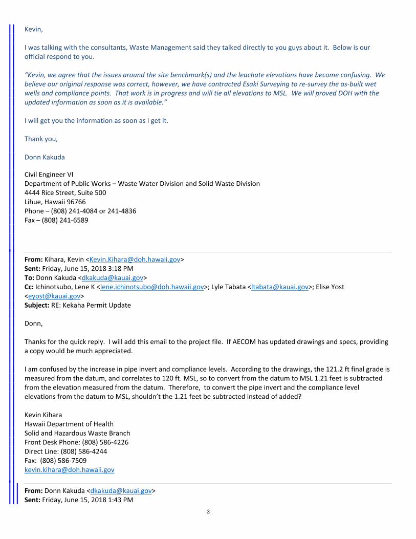
From: Donn Kakuda <[email protected]> Sent: Friday, July 06, 2018 3:08 PM To: Kihara, Kevin <[email protected]> Cc: Ichinotsubo, Lene K <[email protected]>; Lyle Tabata <[email protected]>; Elise Yost <[email protected]> Subject: RE: Kekaha Permit Update
3
Kevin, I was talking with the consultants, Waste Management said they talked directly to you guys about it. Below is our official respond to you. “Kevin, we agree that the issues around the site benchmark(s) and the leachate elevations have become confusing. We believe our original response was correct, however, we have contracted Esaki Surveying to re‐survey the as‐built wet wells and compliance points. That work is in progress and will tie all elevations to MSL. We will proved DOH with the updated information as soon as it is available.” I will get you the information as soon as I get it. Thank you, Donn Kakuda
Civil Engineer VI Department of Public Works – Waste Water Division and Solid Waste Division 4444 Rice Street, Suite 500 Lihue, Hawaii 96766 Phone – (808) 241‐4084 or 241‐4836 Fax – (808) 241‐6589
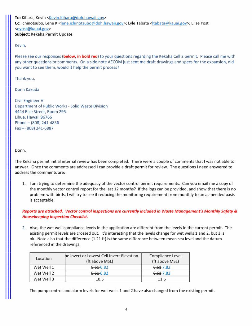
From: Kihara, Kevin <[email protected]> Sent: Friday, June 15, 2018 3:18 PM To: Donn Kakuda <[email protected]> Cc: Ichinotsubo, Lene K <[email protected]>; Lyle Tabata <[email protected]>; Elise Yost <[email protected]> Subject: RE: Kekaha Permit Update Donn, Thanks for the quick reply. I will add this email to the project file. If AECOM has updated drawings and specs, providing a copy would be much appreciated. I am confused by the increase in pipe invert and compliance levels. According to the drawings, the 121.2 ft final grade is measured from the datum, and correlates to 120 ft. MSL, so to convert from the datum to MSL 1.21 feet is subtracted from the elevation measured from the datum. Therefore, to convert the pipe invert and the compliance level elevations from the datum to MSL, shouldn’t the 1.21 feet be subtracted instead of added? Kevin Kihara Hawaii Department of Health Solid and Hazardous Waste Branch Front Desk Phone: (808) 586‐4226 Direct Line: (808) 586‐4244 Fax: (808) 586‐7509 [email protected]
From: Donn Kakuda <[email protected]> Sent: Friday, June 15, 2018 1:43 PM
4
To: Kihara, Kevin <[email protected]> Cc: Ichinotsubo, Lene K <[email protected]>; Lyle Tabata <[email protected]>; Elise Yost <[email protected]> Subject: Kekaha Permit Update Kevin, Please see our responses (below, in bold red) to your questions regarding the Kekaha Cell 2 permit. Please call me with any other questions or comments. On a side note AECOM just sent me draft drawings and specs for the expansion, did you want to see them, would it help the permit process? Thank you, Donn Kakuda Civil Engineer V Department of Public Works ‐ Solid Waste Division 4444 Rice Street, Room 295 Lihue, Hawaii 96766 Phone – (808) 241‐4836 Fax – (808) 241‐6887 Donn, The Kekaha permit initial internal review has been completed. There were a couple of comments that I was not able to answer. Once the comments are addressed I can provide a draft permit for review. The questions I need answered to address the comments are:
1. I am trying to determine the adequacy of the vector control permit requirements. Can you email me a copy of the monthly vector control report for the last 12 months? If the logs can be provided, and show that there is no problem with birds, I will try to see if reducing the monitoring requirement from monthly to an as‐needed basis is acceptable.
Reports are attached. Vector control inspections are currently included in Waste Management’s Monthly Safety & Housekeeping Inspection Checklist.
2. Also, the wet well compliance levels in the application are different from the levels in the current permit. The
existing permit levels are crossed out. It’s interesting that the levels change for wet wells 1 and 2, but 3 is ok. Note also that the difference (1.21 ft) is the same difference between mean sea level and the datum referenced in the drawings.
Location pe Invert or Lowest Cell Invert Elevation
(ft above MSL) Compliance Level (ft above MSL)
Wet Well 1 5.61 6.82 6.61 7.82
Wet Well 2 5.61 6.82 6.61 7.82
Wet Well 3 10.5 11.5
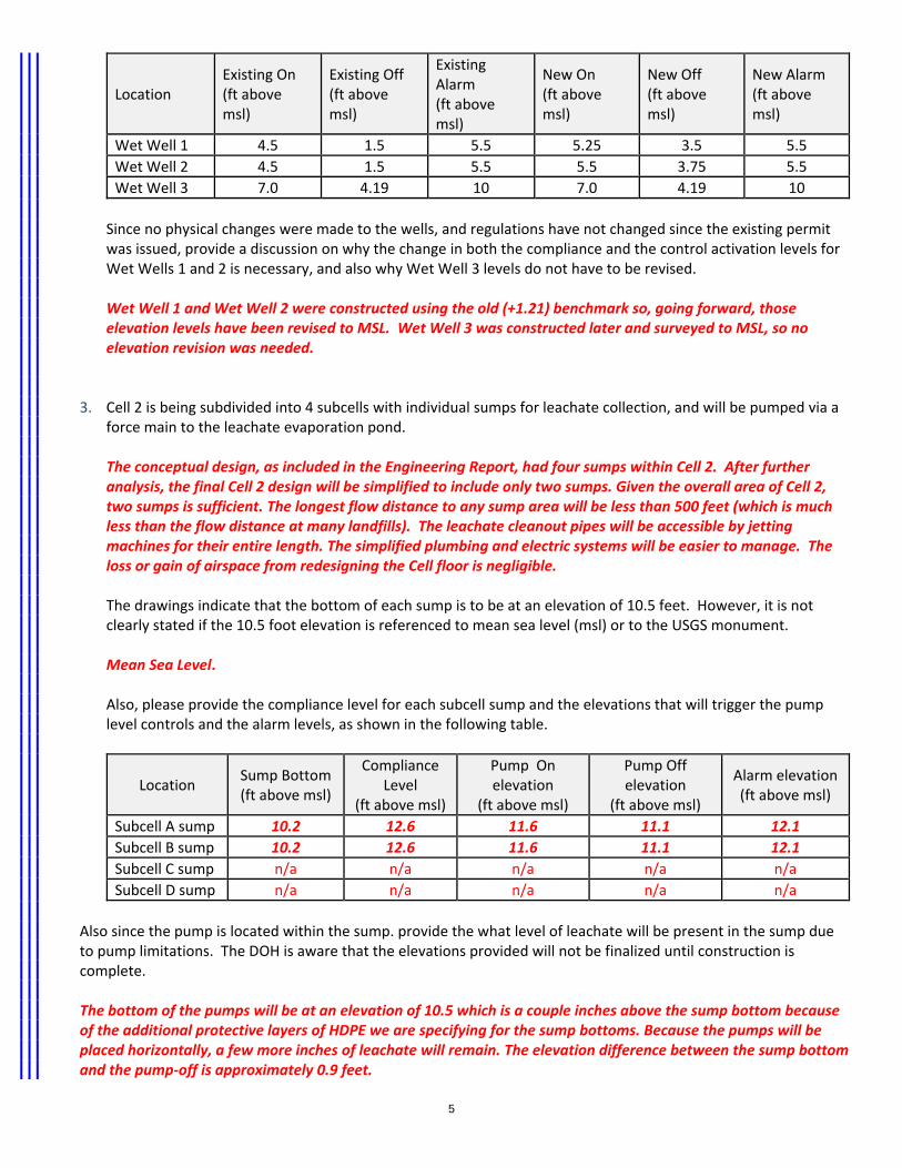
The pump control and alarm levels for wet wells 1 and 2 have also changed from the existing permit.
5
Location Existing On (ft above msl)
Existing Off (ft above msl)
Existing Alarm (ft above msl)
New On (ft above msl)
New Off (ft above msl)
New Alarm (ft above msl)
Wet Well 1 4.5 1.5 5.5 5.25 3.5 5.5
Wet Well 2 4.5 1.5 5.5 5.5 3.75 5.5
Wet Well 3 7.0 4.19 10 7.0 4.19 10
Since no physical changes were made to the wells, and regulations have not changed since the existing permit was issued, provide a discussion on why the change in both the compliance and the control activation levels for Wet Wells 1 and 2 is necessary, and also why Wet Well 3 levels do not have to be revised. Wet Well 1 and Wet Well 2 were constructed using the old (+1.21) benchmark so, going forward, those elevation levels have been revised to MSL. Wet Well 3 was constructed later and surveyed to MSL, so no elevation revision was needed.
3. Cell 2 is being subdivided into 4 subcells with individual sumps for leachate collection, and will be pumped via a
force main to the leachate evaporation pond. The conceptual design, as included in the Engineering Report, had four sumps within Cell 2. After further analysis, the final Cell 2 design will be simplified to include only two sumps. Given the overall area of Cell 2, two sumps is sufficient. The longest flow distance to any sump area will be less than 500 feet (which is much less than the flow distance at many landfills). The leachate cleanout pipes will be accessible by jetting machines for their entire length. The simplified plumbing and electric systems will be easier to manage. The loss or gain of airspace from redesigning the Cell floor is negligible. The drawings indicate that the bottom of each sump is to be at an elevation of 10.5 feet. However, it is not clearly stated if the 10.5 foot elevation is referenced to mean sea level (msl) or to the USGS monument. Mean Sea Level. Also, please provide the compliance level for each subcell sump and the elevations that will trigger the pump level controls and the alarm levels, as shown in the following table.
Location Sump Bottom (ft above msl)
Compliance Level
(ft above msl)
Pump On elevation
(ft above msl)
Pump Off elevation
(ft above msl)
Alarm elevation (ft above msl)
Subcell A sump 10.2 12.6 11.6 11.1 12.1
Subcell B sump 10.2 12.6 11.6 11.1 12.1
Subcell C sump n/a n/a n/a n/a n/a
Subcell D sump n/a n/a n/a n/a n/a
Also since the pump is located within the sump. provide the what level of leachate will be present in the sump due to pump limitations. The DOH is aware that the elevations provided will not be finalized until construction is complete. The bottom of the pumps will be at an elevation of 10.5 which is a couple inches above the sump bottom because of the additional protective layers of HDPE we are specifying for the sump bottoms. Because the pumps will be placed horizontally, a few more inches of leachate will remain. The elevation difference between the sump bottom and the pump‐off is approximately 0.9 feet.
6
Please let me know if you have any questions. FYI, I will be out of the office this afternoon and due to the Kamehameha Day State Holiday will not return until Tuesday.
SECTION III
LEACHATE MANAGEMENT PLAN
LEACHATE MANAGEMENT PLAN
KEKAHA MUNICIPAL SOLID WASTE LANDFILL – PHASE II
KEKAHA, KAUA‘I
PREPARED BY
WASTE MANAGEMENT OF HAWAII, INC.
REVISED AUGUST 2018
i
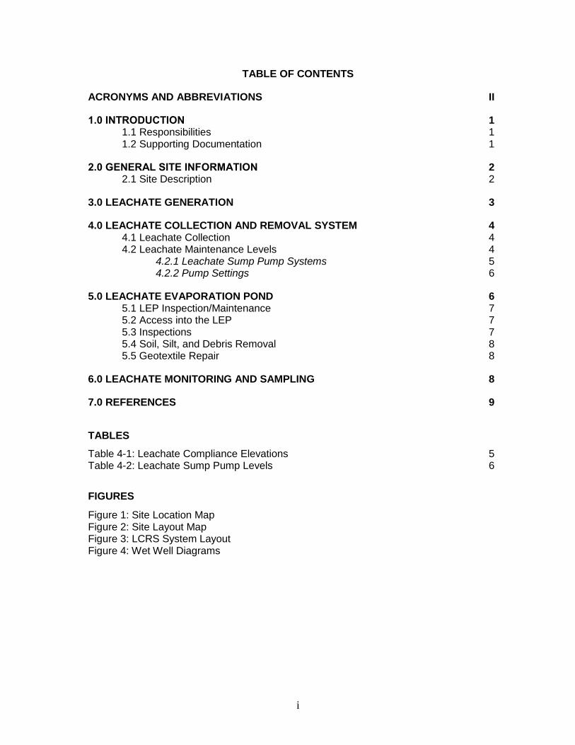
TABLE OF CONTENTS
ACRONYMS AND ABBREVIATIONS II
1.0 INTRODUCTION 1 1.1 Responsibilities 1 1.2 Supporting Documentation 1
2.0 GENERAL SITE INFORMATION 2 2.1 Site Description 2
3.0 LEACHATE GENERATION 3
4.0 LEACHATE COLLECTION AND REMOVAL SYSTEM 4 4.1 Leachate Collection 4 4.2 Leachate Maintenance Levels 4
4.2.1 Leachate Sump Pump Systems 5 4.2.2 Pump Settings 6
5.0 LEACHATE EVAPORATION POND 6 5.1 LEP Inspection/Maintenance 7 5.2 Access into the LEP 7 5.3 Inspections 7 5.4 Soil, Silt, and Debris Removal 8 5.5 Geotextile Repair 8
6.0 LEACHATE MONITORING AND SAMPLING 8
7.0 REFERENCES 9
TABLES
Table 4-1: Leachate Compliance Elevations 5 Table 4-2: Leachate Sump Pump Levels 6
FIGURES
Figure 1: Site Location Map Figure 2: Site Layout Map Figure 3: LCRS System Layout Figure 4: Wet Well Diagrams
ii
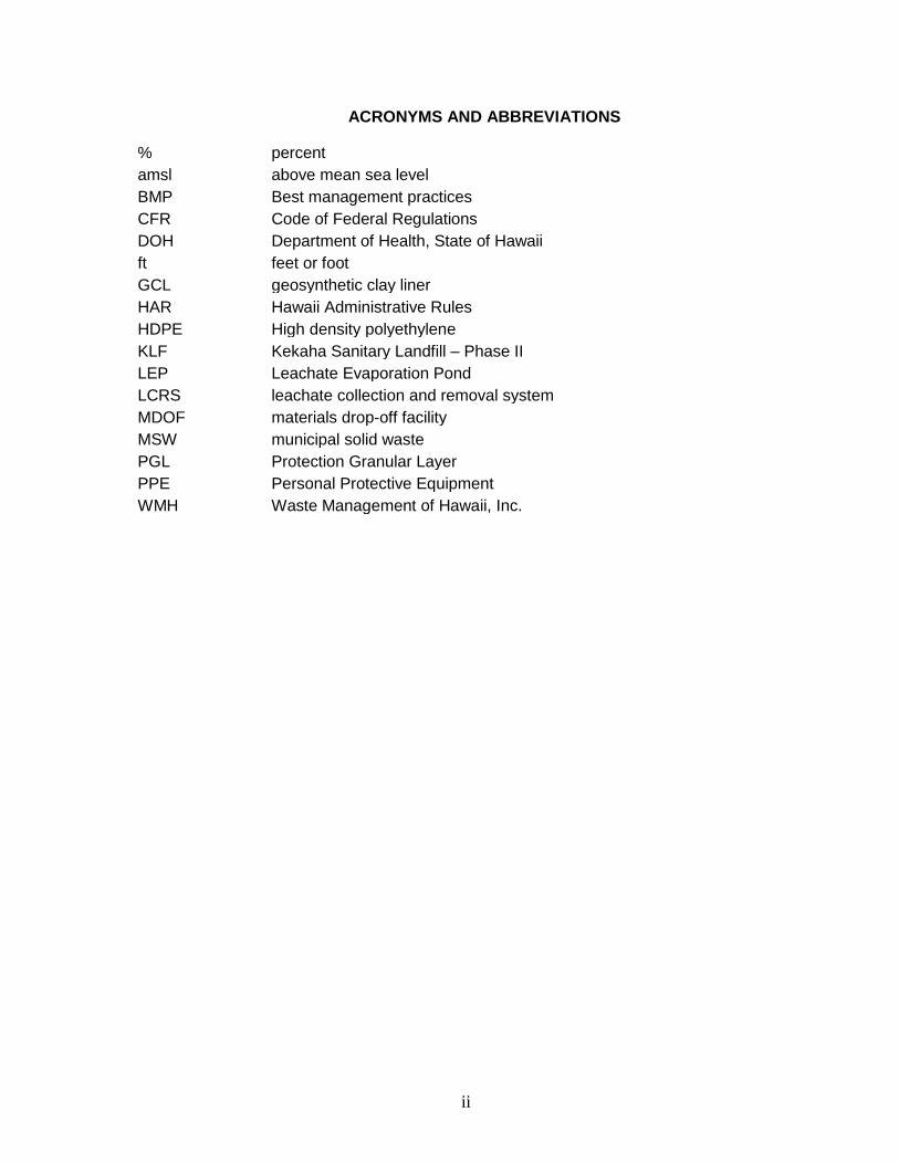
ACRONYMS AND ABBREVIATIONS
% percent amsl above mean sea level BMP Best management practices CFR Code of Federal Regulations DOH Department of Health, State of Hawaii ft feet or foot GCL geosynthetic clay liner HAR Hawaii Administrative Rules HDPE High density polyethylene KLF Kekaha Sanitary Landfill – Phase II LEP Leachate Evaporation Pond LCRS leachate collection and removal system MDOF materials drop-off facility MSW municipal solid waste PGL Protection Granular Layer PPE Personal Protective Equipment WMH Waste Management of Hawaii, Inc.
1
1.0 INTRODUCTION
Waste Management of Hawaii, Inc. (WMH) has prepared this Leachate Management Plan to establish standard operating and maintenance procedures for leachate generated at the Kekaha Sanitary Landfill – Phase II (KLF).
Pursuant to Resource Conservation and Recovery Act Subtitle D regulations 40 Code of Federal Regulations (CFR) §258.40, and Hawaii Administrative Rules (HAR) Title 11, Chapter 58.1 municipal solid waste (MSW) landfills are to be constructed:
• §258.40 (a)(2) “With a composite liner and a leachate collection system that is
designed and constructed to maintain less than 30-cm depth of leachate over
the liner.”
1.1 Responsibilities
The KLF District Manager has overall responsibility for implementation of this plan and all operational activities related to leachate management. The District Manager supervises and interfaces with outside contractors and treatment facilities, schedules the necessary tanker trucks required to manage leachate, and ensures that observed deficiencies are corrected and documented in a timely manner.
The Waste Management (WM) Environmental Professional works with the District Manager to ensure that leachate levels in the wet wells are maintained and kept in compliance with permit and regulatory requirements. They coordinate the monitoring, sampling, and analytical testing of leachate and ensure that the required reports are submitted to the DOH. The Environmental Protection Manager is the point of contact for regulatory agencies and handles permit compliance issues and notifications to the DOH, as necessary.
1.2 Supporting Documentation
This Leachate Management Plan is part of the KLF Site Operations Manual and should be used as the primary document for leachate management at the facility. There are other documents that support this Plan, which include, but are not limited to the following:
• As-built drawings
• Cell 2 Engineering Report drawings (AECOM 2015)
• Groundwater and Leachate Monitoring Plan
• Leachate pump specifications and operation manual
2
2.0 GENERAL SITE INFORMATION
2.1 Site Description
The KLF is a permitted MSW landfill for the disposal of non-hazardous solid wastes. The KLF property covers an area of approximately 98 acres. The KLF is located near the southwest coast of the island of Kaua`i, approximately 1.5 miles northwest of the town of Kekaha, and approximately 2,000 feet (ft) from the Pacific Ocean shoreline. The KLF is bounded by Kaumuali`i Highway to the northeast, an unpaved access road and agricultural land to the southeast, aquaculture facilities to the northwest, and the KLF Phase I area to the southwest. The KLF is hydraulically upgradient of the KLF Phase I, which is a closed and unlined MSW landfill. No established natural streams or lakes exist within or near the facility. Streams on the inland edge of the coastal plain are diverted to the sugarcane plantation irrigation system (R.M. Towill Corporation 1993). The site location and topography are illustrated on Figure 1.
The current permitted waste footprint, which covers approximately 38.5 acres, is roughly square and includes the Phase II disposal cells and Cell 1 (Figure 2). The permitted waste footprint for Phase II is approximately 32.1 acres and is subdivided into 14 smaller waste disposal cells each about 2 acres (approximately 100 ft wide and 800 ft to 1,100 ft long). The permitted waste footprint for the Cell 1 expansion is approximately 6.4 acres and is subdivided into four (4) smaller waste disposal cells each about one (1) acre (approximately 200 ft wide and 200 ft to 280 ft long).
The Cell 2 expansion of Phase II will increase the landfill horizontally to cover approximately 6.6 acres and is estimated to provide an additional 947,500 cubic yards of gross airspace. The Cell 2 area waste footprint will be divided into two (2) smaller disposal cells. The expanded area will be located between KLF Phase I and Phase II.
The landfill office, scale house, maintenance building, leachate evaporation pond (LEP), and infiltration basin are located along the northeast property line. A materials drop-off facility (MDOF) is located between the LEP and the office. The MDOF provides public drop-offs of green waste, recyclables, MSW, tires and white goods. A used oil drop-off is located in or near the maintenance building. The site layout is shown on Figure 2.
3
3.0 LEACHATE GENERATION
Leachate is generated when water percolates through or purges out of disposed refuse. This percolation can occur when precipitation infiltrates directly into the waste, or when moisture in the refuse (whether present when landfilled or generated after landfilling as a product of bio-decomposition) filters or leaches out. Leachate generation is minimized by using the following best management practices (BMPs):
• Maintaining positive drainage on top of the landfill to minimize infiltration. Runoff from covered areas of the landfill is directed away from the active cells. Precipitation that falls on the active face is managed there and not directed off the landfill.
• Utilize geosynthetic tarps in areas where waste and intermediate soil cover has already been placed. The tarps prevent rainfall and storm water from infiltrating the waste cells, and reduce the potential for erosion.
• Maintain surface water drainage around the perimeter of the landfill to prevent surface water run-on into the active disposal area.
4
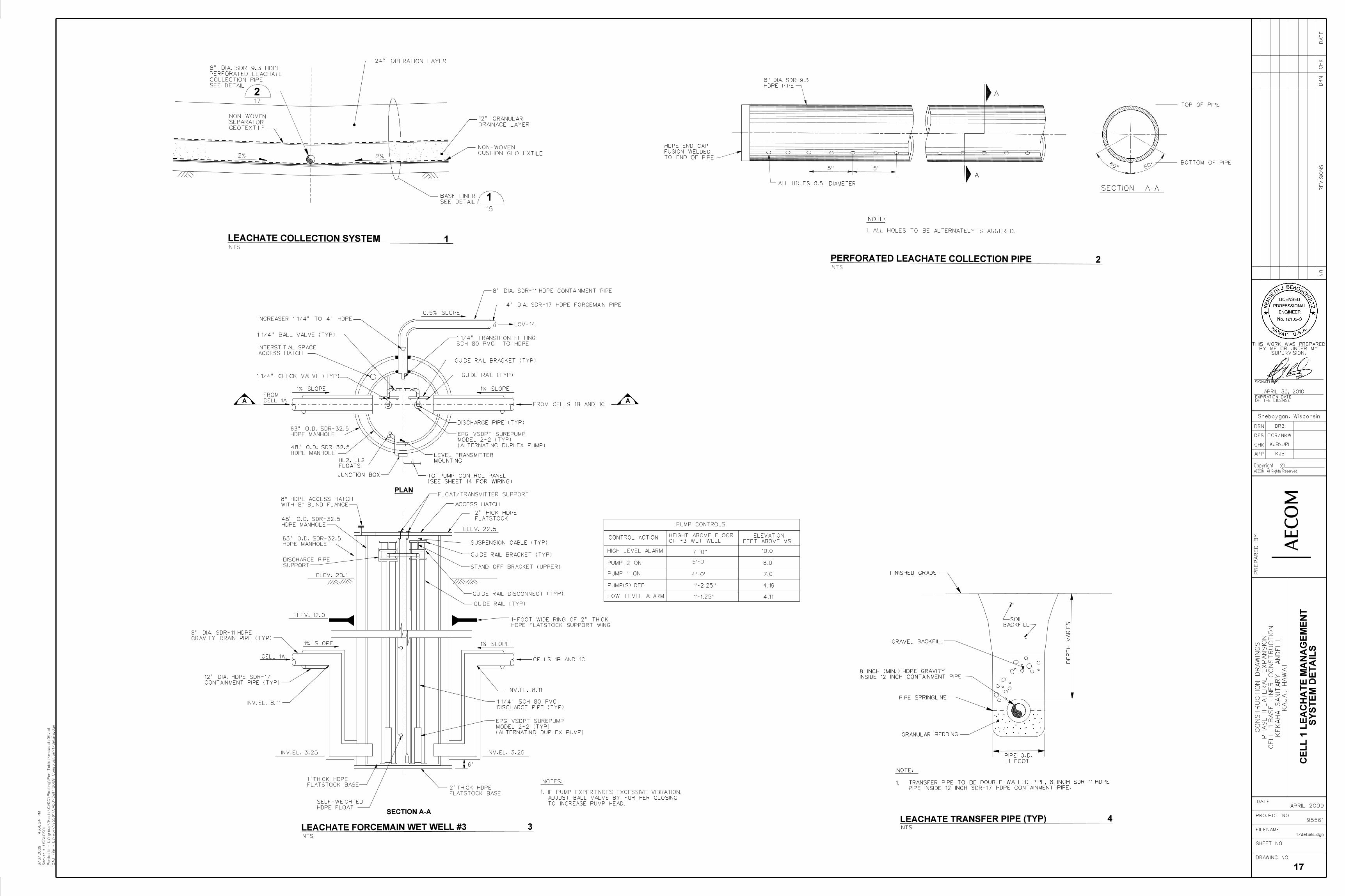
4.0 LEACHATE COLLECTION AND REMOVAL SYSTEM
All disposal areas at KLF are equipped with a bottom and side slope composite liner and leachate collection and removal system (LCRS) meeting Federal (Subtitle D equivalent) and State of Hawaii requirements (HAR 11-58.1-14). A description of the liner systems that are in place at the KLF are detailed in Volume I – Section II (KLF Operations Plan – Section
3.0 Landfill Construction) of this Site Operations Manual
The LCRS consists of a drainage gravel layer on the cell floor, trenches constructed within the liner system (containing drainage gravel & perforated high-density polyethylene [HDPE] pipes), leachate collection manholes, pump stations (e.g. Wet Wells), automatic sump pumps, discharge pipes, pump sensors and controls, and an evaporation pond. The current extraction program in place at the KLF maintains the leachate levels in compliance with federal (Subtitle D) and state regulations, which require that leachate not be allowed to accumulate on the landfill bottom liner to a depth of more than 1-foot, not including leachate contained in the collection sumps. When the leachate level in a wet well reaches a pre-determined height, the pump will automatically start, and pump leachate out of the wet well until the level has dropped to a set height. A force main transfers the leachate from the wet well to the LEP. The LEP occupies 2-acres on the northeast side of the landfill and has a capacity of approximately 3,600,000 gallons.
4.1 Leachate Collection
Phase II was divided into 14 subcells, each graded at a slope of 3 percent (%) toward a central trench for leachate collection. The central trenches are sloped at 0.5% and gravity drain towards two-wet wells (Wet Well-1 and Wet Well-2) which are located outside the lined cell perimeter. Cell 1 consists of three subcells which drain towards central trench that gravity drain to a wet well (Wet Well-3) which is located outside the lined cell perimeter. When the wet wells reach the “pump start” level (set below the compliance elevation), the leachate is pumped through underground pipes to the LEP. Wet Well 3 is pumped to Wet Well 2 which in return is pumped to the LEP.
The proposed Cell 2 LCRS will be constructed in a similar manner to Cell 1; however, the central drains in each of the two subcells will drain towards a sump, rather than a wet well, located within the limits-of-waste in each subcell. Leachate in each sump will be pumped through a side slope riser pipe into a double-contained HDPE force main, which flows to Wet Well 3. The major components of the KLF LCRS are shown on Figure 3.
4.2 Leachate Maintenance Levels
The KLF actively extracts leachate from the collection system. The current extraction program at the KLF maintains the site’s leachate levels in compliance (below the maximum
allowable levels) with federal and state regulations, which require that leachate not accumulate on the landfill bottom liner to a depth of more than 1 ft, not including that contained in the wet wells. Since the leachate is gravity drained to the Wet Wells the
5
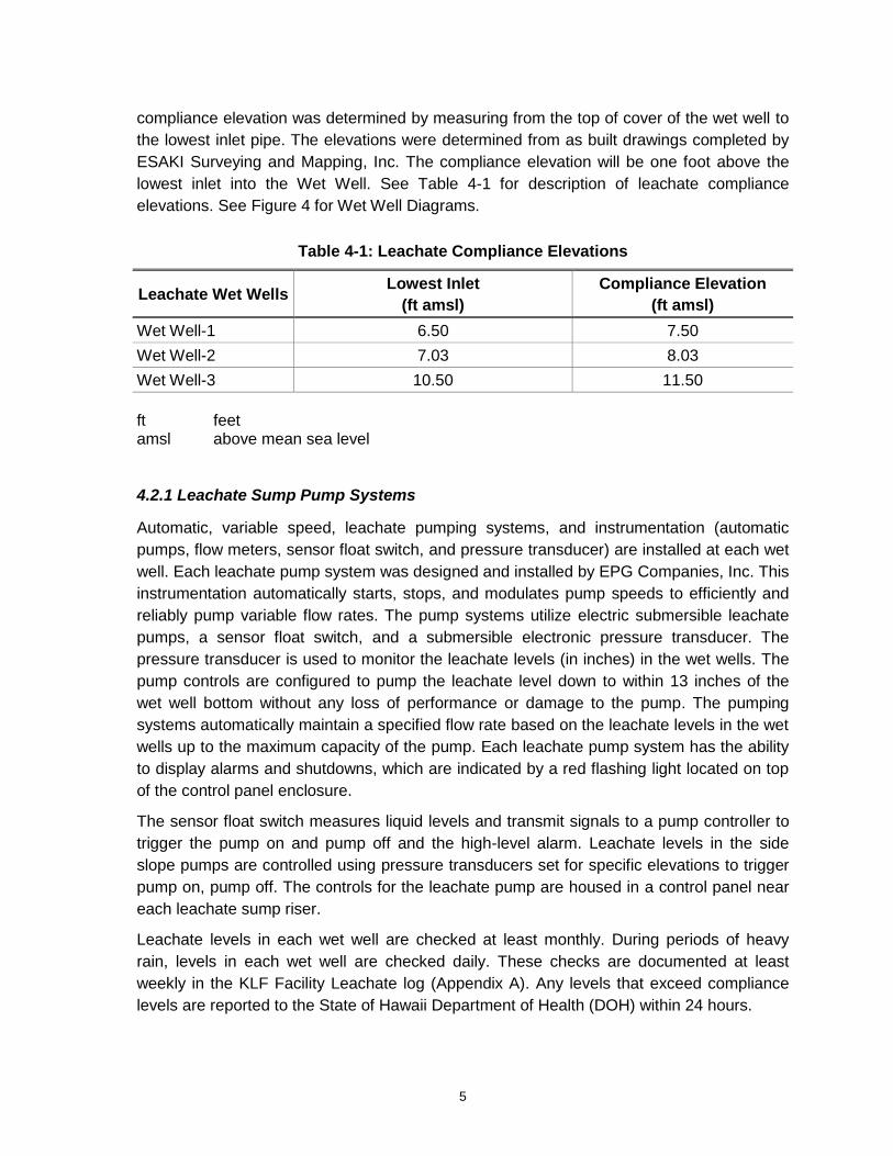
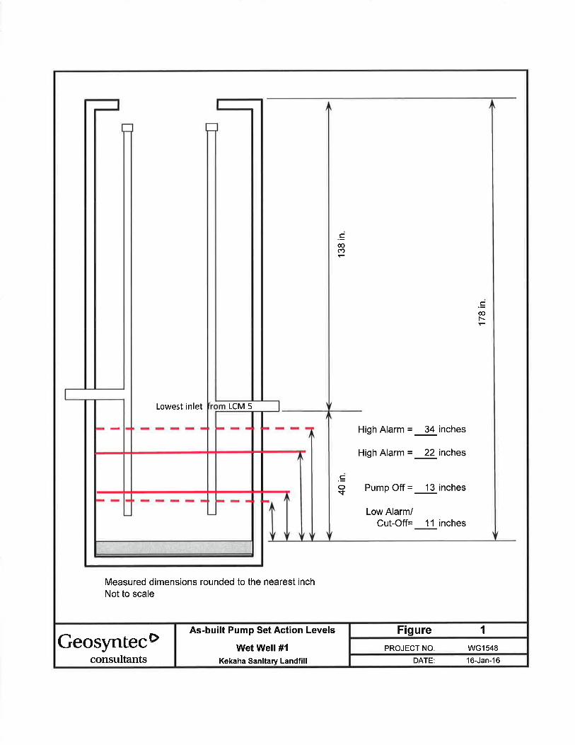
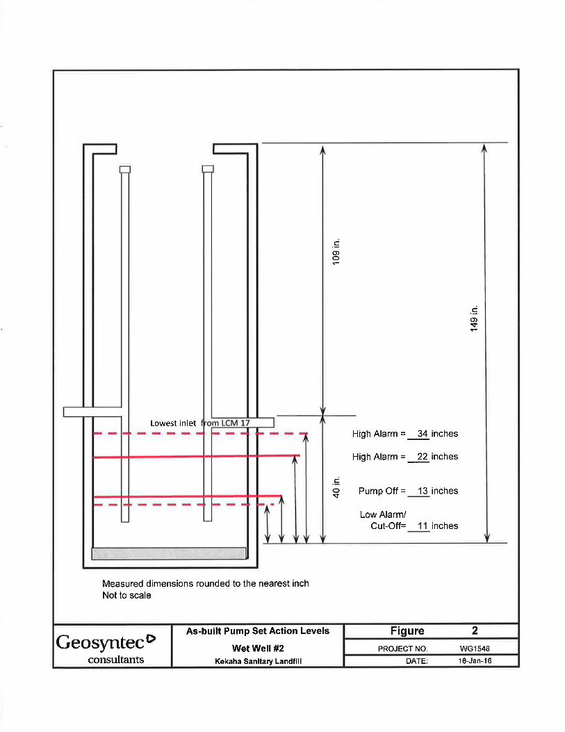
compliance elevation was determined by measuring from the top of cover of the wet well to the lowest inlet pipe. The elevations were determined from as built drawings completed by ESAKI Surveying and Mapping, Inc. The compliance elevation will be one foot above the lowest inlet into the Wet Well. See Table 4-1 for description of leachate compliance elevations. See Figure 4 for Wet Well Diagrams.
Table 4-1: Leachate Compliance Elevations
Leachate Wet Wells Lowest Inlet
(ft amsl)
Compliance Elevation
(ft amsl)
Wet Well-1 6.50 7.50
Wet Well-2 7.03 8.03
Wet Well-3 10.50 11.50 ft feet amsl above mean sea level
4.2.1 Leachate Sump Pump Systems
Automatic, variable speed, leachate pumping systems, and instrumentation (automatic pumps, flow meters, sensor float switch, and pressure transducer) are installed at each wet well. Each leachate pump system was designed and installed by EPG Companies, Inc. This instrumentation automatically starts, stops, and modulates pump speeds to efficiently and reliably pump variable flow rates. The pump systems utilize electric submersible leachate pumps, a sensor float switch, and a submersible electronic pressure transducer. The pressure transducer is used to monitor the leachate levels (in inches) in the wet wells. The pump controls are configured to pump the leachate level down to within 13 inches of the wet well bottom without any loss of performance or damage to the pump. The pumping systems automatically maintain a specified flow rate based on the leachate levels in the wet wells up to the maximum capacity of the pump. Each leachate pump system has the ability to display alarms and shutdowns, which are indicated by a red flashing light located on top of the control panel enclosure.
The sensor float switch measures liquid levels and transmit signals to a pump controller to trigger the pump on and pump off and the high-level alarm. Leachate levels in the side slope pumps are controlled using pressure transducers set for specific elevations to trigger pump on, pump off. The controls for the leachate pump are housed in a control panel near each leachate sump riser.
Leachate levels in each wet well are checked at least monthly. During periods of heavy rain, levels in each wet well are checked daily. These checks are documented at least weekly in the KLF Facility Leachate log (Appendix A). Any levels that exceed compliance levels are reported to the State of Hawaii Department of Health (DOH) within 24 hours.
6
Repairs and maintenance activities that need to be performed on the LCRS or associated equipment are conducted by either some outside electrical contractor or onsite personnel.
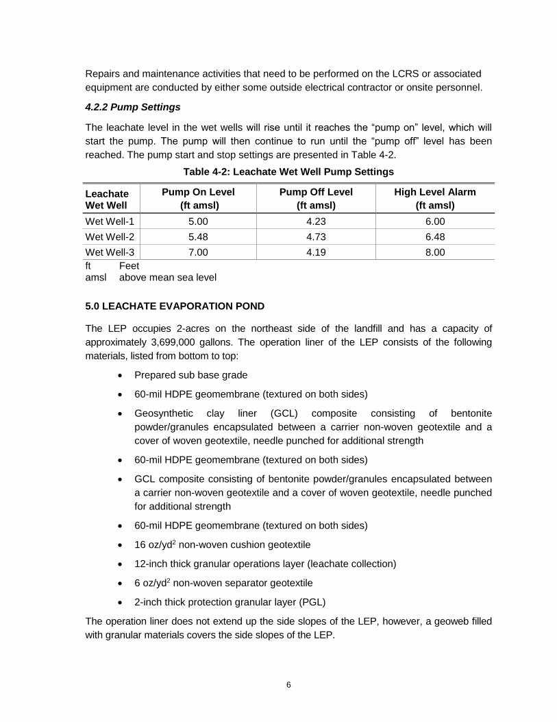
4.2.2 Pump Settings
The leachate level in the wet wells will rise until it reaches the “pump on” level, which will
start the pump. The pump will then continue to run until the “pump off” level has been reached. The pump start and stop settings are presented in Table 4-2.
Table 4-2: Leachate Wet Well Pump Settings
Leachate Wet Well
Pump On Level
(ft amsl)
Pump Off Level
(ft amsl)
High Level Alarm
(ft amsl)
Wet Well-1 5.00 4.23 6.00
Wet Well-2 5.48 4.73 6.48
Wet Well-3 7.00 4.19 8.00 ft Feet amsl above mean sea level
5.0 LEACHATE EVAPORATION POND
The LEP occupies 2-acres on the northeast side of the landfill and has a capacity of approximately 3,699,000 gallons. The operation liner of the LEP consists of the following materials, listed from bottom to top:
• Prepared sub base grade
• 60-mil HDPE geomembrane (textured on both sides)
• Geosynthetic clay liner (GCL) composite consisting of bentonite powder/granules encapsulated between a carrier non-woven geotextile and a cover of woven geotextile, needle punched for additional strength
• 60-mil HDPE geomembrane (textured on both sides)
• GCL composite consisting of bentonite powder/granules encapsulated between a carrier non-woven geotextile and a cover of woven geotextile, needle punched for additional strength
• 60-mil HDPE geomembrane (textured on both sides)
• 16 oz/yd2 non-woven cushion geotextile
• 12-inch thick granular operations layer (leachate collection)
• 6 oz/yd2 non-woven separator geotextile
• 2-inch thick protection granular layer (PGL)
The operation liner does not extend up the side slopes of the LEP, however, a geoweb filled with granular materials covers the side slopes of the LEP.
7
The KLF maintains a log of the status of the LCRS, at least once per week. The log includes the date and volume of leachate pumped into the LEP. Leachate volumes are measured by a flowmeter installed in the leachate pond inlet line. When the flowmeter is not operational, volumetric measurements are calculated based on the size of the wet well and the depth of leachate in the wet well before and after pumping.
5.1 LEP Inspection/Maintenance
All activities associated with the LEP should be completed in accordance with the site-specific health and safety plan or any specific project health and safety plan for work associated near and with the LEP. This includes all monitoring, permits, and personal protective equipment (PPE).
5.2 Access into the LEP
Access into the LEP should be primarily by foot. For safety purposes and whenever possible, the ingress into the LEP should occur when liquid levels are below the top of the PGL and from one of the four LEP corners. Slopes are gentler in the corners than the side slopes. If entrance to the LEP is required with a visible liquid level, activities should be coordinated with the site safety officer before commencing work.
If access is required for light duty equipment, such as a rubber tracked skid steer, the equipment should be lifted/lowered into place by an excavator or similar piece of equipment to avoid vehicle traffic on the LEP sidewalls. No equipment will be operated on the LEP side slopes only along the base. Equipment should avoid quick and tight turns over the indicator geotextile located directly over the PGL. Access for equipment proposed for any maintenance and repair activities will be coordinated with the design engineer.
5.3 Inspections
Inspections of the LEP will be conducted quarterly to identify damaged components, erosion, and other malfunctions that could prevent proper functioning of the LEP. Components to be inspected include the following:
• Force main outlet and metering system
• Side slope geo-cell system/granular fill
• 2-inch granular protection layer
• Observational geotextile layer (non-woven geotextile separating the protection granular layer and the granular operations layer)
Components that are not regularly accessible (e.g., 2-inch thick PGL, and the observational geotextile layer) due to site conditions or because of other maintenance activities may be inspected at reduced intervals. Appropriate repair and maintenance options will be evaluated and maintenance activities performed as necessary.
8
The leachate level in the evaporation pond will be checked at least weekly and after significant environmental events (i.e., large storms, hurricanes, earthquakes, etc.). During periods of heavy rain, levels will be checked at least once per day. The leachate level in the evaporation pond shall not exceed a 6 ft depth, leaving about 2 ft of freeboard.
5.4 Soil, Silt, and Debris Removal
Soil, silt, and debris can potentially collect in the LEP. Soil can collect from wind events and settle in the pond. Silt can enter the LEP through conveyance of leachate to the pond. Debris, such as litter, leaves, or other matter can be blown into the LEP.
For removal of silt and soil on the indicator geotextile, flat shovels and brooms should be used to manually remove material from the geotextile surface. Caution should be taken to avoid damaging the geotextile. If soil is dried and adhering to the geotextile, the soil can be moistened as needed to assist in removal and to avoid damage to the geotextile. Bulk removal of soil can be accomplished through hand buckets, light equipment, or by direct shoveling to an excavator bucket extended from outside the LEP limits.
A final walk over of the indicator geotextile should be performed following soil, silt, and/or debris removal to determine that no damage to the geotextile has occurred and it remains continuous.
5.5 Geotextile Repair
If damage occurs to the indicator geotextile, the type and size of damage and associated repair technique should be documented in site files. For all repairs, a smaller piece of similar geotextile should be sewed to geotextile surrounding the damaged area. If sewing is not available, heat lystering a patch is also acceptable; however, it should be verified that no burn holes or damage to the patch or surrounding geotextile occurred. Repairs should be extended approximately 1 foot past the damage edge.
6.0 LEACHATE MONITORING AND SAMPLING
Leachate is sampled on a semiannual basis at the KLF, in conjunction with the site’s
groundwater monitoring program. KLF groundwater and leachate monitoring activities are conducted pursuant to the KLF Groundwater and Leachate Monitoring Plan (located in Section VI of this Site Operations Manual), which complies with CFR, Solid Waste Disposal Facility Criteria (and its revisions) in 40 CFR Part 258 (Subtitle D) and HAR Title 11, Chapter 58.1.
The KLF Groundwater and Leachate Monitoring Plan (Section IV) describes the leachate monitoring system, including, but not limited to: leachate monitoring locations, monitoring parameters, data evaluation methods, and sampling and analytical procedures.
9
7.0 REFERENCES
AECOM, 2015. Engineering Report Kekaha Sanitary Landfill Phase II, Cell 2 Lateral Expansion, Kekaha, Kaua‘i, Hawai‘i. September.
R. M. Towill Corporation, 1993, Revised Environmental Impact Statement, Kekaha Sanitary Landfill Expansion Project. Report prepared for the County of Kauai, Department of Public Works. December.


FIGURES


Figure 1: Site Location Map

KEKAHA LANDFILL
LOCATION MAP
LEGEND
´0 2,000 4,0001,000
Feet
Figure 1Site Location Map
Kekaha LandfillKauai, Hawaii
Kauai
Kilauea
Kekaha
Lihua
Kapaa
Pacific
Ocean
Site Location
¯0 5 102.5Miles
Roads
NOTES
1. Map projection is Hawaii State Plane,Zone 4, NAD83.
2. Base map: ArcGIS Bring Map Aerial
P:\
EN
V\N
on-F
ed
era
l\C
ou
nty
of K
aua
i\6
01
35
72
2 K
AU
AI-
Ke
ka
ha
Ce
ll 1
\07
De
livera
ble
s\G
IS\0
2_M
XD
\Fig
ure
1 -
Site L
ocatio
n M
ap
.mxd
08/29/201308/29/2013

Figure 2: Site Layout Map

08/29/201308/29/2013

Figure 3: LCRS System Layout

08/29/201308/29/2013

Figure 4: Wet Well Diagrams
RE
VIS
ION
S
CHK
c
APP
DES
DRN
DRAWING NO
SHEET NO
FILENAME
PROJECT NO
DATE
NO
DR
NC
HK
DA
TE
PR
EP
AR
ED
BY
17details.dgn
95561
Server =
US
SH
BS
01
L:\
work\9
5561\C
AD
D\C
ell
1 2
009 C
onstr
ucti
on\1
7deta
ils.d
gn
6/3
/2
00
94
:01
:24
PM
CA
D F
ile =
L:\
group\W
aste
\CA
DD
\Plo
ttin
g\P
en T
able
s\m
sw
aste
DK
.tbl
Pen
tab
le =
Sheboygan, Wisconsin
DRB
KJB
TCR/NKW
CO
NS
TR
UC
TIO
N D
RA
WIN
GS
PH
AS
E I
I L
AT
ER
AL
EX
PA
NS
ION
CE
LL
1 B
AS
E L
INE
R C
ON
ST
RU
CT
ION
KE
KA
HA
SA
NIT
AR
Y L
AN
DF
ILL
KA
UA
I, H
AW
AII
APRIL 2009
KJB\JPI
CopyrightAECOM All Rights Reserved
THIS WORK WAS PREPAREDBY ME OR UNDER MY
SUPERVISION.
EXPIRATION DATEOF THE LICENSE
APRIL 30, 2010
SIGNATURE
NTS
NTS
NTS
SOIL
BACKFILL
1.
NOTE:
PIPE SPRINGLINE
GRAVEL BACKFILL
..
.
. .
.
.
.
..
.
.. ...
.
... ..
.
...
..
.
GRANULAR BEDDING
FINISHED GRADE
. . ..
NTS
A
SECTION A-AALL HOLES 0.5" DIAMETER
A
NOTE:
1. ALL HOLES TO BE ALTERNATELY STAGGERED.
60^ 60^
TOP OF PIPE
BOTTOM OF PIPE
17
CE
LL
1 L
EA
CH
AT
E M
AN
AG
EM
EN
T
SY
ST
EM
DE
TA
ILS
LEACHATE COLLECTION SYSTEM 1
12" GRANULAR
DRAINAGE LAYER
17
2
24" OPERATION LAYER
8" DIA. SDR-9.3 HDPE
PERFORATED LEACHATE
COLLECTION PIPE
SEE DETAIL
PERFORATED LEACHATE COLLECTION PIPE 2
NON-WOVEN
SEPARATOR
GEOTEXTILE
NON-WOVEN
CUSHION GEOTEXTILE
115
BASE LINER
SEE DETAIL
PIPE O.D.
+1-FOOT
LEACHATE TRANSFER PIPE (TYP) 4
DE
PT
H V
AR
IES
2% 2%
SECTION A-A
LEACHATE FORCEMAIN WET WELL #3 3
ACCESS HATCH
2"THICK HDPE
FLATSTOCK
1% SLOPE
INV.EL. 8.11
CELLS 1B AND 1C
2"THICK HDPE
FLATSTOCK BASE
5" 5"
1"THICK HDPE
FLATSTOCK BASE
INV.EL. 8.11
1% SLOPE
CELL 1A
INV.EL. 3.25INV.EL. 3.25
6"
GUIDE RAIL (TYP)
STAND OFF BRACKET (UPPER)
DISCHARGE PIPE
SUPPORT
SUSPENSION CABLE (TYP)
GUIDE RAIL BRACKET (TYP)
GUIDE RAIL DISCONNECT (TYP)
1% SLOPE1% SLOPE
DISCHARGE PIPE (TYP)
GUIDE RAIL (TYP)
GUIDE RAIL BRACKET (TYP)
PLAN
8" DIA. SDR-9.3
HDPE PIPE
HDPE END CAP
FUSION WELDED
TO END OF PIPE
LCM-14
ELEV. 22.5
ELEV. 20.1
8" HDPE ACCESS HATCH
WITH 8" BLIND FLANGE
1 1/4" SCH 80 PVC
DISCHARGE PIPE (TYP)
INTERSTITIAL SPACE
ACCESS HATCH
1 1/4" CHECK VALVE (TYP)
8 INCH (MIN.) HDPE GRAVITY
INSIDE 12 INCH CONTAINMENT PIPE
ELEV. 12.0
0.5% SLOPE
1 1/4" TRANSITION FITTING
SCH 80 PVC TO HDPE
FROM
CELL 1AFROM CELLS 1B AND 1C
1 1/4" BALL VALVE (TYP)
INCREASER 1 1/4" TO 4" HDPE
EPG VSDPT SUREPUMP
MODEL 2-2 (TYP)
(ALTERNATING DUPLEX PUMP)
EPG VSDPT SUREPUMP
MODEL 2-2 (TYP)
(ALTERNATING DUPLEX PUMP)
NOTES:
1. IF PUMP EXPERIENCES EXCESSIVE VIBRATION,
ADJUST BALL VALVE BY FURTHER CLOSING
TO INCREASE PUMP HEAD.
1-FOOT WIDE RING OF 2" THICK
HDPE FLATSTOCK SUPPORT WING
CONTROL ACTION
PUMP CONTROLS
HEIGHT ABOVE FLOOR
OF #3 WET WELL
HIGH LEVEL ALARM
PUMP 2 ON
PUMP(S) OFF
LOW LEVEL ALARM
7’-0"
5’-0"
4’-0"
1’-2.25"
1’-1.25"
10.0
8.0
7.0
4.19
4.11
ELEVATION
FEET ABOVE MSL
PUMP 1 ON
TRANSFER PIPE TO BE DOUBLE-WALLED PIPE, 8 INCH SDR-11 HDPE
PIPE INSIDE 12 INCH SDR-17 HDPE CONTAINMENT PIPE.
8" DIA. SDR-11 HDPE CONTAINMENT PIPE
4" DIA. SDR-17 HDPE FORCEMAIN PIPE
63" O.D. SDR-32.5
HDPE MANHOLE
48" O.D. SDR-32.5
HDPE MANHOLE
48" O.D. SDR-32.5
HDPE MANHOLE
63" O.D. SDR-32.5
HDPE MANHOLE
8" DIA. SDR-11 HDPE
GRAVITY DRAIN PIPE (TYP)
12" DIA. HDPE SDR-17
CONTAINMENT PIPE (TYP)
TO PUMP CONTROL PANEL
(SEE SHEET 14 FOR WIRING)
JUNCTION BOX
HL2, LL2
FLOATS
SELF-WEIGHTED
HDPE FLOAT
LEVEL TRANSMITTER
MOUNTING
FLOAT/TRANSMITTER SUPPORT