Embed Size (px)
Citation preview
l
IMPIANTI E APPARECCHIATURE
La camera a ionizzazione a pareti in grafite
dell'Istituto Superiore di Sanità
:'tfAaTA CREliONESE, Lucro PUGLIANI e C.uu.o RIDOLFI (~)
Laborawri di F~ica
Riassunto. - In questo lavoro viene descritta la camera standard a pareti in grafite, disegnata e costruita nei Laboratori di Fisica dell'Istituto Superiore di Sanità. Ne viene descritto il funzionamento e sono riportati i metodi di misura ed i fattori correttivi necessari alla messa a punto della camera rispetto ad una sorgente Ra226 • Viene quindi calcolato il valore della costante specifica di emissione del radio,
Swnmary (The graphite-cavity ionization chamber of the Istituto Supe• riore di Sanità).- A standard cavity chamher with graphite walls, designed and built at the Physics Laboratory of the Istituto Superiore di Sanità, is described. In this work the procedures adopted to carry out a precise measurement with this instrument are reported, together with ali the correcting factors related to its standardization with respect to the Ra220 source. The specific I' -ray constant of the Ra220 has heen determined.
INTRODUZIONE
Presso i Laboratori di Fisica dell'Istituto Superiore di Sanità è stata messa in funzione da vari anni una camera standard a ionizzazione ad aria libera (Mrssom & PUGLIA.Nl, 1966) che rappresenta uno standard primario per le radiazioni elettromagnetiche di energia compresa fra 50 e 300 keV. Con il presente lavoro i Laboratori di Fisica hanno voluto ampliare il campo degli standard primari in dotazione dell'Istituto. È stata quindi messa a punto una camera a ionizzazione a pareti di grafite che permette una
(*) Ospite presso i Laboratori di Fbica.
Arm. ht. s~ver. s,nild (19Hl lo, 7U-94
DIPIANTI E APPA.llECCHIATUR1:
misura della radiazione compresa nell'intervallo di energia 0,3-2 Me V. La messa a punto de1Ia camera standard è stata eseguita rispetto ad una sorgente di Ra220•
DESCRIZIONE DELLA CAMERA E SUE CARATTERISTICH.t"
La camera a ionizzazione è stata eseguita in grafite, materiale che ga· rantisce un'ottima equivalenza fra le pareti della camera e l'aria contenuta nel suo interno. Infatti per il rapporto di poteri frenanti in una camera di piccole dimensioni 0 = 4 cm cui corrispondono i raggi 15 di energ1a E= SO KeV, in base alla teoria di Burlin si ha (BURLIN, 1966):
l dE gm
e dx aria (! = cm3
ms = ~ 0,999 ± 0,002 l dE dE Me V e dx
grafite --~--
dx cm
mentre per il rapporto dei coefficienti massicci di assorbimento (m. a.) è stata eseguita la media pesata
• L P, (m. a.)1 (aria)
m. a. (aria) _ -'''-'-'-''--'(=m";. ;;.•.,),C>(.O:g..::afi='::':!..) 9 --- = 0,99 ± 0,002 m. a. (grafite) P 1
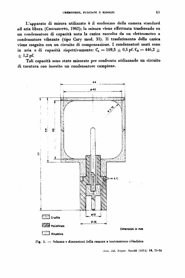
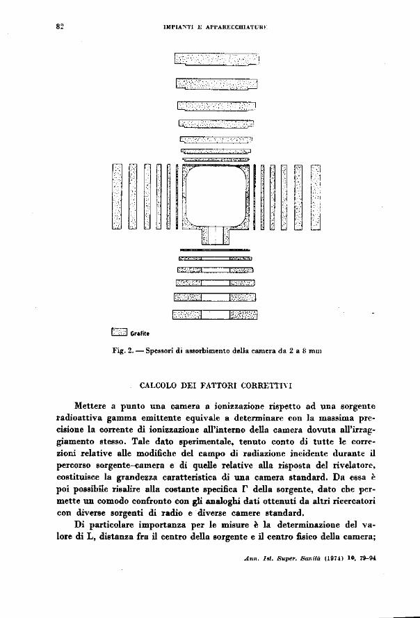
ove i pesi P1 rappresentano il contributo dato alla ionizzazione dalle righe del radio filtrato (A'ITIX et al., 1968, a, b, c). La camera descritta in Fig. l è stata C08truita al tornio ed ha un volume di raccolta di 45,61 ± 0,13 cm3
ed è dotata di 7 spessori di grafite (Fig. 2) in modo da poter funzionare con spessori variabili da 2 a 8 m.m. Durante le misure la parete esterna della ca· mera viene portata ad alta tensione, mentre l'elettrodo collettore interno è mantenuto a potenziale zero. All'interno della camera si ha un campo elettrico radiale; in queste condizioni l'elettrodo collettore raccoglie tutti gli ioni di uno stesso segno generati nel volume gassoso all'interno della camera dagli elettroni compton prodotti dall'interazione fra i gamma emessi dalla sorgente e le pareti in grafite della camera stessa .
.Ann. lat. Supa. San«.i (1974.) 10, 79-9t
4
l
CREliiONESI:, PUGLIANl E RIDOLFI 81
L'apparato di misura utilizzato è il medesimo della camera standard ad aria libera (CHIOZZO'I"l'O, 1962); la misura viene effettuata trasferendo su un condensatore di capacità nota la carica raccolta da un elettrometro a condensatore vibrante (tipo Cary mod. 31). Il trasferimento della carica viene eseguito con un circuito di compensazione. l condensatori usati sono in aria e di capacità rispettivamente: cl = 109,3 ± 0,5 pf. ~ = 446,2 ± ± 1,2 pf.
Tali capacità sono state misurate per confronto utilizzando un circuito di taratura con inserito un condensatore campione .
,, ,, l
---'-:. , __
~ Polistirolo
f:·:-.··1 Alluminio
.. - - _______ ______,
A.T.
Oimensio!li in mrn
Fig. l. ~ Schema e dimensioni della camera a ioni~zazione cilindrica
.11111. I~t. s~per. Sa11itd (1971) lt. 79-94
"
1
O Grafite
IMPIA..,.TI l: AI'I'ARECCDIATl:UI
L.J:C:::_· · .. ·. :::=::l
. ' _._~"l
r i 1\ .J .li.IT
f;·.·: . .-,·,.1
!.-.. ,;-;,::1
l• •·<l
[':•·<J
r:.<- .-.. n
1:-::;;:,: ::J
1,,.,,, ;..;[
flPl
l[.[ l i
i j l :
~lJ
Fig. 2.- Spessori di a!!Sorbimento della camera da 2 a 8 rom
CALCOLO DEI FATTORI CORRETTI\"!
Mettere a punto una camera a ionizzazione rispetto ad una sorgente radioattiva gamma emittente equivale a determinare con la massima precisione la corrente di ionizzazione all'interno della camera dovuta all'irrag:giamento stesso. Tale dato sperimentale, tenuto conto di tutte le corre• zioni relative alle modifiche del campo di radiazione incidente durante il percorso sorgente-camera e di quelle relative alla risposta del rivelatore, costituisce la grandezza caratteristica di una camera standard. Da essa è poi possibile risalire alla costante specifica r della sorgente, dato che perw mette un comodo confronto con gli analoghi dati ottenuti da altri ricercatori con diverse sorgenti di radio e diverse camere standard,
Di particolare importanza per le misure è la determinazione del valore di L, distanza fra il centro della sorgente e il centro fisico della camera;
An". I81. Super. Sa~ità (191-1) IO, 79--94.
i l 1
CREMONESE, PUGLIANI E RIDOLJ!'I " quel punto della camera cioè rispetto al quale è verificata la legge dell'in· verso del quadrato della distanza. La distanza sorgente-camera viene mi· surata con un sistema di due cannocchiali che traguardano un regolo semi· rnillimetrato posto lungo l'asse sorgente-camera; l'errore sulla misura L è contenuto entro 0,5 mm, l'errore relativo sulla grandezza L1 è dato da 21!. LfL.
l fattori correttivi da considerare sono di due diversi tipi e per omo· geneità sono considerati separatamente.
A) Fattori correttivi per modifica del campo di radia=ùJne
l) Correzione per l'attenuazione nel platino.
La sorgente radioattiva usata è costituita da 99,78 mg di radio sotto forma di solfato incapsulata in un contenitore (platino 90 %, iridio 10 %) di spessore 1,00 ± 0,01 mm. Poiché la costante specifica del radio è riferita ad uno spessore di 0,5 mm di platino sono stati determinati i fattori di cor• rezione neceasari. Occorre tener conto che per la curvatura del contenitore i gaJDID.a attraversano uno spessore maggiore di quello nominale (YoUNG & B.<\.TBO, 1964) e che il coefficiente di attenuazione dei gamma è una funzione dello spessore del platino, essendo policromatico lo spettro del radio. Lo spes• sor~ eiettivo _per irnQ~JrQ. . .çe!ltenitore ~ risu\tato s ... = O,llQS<~: 0,0010 cm. ICOèflicientt' 4i. attenualÌOne per gn spessori· Sa"= 0,05 cnf -e s ... sono ri· spettivamente Fa= 1,88 ± 0,03 cm-1 ~ ... = 1,65 ± 0,02 cm-1 come ripor· tato dal lavoro sperimentale di PoLI-CASTELLANI (1964). La correzione da apportare alle misure è quindi data dal rapporto tra i fattori correttivi re· lativi ai due spe880ri di platino
F, -s. e
F, ~ "--.,--=- ~ 0,9154 ± 0,0036 -Sa Fa e
2} Correzione per atdoa,sorbimenro.
l raggi gamma subiscono un 'attenuazione nei sali di radio stessi. Per la nostra sorgente il percorso efficace 5 nel cilindretto di raggio R = 0,1 cm contenente il radio è dato dalla formula
J:Rsin8 ·sin D dD
J; sin D dD
n - R = 0,0785 cm 4
.4nn. 1st. Snptlr. SanUd (1914) 11, 7~-9'
84 DlPUNTI E APPARECCBIATURE
(CAMERA)
sin {) = Fattore Peso che tiene conto della distribuzione della polvere. D coefficiente di attenuazione per fotoni di energia media del radio è compreso fra 0,070 < flle < 0,080 crn.1jgm (HOBBELL, 1969), la densità dei sali di radio è (! = 2,33 gm/cttil, il coefficiente di attenuazione lineare risulta l'= 0,17 ± 0,01 cm- 1 ; la correzione per l'autoa88orbimento è data in definitiva da
F2 =e- 10 •5 = 0,9867 ± 0,0008
3) Auenuazione nel plexiglass.
La sorgente durante le misure è contenuta in un portasorgente di plexiglass di densità !'l= 1,19 gm/em.s. Lo apessore attraversato dai gamma è, tenendo conto della curvatura del contenitore, 51 = 0,059 cm. Per calcolare l'attenuazione si è usata l'espr688ione
i P, ,_,
ove P1 sono i pesi precedentemente conaiderati e ~ è dato dall'espressione X 1 = e1 • S1 • (coefficiente attenuazione riga iesima del radio nel plexiglass
in cm1/gm) (HUBBELL, 1969)
Il valore di correzione ottenuto è F3 = 0,9949 ± 0,0001.
.4•m. l/Il. Super. San1tiJ (1974) 11, '19-91
CREHONES!l, PUGLlANI E RlDOLFI
4) Auenucuione in orio.
Si è usato il medesimo metodo del caso precedente, quindi
ove JG. =es · S1 · (coefficiente attenuazione riga iesima in aria) es= 1,29 . lO- a gm/cm1
S1 = spessore di aria (HUBBELL, 1969)
85
la correzione F, risulta essere dell'l n/"" ogni 11,5 cm di aria (l'errore sulla correzione stessa è trascurabile).
B) Fanori correttivi relativi alla risposta del rivelatore
l) Corruiani per umperaluro, pressione, umidità.
L'esposizione viene misurata come la ionizzazione provocata nell'unità di massa di aria secca; poiché sia la massa d'aria racchiusa nella camera che l'umidità variano con le condizioni ambientali, è necessario conoscC<re le condizioni di temperatura, pressione, umidità dell'ambiente, per determinare il fattore di correzione e riportare le condizioni dell'aria a OOC, 760 mm Hg, e umidità zero. ll fattore correttivo di divisione per le condizioni ambientali è dato dalla espressione
{[ 273,15 P l P,
Fs = 273,15 + t 0 • 760 - 0•2103 · 760 • 273,15 }
273,15 + tO
in cui P è la pressione misurata, t 0 la temperatura in CO e P0 la pressione parziale del vapor d'acqua in mm di Hg (BARNARD & AsTON, 1960).
CONTRIBUTI DELLA RADIAZIONE DI FONDO E DI QUELLA DIFFUSA ALLA CORRENTE DI IONIZZAZIONE
Per avere delle misure di esposizione che abbiano una esattezza maggiore dell'l % occorre valutare con la dovuta precisione il contributo dovuto aUa radiazione di fondo e il contributo dovuto alla radiazione diffusa. Le
.Jnn. I~l. l:fuper. ,'ianità (1974) 1•. 79--9-J.
"' lMI'IA'>TI E API'AHM;CIUATllllt:
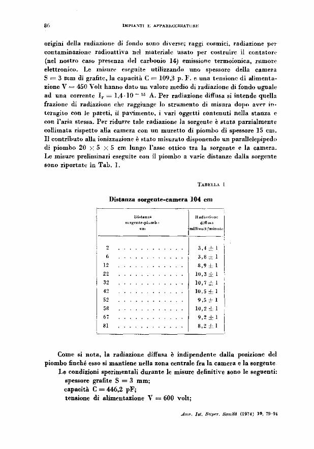
or1gmt della radiazione di fondu sono diverse; raggi cosmici, radiazione per contaminazione radioattiva nel materiale usato per co~>truire il contatore (nel nostro caso presenza del carbonio 14) emissione termoionica, rumor~· elettronico, Le misur~· eseguite utilizzando uno spessore della camera S = 3 mm di {!tafitc, la capacità C= 109,3 p.}'. e. una tensione di alimentazione V = 450 V oh hanno dato un valore medio di radiazione di fondo uguale ad una corrente 11, = 1,4 ·lO- IJ A. Per radiazione diffusa si intende quella frazione di radiazione che raggiunge lo strumento di misura dopn aver interagito con le pareti, iJ pavimento, i vari og~etti contenuti nella stanza c con l'aria stessa. Per ridurre tale radiazione la sorgente è stata parzialmente collimata rispetto alla camera con un muretto di piombo di spessore 15 cm. Il contributo alla ionizzazione è ~tat.o misurato disponendo un parallclepipedo di piombo 20 >: 5 X 5 cm lun~o l'asse ottico tra la sorgente e la camera. Le misure preliminari eseguite con il piombo a varie distanze dalla sorgente sono riportate in Tab. l.
Distanza sorgente-camera 104 cm ,--------c-----·
l>i.tooza
•u<g•nt<·piu"' b·>
'"'
nod·.-,,;,,, l diffu,a
mlllivolt/rnin"'",
---------~----'
' ,, 12
22
32
" 58
67
81 l
3' 4 :~~ l
3,8 :;:;- l
8,9 :L l
10,3 i.: l
lO, 7 .:: l
10,5 ±l
9,5-f-l
10,2 :!.: l
9,2 ±l
8,2 ::!-. l
Come si nota, la radiazione diffusa è indipendente dalla postzmne del piombo finché esso si mantiene nella zona centrale fra la camera e la sorgente
Le condizioni sperimentali durante le misure definitive sono le seguenti: spessore grafite S = 3 mm; capacità C = 446,2 pF; tensione di alimentazione V = 600 volt;
.A .. n. lat. Stl}wr. So.,ild (1974) IO, 79-94
: l
l
CREMOI'IESE, PUGLUNI E RlDOLFI
distanza sorgente-camera (45-60-81-100 cm); distanza sorgente-piombo (18-26--40).
87
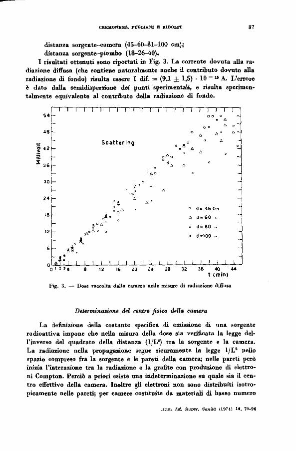
I risultati ottenuti sono riportati in Fig. 3. La corrente dovuta alla ra~ diazione diffusa (che contiene naturalmente anche il contributo dovuto alla radiazione di fondo) risulta essere I d.if. = (9,1 ± 1,5) · lO- 16 A. L'errore è dato dalla sem.idispenione dei punti sperimentali, e risulta sperimen· talmente equivalente al contributo della radiazione di fondo.
" .. ~ 42
Scattering
2B
, a" . '
o o , . '
o d= 4Gcm
.:'> d:: 60
d: 80
d=lOO
36 40 44 t (min)
Fig. 3, - Do8e raecolta dalla camera nelle misure di radiazione diffu&a
Determinazione del centro fisico della camera
La definizione della costante specifica di emissione di una sorgente radioattiva impone che nella misura della dose sia verificata la legge del• l'inverso del quadrato della distanza (1/V) tra la sorgente e la camera. La radiazione nella propagazione segue sicuramente la legge lfL2 nello spazio compreso fra la sorgente e le pareti della camera; nelle pareti però inizia l'interazione tra la radiazione e la grafite con produzione di elettroni Compton. Perciò a priori esiste una indetenninazione su quale sia il centro effettivo della camera. Inoltre gli elettroni non sono distribuiti isotro• picamente nelle pareti; per camere costituite da materiali di basso numero
.!nn. I!Jt. Super. Sanità (l9H) 11, 79--U
UU>JA!';T! E Al'PAliECçJIIATI"I\1
atomico il contributo alla ionizzazione totale dato dalla parete frontak (verso la sorgente) è predominante (CoRMACK & ]OHNS, 1954; HINE, 195~;
KONDO & HANIJOLl'II, 1960; BuRLL'\", 1964). Nel caRo dd radio e di cam<:>r•· in ~rafite il contributo portato alla ionizzazione dalla parete frontale è HU·
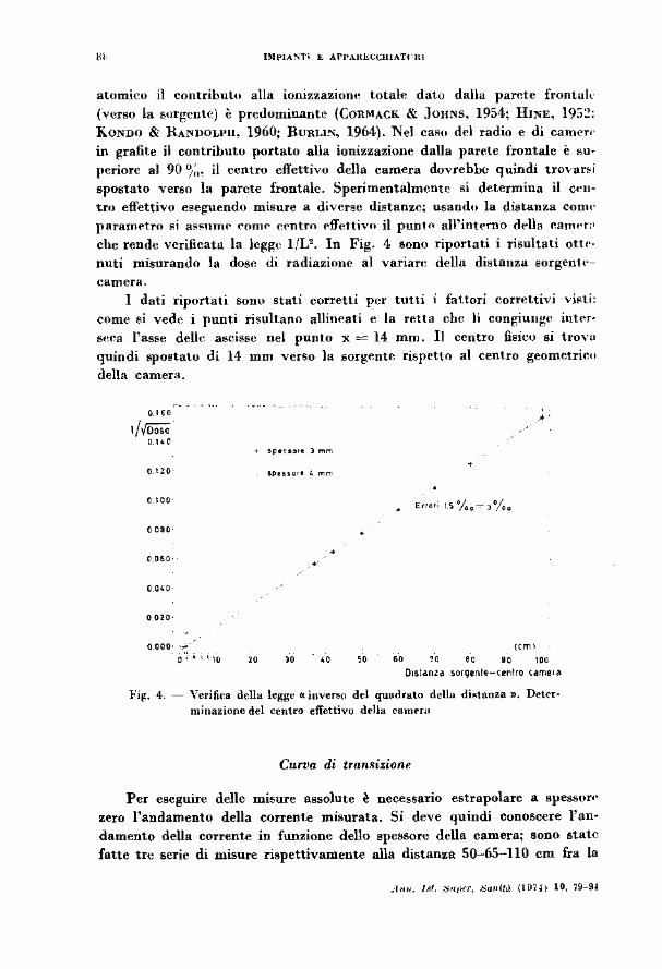
periore al 90 %· il centro effettivo della camera dovrebbe quindi trovar~ i spostato verso la parete frontale. Sperimentalmentt~ si determina il cen· 'tru effettivo eseguendo misure a diverse distanze; usando la distanza comt· parametro !!i al'l!'nmr- r-omr- c('ntro l"ffettivn il punH• al\'intt"rno ddla camt>r;•
che rende verificata la lc~ge 1/V. In Fig. 4 sono riportati i risultati ottt•nuti misurando la dose di radiazione al vanan: della distanza sorgentt·
camcra. I dati riportati sono stati corretti per tutti i fattori correttivi vi!'ti:
come si vedr- i punti risultano allin .. ati e la retta che li congiunge intN· seca l'asse delle ascisse nel punto x= 14 mm. Il centro fisico si trova quindi spostato di 14 mm verso la sorgente rispetto al centro geometrico
della camera.
•
o 120-
o l 00
o 080
•
o 040
o 010
0.000· ,..-~ o·; i c ( 10
" " .. .. '" '" •• '"" Otstanz~ sorgente-c~ntro cameoa
l'il(. 4. - Yerifica drlla legg~ «inverso del quadrato della dista.m:a ». Deter· minazione del centro effettivo delia camrw
Curva di tran.~izionr
Per eseguire delle misure assolute è necessario estrapolare a spessor•· zero l'andamento della corrente misurata. Si deve quindi conoscere l'an· damento della corren'te in funzione dello spessore della camera; sono state fatte tre serie di misure rispettivamente alla distanza 50-65-110 cm fra la
.l""· /.<1. /:jriJifr. Jja>dtà (197.1) 10, 79-94
çREMONESE, PlJGLIANl E RIDOLFI 89
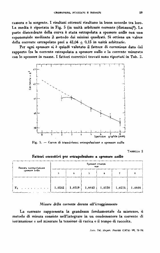
camera e la sorgente. I risultati ottenuti risultano in buon accordo tra loro. La media è riportata in Fig. 5 (in unità arbitrarie co l'l'ente (distanza}~, La parte discendente della curva è stata estrapolata a spessore nullo con una esponenziale mediante ù metodo dei minimi quadrati. Si ottiene un valore della corrente estrapolato pari a 42,04 ± 0,15 in unità arbitrarie.
Per ogni spessore si è quindi valutato ù fattore di correzione dato dal rapporto fra la corrente estrapolata a spessore nullo e la corrente misurata con lo spessore in esame. l fattori correttivi trovati sono riportati in Tab. 2.
F,
--,----,- ~-r----, ----,--r---1
"l . . ~
" l c j
' l l o l • "' 1- " c
J o l ' u
l ' l
1 ~ ~ l
·~ l
" ~__L
" ' ; ' Spe550re ' • grafite (mm)
Fig. 5. - Curva di tran~izione; estrapolazione a spes.ore nullo
T.!.BELLA 2
Fattori correttivi per estrapolazione a spessore nuUo
Speooorl ca,.eu l F"'t<><e eotrapol.z.io~e
,pe,.ore nullo ----,--~--,'"-----,--1 ' ' --+--l
1.0242 1,0319 l ,0143 l ,\1520 l.\16841 _ _c_.____.l
1,\1574
1\fisure della corrente dovuta alt'irraggiamento
La corrente rappresenta la grandezza fondamentale Ja misurare, il metodo di miau<a conoiate nell'integme in un conden.ato<e la conento Ji ionizzazione e nel misurare la tensione di carica e il tempo di raccolta .
. bm. Ist. /!:,'uper". Sanità (IIIH) lO, 79-94
911 DIPIANTI B APPARECCHIA.TUBE
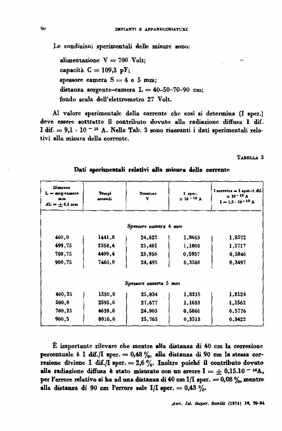
Le condizioni sperimentali delle misure sono:
alimentazione V = 700 Volt;
capacità C = 109,3 pF;
spessore camera S = 4 e 5 mm;
distanza sorgent~amera L= 40-50-70-90 cm;
fondo scala dell'elettrometro 27 Volt.
Al valore sperimentale della corrente che così si determina (I sper.) deve essere sottratto il contributo dovuto alla radiazione diffusa l dif. l dif. = 9,1 · lO- l& A. Nella Tab. 3 sono riassunti i dati sperimentali relativi alla misura della corrente,
TABELLA. 3
Dati .sperimentali relativi alla misura della corrente
Dlouu ... L __ ,.., ... u• ..... TeiUioue I '~""'·
I corretta - l oper.-1 dlf • x )Q•lt.A
•• -di v x lt)"lliJ,. 1-l,S•IO"UA .dL-±O,S.,.m
Spn1ure eam.era 4 mm
.00,0 1441,8 24,622 1,8663 1,8572 499,75 2358,4 25,481 1,1808 1,1717
700,75 -«09,4 23,956 0,5937 0,5846 900,75 7460,0 24,495 0,3588 0,3497
S~fMlre camera 5 mm
400,25 1550,0 25,834 1,8215 1,8124
500,0 2595,6 27,677 1,1653 1,1562 700,2S 4639,8 24,903 0,5866 0,5776
900,5 8016,0 25,765 0,3513 O,M22
:t importante rilevare che mentre alla distanza di 40 cm la correzione percentuale è I dif./I sper. = 0,48 %, .Ua distanza di 90 cm la Btel8a correzione diviene I dif.{Isper. = 2,6 %· Inoltre poiché n contributo .dovuto alla radiazione dift'uea è stato misurato con un errore I = ± 0,15.10 - "A, per l'errore relativo li ha ad una distanza di .W ern I(I sper. = 0,08 %, mentre alla distanza di 90 cm l'errore N1e lflaper. = 0,43 %·
l ' L
CRE!IONESB, PUGLIAl'll E RIDOtai 91
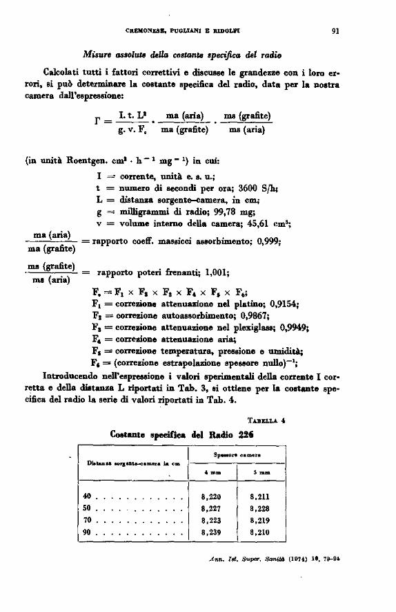
Misure ossolw. deUa costante specifica del radio
Calcolati tutti i fattori correttivi e discusse le grandezze con i loro errori, si può determinare la costante specifica del radio, data per la nostra camera da1l'espresrione:
l. t. L1
g. v. F. ma (aria)
ma (grafite)
ma (grafito)
ms (aria)
(in unità Roentgen. cm1 • h- 1 mg- 1) in cui:
ma (aria)
ma (grafite)
... (grafito)
nu (aria)
I = corrente, unità e. s. u.; t = numero di secondi per ora; 3600 Sfh; L = distanza sorgente-camera. in COli
g = milligrammi di radio; 99,78 mg; v = volume interno della camera; 45,61 cm5;
= rapporto coetf. massicci assorbUnento; 0,999;
= rapporto poteri frenanti; 1,001;
F.= F1 x F1 x Fa x F• x F, x F6;
F 1 = correzione attenuazione nel platino; 0,9154; F1 =correzione autoassorbimento; 0,9867; F 1 = correzione attenuazione nel plexiglass; 0,9949; F. = correzione attenuazione aria; F1 =correzione temperatura. pressione e mnidità; F, = (correzione estrapolazione speseore nullo)-1;
Introducendo nell'eepreaeione i valori sperimentali della corrente I cor• retta e della diatanza L riportati in Tab. 3, ei ottiene per la costante spe· ci&ca del radio la serie di valori riportati in T ab. 4.
TABBLLA 4.
Costante epeeilica del Radio 226
Sp-01'0 camer•
DlotaD.oa OO>JOD-•m••• la em
l • •• ... .. . 8,220 8,211 50 . 8,227 8,228 70 . . 8,223 8,219 90 8,239 8,210
Anll- Illl. Supet>. Sanità (19U) te, 79-94.
92 DfPIANTI E APPARJ;:CCWATURE
Il valore di r è stato determinato attraverso una misura indiretta (o assoluta): esso viene espresso attraverso una relazione matematica del tipor= r (xl, x2, ... x,.) dove xl, x,;, ... x,. sono le quantità che effettivamente vengono calcolate o misurate (nel nostro caso rappresentano i termini che appaiono nell'espressione della costante specifica).
Poiché gli errori sulle singole quantità non sono omogenei fra di loro essi sono stati trattati in modo da poter utilizzare, nel calcolo dell'errore totale finale, la legge della propagazione casuale degli errori, data dalle espressioni
(Jr)' ~ ...: (dx,)' . [ or (x,)]' L {}x1 '~ '
Jr r
' j' j • D (xr,)
~1: L.f dx, ~ , s 1 )_ r
Eseguendo il calcolo si ottiene per tutte le distanze (40-50-70-90 cm) che l'errore relativo è inferiore all'l%· Nel considerare il rimltato definitivo occorre tener presente infine che fra la taratura della sorgente e le misure sono trascorsi esattamente 4,2 anni; c'è quindi da apportare una ulteriore correzione per il decadimento della sorgente atessa (tenendo presente che il tempo di dimezzamento del radio è 1600 anni). Si ottiene un fattore correttivo F4 = 0,9982.
In definitiva, mediando sulle diverse distanze i valori ottenuti con due spessori della camera, otteniamo per la costante specifica del radio valori:
4 mm = 8,242 ± 0,07
5 mm = 8,232 ± 0,07
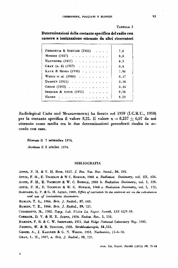
Nella Tab. 5 è riportato un quadro generale delle detenninazioni della costante specifica del radio con camera a ionizzazione ottenute da altri ricercatori.
ATTIX & RITZ (1957) hanno analizzato le varie determinazioni e dedotto per la costante specifica un valore compreso fra 8,2 e 8,3. Successivamente l'I.C.R.U. (National Bureau of Standards - lnternational eo....ission on
Ann. Jet. 8upllr. SanWl (HIU) 11. 79--9&
l l
J
CREMONESE, PUGLlANI E RIDOLFI
TABELLA 5
Determinazioni della costante specifica del radio con camera a ionizzazione ottenute da altri ricercatori
FRIEmncu & ScuuLzE (1935)
:\liNDER (1937)
MAYNEORD (1937)
GRAY (a, b) (19.~7)
KAYE & BINKS (1n8)
WmTE et al. (19·\0)
DARDE:'i (1951)
Guosu (19S3) .
SPENCER & ATTIX (l9S5)
HENRY , ,
7,8
R,O
8,3
8,4
7,96
8' ~ 7
1!,.~8
8 ,·14
8,26
fl.H
93
Radiological Unita and Measurements) ha fissato nel 1959 (LC.R.U., 1959) per la costante specifica il valore 8,25. Il valore x = 8,237 ± 0,07 da noi ottenuto come media tra le due determinazioni precedenti risulta in accordo con esso.
Ricevmo il 7 settembre 1974.
Accellalo il 2 ottobre 1974.
BIBLIOGRAFIA
ATTIX, F. H, & V. H. RITZ, 1957. ]. Res, Nat. Rur. Stand., 59, 293.
ATTIX, F. H., E. TocmLIN & W C. RoEscu, 1968 a. Radiation D~imetry, vol. 111, 624.
ATTIX, F. H., E. TOCHILIN & W. C. RoEScu, 1968 b. Radiation Dosilnetry, vol. l, 128.
ATTIX, F. H., E. TocmLIN & W. C. RoEsCH, 1968 c. Radiation Vo.•imetry, vol. l, 122.
HARNARD, G. P. & G. H. AsTON, 1960. Effect oft•ariatinn in lh6 ambient air "" 11w mkul«liuro
and use af ianizations do$imeter$.
8URLIN, T, E., 1964. Brii. ], Radiai., 37, 693.
BURLIN, T. E., 1966. Brit. }. Radiai., 39, 727.
CmozzOTTO, M., 1962. Rapp. Lab. Fioica Isl. Super. Sunità, lSS 62/9-lO.
CoRMACK, D. V. & H. E. JouNs, 1954.. Radiat. Res., l, 133.
lhRDEN, F, B. & C. W. SBEPPARD, 1951. Oak Rùlge Nalional Lahoratory Rep. 1002.
FRIEDIC, W. & R. 5CIIULZE, 1935. Strahlefllherapi., 54,553.
Guosu, A., j, KASTNER & G. :i. WmTE, 1953. Nucleanics, 11-6-70.
GuY, L. H., 1937, a. Dri1. J, Radiol., 10, 721.
Atm. Ist. Supe~. Sanlià (1974.) U, 79--9'
'
---~·--
9·l IMPIANTI E APPARECCHIATURl:
GRJ~.Y, L. H., 1937, b. PrQC. Ruy. So~. (London) (A), 159, 21d.
HENIIY, W. H., 1957. Can. ], Phys., 36, 149.
HtNF., G. )., 1952. Nu.cùonics, 10, 9.
HUBBELL, ). H., 1969. N.R.D.S.-N.B.S.-29-1969.
I.C.R.U., 1959. Harulbook 711.
K.AYE, G. W. & W. BINKS, 1938. Amer. ], Roentj(eno/. Radium Therapy, 40, 81).
KoNDO, S. & M. L. R.ANDOLPH, 1960. Radiat. Re.•., 13, 37.
MAYNEORD, W. V, & J. E. RoBERTS, 1937. BriJ. ]. Radio/., 10, 36:;.
MINDEn, W., 1937. Ac!a Radio/., 17, 76l.
MtssONI, G. & L. PUGLIANI, 1966. Ann. 1~1. Supcr. Sanilà, 2, 731. 752.
PoLI CASTELLANI, G., 1964. Rapp. Lab. Fisica 1st. Super. Sanità, ISS M/~.
5PENCEB, L. V, & F. H. A'JTIX, 1955. Rad. Res., 3, 239.
WHITE, T. N., L. D. MARINELLI & G. F .. ULLA, 1940. Am. ], RaenJ.~enol, Radium Therapy, "· 889.
YoUNG, M. E. J. & N. F. BATHO, 1964. Brit. J. Radio!., 37, 38 .
.Ann. IBI. Super. San«à (1974) le, 79--9'
' i
l CONFERENZE E SEMINARI
The Uppsala school in separation science and the development of bioallìnity chromatography(*)
JEB&EB. PORATH
In.tricute of Biodumifiry, UppM!la, Sweden
At the turo of this century P. T. Cleve and bis students were studying the rare earths and tranBition elements in Uppsala persuing traditions from Berzelius, Scheele and Bergman. One of the students, The Svedberg, became fascinated with colloid chemistry and particularly with the new theories put forth by Smoluchowski, Perrin and Einstein describing the kinetic behaviour of molecules and suhmicroscopical particles. Svedberg decided to make a contrihution in proving these theories and, for this purpose, be invented among other kinds of instruments the ultracentrifuge. Robin
·Faraeus was that time professar in physiology in Uppsala and had just introduced the sedimentation rate method of red blood corpuscles as a diag~ nostic. Among others be strongly influenced Svedberg to use the ultracentrifuge for the studies of proteina, the molecular size of which W88 un~ k.nown at that time. For the remainder of bis active time 88 a professor in physical chemistry, Svedberg divided bis interest between proteìn and polymer chemistry, O ne of bis many disciples, Ame Tiselius, chose to work in the former field and bis major contributions to protein chemistry in late 1920's and 1930's were focused on the development of boundary elèctro~ phoretical analysis of proteina. Tiselius later tumed to chromatography well realizing that isolation of the majority of proteina present in minute amounts in tissue extracts and serum required supplementary, more selective methods than those based on differential electrophoretic migration. He .~tarted with simple model systems such 88 amino acids, peptides, carbohydrates and aliphatic alcohols using charcoal as an adsorbent. Tiselius laid the foundation of some chromatographic techniques that are stili in
(•) LeetUR held at the Istituto Superiore di Sanità on October 24th, 1973.
Ann." !id, Supt:r. Sanità (IIIH) 11, 95-102
-----
96 CONFERENZE E SEMlNART
use today, such as frontal an d displacement ehromatography, Gradient elution which he and bis associates introduced in 1950, is in fact more popular than ever.
Thus Svedberg and Tiselius founded a school in Uppsala in separation science. After the retirement and death of these two great pioneers, Stellan Hjertén and I in Uppsala, Harry Svensson-R.IThe in Gothenburg and PerAke Alhertsson in Umea are following in their footsteps.
Together with Per Flodin, I introduced gel iiltration or gel permeation chromatography in the 1950's (1). My first experiments were with granular starch in 1953 but tbc break-through came with the use of cross-linked dextran now called Sephadex. Poulsen, a South-african biochemist, and one of Svedberg's pupils (2) and Hjertén (3) extended the field of molecular size chromatography by introducing agar and agarose respectively as chromatographic media. W e became interested in the nse of agarose for the synthesis of immobilized enzymes (4) and thus entered a fascinating field in which Dinelli, Marconi and their collegues bere in Rome recently bave made very substantial contrihutions. However, l will confine myself now to the use of a agarose as a base for biospecifìc ad.sorbents (4, 5). Before going into details of how we solved eome of the tecbnical problems of agarose gel chemistry l wonld lik.e to remind you of the fractionation problems in immunochemistry.
Elvin Kabat and Michael Heidelberger were visiting research guests in Uppsala in 1930's. Tiselius and Kabat di8covered that the y-boundary proteine were associated with the antibodies which were consequently called y-globulins. Since it was known that there are thousands of antibodies in serum, it was obvious that more selective methods were necessary for major advancement in tbc chemistry of these highly important proteins. An attractive solution to the problem is to make uee of the specificity cha· racteristic of the antigen-antibody complex form.ation. This has been known for well over half a century. Efforts were made in 1940's and 1950's to use immunosorption but success was not impressive.
The problems of enzyme isolation may be tackled in an analogous fashion by making use of the high specificity in form.ation of enzyme-sub· strate or enzym.e-inhibitor complexes (5). In fact whenever a dissociable complex is form.ed, one of the complex partners may be isolated or at least purifìed by adsorption and eubsequent desorption from a gel to which the complementary partner has been fixed preferably by a covalent bond. In 1959 I started some work along these linea. I realized that much fondamenta! work was needed before successful applications in generai could be expected. AB matrix substance cellulose and the newly discovered Sephadex were tried. Among early attempts I may mention that Roberto Strom from Rome tried to prepare an adsorbent for succinic dehydrogenase by
..4."". I.t. Supq. SanUd (1117!) lt, 115--102
PORATB 97
attaching a succtmc acid ligand to Sephadex. Somewhat better results were obtained with biotin-Sephadex for isolation ofhiotin from egg-white (6). Much developmental work waa necessary (7).
Let U8 first consider some of the conditiona for chromatography based on apecifi.c complex formation. For successful application of bioaffinity chromatography it is necessary to find:
l) a carrier or matrix meeting a number of specified requirements, I will shortly mention;
2) a method for introduction of the ligand or the substance to form the specifìc adsorption center in the matrix;
3) chromatographic conditiona for efficient adsorption and desorption with regeneration ofthe adsorbent and high, preferably quantitative recovery of the substance to be purified or isolated.
I conaider the introduction of gels for molecular sieving as a stage in tbe development of bioaffinity chromatograpby. The ideai molecular sieve is also the ideai matrix for biospecific adaorption. More than a decade of efforts finally resulted in the now available materials and methods which stili bave to be further developed. The matrix should be insoluble and mecbanically rigid and preferably in tbe form of spberical beads. A prerequisite is of courae premeability to make possible not only in and out dif. fuaion of ligand an d adsorba te suhatances but also tbeir interaction to form the required specific complex or complexes. The matrix must be hydrophilic in nature and nonadsorbing. In addition it should be chemically resistant to chromatographic media yet convertible into reactive form(s) that permits ligand attachment.
W e bave found cross-Iinked agarose, desulpbated in strong alkali, to most closely approach the ideai matrix (8). The gel is practically insoluble even at elevated temperature and can be safely autoclaved without cbange in the physical appearance. Tbe beads retain their sbape. There are reasons to believe that agarose and agar gela are fundamentally different in tbeir tertiary structure from macro--reticular syntbetic polymers and that they are better suited for our purpose. The permeability is only moderately affected by cross--linking aa sbown by the fact that particles such as poliovirus can effectively permeate extensively cross-linked 2 % agarose. Since the matrix itself is of natural origin and consista of polygalactane, it is conceivable that substances whicb form complexes with galactose should be adsorbed to agar gel in the same way substances fonning complexes with glucose can be adsorbed to Sepbadex. Tbis kind of specific adsorhtion has heen used to isolate glucose---specific lectins from common vetcb, Vicia cracca (9) and concanavalin from Concanavalia ensiformis (10). The lectin forma an adsorption complex witb the dextran chains of the matrix. By introducing
.Jnn. 181, S"pu. Sanità 09Hl lt, 95-102
CONFERENZE E SEMINARI
glucose in the buffer the protein is specifìcally eluted from the gel. Spe· cific adsorption followed by specifìc desorption is particularly effi.cient and may yield purifi.cation factors of !leverai thousands.
In generai, however, the 11pecifìcally interacting suhstance must be introduced in 11ome way into the gel and this has been another bottle-neck problem. By a fortunate accident we stumbled upon an excellent method of attaching ligands. Axén, Ernhack and l found that cyanogen bromide converted the matrix into a reactive form that permits proteins and amino group containing substances in generai to be covalently attached to agaros(· and other hydroxylic polymers (4, 11). The intermedi ate substituent formed is imido carbonate and this can react -with amines to form substituted imido carbonate esters, isoureas and carbamates. They are ali sutlìciently stable to meet most demands. W e originally used this method and agarose gel for production of immobilized enzymes but soon also applied it for &ynthesis of adsorbents (4, 11). Cuatrecasa.s et al. using our method coined the term « affinity chromatography » and demonstrated how enzymes can be purifìed on substrate analogue adsorbents. They also demonstrated that the matrix may constitute a sterical hindrance for adsorption which can be overcome by inserting an arm or spacer between tbc ligand and the matrix. W e bave recently introduced a number of otber methods for ligand attachment in bydrophilic gels. One of those methods, the isocyanide procedure, is based on the Ugi four component reaction (12, 13). By this method attachment can be madc not only via àmino--groups but also through carboxyl or carbonyl groups.
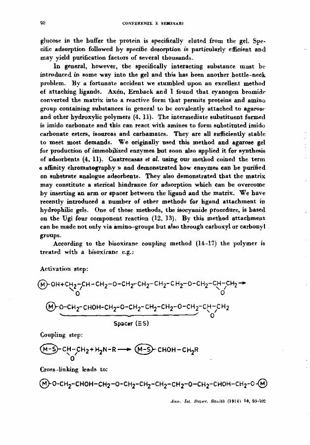
According to the bisoxirane coupling method (14--17) the polymer is treatf'd with a bisoxirane e.g.:
Activation step:
Q_ OH+CH2-CH- CH2-o-CH2-CH2- C Hr C H2-o-CH2-CH -CH2-\!:.:./ ' l ' l o o
@-o-CH2- CHOH-CH2-0-CH2- CH2-cH2-0-CH2-C~ -1C H2
o Spacer (;: S)
Coupling step:
@c~-pH2+H2N-R- @cHOH-CH2R o
Cross-linking leads to:
@-0-CH2-CHOH-CH2-0-CH2-cH2-CH2-cH2-0-CH2-CHOH-CH2-o-@
A,.n. Ist. Sll/><'r. Smdt<'r (19Hl lO, 9;)-102
POB.ATB 99
Amines and alcohols can thus be coupled to form extremely stable substituted amines or ethers. Of particular importance is the simultaneous introduction of a long hydrophilic spacer. Another method studied is based on the onesided reaction of divinyl sulfone with the matrhc (14, 15, 17):
@-oH+CH2=CH-S02-CH=CH2 - @-O-CH2-CH2-so2-CH=CH2
@-o-CH2-cH2-so2-CH=CH2+HOR-@-O-CH2-cH2-so2-cH2-cH,-OR
A.8 for tbe bisoxirane coupling, cross-linking will simultaneously occur. The coupled product is less stable but the cross-linking resulte in a very large increase in rigidity of the gel- a considerable advantage in cbromaro. graphy. The reactions witb am.ines aud alcohols take piace more readily tban with tbe otber metbods and we bave found the method particularly valuable for coupling carbohydrates to agal'Me. The two last methods descrihed are b88ed on the formation of intennediates which are stable enough to permit storage for very long periods of time. Another and more important advantage is the fact that no ionic groupe are introduced during the activation step. In the literature there ie an increasing num.ber of ap· plicatione of bioaffinity cbromatography to be found (18-24). The field is rapidly expanding and I sbould like only to give a few examples. In our studie8 on lectin8 we bave fonnd it expedient to use bio--specific adsorbente. I mentioned earlier the Vicia craeca lectin 88 an example. In most cases it is neceeeary to attach the carbohydrate forming the complex as a separate ligand ratber than to bave a specifically interacting matrix. For example, Crotalaria juncea bean lectin reacts specifically with galactose. One should tberefore expect agarose to be an efficient adsorbent in itself. Tbis is not at all the case because terminai galactoee residues are necessary for the fit in tbe com.bining site of the lectin. A weak adsorbent may be made by limited hydrolysis. A strong adsorbent with high capacity is obtained by attaching galactose or lactose (25) to cross--linked agarose with the bis• oxirane or divinyl sulfone method. In fact lactose-agarose has proved to be too strong for good performance, galactose is to be preferred 88 ligand. On passing Crotalaria bean extract througb a bed of the adsorbent only lectin will be retained and it is effectively eluted by including lactose in the buffer. :More than 200 times increase in activity is obtained in one step whicb yields the lectin in pure state. The column may be used repeatedly as it seems to bave virtually unlimited durability.
Lectins such as concanavalin A and Crotolaria junceo leetin may now be attacbed to cross--linked agarose to give adsorbente specifi.e for poly-
Ann. I~l. Suptr. San\tà (111U) 10, 9!.--102
100 CON-fERENZE E SEMINARI
saccharides and glucoproteins. By using two or more adsorbents differing in specificity in sequence rather efficient fractìonation of extracts and bio· logica} fluids can be achieved in a single stage if the columns are couplcd in serìes. For example, Crotalaria lectin gel adsorbs ~2-lipoproteins, some y-globulins and IXcmacroglobulin. In addition to tbese substances, concanavalin lectin agarose adsorhs transferrin and a number of other minor components in the serum. Our goal is to develop a series of hìospecific adsorhents for ali common monosaccharides and their polysaccharides and protein derivatives.
Among other systems we studied in some detail I like to mention pancreatic juice (14, 15). Crude pancreatic extract is allowed to pass a column of agarose to which soy-bean trypsin inhibitor has been coupled. Trypsin, chymotrypsin and some other minor components are adsorbed. Use of low molecular weight inhibitors in large excess of the ligand of higher aflinity will elute the enzymes selectively: tryptamine displaces chymotrypsin and benzamidine in turo trypsin. The substance then left on the column can be eluted non-specifically by lowering the pH.
The isolation of human carbonic anhydrase with suHanilic amide agarose and Sephadex (26) can be mentioned as an example with a low molecular weight ligand formìng a strong complex with a protein. There are two clefts in the enzyme molecule that fit the suHanilamide, one of them forming the active site of tbe carbonic anhydrase. In human erythrocytes there are two isozymes called B and C of partly different amino acid composition. The bulk of proteins, Of course, consists of bemoglobin which passes tbrough the chromatographic bed without being retained. The two isoenzymes are adsorbed and can be subsequently eluted by potassium iodide and isocyanate respectively.
Recently Mosbach and bis group in Lund, Sweden (27) and Barry and O'Carra, Galway, lreland (28) bave bound nucleotides to agarose via spacers for the isolation of cofactor dependent enzymes. Mosbach and coworkers were able to separate the five isozymes of lactic dehydrogenase by means of cofactor concentration gradients. W e bave not yet entered this Jìeld in Uppsala.
Many attempts are now being made to utilize bioaflinity chromatograpby for isolation of bormone receptors. lt is likely that this selective kind of chromatography will prove itself extremely valuable but l think tbat con· siderable improvements are stili needed both with respect to the properties of the adsorbents and particularly tbe technique of elution until tbc methods approacbes the limits of its potentialities. Recently the interest has been raised for hydropbobic adsorption and its use for chromatographic separation of proteins. Adsorbents with amphiphilic (amphipatic) properties may perbaps be useful adsorbents for membrane bound proteins, lipoproteins,
.Ami. Isl. Supcr. Sa<iitd (1974) 10, 95-102
PORATB 101
glycolipida and other substances less easily purified and handled than those hithertofore studied.
Bioaffinity chromatography also provides ua with methoda for the study of molecular interactiona between proteina, nucleic acida and Iow moJecular weight aolutea. These studies bave hardly begun but they are lik:ely to be rewarding particularly if a satisfactory theory can be work.ed out.
In concluaion: bioaffinity is likely to be much used in basic biochemistry and related fields for isolation of molecular speciea of small and large size molecular aggregatee, membrane fragments subcellular particles, virus and cella. Chromatography will often be required but when diffusion ratea set the limita batch-wise operations may be necesaary. For the study of bio~ structures of higher order with bioaffinity adsorption it will be necessary to improve the methode now available and this can only be done if they are developed in parallel and in close connection with attempts to solve basic problems in biochemistry.
REFERENCES
(J) PORATB, J, & P. FLODIN, ;Valure, 183, 1657 (1959),
(2) POLSEN, A. Biochim. Biophy~. Aeta, 50, 565 (1961).
(~) PoRATH, J,, R. AxEN & 5. ERNBACK, Nat.un, 215, 1491 (1967).
(5) CUATRECA.SAS, P., M, Wncou & C. B. ANFINSEN. Proc. Nal. Acad. Sei. U. S. A.., 61, 636 (1968).
(6) PoRATH, J. In; N...bel Sympo.~ium 3, Gamma Globuiiru p. 287 (1967), J. Killander, Ed. Almqvist et Wiksell, Stockholm and 1ntencience Publishen, New York, London, Sidney.
(7) PoRATD, J, .'Vat.UTil, 218, 834 (1968).
(8) PORATB, J., J.-C. ]ANSON & T. LAAs. ]. Chromalogr., 60, 167 (1971).
(9) AsPBEBG, K., H. HoLMRI"' & J, PORATB. Biochim. Biophy&, Ado, 160, ll6 (1969).
(IO) AGRAWAL, B. B. L. & I. J, GoLDsTEIN. Biochem. ]., 96, 23C (1965).
(li) AxEN, R., J. PoRATH & S. ERNBACK, Nat.ure, 214, 1302 (1967).
(12) AXEN, R., P. VRETBLAD & j. PoRATH, Acto Clulm. SconJ., 25, 1129 (1971),
(13) AxEN, R. & P. VRmDLAD. In: Prolitk• of 1M Biologieal Fluid&, 18, 383 (1971), H. Peeten, Ed., Pergamon Preu, Oxford and New York.
(14) PORATH, J, & L. SuNDBEBG. In: Protide& o/W BWiogical Fluid•,18, 401 (1971). H. Peeten, Ed., Pergamon Press, Oxford and New York.
(15) PORATH, j, & L. SUMDBEBG, In: T1w Chmnimy of Bio3urjau8, 2, 653 (1972). "· Hair Ed., .M. Dekker Ine., New York 1972.
(16) 5UNDBERG, L. & J, PORATH. J. ChromoWgr., 90, 87 (1974).
{ l7) PORATH, J, in: Melho.U in Emynwlo1Cf, EM)'lll• Purijkotion, P art B, A.Jfinity Me1/wd,, W. B. Jakoby & :Y:, Wilchek, Ed8., Academic Pre8R, in preu.
(18) CUATRECASAS, P. & C. B. ANFINSEN. Melhofù Enzymol., 22, 345 (1971).
(19) FRIEDBERG, F. ChromoWgr. Roo., 14., 121 (1971),
(20) PORATH, J. BioehimU, 55, No. 8, 943 (1973) •
. l<m. Isf. Super. Sanita {1974) IO, 95-102
102 WNJI'EIIENZE E !iEJUNAJU
(21) TUUOVA, j. ). Chrom.tJWsr., 91, 267 (1974).
(22) PoliA.Til, J. & T. KBisTUJ'fliEN. In: TM Prouim, 3rd ed., H. Neurath IIIld R. Bill, Eds • Aeademic PreBB, New Ycn:k and London, m press.
(23) O'CA.BllA, P. lnd.utrUd A.apt~c&s of Biot:Mmi#ry, B. Spencer, Ed., FEBS, 107.
(24} WILLUXS, K. W. Lab. Pract., 12, 8, 591 (1973).
(25} Ea&soN, B. & J. PollATB (1974} to be puhliJherl.
(26) F.u&BBING, S. 0., P. 0. GoTn, P. 0. NYJCA..N", L. SuNDBEBG & J. Poum. FEBS lAna, U, 229 (1972).
(27} MOSBACB, K., H. GuU.J'OilD, R. 0BLSSON & M. ScOTT. Biochem. J., 1!7, 625 (1972).
(28) BAlt.BY, S. & P. O'CAIIRA. Biochem. )., 135, 595 (1973) .
..tnn. Illl. Suver. &mil<l (19H) 11, 115-10'.!