Embed Size (px)
Citation preview
Synthetic Metals 220 (2016) 653–660
Improved electroactive phase content and dielectric properties offlexible PVDF nanocomposite films filled with Au- and Cu-dopedgraphene oxide hybrid nanofiller
Parisa Fakhria,b, Haroon Mahmoodb, Babak Jaleha, Alessandro Pegorettib,*a Physics Department, Bu-Ali Sina University, Hamedan 65174, IranbDepartment of Industrial Engineering, University of Trento, via Sommarive 9, Trento, 38123, Italy
A R T I C L E I N F O
Article history:Received 26 July 2016Received in revised form 10 August 2016Accepted 12 August 2016Available online 21 August 2016
Keywords:Poly(vinylidene fluoride)Graphene oxideCopper nanoparticlesGold nanoparticlesElectroactive phaseDielectric constantDielectric loss
A B S T R A C T
In the present work, new and flexible poly(vinylidene fluoride) (PVDF) based nanocomposites containingAu- and Cu-doped graphene oxide (GO/Au and GO/Cu) nanosheets were prepared by solution casting. Theresulting nanocomposites present a high content of electroactive phases and high dielectric constantaccompanied with low dielectric loss which make them interesting for possible applications in sensorsand electronic devices. Fourier transformed infrared spectroscopy (FTIR) was used to study the crystallinestructure of nanocomposites which showed no absorption band related to non-polar a phase. FTIRconfirmed an enhancement of the electroactive phase with the increase in nanofiller concentration dueto the electrostatic interactions among the CH2-CF2 dipoles of PVDF and nanofiller. Electroactive phasecontent as calculated from FTIR spectra presented a maximum value of about 95% for PVDF filled with 1%GO/Au nanofiller. This value is about 2.5 times higher than that of neat PVDF. For a given fillerconcentration, nanocomposites filled with GO/Au showed a higher increase of electroactive phase incomparison with those containing GO/Cu. This trend was also confirmed by X-ray diffraction (XRD)spectra. From inductance, capacitance, and resistance (LCR) measurement, nanocomposites display highdielectric constant, increasing with the nanofiller content, and low dielectric loss which is favorable tofabricate flexible and simple high performance nanodielectric materials.
ã 2016 Elsevier B.V. All rights reserved.
Contents lists available at ScienceDirect
Synthetic Metals
journal homepage: www.elsevier .com/ locate /sy nmet
1. Introduction
The most well-known ferroelectric polymer, poly(vinylidenefluoride) (PVDF) has attracted increasing attention due to itsamazing electroactive properties such as piezoelectricity andpyroelectricity [1–3]. Due to these properties combined with itslow cost, ease of processing and flexibility, applications of PVDFhave been increased enormously in various fields such as sensorsand actuators [4–7]. However, PVDF exhibits piezoelectricproperties only in its b and g electroactive polar crystallinephases as compared to the nonpolar a-phase. In fact, PVDF is athermoplastic semicrystaline polymer that can crystallize in fourdifferent phases; a, b, g and d depending on the macromolecularchain conformations. Among these phases, b and g phases play aspecial role due to their peculiar piezoelectric properties, although
* Corresponding author.E-mail addresses: [email protected], [email protected]
(A. Pegoretti).
http://dx.doi.org/10.1016/j.synthmet.2016.08.0080379-6779/ã 2016 Elsevier B.V. All rights reserved.
the b phase is more polar than the g phase. Unfortunately, themore common form of PVDF crystals is the nonpolar a phase,because it is thermodynamically more stable in PVDF than theother phases and it is therefore relatively easy to obtain a phasedominant PVDF films. The polar phases cannot naturally formalthough the g phase is more thermodynamically stable than the bphase. However, the nonpolar phase can be converted into polarphases [8–10]. As a consequence, so far numerous research workshave published on the possible methods to transform nonpolarphase to polar phases in PVDF, including mechanical stretching,polarization, electrospinning and several others [11,12]. However,these methods have obvious limitations that make them undesir-able to prepare cost effective material especially at a largeproduction scale.
In more recent years, another possible approach to induceelectroactive phases in PVDF based on the dispersion of propernanofillers in the polymer matrix has been investigated [13]. Inparticular, much attention has been paid to increase the amount ofelectroactive phases by the addition of carbonaceous nanofillers
654 P. Fakhri et al. / Synthetic Metals 220 (2016) 653–660
such as carbon nanotube (CNT), graphene, graphene oxide (GO),reduced graphene oxide (rGO), etc. [14–16].
PVDF possesses outstanding dielectric properties that makes ita material having great potential for applications in MEMS devicesand in high charge-storage capacitors [17]. For PVDF polymer to beemployed as a functional material in these fields, it is required anenhancement of its dielectric constant. Dielectric constant can beenhanced by adding high dielectric permittivity ferroelectricceramics such as BaTiO3 [18,19], but the resulting material suffersfrom low flexibility, and poor mechanical performance [20]. Thebest way to increase the dielectric constant along with preservingits mechanical flexibility is by adding a conductive nanofiller,especially carbon based nanomaterial to the polymer matrix [21].The dielectric constant of composites can be significantlyimproved by adding only a small amount of expanded graphitenanoplatelets (xGnP) and rGO as reported in literature [22,23].However, the enhanced dielectric constant of these composite issimultaneously accompanied with high dielectric loss, which is notdesirable for practical applications. Some research works havebeen reported on the enhancement of dielectric constant with lowdielectric loss by adding carbon based filler to PVDF matrix [21,24]but the electroactive properties of PVDF, which is the mostimportant property of PVDF, has not been considered in thosereports. From a practical point of view, to preserve the applicationsof PVDF, it is important to consider both the electroactive anddielectric properties. Yang et al. [20] investigated the effect of TiO2/multiwalled carbon nanotubes (MWCNT) on ferroelectric anddielectric properties of PVDF, but only 3% change in polar phasecontent was reported.
In this study we report new, flexible, low cost and light weightGO/Au-PVDF and GO/Cu-PVDF nanocomposites having highcontent of electroactive phase and high dielectric constant alongwith low dielectric loss, which were prepared through a simplesolution casting method. Graphene oxide have been chosen as afiller due to its high surface area and aspect ratio and its versatilefunctionality attributed to the different attached functional groups[25]. Since GO is an electrically insulating material, due to itsdisrupted sp2 bonding networks, two different metal nano-particles, Au and Cu, separately have been attached on GO surfaceto increase the electrical conductivity of the filler. These nanofillerswere added to PVDF matrix at various concentrations. Themicrostructure, electroactive and dielectric properties of nano-composites were investigated and the effect of the two nanofillerswas compared. Since the electroactive properties of PVDF mainlydepend on the crystalline structure of the polymer, the effects ofthe selected nanofillers on crystallization process and crystallinityof the samples were also investigated.
2. Experimental
2.1. Materials and sample preparation
All chemicals and solvents were purchased from Merck andSigma Aldrich and were used without further purification.Synthesis of graphene oxide, Au nanoparticles and Cu nano-particles and also the preparation of nanofillers (GO/Au and GO/Cu) used in present work have been described in detail in ourprevious works [26,27]. In the present work, GO/Cu was dispersedin N,N-dimethylformamide (DMF) using ultrasonication for60 min. Separately PVDF was dissolved in DMF with a mass ratioof 10/90 and stirred for 3 h to obtain a homogeneous andtransparent solution. The PVDF solution was then mixed withthe GO/Cu solution and the resulting solution was kept underultrasonication for 1 h. Afterwards, the well dispersed solution waspoured onto Petri dish and kept in an oven at 120 �C for 2 h for acomplete removal of the solvent. Finally, dried GO/Cu-PVDF
nanocomposite films were obtained. GO/Au-PVDF nanocompositefilms were prepared in the same way. Likewise, composite filmswith different GO/Cu and GO/Au loading (0.5, 1.0 and 5.0 wt.%)were prepared and coded as 0.5GO/Cu-PVDF, 1.0GO/Cu-PVDF,5.0GO/Cu-PVDF, 0.5GO/Au-PVDF, 1.0GO/Au-PVDF and 5.0GO/Au-PVDF, respectively.
2.2. Testing methods
The chemical information and modifications have beenassessed by FT-IR (Fourier transformed infrared) spectroscopy.Measurements were carried out using Varian 4100 FTIR (Excaliburseries) in transmittance mode with a resolution of 4 cm�1 andspectra wavenumber range between 4000 and 500 cm�1.
X-ray diffraction (XRD) data were acquired by an ItalstructuresIPD3000 instrument equipped with a multilayer monochromator.Spectra were collected by means of an Inel CPS120 detector overthe omega + 120� two-theta range. Different incidence angles weretested to maximize the signal coming from the deposition layer,with a final choice of 1�; acquisition time was 1800 s perdiffractogram.
Differential scanning calorimetry (DSC) analysis was performedby a Mettler DSC 30 calorimeter. All experiments were performedat a heating rate of 10 �C/min under a constant nitrogen flux of100 mL/min maintained during the tests in the temperature rangefrom 0 to 200 �C.
Thermogravimetric analysis (TGA) was performed with aMettler TG 50 thermobalance in the temperature range from 25up to 750 �C at a heating rate of 10 �C/min under a of nitrogen fluxof 100 mL/min.
The morphology of films was investigated by field emissionscanning electron microscopy (FESEM) with a Zeiss SUPRA 40microscope. A layer of platinum and gold was deposited onsamples prior to FESEM observations.
The measurement of relative permittivity and dielectric loss ofthe nanocomposite film were performed by an Agilent 4284Aimpedance analyzer in the frequency range from 20 up to 106Hz.
3. Results and discussion
3.1. Fourier transformed infrared spectroscopy
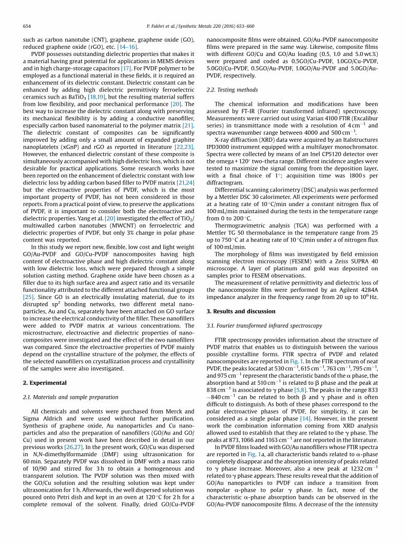
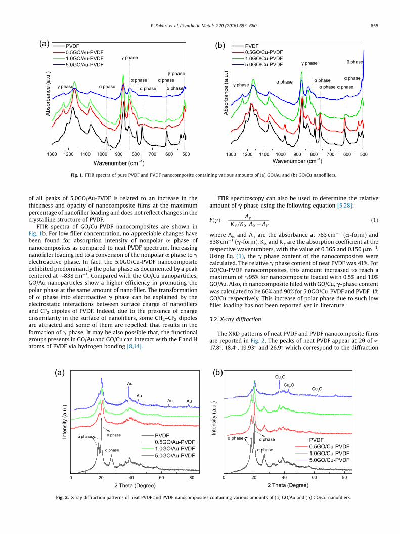
FTIR spectroscopy provides information about the structure ofPVDF matrix that enables us to distinguish between the variouspossible crystalline forms. FTIR spectra of PVDF and relatednanocomposites are reported in Fig. 1. In the FTIR spectrum of neatPVDF, the peaks located at 530 cm�1, 615 cm�1, 763 cm�1, 795 cm�1,and 975 cm�1 represent the characteristic bands of the a phase, theabsorption band at 510 cm�1 is related to b phase and the peak at838 cm�1 is associated to g phase [5,8]. The peaks in the range 833�840 cm�1 can be related to both b and g phase and is oftendifficult to distinguish. As both of these phases correspond to thepolar electroactive phases of PVDF, for simplicity, it can beconsidered as a single polar phase [14]. However, in the presentwork the combination information coming from XRD analysisallowed used to establish that they are related to the g phase. Thepeaks at 873, 1066 and 1163 cm�1 are not reported in the literature.
In PVDF films loaded with GO/Au nanofillers whose FTIR spectraare reported in Fig. 1a, all characteristic bands related to a-phasecompletely disappear and the absorption intensity of peaks relatedto g phase increase. Moreover, also a new peak at 1232 cm�1
related to g phase appears. These results reveal that the addition ofGO/Au nanoparticles to PVDF can induce a transition fromnonpolar a-phase to polar g phase. In fact, none of thecharacteristic a-phase absorption bands can be observed in theGO/Au-PVDF nanocomposite films. A decrease of the the intensity
5006007008009001000110012001300
γ phase
α pha seα pha se
α ph ase
α ph ase
Abs
orba
nce
(a.u
.)
Wavenu mbe r (cm -1)
PVDF0.5GO/Au-PVDF1.0GO/Au-PVDF5.0GO/Au-PVDF
γ pha se
(a)
α phase
β pha se
50060070080090010001100120 01300
α ph ase
Abso
rban
ce (a
.u.)
Wavenu mber (cm -1)
PVDF0.5GO/Cu-PVDF1.0GO/Cu-PVDF5.0GO/Cu-PVDF
γ pha se
γ pha se
α pha seα pha se
α phase
(b)
β phase
α pha se
Fig. 1. FTIR spectra of pure PVDF and PVDF nanocomposite containing various amounts of (a) GO/Au and (b) GO/Cu nanofillers.
P. Fakhri et al. / Synthetic Metals 220 (2016) 653–660 655
of all peaks of 5.0GO/Au-PVDF is related to an increase in thethickness and opacity of nanocomposite films at the maximumpercentage of nanofiller loading and does not reflect changes in thecrystalline structure of PVDF.
FTIR spectra of GO/Cu-PVDF nanocomposites are shown inFig. 1b. For low filler concentration, no appreciable changes havebeen found for absorption intensity of nonpolar a phase ofnanocomposites as compared to neat PVDF spectrum. Increasingnanofiller loading led to a conversion of the nonpolar a phase to gelectroactive phase. In fact, the 5.0GO/Cu-PVDF nanocompositeexhibited predominantly the polar phase as documented by a peakcentered at �838 cm�1. Compared with the GO/Cu nanoparticles,GO/Au nanoparticles show a higher efficiency in promoting thepolar phase at the same amount of nanofiller. The transformationof a phase into electroactive g phase can be explained by theelectrostatic interactions between surface charge of nanofillersand CF2 dipoles of PVDF. Indeed, due to the presence of chargedissimilarity in the surface of nanofillers, some CH2–CF2 dipolesare attracted and some of them are repelled, that results in theformation of g phase. It may be also possible that, the functionalgroups presents in GO/Au and GO/Cu can interact with the F and Hatoms of PVDF via hydrogen bonding [8,14].
0 20 40 60 80
Au
Inte
nsity
(a.u
.)
2 Theta (Degree)
PVDF0.5GO/Au-PVDF1.0GO/Au-PVDF5.0GO/Au-PVDF
α phase
AuAu Au
α phase α phase
(a)
Fig. 2. X-ray diffraction patterns of neat PVDF and PVDF nanocomposites
FTIR spectroscopy can also be used to determine the relativeamount of g phase using the following equation [5,28]:
F gð Þ ¼ AgKg=Ka� �
Aa þ Agð1Þ
where Aa and Ag are the absorbance at 763 cm�1 (a-form) and838 cm�1 (g-form), Ka and Kg are the absorption coefficient at therespective wavenumbers, with the value of 0.365 and 0.150 mm�1.Using Eq. (1), the g phase content of the nanocomposites werecalculated. The relative g phase content of neat PVDF was 41%. ForGO/Cu-PVDF nanocomposites, this amount increased to reach amaximum of �95% for nanocomposite loaded with 0.5% and 1.0%GO/Au. Also, in nanocomposite filled with GO/Cu, g-phase contentwas calculated to be 66% and 90% for 5.0GO/Cu-PVDF and PVDF-1%GO/Cu respectively. This increase of polar phase due to such lowfiller loading has not been reported yet in literature.
3.2. X-ray diffraction
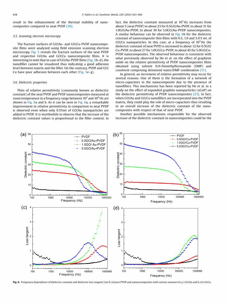
The XRD patterns of neat PVDF and PVDF nanocomposite filmsare reported in Fig. 2. The peaks of neat PVDF appear at 2u of �17.8�, 18.4�, 19.93� and 26.9� which correspond to the diffraction
0 20 40 60 80
α pha se
Cu2O Cu2O
Cu2O
α pha se
Inte
nsity
(a.u
.)
2 Theta (Degree)
PVDF0.5GO /Cu-PV DF1.0GO /Cu-PV DF5.0GO /Cu-PV DF
α pha se
(b)
containing various amounts of (a) GO/Au and (b) GO/Cu nanofillers.

Table 1Tm, Tc and Xc values of PVDF and GO/Au-PVDF and GO/Cu-PVDF nanocomposite filmat different nanofiller loadings.
Sample Tm(�C) Tc(�C) Xc(%)
Neat PVDF 161.1 130.0 580.5GO/Au-PVDF 166.3 131.3 561.0GO/Au-PVDF 167.5 132.5 525.0GO/Au-PVDF 166.3 133.0 520.5GO/Cu-PVDF 161.0 130.5 551.0GO/Cu-PVDF 161.0 130.7 525.0GO/Cu-PVDF 164.7 131.5 53
400 500 600
0
20
40
60
80
100
~
Wei
ght (
%)
Tempe rature (°C)
PVDF0.5GO /Au-PVDF1.0GO /Au-PVDF5.0GO /Au-PVDF0.5GO /Cu-PVDF1.0GO /Cu-PVDF5.0GO /Cu-PVDF
11 °C
Fig. 4. TGA thermograms of neat PVDF and relative nanocomposites with variousamounts of GO/Au and GO/Cu nanoparticles.
656 P. Fakhri et al. / Synthetic Metals 220 (2016) 653–660
planes of (100), (020), (110) and (021) generally attributed tononpolar a phase [5]. These indicate that a phase is predominantlyformed during the crystallization process of neat PVDF. FromFig. 2a it can be seen that by adding GO/Au nanoparticles to PVDF,two diffraction peaks at 2u of � 17.8�, 18.4�, related to a phase,completely disappear and a single peak at 20.6� is seen, whichcorresponds to the diffraction from (100) plane indicating thestabilization of polar g phase in the nanocomposite. All a, b or gphases have an intense peak around 20�, thus it is difficult todistinguish from each other by only XRD analysis. In general, the bphase can be characterized by the presence of only one peak at 20�
in the whole XRD spectra [5]. The combination of XRD result withFTIR technique (explained in previous section) confirms theremarkable transformation of nonpolar a phase to polar electro-active g phase induced by the addition of GO/Au to the PVDF andalso indicates a good interaction between nanofiller and matrix.The peaks at 2u values of 38.1� (111), 44.3� (200), 64.5� (220), 77.5�
(311) and 81.7� (222), that are observable only in 5.0GO/Au-PVDFspectrum, are consistent with the standard XRD data for Au (JCPDS89-3697). From Fig. 2b, by increasing Cu/GO amount in thenanocomposite, the peak intensity of the nonpolar a phase (at �17.6 and 26.6�) gradually decreases and finally in nanocompositewith 5.0% nanofiller, these two peaks completely disappear. Alsothe peak at 19.93�, which is related to the g phase, shifted to 20.4�.The peaks of Fig. 2b located at 36.2�, 42.6� and 61.7� are attributedto copper oxide [29].
By comparing Fig. 2a and b, it can be seen that in PVDFnanocomposite films filled with GO/Au nanoparticles, even by theinclusion of 0.5 wt.% of nanofiller, significant changes in thecrystal structure of the polymer phase can be observed whilethese changes are less pronounced in GO/Cu-PVDF nanocompo-site films.
3.3. Differential scanning calorimetry
As mentioned, the electroactive property of PVDF stronglydepends on the crystalline structure of the polymer, as well as onthe electroactive polar phase formation in the nanocomposite [8].Hence, the crystallization process of the neat PVDF and GO/Au- andGO/Cu-PVDF nanocomposite films was also investigated by DSC.The DSC thermograms under heating and cooling conditions ofneat PVDF and its nanocomposites are presented in Fig. 3. Thecrystallinity content (Xc) of samples was calculated using the
100 120 14 0 160 180 200
End
othe
rmic
Hea
t Flo
w
Tempe rature (°C)
PVDF0.5GO/Au-PVDF1.0GO/Au-PVDF5.0GO/Au-PVDF0.5GO/Cu-PVDF1.0GO/Cu-PVDF5.0GO/Cu-PVDF
161.1°C
166.3°C
167.5°C
166.3°C
164 .7°C
(a)
Fig. 3. DSC thermograms under (a) heating and (b) cooling conditions of pure PVDF, G
following equation:
Xc ¼ DHm
DH0m � v
� 100 ð2Þ
Where, DHm is the melting enthalpy of the nanocomposite, DH0m is
the melting enthalpy of the 100% crystalline PVDF (104.7 J/g [13])
100 110 120 130 140 150 160
Exo
ther
mic
Hea
t Flo
w
Tempe rature (°C)
PVDF0.5GO /Au-PVDF1.0GO /Au-PVDF5.0GO /Au-PVDF0.5GO /Cu-PVDF1.0GO /Cu-PVDF5.0GO /Cu-PVDF
(b)
O/Au-PVDF and GO/Cu-PVDF nanocomposite films at different nanofiller loading.

P. Fakhri et al. / Synthetic Metals 220 (2016) 653–660 657
and v is the weight fraction of PVDF in the nanocomposites [13]. Xc
values are listed in Table 1 along with the melting temperature (Tm)and crystallization temperature (Tc). It can be seen that the meltingtemperature and crystallization temperature gradually shifted tohigher temperature in the nanocomposites by the increase of fillerloading. This is related to well-dispersed nanofillers in the polymermatrix that acts as nucleating agent and inhibits the movement ofpolymer chain segments, resulting in improvement of thecrystallization temperature of nanocomposite films. Moreover, itis observed that by adding GO/Au and GO/Cu, no remarkablechanges in the crystallinity percentage of PVDF was observed.These observations indicate that the addition of nanofiller has littleinfluence on the crystallization process of PVDF. Furthermore,electroactive properties of the PVDF depend on promotion of polarcrystalline phases (i.e. b and g phases) in polymer matrix. Byaddition of nanofillers, the relative percentage of g phase in PVDFprogressively increases, and a maximum extent of g phaseformation was achieved at 1.0 wt.% of the GO/Au loading [8].
Fig. 5. SEM observations on the cross section of (a) neat PVDF, (b) 0.5GO/Au-PVDF, (c)
5.0GO/Cu-PVDF.
3.4. Thermogravimetric analysis
TGA was performed to investigate the thermal stability of theneat PVDF and PVDF nanocomposites and the related thermo-grams are reported in Fig. 4. As evidenced in the figure, a majorweight loss occurs in the range from 450 �C to 550 �C which can beascribed to the degradation of PVDF matrix. The onset degradationtemperature, Tonset, was 490 �C for neat PVDF, while the introduc-tion of the nanofillers slightly increased the onset degradationtemperature. In case of 0.5GO/Cu-PVDF, 1.0GO/Cu-PVDF and5.0GO/Cu-PVDF, the degradation temperature onset shifted to491, 496 and 492 �C respectively, while the degradation temper-atures for nanocomposite containing GO/Cu were found to be494 �C, 499 �C and 501 �C for nanocomposites filled with 0.5, 1.0%wt and 5.0%wt. respectively. The enhancement of thermal stabilitycan be explained by the better packing of the polar crystallites inPVDF composites compared to the non-polar a phase of neat PVDF.Moreover, the interaction between the nanofiller and PVDF may
1.0GO/Au-PVDF, (d) 5.0GO/Au-PVDF e) 0.5GO/Cu-PVDF, (f) 1.0GO/Cu-PVDF and (g)
658 P. Fakhri et al. / Synthetic Metals 220 (2016) 653–660
result in the enhancement of the thermal stability of nano-composites compared to neat PVDF [30].
3.5. Scanning electron microscopy
The fracture surfaces of GO/Au- and GO/Cu-PVDF nanocompo-site films were analyzed using field emission scanning electronmicroscopy. Fig. 5 reveals the fracture surfaces of the neat PVDFand respective GO/Au and GO/Cu nanocomposite films. It isinteresting to note that in case of GO/Au-PVDF films (Fig. 5b–d), thenanofiller cannot be visualized thus indicating a good adhesionlevel between matrix and the filler. On the contrary, PVDF and GO/Cu have poor adhesion between each other (Fig. 5e–g).
3.6. Dielectric properties
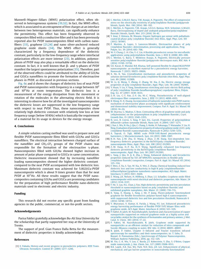
Plots of relative permittivity (commonly known as dielectricconstant) of the neat PVDF and PVDF nanocomposites measured atroom temperature in a frequency range between 102 and 106Hz areshown in Fig. 6a and b. As it can be seen in Fig. 6a, a remarkableimprovement in relative permittivity in comparison to neat PVDFis observed even when only 0.5%wt of GO/Au nanoparticles areadded to PVDF. It is worthwhile to observe that the increase of thedielectric constant values is proportional to the filler content. In
Fig. 6. Frequency dependence of dielectric constant and dielectric loss tangent (tan d) of
fact, the dielectric constant measured at 103Hz increases fromabout 5 (neat PVDF) to about 23 for 0.5GO/Au-PVDF, to about 31 for1.0GO/Au-PVDF, to about 39 for 5.0GO/Au-PVDF nanocomposites.A similar behaviour can be observed in Fig. 6b for the dielectricconstant of nanocomposite thin films with 0.5, 1.0 and 5.0 % wt. ofGO/Cu nanoparticles. In this case, at a frequency of 103Hz thedielectric constant of neat PVFD is increased to about 12 for 0.5GO/Cu-PVDF, to about 27 for 1.0GO/Cu-PVDF, to about 45 for 5.0GO/Cu-PVDF nanocomposites. The observed behaviour is consistent withwhat previously observed by He et al. on the effect of grapheneoxide on the relative permittivity of PVDF nanocomposites filmsobtained using solvent N,N-Dimethylformamide (DMF) andcosolvent comprising deionized water/DMF combination [31].
In general, an increment of relative permittivity may occur forseveral reasons. One of them is the formation of a network ofmicro-capacitors in the nanocomposite due to the presence ofnanofillers. This mechanisms has been reported by He et al. in astudy on the effect of expanded graphite nanoparticles (xGnP) onthe dielectric permittivity of PVDF nanocomposites [23]. In fact,when GO/Au and GO/Cu nanofillers are incorporated into the PVDFmatrix, they could play the role of micro-capacitors thus resultingin an overall increase of the dielectric constant of the nano-composites with respect of that of neat PVDF.
Another possible mechanisms responsible for the observedincrease of the dielectric constant in nanocomposites could be the
pure PVDF and nanoocomposites with various amount of a,c) GO/Au and b, d) GO/Cu.
P. Fakhri et al. / Synthetic Metals 220 (2016) 653–660 659
Maxwell–Wagner–Sillars (MWS) polarization effect, often ob-served in heterogeneous systems [19,32]. In fact, the MWS effect,which is associated to an entrapment of free charges at an interfacebetween two heterogeneous materials, can significantly enhancethe permittivity. This effect has been frequently observed incomposites filled with a conductive filler and it has been previouslyreported also for PVDF nanocomposites filled with carbon nano-fibers [33], graphene [21,24] and nano silver-anchored reducedgraphene oxide sheets [34]. The MWS effect is generallycharacterized by a frequency dependence of the dielectricconstant, particularly in the low-frequency range where interfacialpolarization effects are more intense [23]. In addition, polymor-phism of PVDF may also play a remarkable effect on the dielectricconstant. In fact, it is well known that b- and g-phases of PVDFmanifest the largest spontaneous polarization [35]. Therefore, partof the observed effects could be attributed to the ability of GO/Auand GO/Cu nanofillers to promote the formation of electroactivephases in PVDF, as discussed in previous sections.
Fig. 6c and d shows the changes of dielectric loss of neat PVDFand PVDF nanocomposites with frequency in a range between 102
and 106Hz at room temperature. The dielectric loss is ameasurement of the energy dissipation from the movement orrotation of the molecules in the alternating electric field. It isinteresting to observe how for all the investigated nanocompositesthe dielectric losses are suppressed in the low frequency rangewith respect to neat PVDF. Thus, these nanocomposites showrelatively high dielectric constant with relatively low loss at lowfrequency range (below 10 KHz) which is basically the requirementof a material for its usage in devices for the energy storage.
4. Conclusions
A simple solution casting method was used to prepare new andflexible PVDF nanocomposite films filled with GO/Au and GO/Cunanofillers. The electrical interaction between charged surface ofthe nanofiller and CH2-CF2 groups of the PVDF chains wasresponsible for the formation of the electroactive g-phase.Nanocomposites filled with GO/Au showed higher increase inamount of polar phase compared to GO/Cu in same concentration.Dielectric measurement showed that by increasing nanofillerloading nanocomposites showed the higher dielectric constantcompared to the neat PVDF accompanied with low dielectric loss.Maximum dielectric constant was achieved for 5.0GO/Cu-PVDFnanocomposite which is about 9 times greater than that for neatPVDF at 103Hz. All these results suggest that the PVDF nano-composites containing GO/Au and GO/Cu are promising candidatesfor the preparation of high performance flexible nano-dielectricmaterials used in electronic and electric industry.
Funding
This research did not receive any specific grant from fundingagencies in the public, commercial, or not-for-profit sectors.
Acknowledgements
Parisa Fakhri gratefully acknowledges Bu-Ali Sina University forthe scholarship that partly supported her stay at the University ofTrento.
The support of prof. Gian Franco Dalla Betta for the measure-ment of dielectric properties is kindly acknowledged.
References
[1] E. Fukada, History and recent progress in piezoelectric polymers, IEEE Trans.Ultrason. Ferroelectr. Control 47 (2000) 1277–1290.
[2] C. Merlini, G.M.d.O. Barra, T.M. Araujo, A. Pegoretti, The effect of compressivestress on the electrically resistivity of poly(vinylidene fluoride)/polypyrroleblends, Synth. Met. 196 (2014) 186–192.
[3] C. Merlini, A. Pegoretti, T.M. Araujo, S.D.A.S. Ramoa, W.H. Schreiner, G.M.d.O.Barra, Electrospinning of doped and undoped-polyaniline/poly(vinylidenefluoride) blends, Synth. Met. 213 (2016) 34–41.
[4] Y. Imai, Y. Kimura, M. Niwano, Organic hydrogen gas sensor with palladium-coated b-phase poly (vinylidene fluoride) thin films, Appl. Phys. Lett. 101(2012) 181907.
[5] P. Martins, A. Lopes, S. Lanceros-Mendez, Electroactive phases of poly(vinylidene fluoride): determination, processing and applications, Prog.Polym. Sci. 39 (2014) 683–706.
[6] W.-Y. Chang, C.-H. Chu, Y.-C. Lin, A flexible piezoelectric sensor for microfluidicapplications using polyvinylidene fluoride, Sens. J. IEEE 8 (2008) 495–500.
[7] C. Merlini, G. Barra, T. Medeiros Araujo, A. Pegoretti, Electrically pressuresensitive poly(vinylidene fluoride)/polypyrrole electrospun mats, RSC Adv. 4(2014) 15749–15758.
[8] S.K. Karan, D. Mandal, B.B. Khatua, Self-powered flexible Fe-doped RGO/PVDFnanocomposite: an excellent material for a piezoelectric energy harvester,Nanoscale 7 (2015) 10655–10666.
[9] X. He, K. Yao, Crystallization mechanism and piezoelectric properties ofsolution-derived ferroelectric poly (vinylidene fluoride) thin films, Appl. Phys.Lett. 89 (2006) 112909.
[10] W. Li, Q. Meng, Y. Zheng, Z. Zhang, W. Xia, Z. Xu, Electric energy storageproperties of poly (vinylidene fluoride), Appl. Phys. Lett. 96 (2010) 192905.
[11] Y. Huan, Y. Liu, Y. Yang, Simultaneous stretching and static electric field polingof poly (vinylidene fluoride-hexafluoropropylene) copolymer films, Polym.Eng. Sci. 47 (2007) 1630–1633.
[12] Z.-H. Liu, C.-T. Pan, Z.-Y. Ou, W.-C. Wang, Piezoelectricity of well-alignedelectrospun fiber composites, Sens. J. IEEE 13 (2013) 4098–4103.
[13] B. Wang, H.-X. Huang, Incorporation of halloysite nanotubes into PVDF matrix:nucleation of electroactive phase accompany with significant reinforcementand dimensional stability improvement, Compos. Part A: Appl. Sci. Manuf. 66(2014) 16–24.
[14] M. Sharma, G. Madras, S. Bose, Contrasting effects of graphene oxide and poly(ethylenimine) on the polymorphism in poly (vinylidene fluoride), Cryst.Growth Des. 15 (2015) 3345–3355.
[15] N. Levi, R. Czerw, S. Xing, P. Iyer, D.L. Carroll, Properties of polyvinylidenedifluoride-carbon nanotube blends, Nano Lett. 4 (2004) 1267–1271.
[16] J. Xue, L. Wu, N. Hu, J. Qiu, C. Chang, S. Atobe, H. Fukunaga, T. Watanabe, Y. Liu, H.Ning, Evaluation of piezoelectric propertyof reduced graphene oxide (rGO)–poly(vinylidene fluoride) nanocomposites, Nanoscale 4 (2012) 7250–7255.
[17] A. Toprak, O. Tigli, MEMS scale PVDF-TrFE-Based piezoelectric energyharvesters, J. Microelectromech. Syst. 24 (2015) 1989–1997.
[18] B.-H. Fan, J.-W. Zha, D. Wang, J. Zhao, Z.-M. Dang, Size-dependent low-frequency dielectric properties in the BaTiO3/poly (vinylidene fluoride)nanocomposite films, Appl. Phys. Lett. 100 (2012) 012903.
[19] Z.-M. Dang, H.-P. Xu, H.-Y. Wang, Significantly enhanced low-frequencydielectric permittivity in the BaTiO3/poly (vinylidene fluoride)nanocomposite, Appl. Phys. Lett. 90 (2007) 012901.
[20] L. Yang, J. Qiu, H. Ji, K. Zhu, J. Wang, Enhanced dielectric and ferroelectricproperties induced by TiO 2@ MWCNTs nanoparticles in flexible poly(vinylidene fluoride) composites, Compos. Part A: Appl. Sci. Manuf. 65 (2014)125–134.
[21] F. Wen, Z. Xu, S. Tan, W. Xia, X. Wei, Z. Zhang, Chemical bonding-induced lowdielectric loss and low conductivity in high-K poly (vinylidenefluoride-trifluorethylene)/graphene nanosheets nanocomposites, ACS Appl. Mater.Interfaces 5 (2013) 9411–9420.
[22] Z. Wang, J.K. Nelson, H. Hillborg, S. Zhao, L.S. Schadler, Graphene oxide fillednanocomposite with novel electrical and dielectric properties, Adv. Mater. 24(2012) 3134–3137.
[23] F. He, S. Lau, H.L. Chan, J. Fan, High dielectric permittivity and low percolationthreshold in nanocomposites based on poly (vinylidene fluoride) andexfoliated graphite nanoplates, Adv. Mater. 21 (2009) 710–715.
[24] K. Yang, X. Huang, L. Fang, J. He, P. Jiang, Fluoro-polymer functionalizedgraphene for flexible ferroelectric polymer-based high-k nanocompositeswith suppressed dielectric loss and low percolation threshold, Nanoscale 6(2014) 14740–14753.
[25] V. Bhavanasi, V. Kumar, K. Parida, J. Wang, P.S. Lee, Enhanced piezoelectricenergy harvesting performance of flexible PVDF-TrFE bilayer films withgraphene oxide, ACS Appl. Mater. Interfaces 8 (2016) 521–529.
[26] P. Fakhri, B. Jaleh, M. Nasrollahzadeh, Synthesis and characterization of coppernanoparticles supported on reduced graphene oxide as a highly active andrecyclable catalyst for the synthesis of formamides and primary amines, J. Mol.Catal. A: Chem. 383 (2014) 17–22.
[27] P. Fakhri, M. Nasrollahzadeh, B. Jaleh, Graphene oxide supported Aunanoparticles as an efficient catalyst for reduction of nitro compounds andSuzuki–Miyaura coupling in water, RSC Adv. 4 (2014) 48691–48697.
[28] B. Jaleh, P. Fakhri, Chapter 5—Infrared and Fourier transform infraredspectroscopy for nanofillers and their nanocomposites, in: T. Sabu, D.Rouxel, D. Ponnamma (Eds.), Spectroscopy of Polymer Nanocomposites,William Andrew Publishing, 2016, pp. 112–129.
[29] M. Yin, C.-K. Wu, Y. Lou, C. Burda, J.T. Koberstein, Y. Zhu, S. O’Brien, Copperoxide nanocrystals, J. Am. Chem. Soc. 127 (2005) 9506–9511.
[30] R.K. Layek, A.K. Das, M.J. Park, N.H. Kim, J.H. Lee, Enhancement of physical,mechanical, and gas barrier properties in noncovalently functionalized
660 P. Fakhri et al. / Synthetic Metals 220 (2016) 653–660
graphene oxide/poly (vinylidene fluoride) composites, Carbon 81 (2015) 329–338.
[31] N. An, S. Liu, C. Fang, R. Yu, X. Zhou, Y. Cheng, Preparation and properties ofb-phase graphene oxide/PVDF composite films, J. Appl. Polym. Sci. 132 (2015) (n/a-n/a).
[32] F. Kremer, A. Schönhals, Broadband Dielectric Spectroscopy, Springer-Verlag,2003.
[33] L. Sun, B. Li, Y. Zhao, G. Mitchell, W. Zhong, Structure-induced high dielectricconstant and low loss of CNF/PVDF composites with heterogeneous CNFdistribution, Nanotechnology 21 (2010) 305702.
[34] S. Wageh, L. He, A.A. Al-Ghamdi, Y. Al-Turki, S. Tjong, Nano silver-anchoredreduced graphene oxide sheets for enhanced dielectric performance ofpolymer nanocomposites, RSC Adv. 4 (2014) 28426–28431.
[35] A. Roy, B. Dutta, S. Bhattacharya, Electroactive phase nucleation and non-isothermal crystallization kinetics study in [DEMM][TFSI] ionic liquidincorporated P(VDF-HFP) co-polymer membranes, J. Mater. Sci. 51 (2016)7814–7830.