Embed Size (px)
Citation preview
Installation Guide for
Buried Precast
Three-Sided Arch Culverts Three-Tangent Top Culverts
and Three-Sided Box Culverts
SPECS 1106 Second Street #636
Encinitas, CA 92024 (858) 790-1890 or (858) 790-1445
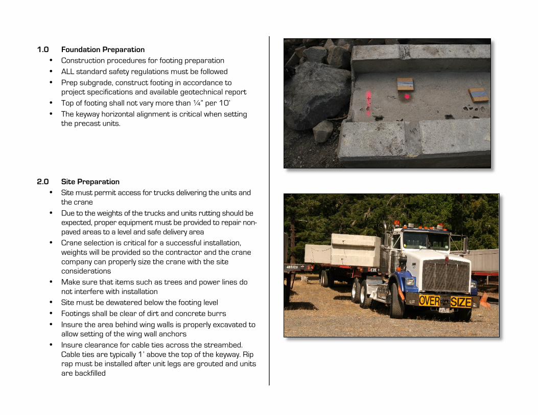
1.0 Foundation Preparation
• Construction procedures for footing preparation • ALL standard safety regulations must be followed • Prep subgrade, construct footing in accordance to
project specifications and available geotechnical report • Top of footing shall not vary more than ¼” per 10’ • The keyway horizontal alignment is critical when setting
the precast units.
2.0 Site Preparation
• Site must permit access for trucks delivering the units and the crane
• Due to the weights of the trucks and units rutting should be expected, proper equipment must be provided to repair non-paved areas to a level and safe delivery area
• Crane selection is critical for a successful installation, weights will be provided so the contractor and the crane company can properly size the crane with the site considerations
• Make sure that items such as trees and power lines do not interfere with installation
• Site must be dewatered below the footing level • Footings shall be clear of dirt and concrete burrs • Insure the area behind wing walls is properly excavated to
allow setting of the wing wall anchors • Insure clearance for cable ties across the streambed.
Cable ties are typically 1’ above the top of the keyway. Rip rap must be installed after unit legs are grouted and units are backfilled
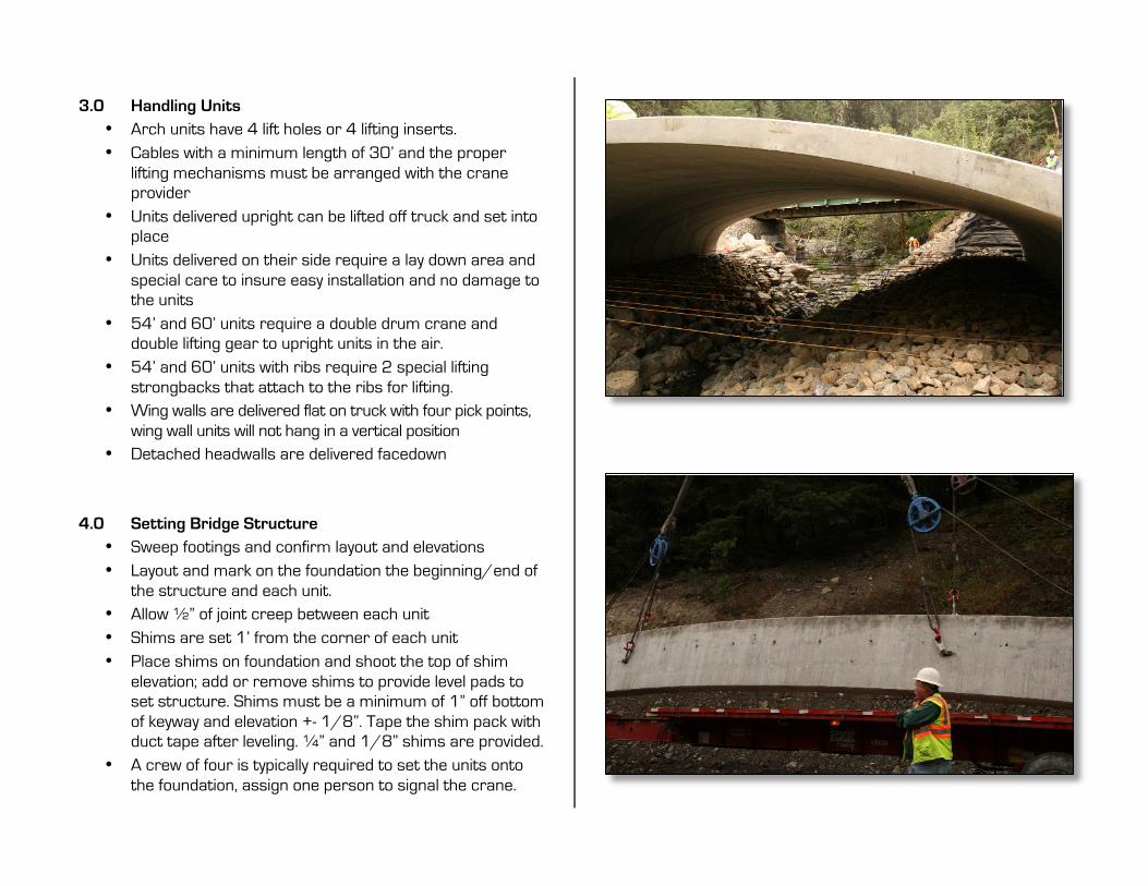
3.0 Handling Units
• Arch units have 4 lift holes or 4 lifting inserts. • Cables with a minimum length of 30’ and the proper
lifting mechanisms must be arranged with the crane provider
• Units delivered upright can be lifted off truck and set into place
• Units delivered on their side require a lay down area and special care to insure easy installation and no damage to the units
• 54’ and 60’ units require a double drum crane and double lifting gear to upright units in the air.
• 54’ and 60’ units with ribs require 2 special lifting strongbacks that attach to the ribs for lifting.
• Wing walls are delivered flat on truck with four pick points, wing wall units will not hang in a vertical position
• Detached headwalls are delivered facedown
4.0 Setting Bridge Structure • Sweep footings and confirm layout and elevations • Layout and mark on the foundation the beginning/end of
the structure and each unit. • Allow ½” of joint creep between each unit • Shims are set 1’ from the corner of each unit • Place shims on foundation and shoot the top of shim
elevation; add or remove shims to provide level pads to set structure. Shims must be a minimum of 1” off bottom of keyway and elevation +- 1/8”. Tape the shim pack with duct tape after leveling. ¼” and 1/8” shims are provided.
• A crew of four is typically required to set the units onto the foundation, assign one person to signal the crane.

• 54’ and 60’ units with ribs require 2 people and a backhoe to lift and install each strongback to the unit. Strongbacks weigh 400 lbs each.
• The first unit is critical for the proper alignment of the structure
• Spans exceeding 24’ are shipped and installed with horizontal cable ties
• NEVER have persons under the unit until it is securely placed onto footing
• 54’ and 60’ end units with headwall must be supported in the center by an 8x8 supports, dunnage and hydraulic jack.
5.0 Setting Wing Walls
• Check the back of foundation for proper clearance at the bottom and back of wing wall for the wing wall anchor
• Loosely fasten connection plates (large holes on the plate are attached to wing wall side
• Before backfilling wing walls install drainage pipes as shown on the plans
6.0 Setting Headwalls
• Each headwall unit is matched and marked for specific placement on bridge unit
• Utilize spud bar to align bolt holes from headwall to bridge unit
• Thread nuts as tight as snug as possible, follow grouting procedure, waterproofing outlined below
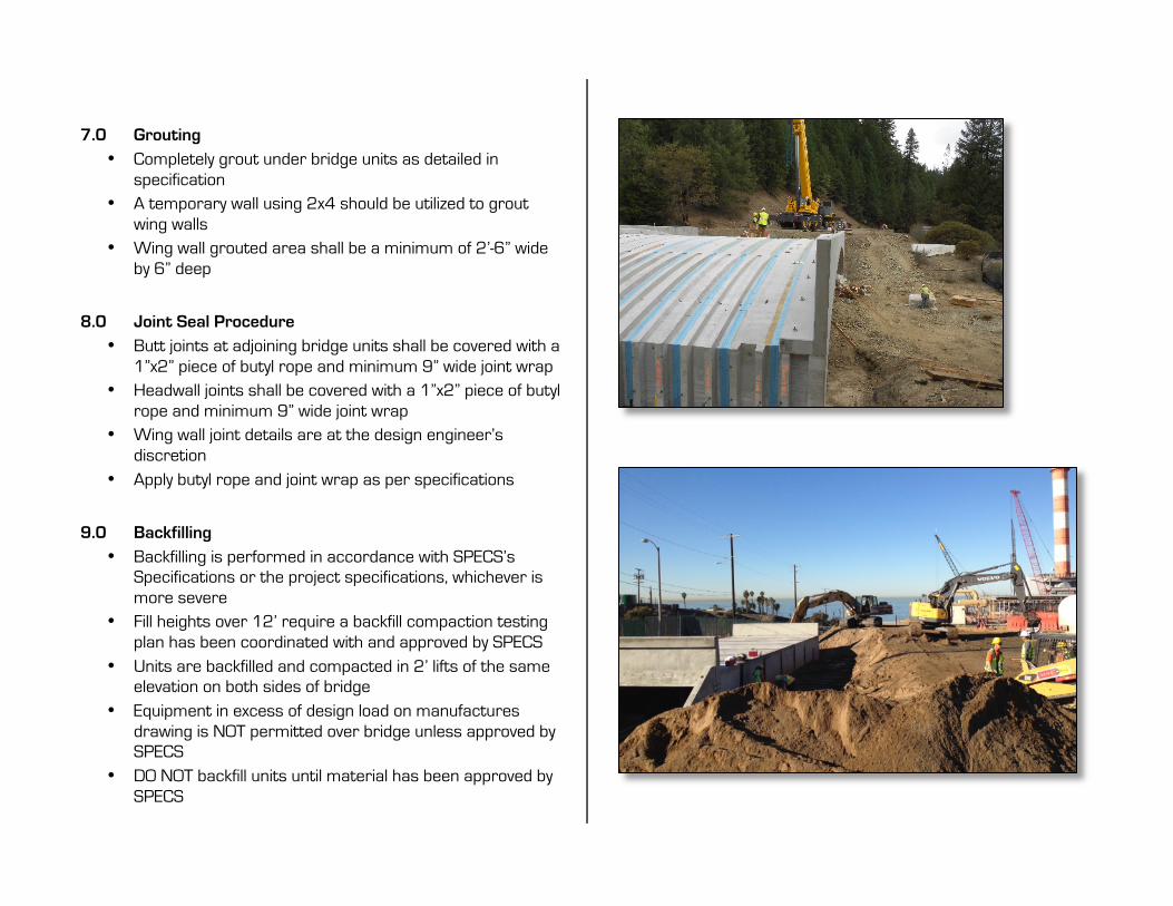
7.0 Grouting
• Completely grout under bridge units as detailed in specification
• A temporary wall using 2x4 should be utilized to grout wing walls
• Wing wall grouted area shall be a minimum of 2’-6” wide by 6” deep
8.0 Joint Seal Procedure
• Butt joints at adjoining bridge units shall be covered with a 1”x2” piece of butyl rope and minimum 9” wide joint wrap
• Headwall joints shall be covered with a 1”x2” piece of butyl rope and minimum 9” wide joint wrap
• Wing wall joint details are at the design engineer’s discretion
• Apply butyl rope and joint wrap as per specifications
9.0 Backfilling
• Backfilling is performed in accordance with SPECS’s Specifications or the project specifications, whichever is more severe
• Fill heights over 12’ require a backfill compaction testing plan has been coordinated with and approved by SPECS
• Units are backfilled and compacted in 2’ lifts of the same elevation on both sides of bridge
• Equipment in excess of design load on manufactures drawing is NOT permitted over bridge unless approved by SPECS
• DO NOT backfill units until material has been approved by SPECS

10.0 Jobsite Tools
• Minimum of (4) 60” pry bars • 48” spirit level • 8’ straight edge • Transit level • (2) 10’ ladders • Chalk line and marking paint • Large box end / Crescent Wrenches for wing wall
hardware • 2-4 electric impact drivers and deep sockets for 54’ and
60’ strongback installation. • (2) “come-alongs” • 1” drill bit and hammer drill for Hilti Kwik Bolt 3 • 1 ½” Deep Impact Socket • 1 5/8” Deep Impact Socket • 1 ½” box end/open end • 1 5/8” box end/open end • 2 each 2” box end/open end or 1, 2” box end/open end
and large Crescent Wrench 11.0 Jobsite Materials
• (16 per unit) of 6” x 6” x ¼” and 1/8”) Masonite shims • Joint wrap and butyl rope • Joint primer • Lift hole plugs • 2 sets of paint rollers and pans to place primer