Embed Size (px)
Citation preview
Installation instructions ClassicController
CR0033
7390
928
/ 00
06 /
2014
UK
ClassicController CR0033
2
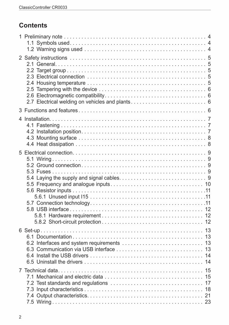
Contents1 Preliminary note � � � � � � � � � � � � � � � � � � � � � � � � � � � � � � � � � � � � � � � � � � � � � � � � � 4
1�1 Symbols used� � � � � � � � � � � � � � � � � � � � � � � � � � � � � � � � � � � � � � � � � � � � � � � 41�2 Warning signs used � � � � � � � � � � � � � � � � � � � � � � � � � � � � � � � � � � � � � � � � � � 4
2 Safety instructions � � � � � � � � � � � � � � � � � � � � � � � � � � � � � � � � � � � � � � � � � � � � � � � 52�1 General� � � � � � � � � � � � � � � � � � � � � � � � � � � � � � � � � � � � � � � � � � � � � � � � � � � � 52�2 Target group � � � � � � � � � � � � � � � � � � � � � � � � � � � � � � � � � � � � � � � � � � � � � � � � 52�3 Electrical connection � � � � � � � � � � � � � � � � � � � � � � � � � � � � � � � � � � � � � � � � � 52�4 Housing temperature � � � � � � � � � � � � � � � � � � � � � � � � � � � � � � � � � � � � � � � � � 52�5 Tampering with the device � � � � � � � � � � � � � � � � � � � � � � � � � � � � � � � � � � � � � 62�6 Electromagnetic compatibility� � � � � � � � � � � � � � � � � � � � � � � � � � � � � � � � � � � 62�7 Electrical welding on vehicles and plants � � � � � � � � � � � � � � � � � � � � � � � � � � 6
3 Functions and features � � � � � � � � � � � � � � � � � � � � � � � � � � � � � � � � � � � � � � � � � � � � 64 Installation� � � � � � � � � � � � � � � � � � � � � � � � � � � � � � � � � � � � � � � � � � � � � � � � � � � � � � 7
4�1 Fastening � � � � � � � � � � � � � � � � � � � � � � � � � � � � � � � � � � � � � � � � � � � � � � � � � � 74�2 Installation position� � � � � � � � � � � � � � � � � � � � � � � � � � � � � � � � � � � � � � � � � � � 74�3 Mounting surface � � � � � � � � � � � � � � � � � � � � � � � � � � � � � � � � � � � � � � � � � � � � 84�4 Heat dissipation � � � � � � � � � � � � � � � � � � � � � � � � � � � � � � � � � � � � � � � � � � � � � 8
5 Electrical connection� � � � � � � � � � � � � � � � � � � � � � � � � � � � � � � � � � � � � � � � � � � � � � 95�1 Wiring � � � � � � � � � � � � � � � � � � � � � � � � � � � � � � � � � � � � � � � � � � � � � � � � � � � � � 95�2 Ground connection � � � � � � � � � � � � � � � � � � � � � � � � � � � � � � � � � � � � � � � � � � � 95�3 Fuses � � � � � � � � � � � � � � � � � � � � � � � � � � � � � � � � � � � � � � � � � � � � � � � � � � � � � 95�4 Laying the supply and signal cables� � � � � � � � � � � � � � � � � � � � � � � � � � � � � � 95�5 Frequency and analogue inputs � � � � � � � � � � � � � � � � � � � � � � � � � � � � � � � � 105�6 Resistor inputs � � � � � � � � � � � � � � � � � � � � � � � � � � � � � � � � � � � � � � � � � � � � � �11
5�6�1 Unused input I15 � � � � � � � � � � � � � � � � � � � � � � � � � � � � � � � � � � � � � � � �115�7 Connection technology� � � � � � � � � � � � � � � � � � � � � � � � � � � � � � � � � � � � � � � �115�8 USB interface � � � � � � � � � � � � � � � � � � � � � � � � � � � � � � � � � � � � � � � � � � � � � � 12
5�8�1 Hardware requirement � � � � � � � � � � � � � � � � � � � � � � � � � � � � � � � � � � � 125�8�2 Short-circuit protection � � � � � � � � � � � � � � � � � � � � � � � � � � � � � � � � � � � 12
6 Set-up � � � � � � � � � � � � � � � � � � � � � � � � � � � � � � � � � � � � � � � � � � � � � � � � � � � � � � � � 136�1 Documentation � � � � � � � � � � � � � � � � � � � � � � � � � � � � � � � � � � � � � � � � � � � � � 136�2 Interfaces and system requirements � � � � � � � � � � � � � � � � � � � � � � � � � � � � 136�3 Communication via USB interface � � � � � � � � � � � � � � � � � � � � � � � � � � � � � � 136�4 Install the USB drivers � � � � � � � � � � � � � � � � � � � � � � � � � � � � � � � � � � � � � � � 146�5 Uninstall the drivers � � � � � � � � � � � � � � � � � � � � � � � � � � � � � � � � � � � � � � � � � 14
7 Technical data� � � � � � � � � � � � � � � � � � � � � � � � � � � � � � � � � � � � � � � � � � � � � � � � � � 157�1 Mechanical and electric data � � � � � � � � � � � � � � � � � � � � � � � � � � � � � � � � � � 157�2 Test standards and regulations � � � � � � � � � � � � � � � � � � � � � � � � � � � � � � � � 177�3 Input characteristics � � � � � � � � � � � � � � � � � � � � � � � � � � � � � � � � � � � � � � � � � 187�4 Output characteristics� � � � � � � � � � � � � � � � � � � � � � � � � � � � � � � � � � � � � � � � 217�5 Wiring � � � � � � � � � � � � � � � � � � � � � � � � � � � � � � � � � � � � � � � � � � � � � � � � � � � � 23
UK
ClassicController CR0033
3
8 Maintenance, repair and disposal� � � � � � � � � � � � � � � � � � � � � � � � � � � � � � � � � � � 249 Approvals/standards � � � � � � � � � � � � � � � � � � � � � � � � � � � � � � � � � � � � � � � � � � � � � 24
This document is the original instructions� All trademarks and company names are subject to the copyright of the respective companies�
ClassicController CR0033
4
1 Preliminary noteThis document applies to devices of the type "ClassicController" (art� no�: CR0033)� These instructions are an integral part of the device�This document is intended for specialists� These specialists are people who are qualified by their appropriate training and their experience to see risks and to avoid possible hazards that may be caused during operation or maintenance of the device� The document contains information about the correct handling of the device�Read this document before use to familiarise yourself with operating conditions, installation and operation� Keep this document during the entire duration of use of the device�Adhere to the safety instructions�
1.1 Symbols used► Instruction> Reaction, result[…] Designation of keys, buttons or indications→ Cross-reference
Important note Non-compliance can result in malfunction or interference�Information Supplementary note
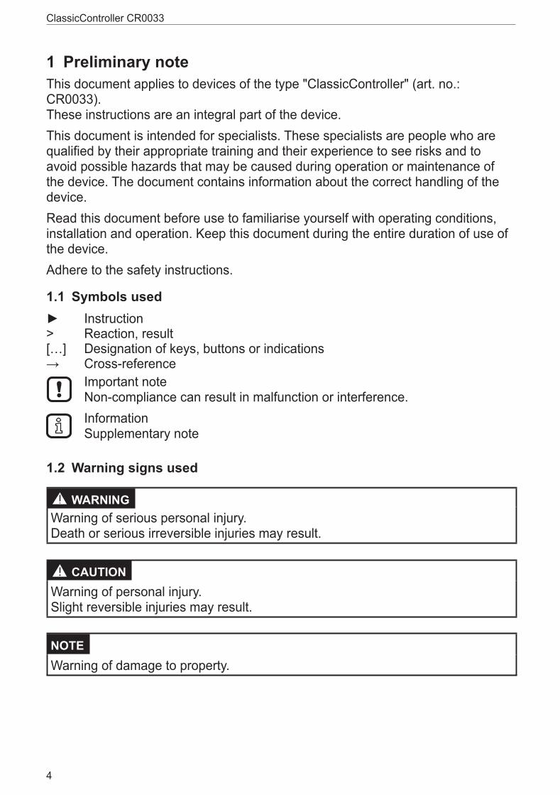
1.2 Warning signs used
WARNINGWarning of serious personal injury� Death or serious irreversible injuries may result�
CAUTION Warning of personal injury� Slight reversible injuries may result�
NOTE Warning of damage to property�
UK
ClassicController CR0033
5
2 Safety instructions2.1 GeneralThese instructions are an integral part of the device� They contain texts and figures concerning the correct handling of the device and must be read before installation or use�Observe the operating instructions� Non-observance of the instructions, operation which is not in accordance with use as prescribed below, wrong installation or incorrect handling can seriously affect the safety of operators and machinery�
2.2 Target groupThese instructions are intended for authorised persons according to the EMC and low-voltage directives� The device must only be installed, connected and put into operation by a qualified electrician�
2.3 Electrical connectionDisconnect the device externally before handling it� If necessary, also disconnect any independently supplied output load circuits�If the device is not supplied by the mobile on-board system (12/24 V battery operation), it must be ensured that the external voltage is generated and supplied according to the criteria for safety extra-low voltage (SELV) as this voltage is supplied without further measures to the connected controller, the sensors and the actuators�The wiring of all signals in connection with the SELV circuit of the device must also comply with the SELV criteria (safety extra-low voltage, safe electrical isolation from other electric circuits)�If the supplied SELV voltage is externally grounded (SELV becomes PELV), the responsibility lies with the user and the respective national installation regulations must be complied with� All statements in this document refer to the device the SELV voltage of which is not grounded�The connection terminals may only be supplied with the signals indicated in the technical data and/or on the device label and only the approved accessories of ifm electronic may be connected�
2.4 Housing temperatureAs described in the technical specifications below the device can be operated in a wide ambient temperature range� Because of the additional internal heating the housing walls can have high perceptible temperatures when touched in hot environments�

ClassicController CR0033
6
2.5 Tampering with the deviceIn case of malfunctions or uncertainties please contact the manufacturer� Any tampering with the device can seriously affect the safety of operators and machinery� This is not permitted and leads to the exclusion of any liability and warranty claims�
2.6 Electromagnetic compatibilityThis is a class A product� It can cause radio interference in domestic areas� In this case the operator is requested to take appropriate measures�
2.7 Electrical welding on vehicles and plantsWelding work on the chassis frame must only be carried out by qualified persons�Remove and cover the plus and minus terminals of the batteries� Disconnect all contacts of the controller from the on-board system prior to welding on the vehicle or plant� Connect the earth terminal of the welding device directly to the part to be welded�Do not touch the controller or electric cables with the welding electrode or the earth terminal of the welding device�Protect the controller against weld slag�
3 Functions and featuresThe freely programmable controllers of the "ClassicController" series are rated for use under difficult conditions (e�g� extended temperature range, strong vibration, intensive EMC interference)�They are suited for direct installation in machines in mobile and robust applications� Integrated hardware and software functions (operating system) offer high protection for the machine�The controllers can be used as CANopen master�
WARNINGThe "ClassicController" series is not approved for safety tasks in the field of safety of persons�
WARNINGThe user is responsible for the safe function of the application programswhich he created himself� If necessary, he must additionally carry out an approval test by corresponding supervisory and test organisations according to the national regulations�
UK
ClassicController CR0033
7
4 Installation4.1 Fastening
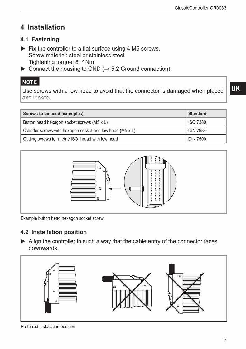
► Fix the controller to a flat surface using 4 M5 screws� Screw material: steel or stainless steel Tightening torque: 8 ±2 Nm
► Connect the housing to GND (→ 5.2 Ground connection).
NOTE Use screws with a low head to avoid that the connector is damaged when placed and locked�
Screws to be used (examples) Standard
Button head hexagon socket screws (M5 x L) ISO 7380
Cylinder screws with hexagon socket and low head (M5 x L) DIN 7984
Cutting screws for metric ISO thread with low head DIN 7500
Example button head hexagon socket screw
4.2 Installation position ► Align the controller in such a way that the cable entry of the connector faces downwards�
Preferred installation position
ClassicController CR0033
8
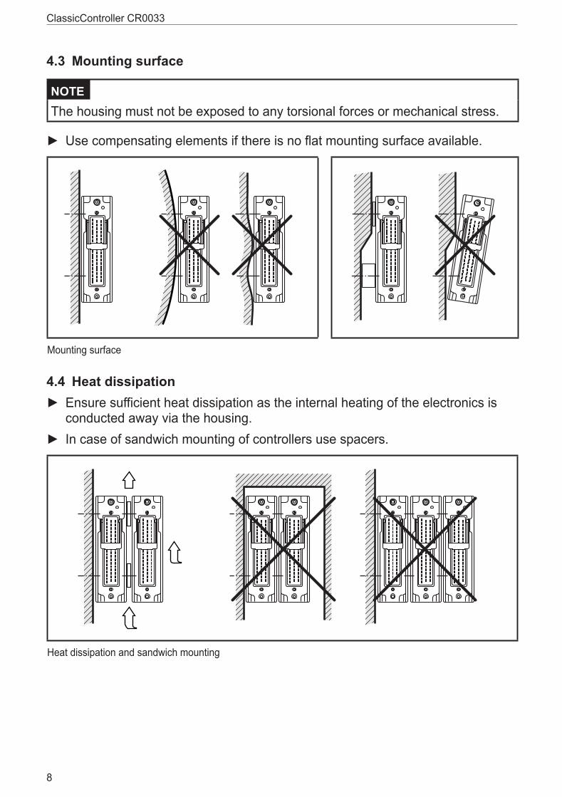
4.3 Mounting surface
NOTE The housing must not be exposed to any torsional forces or mechanical stress�
► Use compensating elements if there is no flat mounting surface available�
Mounting surface
4.4 Heat dissipation ► Ensure sufficient heat dissipation as the internal heating of the electronics is conducted away via the housing�
► In case of sandwich mounting of controllers use spacers�
Heat dissipation and sandwich mounting
UK
ClassicController CR0033
9
5 Electrical connection5.1 WiringWiring (→ 7 Technical data)
Only connect the connector pins as shown in the pin layout� Unspecified connector pins remain unconnected�
► Connect all supply cables and GND terminals�
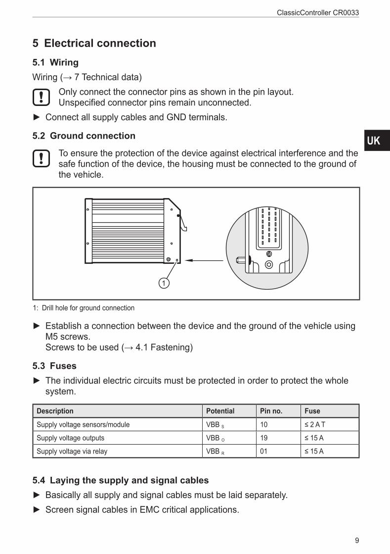
5.2 Ground connection
To ensure the protection of the device against electrical interference and the safe function of the device, the housing must be connected to the ground of the vehicle�
1: Drill hole for ground connection
► Establish a connection between the device and the ground of the vehicle using M5 screws� Screws to be used (→ 4.1 Fastening)
5.3 Fuses ► The individual electric circuits must be protected in order to protect the whole system�
Description Potential Pin no. Fuse
Supply voltage sensors/module VBB S 10 ≤ 2 A T
Supply voltage outputs VBB O 19 ≤ 15 A
Supply voltage via relay VBB R 01 ≤ 15 A
5.4 Laying the supply and signal cables ► Basically all supply and signal cables must be laid separately� ► Screen signal cables in EMC critical applications�
ClassicController CR0033
10
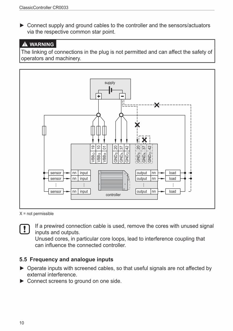
► Connect supply and ground cables to the controller and the sensors/actuators via the respective common star point�
WARNINGThe linking of connections in the plug is not permitted and can affect the safety of operators and machinery�
������
������ ��
������ ��
������ ��
����������
���
���
���
���
���
��
��
��
��
���
��
��
�������
�������
�������������
������
����������
����
����
��
��
��
���
��
��
X = not permissible
If a prewired connection cable is used, remove the cores with unused signal inputs and outputs� Unused cores, in particular core loops, lead to interference coupling that can influence the connected controller�
5.5 Frequency and analogue inputs ► Operate inputs with screened cables, so that useful signals are not affected by external interference�
► Connect screens to ground on one side�
UK
ClassicController CR0033
11
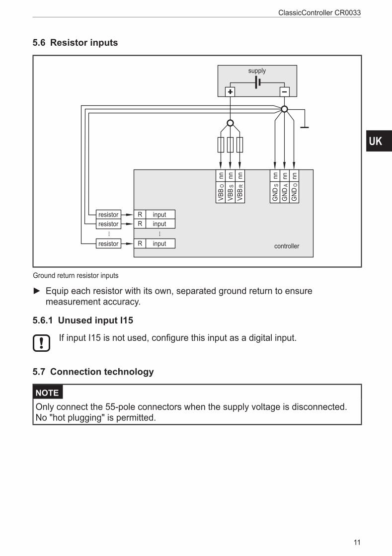
5.6 Resistor inputs
supply
controller
VBB
Onn
VBB
Snn
VBB
Rnn
GND
Snn
GND
Ann
GND
Onn
inputR
inputR
resistor
resistor
inputRresistor
Ground return resistor inputs
► Equip each resistor with its own, separated ground return to ensure measurement accuracy�
5.6.1 Unused input I15
If input I15 is not used, configure this input as a digital input�
5.7 Connection technology
NOTE Only connect the 55-pole connectors when the supply voltage is disconnected� No "hot plugging" is permitted�
ClassicController CR0033
12
5.8 USB interface
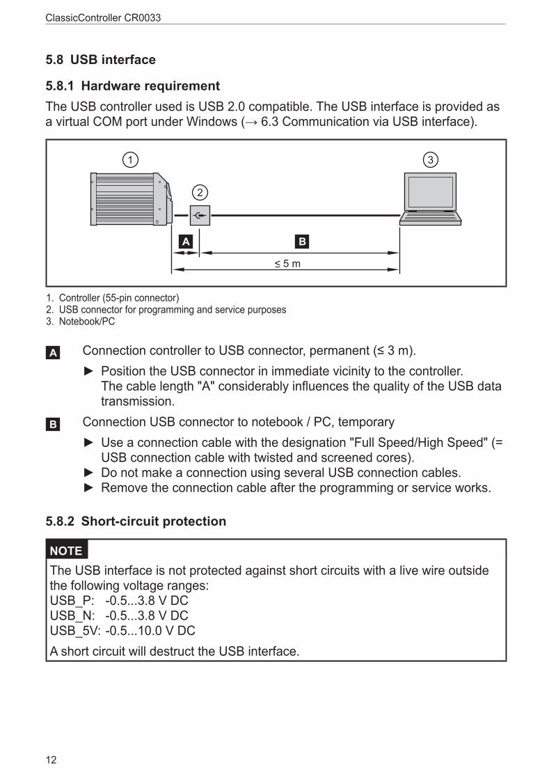
5.8.1 Hardware requirementThe USB controller used is USB 2�0 compatible� The USB interface is provided as a virtual COM port under Windows (→ 6.3 Communication via USB interface).
�
�
�
� �
���
1� Controller (55-pin connector)2� USB connector for programming and service purposes3� Notebook/PC
�
�
�
� �
���
Connection controller to USB connector, permanent (≤ 3 m). ► Position the USB connector in immediate vicinity to the controller� The cable length "A" considerably influences the quality of the USB data transmission�
�
�
�
� �
���
Connection USB connector to notebook / PC, temporary ► Use a connection cable with the designation "Full Speed/High Speed" (= USB connection cable with twisted and screened cores)�
► Do not make a connection using several USB connection cables� ► Remove the connection cable after the programming or service works�
5.8.2 Short-circuit protection
NOTE The USB interface is not protected against short circuits with a live wire outside the following voltage ranges:USB_P: -0�5���3�8 V DC USB_N: -0�5���3�8 V DC USB_5V: -0�5���10�0 V DCA short circuit will destruct the USB interface�

UK
ClassicController CR0033
13
6 Set-up6.1 DocumentationThe user can easily create the application program by means of the IEC 61131-3 compliant programming system CODESYS 2�3� In addition to the programming system CODESYS, the following documents are required for programming and commissioning of the controller:
● System manual CR0033 (alternatively CODESYS 2�3 online help)
● Manual on PLC programming with CODESYS 2�3 (alternatively CODESYS 2�3 online help)
The system manual CR0033 is available for download on the internet: www.ifm.com → Data sheet search → CR0033 → Operating instructions The manual on PLC programming with CODESYS 2�3 and the online help are automatically installed on the PC upon installation of the CODESYS package from the ecomatmobile DVD�As an alternative, the CODESYS package can be downloaded from the internet: www.ifm.com → Service → Download → Systems for mobile machines**) Download area with registration
6.2 Interfaces and system requirementsCommunication is possible via all interfaces of the controller�
System requirement for RS-232 and CAN: Microsoft Windows XP SP1 or higherSystem requirement for USB: Microsoft Windows XP SP2, Windows 7
6.3 Communication via USB interface
Note in general: ● The controller can be connected to any USB interface� The number of
the COM port does not change� ● Only connect one controller for programming to the PC� ● Special USB and COM port drivers are required�
ClassicController CR0033
14
6.4 Install the USB driversThe driver provides a "virtual COM port", i�e� another artificial serial interface, on the PC�The driver file "USB CR0032 setup vxxxx�exe" is made available on the ecomatmobile DVD�As an alternative, the driver is also available on the internet� www.ifm.com → Service → Download → Systems for mobile machines**) Download area with registration
Changes to the system settings of the PC require extended user rights� Contact your system administrator�Installation under Windows 7 will be described in the following� In other Windows versions there may be different menu names or structures�
► Start the driver file "USB CR0032 setup vxxxx�exe" and follow the setup instructions�
> The driver files and a documentation will be copied to the following directory: C:\Program Files (x86)\ifm electronic\USB_Driver_R360�
► Reboot the PC� ► Connect the controller to a free USB port ► Carry out the driver installation according to the "Installation_Guide"� The document "Installation_Guide�pdf" can be found in the following directory: C:\Program Files (x86)\ifm electronic\USB_Driver_R360\WHQL_Certified_Driver\Documentation\Installation_Guide�pdf
The driver to be installed can be found in the following directory: C:\Program Files (x86)\ifm electronic\USB_Driver_R360\WHQL_Certified_Driver\
6.5 Uninstall the drivers
If a driver is to be updated, the installed drivers have to be uninstalled first�
► Uninstall the drivers according to the "Installation_Guide" (chapter 4)� The document "Installation_Guide�pdf" can be found in the following directory: C:\Program Files (x86)\ifm electronic\USB_Driver_R360\WHQL_Certified_Driver\Documentation\Installation_Guide�pdf
UK
ClassicController CR0033
15
7 Technical data7.1 Mechanical and electric data
Control systems
ifm electronic gmbh ● Friedrichstraße 1 ● 45128 Essen We reserve the right to make technical alterations without prior notice! 06.06.2014CR0033 / page 1
CR0033
153
43LED
226 ± 1
200,5 ± 15,5
25,5
80 ± 1
15
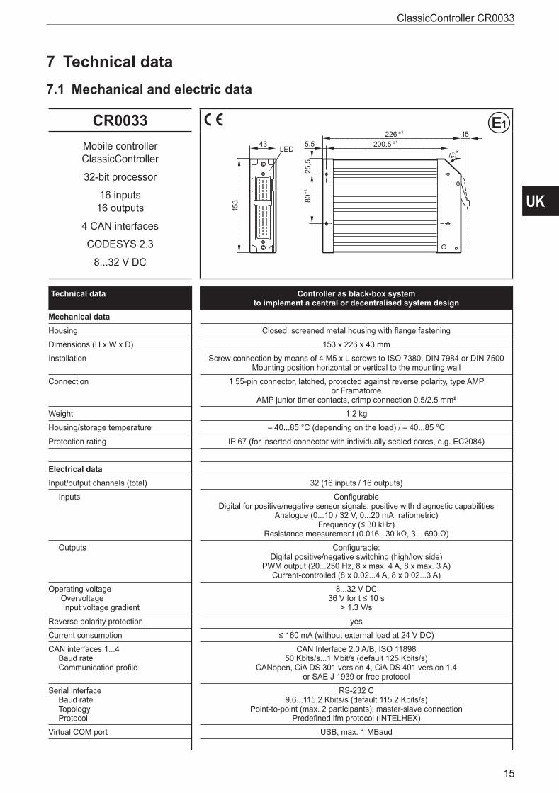
45°Mobile controllerClassicController
32-bit processor
16 inputs16 outputs
4 CAN interfaces
CODESYS 2.3
8...32 V DC
Technical data Controller as black-box systemto implement a central or decentralised system design
Mechanical dataHousing Closed, screened metal housing with ange fastening
Dimensions (H x W x D) 153 x 226 x 43 mm
Installation Screw connection by means of 4 M5 x L screws to ISO 7380, DIN 7984 or DIN 7500 Mounting position horizontal or vertical to the mounting wall
Connection 1 55-pin connector, latched, protected against reverse polarity, type AMPor Framatome
AMP junior timer contacts, crimp connection 0.5/2.5 mm²
Weight 1.2 kg
Housing/storage temperature – 40...85 °C (depending on the load) / – 40...85 °C
Protection rating IP 67 (for inserted connector with individually sealed cores, e.g. EC2084)
Electrical dataInput/output channels (total) 32 (16 inputs / 16 outputs)
Inputs Con gurableDigital for positive/negative sensor signals, positive with diagnostic capabilities
Analogue (0...10 / 32 V, 0...20 mA, ratiometric)Frequency (≤ 30 kHz)
Resistance measurement (0.016...30 kΩ, 3... 690 Ω)
Outputs Con gurable:Digital positive/negative switching (high/low side)
PWM output (20...250 Hz, 8 x max. 4 A, 8 x max. 3 A)Current-controlled (8 x 0.02...4 A, 8 x 0.02...3 A)
Operating voltage Overvoltage Input voltage gradient
8...32 V DC36 V for t ≤ 10 s
> 1.3 V/s
Reverse polarity protection yes
Current consumption ≤ 160 mA (without external load at 24 V DC)
CAN interfaces 1...4 Baud rate Communication pro le
CAN Interface 2.0 A/B, ISO 1189850 Kbits/s...1 Mbit/s (default 125 Kbits/s)
CANopen, CiA DS 301 version 4, CiA DS 401 version 1.4or SAE J 1939 or free protocol
Serial interface Baud rate Topology Protocol
RS-232 C9.6...115.2 Kbits/s (default 115.2 Kbits/s)
Point-to-point (max. 2 participants); master-slave connectionPrede ned ifm protocol (INTELHEX)
Virtual COM port USB, max. 1 MBaud
ClassicController CR0033
16
ifm electronic gmbh ● Friedrichstraße 1 ● 45128 Essen We reserve the right to make technical alterations without prior notice! 06.06.2014CR0033 / page 2
CR0033 Technical data
Control systems
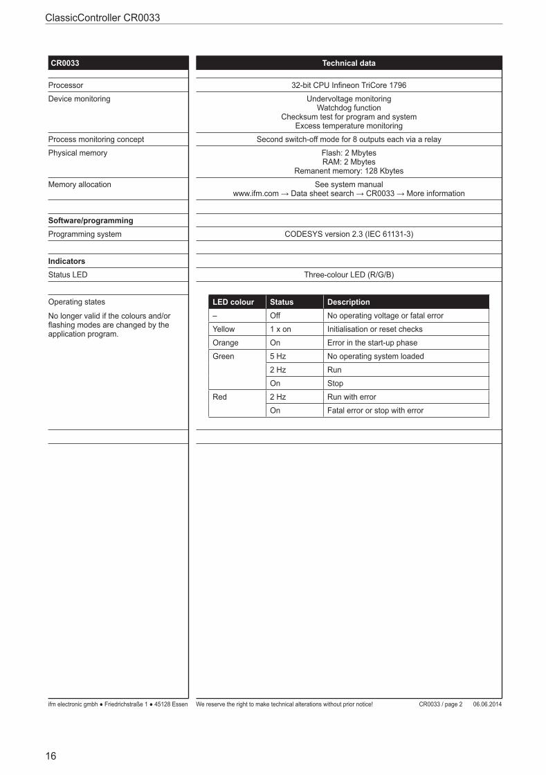
Processor 32-bit CPU In neon TriCore 1796
Device monitoring Undervoltage monitoringWatchdog function
Checksum test for program and systemExcess temperature monitoring
Process monitoring concept Second switch-off mode for 8 outputs each via a relay
Physical memory Flash: 2 MbytesRAM: 2 Mbytes
Remanent memory: 128 Kbytes
Memory allocation See system manualwww.ifm.com → Data sheet search → CR0033 → More information
Software/programmingProgramming system CODESYS version 2.3 (IEC 61131-3)
IndicatorsStatus LED Three-colour LED (R/G/B)
Operating states
No longer valid if the colours and/or ashing modes are changed by the application program.
LED colour Status Description– Off No operating voltage or fatal error
Yellow 1 x on Initialisation or reset checks
Orange On Error in the start-up phase
Green 5 Hz No operating system loaded
2 Hz Run
On Stop
Red 2 Hz Run with error
On Fatal error or stop with error
UK
ClassicController CR0033
17
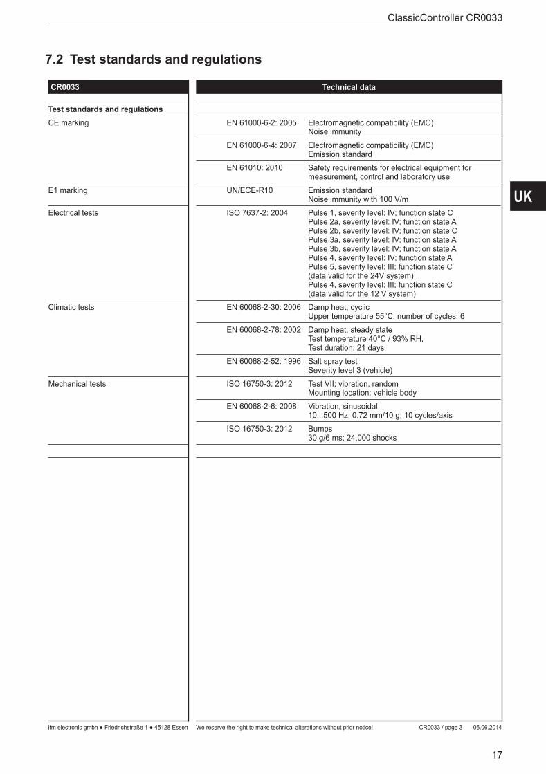
7.2 Test standards and regulations
ifm electronic gmbh ● Friedrichstraße 1 ● 45128 Essen We reserve the right to make technical alterations without prior notice! 06.06.2014CR0033 / page 3
CR0033 Technical data
Control systems
Test standards and regulationsCE marking EN 61000-6-2: 2005 Electromagnetic compatibility (EMC)
Noise immunity
EN 61000-6-4: 2007 Electromagnetic compatibility (EMC)Emission standard
EN 61010: 2010 Safety requirements for electrical equipment for measurement, control and laboratory use
E1 marking UN/ECE-R10 Emission standardNoise immunity with 100 V/m
Electrical tests ISO 7637-2: 2004 Pulse 1, severity level: IV; function state CPulse 2a, severity level: IV; function state APulse 2b, severity level: IV; function state CPulse 3a, severity level: IV; function state APulse 3b, severity level: IV; function state APulse 4, severity level: IV; function state APulse 5, severity level: III; function state C(data valid for the 24V system)Pulse 4, severity level: III; function state C(data valid for the 12 V system)
Climatic tests EN 60068-2-30: 2006 Damp heat, cyclicUpper temperature 55°C, number of cycles: 6
EN 60068-2-78: 2002 Damp heat, steady stateTest temperature 40°C / 93% RH,Test duration: 21 days
EN 60068-2-52: 1996 Salt spray testSeverity level 3 (vehicle)
Mechanical tests ISO 16750-3: 2012 Test VII; vibration, randomMounting location: vehicle body
EN 60068-2-6: 2008 Vibration, sinusoidal10...500 Hz; 0.72 mm/10 g; 10 cycles/axis
ISO 16750-3: 2012 Bumps30 g/6 ms; 24,000 shocks
ClassicController CR0033
18
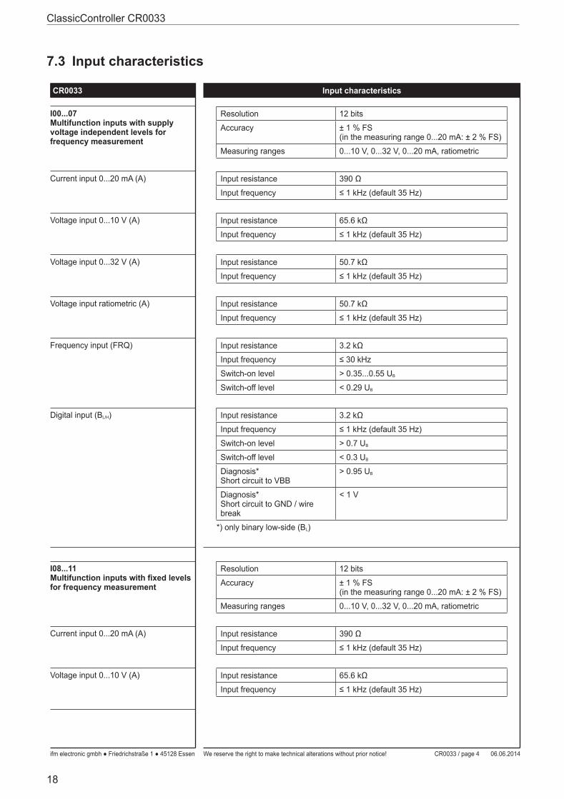
7.3 Input characteristics
ifm electronic gmbh ● Friedrichstraße 1 ● 45128 Essen We reserve the right to make technical alterations without prior notice! 06.06.2014CR0033 / page 4
CR0033 Input characteristics
Control systems
I00...07Multifunction inputs with supply voltage independent levels for frequency measurement
Resolution 12 bits
Accuracy ± 1 % FS(in the measuring range 0...20 mA: ± 2 % FS)
Measuring ranges 0...10 V, 0...32 V, 0...20 mA, ratiometric
Current input 0...20 mA (A) Input resistance 390 Ω
Input frequency ≤ 1 kHz (default 35 Hz)
Voltage input 0...10 V (A) Input resistance 65.6 kΩ
Input frequency ≤ 1 kHz (default 35 Hz)
Voltage input 0...32 V (A) Input resistance 50.7 kΩ
Input frequency ≤ 1 kHz (default 35 Hz)
Voltage input ratiometric (A) Input resistance 50.7 kΩ
Input frequency ≤ 1 kHz (default 35 Hz)
Frequency input (FRQ) Input resistance 3.2 kΩ
Input frequency ≤ 30 kHz
Switch-on level > 0.35...0.55 UB
Switch-off level < 0.29 UB
Digital input (BL/H) Input resistance 3.2 kΩ
Input frequency ≤ 1 kHz (default 35 Hz)
Switch-on level > 0.7 UB
Switch-off level < 0.3 UB
Diagnosis*Short circuit to VBB
> 0.95 UB
Diagnosis*Short circuit to GND / wire break
< 1 V
*) only binary low-side (BL)
I08...11Multifunction inputs with xed levels for frequency measurement
Resolution 12 bits
Accuracy ± 1 % FS(in the measuring range 0...20 mA: ± 2 % FS)
Measuring ranges 0...10 V, 0...32 V, 0...20 mA, ratiometric
Current input 0...20 mA (A) Input resistance 390 Ω
Input frequency ≤ 1 kHz (default 35 Hz)
Voltage input 0...10 V (A) Input resistance 65.6 kΩ
Input frequency ≤ 1 kHz (default 35 Hz)
UK
ClassicController CR0033
19
ifm electronic gmbh ● Friedrichstraße 1 ● 45128 Essen We reserve the right to make technical alterations without prior notice! 06.06.2014CR0033 / page 5
CR0033 Input characteristics
Control systems
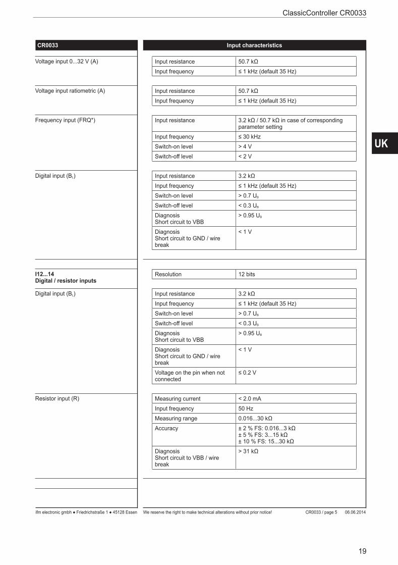
Voltage input 0...32 V (A) Input resistance 50.7 kΩ
Input frequency ≤ 1 kHz (default 35 Hz)
Voltage input ratiometric (A) Input resistance 50.7 kΩ
Input frequency ≤ 1 kHz (default 35 Hz)
Frequency input (FRQ*) Input resistance 3.2 kΩ / 50.7 kΩ in case of corresponding parameter setting
Input frequency ≤ 30 kHz
Switch-on level > 4 V
Switch-off level < 2 V
Digital input (BL) Input resistance 3.2 kΩ
Input frequency ≤ 1 kHz (default 35 Hz)
Switch-on level > 0.7 UB
Switch-off level < 0.3 UB
DiagnosisShort circuit to VBB
> 0.95 UB
DiagnosisShort circuit to GND / wire break
< 1 V
I12...14Digital / resistor inputs
Resolution 12 bits
Digital input (BL) Input resistance 3.2 kΩ
Input frequency ≤ 1 kHz (default 35 Hz)
Switch-on level > 0.7 UB
Switch-off level < 0.3 UB
DiagnosisShort circuit to VBB
> 0.95 UB
DiagnosisShort circuit to GND / wire break
< 1 V
Voltage on the pin when not connected
≤ 0.2 V
Resistor input (R) Measuring current < 2.0 mA
Input frequency 50 Hz
Measuring range 0.016...30 kΩ
Accuracy ± 2 % FS: 0.016...3 kΩ± 5 % FS: 3...15 kΩ± 10 % FS: 15...30 kΩ
DiagnosisShort circuit to VBB / wire break
> 31 kΩ
ClassicController CR0033
20
ifm electronic gmbh ● Friedrichstraße 1 ● 45128 Essen We reserve the right to make technical alterations without prior notice! 06.06.2014CR0033 / page 6
CR0033 Input characteristics
Control systems
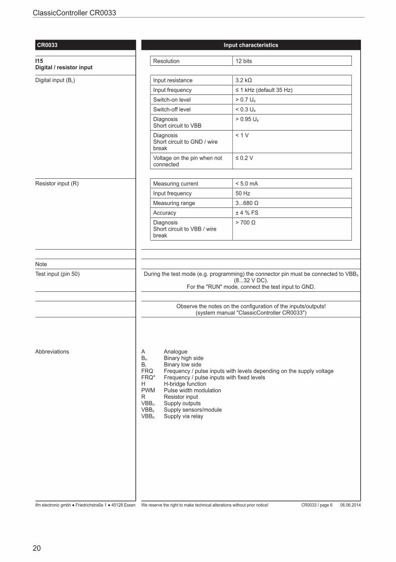
I15Digital / resistor input
Resolution 12 bits
Digital input (BL) Input resistance 3.2 kΩ
Input frequency ≤ 1 kHz (default 35 Hz)
Switch-on level > 0.7 UB
Switch-off level < 0.3 UB
DiagnosisShort circuit to VBB
> 0.95 UB
DiagnosisShort circuit to GND / wire break
< 1 V
Voltage on the pin when not connected
≤ 0.2 V
Resistor input (R) Measuring current < 5.0 mA
Input frequency 50 Hz
Measuring range 3...680 Ω
Accuracy ± 4 % FS
DiagnosisShort circuit to VBB / wire break
> 700 Ω
Note
Test input (pin 50) During the test mode (e.g. programming) the connector pin must be connected to VBBS (8...32 V DC).
For the "RUN" mode, connect the test input to GND.
Observe the notes on the con guration of the inputs/outputs!(system manual "ClassicController CR0033")
Abbreviations ABH
BL
FRQFRQ*HPWMRVBBO
VBBS
VBBR
AnalogueBinary high sideBinary low sideFrequency / pulse inputs with levels depending on the supply voltageFrequency / pulse inputs with xed levelsH-bridge functionPulse width modulationResistor inputSupply outputsSupply sensors/moduleSupply via relay
UK
ClassicController CR0033
21
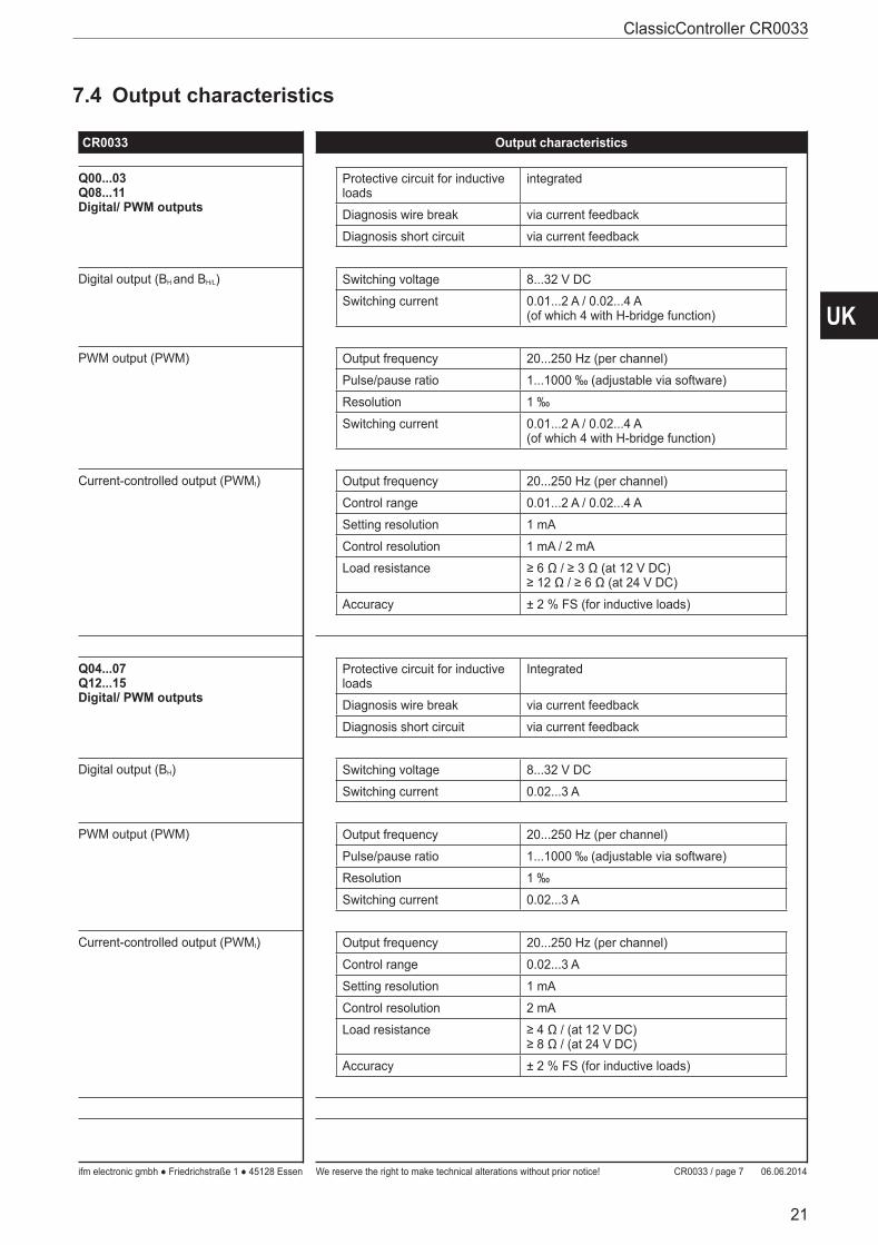
7.4 Output characteristics
ifm electronic gmbh ● Friedrichstraße 1 ● 45128 Essen We reserve the right to make technical alterations without prior notice! 06.06.2014CR0033 / page 7
CR0033 Output characteristics
Control systems
Q00...03Q08...11Digital/ PWM outputs
Protective circuit for inductive loads
integrated
Diagnosis wire break via current feedback
Diagnosis short circuit via current feedback
Digital output (BH and BH/L) Switching voltage 8...32 V DC
Switching current 0.01...2 A / 0.02...4 A(of which 4 with H-bridge function)
PWM output (PWM) Output frequency 20...250 Hz (per channel)
Pulse/pause ratio 1...1000 ‰ (adjustable via software)
Resolution 1 ‰
Switching current 0.01...2 A / 0.02...4 A(of which 4 with H-bridge function)
Current-controlled output (PWMI) Output frequency 20...250 Hz (per channel)
Control range 0.01...2 A / 0.02...4 A
Setting resolution 1 mA
Control resolution 1 mA / 2 mA
Load resistance ≥ 6 Ω / ≥ 3 Ω (at 12 V DC)≥ 12 Ω / ≥ 6 Ω (at 24 V DC)
Accuracy ± 2 % FS (for inductive loads)
Q04...07Q12...15Digital/ PWM outputs
Protective circuit for inductive loads
Integrated
Diagnosis wire break via current feedback
Diagnosis short circuit via current feedback
Digital output (BH) Switching voltage 8...32 V DC
Switching current 0.02...3 A
PWM output (PWM) Output frequency 20...250 Hz (per channel)
Pulse/pause ratio 1...1000 ‰ (adjustable via software)
Resolution 1 ‰
Switching current 0.02...3 A
Current-controlled output (PWMI) Output frequency 20...250 Hz (per channel)
Control range 0.02...3 A
Setting resolution 1 mA
Control resolution 2 mA
Load resistance ≥ 4 Ω / (at 12 V DC)≥ 8 Ω / (at 24 V DC)
Accuracy ± 2 % FS (for inductive loads)
ClassicController CR0033
22
ifm electronic gmbh ● Friedrichstraße 1 ● 45128 Essen We reserve the right to make technical alterations without prior notice! 06.06.2014CR0033 / page 8
CR0033 Output characteristics
Control systems
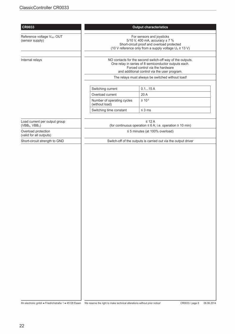
Reference voltage VREF OUT(sensor supply)
For sensors and joysticks5/10 V, 400 mA, accuracy ± 7 %
Short-circuit proof and overload protected(10 V reference only from a supply voltage UB ≥ 13 V)
Internal relays NO contacts for the second switch-off way of the outputs.One relay in series of 8 semiconductor outputs each.
Forced control via the hardwareand additional control via the user program.
The relays must always be switched without load!
Switching current 0.1...15 A
Overload current 20 A
Number of operating cycles (without load)
≥ 10 6
Switching time constant ≤ 3 ms
Load current per output group(VBBR, VBBO)
≤ 12 A(for continuous operation ≤ 6 A; i.e. operation ≥ 10 min)
Overload protection(valid for all outputs)
≤ 5 minutes (at 100% overload)
Short-circuit strength to GND Switch-off of the outputs is carried out via the output driver
UK
ClassicController CR0033
23
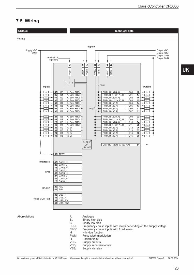
7.5 Wiring
ifm electronic gmbh ● Friedrichstraße 1 ● 45128 Essen We reserve the right to make technical alterations without prior notice! 06.06.2014CR0033 / page 9
CR0033 Technical data
Control systems
Wiring
55 I00 A, BL/H, FRQ 18Q00PWM, BH, (2/4 A)
20G
ND
01V
BB
RS
Inputs
36 I01S
54 I02 A, BL/H, FRQS
35 I03 A, BL/H, FRQS
53 I04 A, BL/H, FRQS
34 I05 A, BL/H, FRQS
52 I06 A, BL/H, FRQS
33 I07 A, BL/H, FRQS
24 I08 A, BL/H, FRQ*S
41 I09 A, BL/H, FRQ*S
23 I10 A, BL/H, FRQ*S
40 I11 A, BL/H, FRQ*S
22 I12 R, BLS
39 I13 R, BLS
21 I14 R, BLS
38 I15 R, BLS
L
17Q01PWM, BH/L, (2/4 A), H L
16Q02PWM, BH, (2/4 A) L
15Q03PWM, BH/L, (2/4 A), H L
14Q04PWM, BH, (3 A) L
13Q05PWM, BH, (3 A) L
12Q06PWM, BH, (3 A) L
11Q07PWM, BH, (3 A) L
02Q08PWM, BH, (2/4 A) L
03Q09PWM, BH/L, (2/4 A), H L
04Q10PWM, BH, (2/4 A) L
05Q11PWM, BH/L, (2/4 A), H L
06Q12PWM, BH, (3 A) L
07Q13PWM, BH, (3 A) L
08Q14PWM, BH, (3 A) L
09Q15PWM, BH, (3 A) L
Outputs
Supply +DCGND
Output +DC
Output GND
37G
ND
Output +DC
42G
ND
relay
A, BL/H, FRQ
10V
BB
S
Interfaces 47 CAN1_H29 CAN1_L
CAN
46 CAN2_H28 CAN2_L45 CAN3_H27 CAN3_L44 CAN4_H26 CAN4_L
25 RxD43 TxDRS-232
30 USB_P48 USB_Nvirtual COM Port31 USB_5 V49 USB_GND
50 TEST
32V
BB
15
terminal 15(ignition)
Output GND
Supply
51VREF OUT (5/10 V, 400 mA)8...32 V
5 / 10 V
relay
19V
BB
O
Abbreviations ABH
BL
FRQFRQ*HPWMRVBBO
VBBS
VBBR
AnalogueBinary high sideBinary low sideFrequency / pulse inputs with levels depending on the supply voltageFrequency / pulse inputs with xed levelsH-bridge functionPulse width modulationResistor inputSupply outputsSupply sensors/moduleSupply via relay

ClassicController CR0033
24
8 Maintenance, repair and disposalThe device is maintenance-free�
► Do not open the housing as the device does not contain any components which can be repaired by the user� The device must only be repaired by the manufacturer�
► Dispose of the device in accordance with the national environmental regulations�
9 Approvals/standardsTest standards and regulations (→ 7 Technical data)The EC declaration of conformity and approvals can be found at: www.ifm.com → Data sheet search → CR0033 → More information