Embed Size (px)
Citation preview

Universal Stationary Battery Analyzer
For testing stationary batteriesused in UPS systems, power
utility, and telecommunicationsindustries
INSTRUCTION MANUAL
®
September 2008168-641G
INNOVATION TECHNOLOGY QUALITY WORLDWIDE
INNOVATION TECHNOLOGY QUALITY WORLDWIDE

This page intentionally left blank.

• 3 •
ContentsCelltron ULTRA

• 4 •
Contents Celltron ULTRA
• 5 •
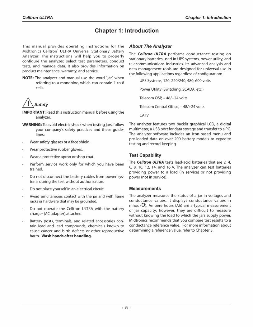
This manual provides operating instructions for the Midtronics Celltron® ULTRA Universal Stationary Battery Analyzer. The instructions will help you to properly configure the analyzer, select test parameters, conduct tests, and manage data. It also provides information on product maintenance, warranty, and service.
NOTE: The analyzer and manual use the word “jar” when referring to a monobloc, which can contain 1 to 8 cells.
SafetyIMPORTANT: Read this instruction manual before using the
analyzer.
WARNING: To avoid electric shock when testing jars, follow your company’s safety practices and these guide-lines:
• Wearsafetyglassesorafaceshield.
• Wearprotectiverubbergloves.
• Wearaprotectiveapronorshopcoat.
• Perform service work only for which you have beentrained.
• Donotdisconnectthebatterycablesfrompowersys-tems during the test without authorization.
• Donotplaceyourselfinanelectricalcircuit.
• Avoid simultaneous contact with the jar and with frame racks or hardware that may be grounded.
• Do not operate the Celltron ULTRA with the batterycharger (AC adapter) attached.
• Battery posts, terminals, and related accessories con-tain lead and lead compounds, chemicals known to cause cancer and birth defects or other reproductive harm. Wash hands after handling.
About The AnalyzerThe Celltron ULTRA performs conductance testing on stationarybatteriesusedinUPSsystems,powerutility,andtelecommunications industries. Its advanced analysis and data management tools are designed for universal use in the following applications regardless of configuration:
UPSSystems,120,220/240,480,600volts
PowerUtility(Switching,SCADA,etc.)
TelecomOSP,–48/+24volts
TelecomCentralOffice,–48/+24volts
CATV
The analyzer features two backlit graphical LCD, a digitalmultimeter,aUSBportfordatastorageandtransfertoaPC.The analyzer software includes an icon-based menu and pre-loaded data on over 200 batterymodels to expeditetesting and record-keeping.
Test CapabilityThe Celltron ULTRA tests lead-acidbatteries that are2, 4,6, 8, 10, 12, 14, and 16V. The analyzer can test batteriesproviding power to a load (in service) or not providing power (not in service).
MeasurementsThe analyzer measures the status of a jar in voltages and conductance values. It displays conductance values in mhos (
Ω
). Ampere hours (Ah) are a typical measurement of jar capacity; however, they are difficult to measure without knowing the load to which the jars supply power. Midtronics recommends that you compare test results to a conductance reference value. For more information about determining a reference value, refer to Chapter 3.
Chapter 1: IntroductionCelltron ULTRA
Chapter 1: Introduction
• 6 •
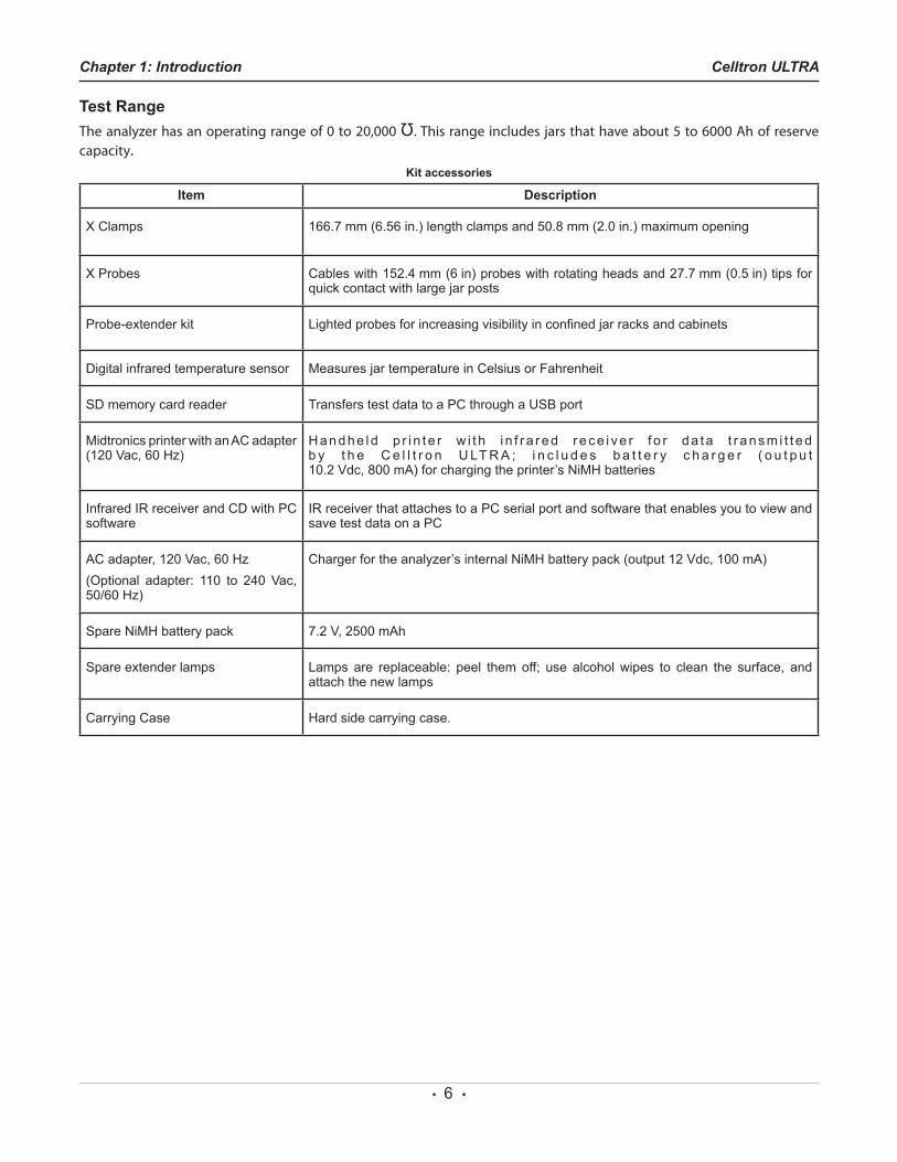
Test RangeTheanalyzerhasanoperatingrangeof0to20,000
Ω
.Thisrangeincludesjarsthathaveabout5to6000Ahofreservecapacity.
Kit accessories
Item Description
X Clamps 166.7 mm (6.56 in.) length clamps and 50.8 mm (2.0 in.) maximum opening
X Probes Cables with 152.4 mm (6 in) probes with rotating heads and 27.7 mm (0.5 in) tips for quick contact with large jar posts
Probe-extender kit Lighted probes for increasing visibility in confined jar racks and cabinets
Digital infrared temperature sensor Measures jar temperature in Celsius or Fahrenheit
SD memory card reader Transfers test data to a PC through a USB port
Midtronics printer with an AC adapter (120 Vac, 60 Hz)
H a n d h e l d p r i n t e r w i t h i n f r a r e d r e c e i v e r f o r d a t a t r a n s m i t t e d b y t h e C e l l t r o n U LT R A ; i n c l u d e s b a t t e r y c h a r g e r ( o u t p u t 10.2 Vdc, 800 mA) for charging the printer’s NiMH batteries
Infrared IR receiver and CD with PC software
IR receiver that attaches to a PC serial port and software that enables you to view and save test data on a PC
AC adapter, 120 Vac, 60 Hz(Optional adapter: 110 to 240 Vac, 50/60 Hz)
Charger for the analyzer’s internal NiMH battery pack (output 12 Vdc, 100 mA)
Spare NiMH battery pack 7.2 V, 2500 mAh
Spare extender lamps Lamps are replaceable: peel them off; use alcohol wipes to clean the surface, and attach the new lamps
Carrying Case Hard side carrying case.
Chapter 1: Introduction Celltron ULTRA
• 7 •
Display, keypad, and connections
3
1
2
4
6
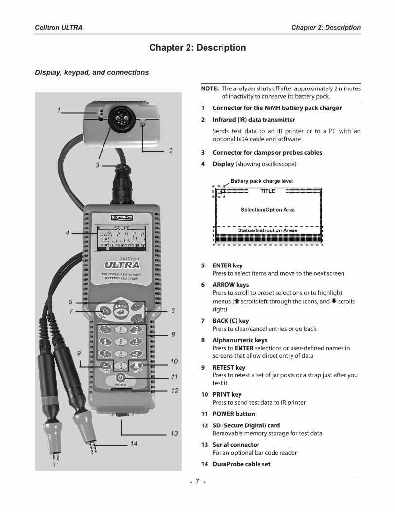
NOTE: Theanalyzershutsoffafterapproximately2minutesof inactivity to conserve its battery pack.
1 Connector for the NiMH battery pack charger
2 Infrared (IR) data transmitter
Sends test data to an IR printer or to a PC with anoptionalIrDAcableandsoftware
3 Connector for clamps or probes cables
4 Display (showing oscilloscope)
TITLE
Status/Instruction Areas
Selection/Option Area
Battery pack charge level
5 ENTER key Presstoselectitemsandmovetothenextscreen
6 ARROW keys Presstoscrolltopresetselectionsortohighlightmenus ( scrolls left through the icons, and scrolls right)
7 BACK (C) key Presstoclear/cancelentriesorgoback
8 Alphanumeric keys PresstoENTER selections or user-defined names in screens that allow direct entry of data
9 RETEST key Presstoretestasetofjarpostsorastrapjustafteryoutest it
10 PRINT key PresstosendtestdatatoIRprinter
11 POWER button
12 SD (Secure Digital) card Removable memory storage for test data
13 Serial connector For an optional bar code reader
14 DuraProbe cable set
57
8
109
11
12
1314
Chapter 2: DescriptionCelltron ULTRA
Chapter 2: Description
• 8 •
Selection screensWhen you turn on the analyzer it will default to the lastmenu screen displayed. To move back to the Main Menu, press the BACK key as each submenu appears.
The Main Menu has six menus: BATTERY SETUP, TEST,REPORTS,UTILITIES SETUP,DMM (DigitalMultimeter), andBATTERY MANAGER. The menus have several submenusor options to help you set up the analyzer for testing, automate portions of the test process, and manage test data. The settings contain factory defaults that you can overwrite using the keypad. For more information, refer to the sections in the manual on selecting test parameters and utilities. The keys you use to enter data depend on the type of selections displayed. There are four types:
Menu iconsA menu icon is a graphical representation of a function you canselectanduse,suchastheBATTERYSETUPiconintheMain Menu.
To select an icon, use the ARROW ( or ) keys to highlight it, and press the ENTER key. To return to the previous menu, press the BACK key.
Scrolling listsScrolling lists contain items that extend above andbelowthe screen or the selection box that contains them. Toindicate that there are more items, the symbols appear to the right of the first item on the list. To select from a list, use the ARROW keys to scroll to the item and press ENTER.
Check boxesListsthatfitthescreenhavecheckboxesbeforeeachitem.Use the ARROW keys toplacethecheck intheboxnextto your selection, or use the numeric keys to enter the item number.PressENTER to select.
Alphanumeric selectionsSome selections require you to use the alphanumeric keypad. These “user-defined” selections are indicated by a blinking horizontal line (cursor) to the right of the last character. Display the character, symbol, or number youwant by rapidly pressing its key as many times as needed. If you pause, the cursor moves to the right. To backspace one character, press the BACK key. To enter a space between characters,pressthekeytwice.PressENTER when finished.
Chapter 2: Description Celltron ULTRA
• 9 •
Chapter 2: DescriptionCelltron ULTRA
Menu StructureThis section describes the menu structure using a tree diagram to help you navigate through the screens. Selectable items are capitalized or in bold, and screen titles are italic.
YoucanfindmoredetailedinformationonhowtoselectoptionsandtestparametersinChapters4and5.
Main Menu IconBattery Setup (Menu Icon)TheBATTERYSETUPmenudisplaysoptionsforsettingnewtestparameters,startingatestwithstoredparameters,deleting test files, and formatting the memory card.
NEW (TEST) (Icon)TheNEW(test)menuenablesyoutosettestparametersforastring.Whenyouselectthisicon,thescreendisplaysRENAMENEWSTRING.
STRING ID RENAME NEW STRING FACTORY TEST (default name) PressENTERtocreateanewstringname(upto500strings).
STRING ID (alphanumeric selection) FACTORY TEST_AstringIDstoresyourtestparameters,eliminatingtheneedtore-ENTERdataeachtimeyoutest.Thelastname created is the default name. Use the BACK key to clear the default characters and the alphanumeric keys tocreateanewname.PressENTERtobeginselectingyourtestparameters.
STRING INFO (scrolling parameters list) [NEW STRING NAME]The string name you created appears at the top of the parameters list. The name is highlighted, enabling you to change it before selecting your test parameters.
TECH ID 1 (default name)PressENTERtocreateatechnicianIDofupto20alphanumericcharacters.TheIDwillbelinkedtothenewstringID.
SELECTTECH(alphanumericselection) Use the BACK key to clear the default characters. Use the alphanumeric keys to create a new name
JARS PER STRINGPressENTER to select the number of jars you are testing per string.
JARS PER STRING (scrolling/numerickeys)
Thenumberofjarsyoucanselect(1to480)de-endsonwhetheryouaretestingJARSONLYorJARS&1STRAP,JARS&2STRAPSandthenumberofPOSTSPERJAR.
VOLTS PER JARPressENTER to select the number of volts per jar.
VOLTSPERJAR(scrolling/numeric) Selectthenumberofvoltsperjar(2,4,6,8,10,12,14,or16V).
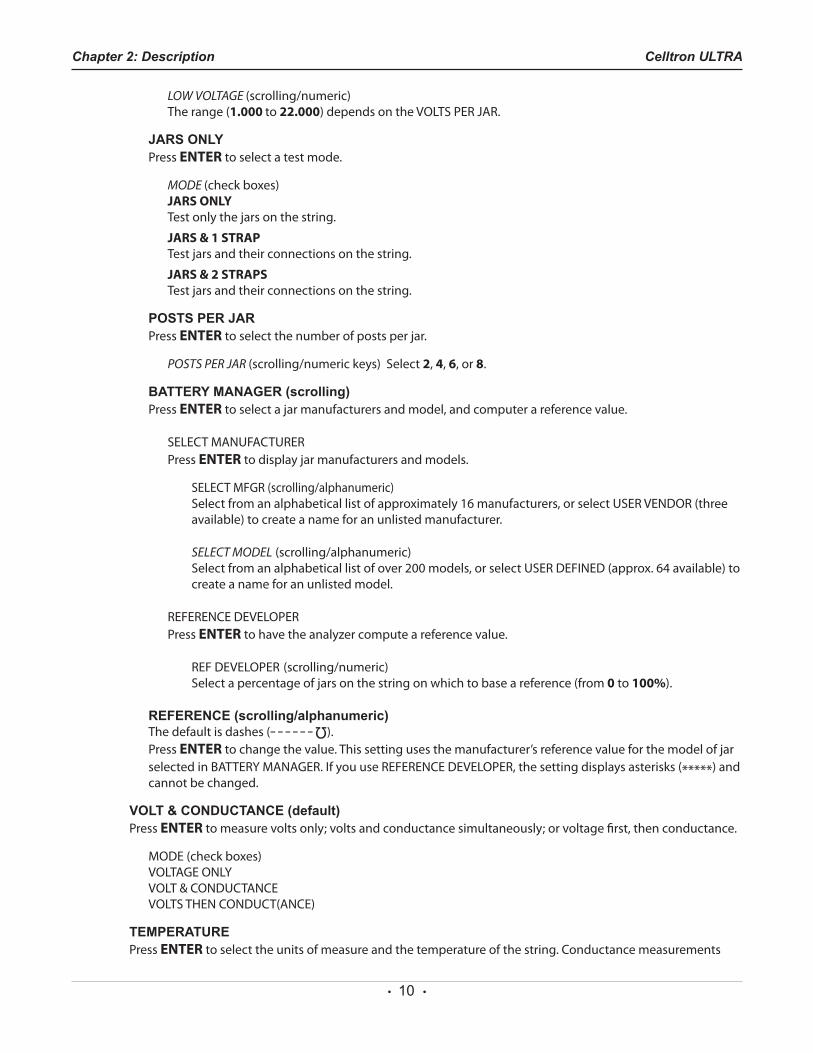
LOW VOLTAGEPressENTER to set the low voltage threshold for a jar.
• 10 •
Chapter 2: Description Celltron ULTRA
LOW VOLTAGE (scrolling/numeric) The range (1.000 to 22.000)dependsontheVOLTSPERJAR.
JARS ONLYPressENTER to select a test mode.
MODE (checkboxes)JARS ONLY Test only the jars on the string.
JARS & 1 STRAPTest jars and their connections on the string.
JARS & 2 STRAPSTest jars and their connections on the string.
POSTS PER JAR PressENTER to select the number of posts per jar.
POSTS PER JAR (scrolling/numerickeys)Select2, 4, 6, or 8.
BATTERY MANAGER (scrolling)PressENTER to select a jar manufacturers and model, and computer a reference value.
SELECTMANUFACTURER PressENTER to display jar manufacturers and models.
SELECTMFGR(scrolling/alphanumeric) Selectfromanalphabeticallistofapproximately16manufacturers,orselectUSERVENDOR(threeavailable) to create a name for an unlisted manufacturer.
SELECT MODEL (scrolling/alphanumeric) Selectfromanalphabeticallistofover200models,orselectUSERDEFINED(approx.64available)tocreate a name for an unlisted model.
REFERENCEDEVELOPER PressENTER to have the analyzer compute a reference value.
REFDEVELOPER (scrolling/numeric) Select a percentage of jars on the string on which to base a reference (from 0 to 100%).
REFERENCE (scrolling/alphanumeric)The default is dashes (– – – – – –
Ω
). PressENTER to change the value. This setting uses the manufacturer’s reference value for the model of jar selectedinBATTERYMANAGER.IfyouuseREFERENCEDEVELOPER,thesettingdisplaysasterisks(*****) and cannot be changed.
VOLT & CONDUCTANCE (default)PressENTER to measure volts only; volts and conductance simultaneously; or voltage first, then conductance.
MODE(checkboxes) VOLTAGEONLY VOLT&CONDUCTANCE VOLTSTHENCONDUCT(ANCE)
TEMPERATUREPressENTER to select the units of measure and the temperature of the string. Conductance measurements
• 11 •
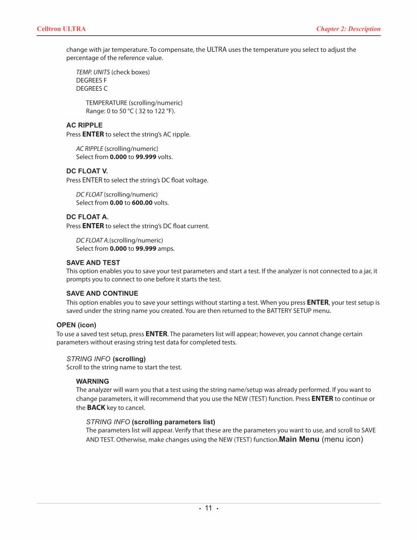
change with jar temperature. To compensate, the ULTRA uses the temperature you select to adjust the percentage of the reference value.
TEMP. UNITS(checkboxes) DEGREESF DEGREESC
TEMPERATURE(scrolling/numeric) Range:0to50°C(32to122°F).
AC RIPPLEPressENTER to select the string’s AC ripple.
AC RIPPLE (scrolling/numeric) Select from 0.000 to 99.999 volts.
DC FLOAT V.PressENTERtoselectthestring’sDCfloatvoltage.
DC FLOAT (scrolling/numeric) Select from 0.00 to 600.00 volts.
DC FLOAT A.PressENTERtoselectthestring’sDCfloatcurrent.
DC FLOAT A.(scrolling/numeric) Select from 0.000 to 99.999 amps.
SAVE AND TESTThis option enables you to save your test parameters and start a test. If the analyzer is not connected to a jar, it prompts you to connect to one before it starts the test.
SAVE AND CONTINUEThisoptionenablesyoutosaveyoursettingswithoutstartingatest.WhenyoupressENTER, your test setup is savedunderthestringnameyoucreated.YouarethenreturnedtotheBATTERYSETUPmenu.
OPEN (icon)To use a saved test setup, press ENTER. The parameters list will appear; however, you cannot change certain parameters without erasing string test data for completed tests.
STRING INFO (scrolling)Scroll to the string name to start the test.
WARNINGTheanalyzerwillwarnyouthatatestusingthestringname/setupwasalreadyperformed.Ifyouwanttochangeparameters,itwillrecommendthatyouusetheNEW(TEST)function.PressENTER to continue or the BACK key to cancel.
STRING INFO (scrolling parameters list)Theparameterslistwillappear.Verifythatthesearetheparametersyouwanttouse,andscrolltoSAVEANDTEST.Otherwise,makechangesusingtheNEW(TEST)function.Main Menu (menu icon)
Chapter 2: DescriptionCelltron ULTRA
• 12 •
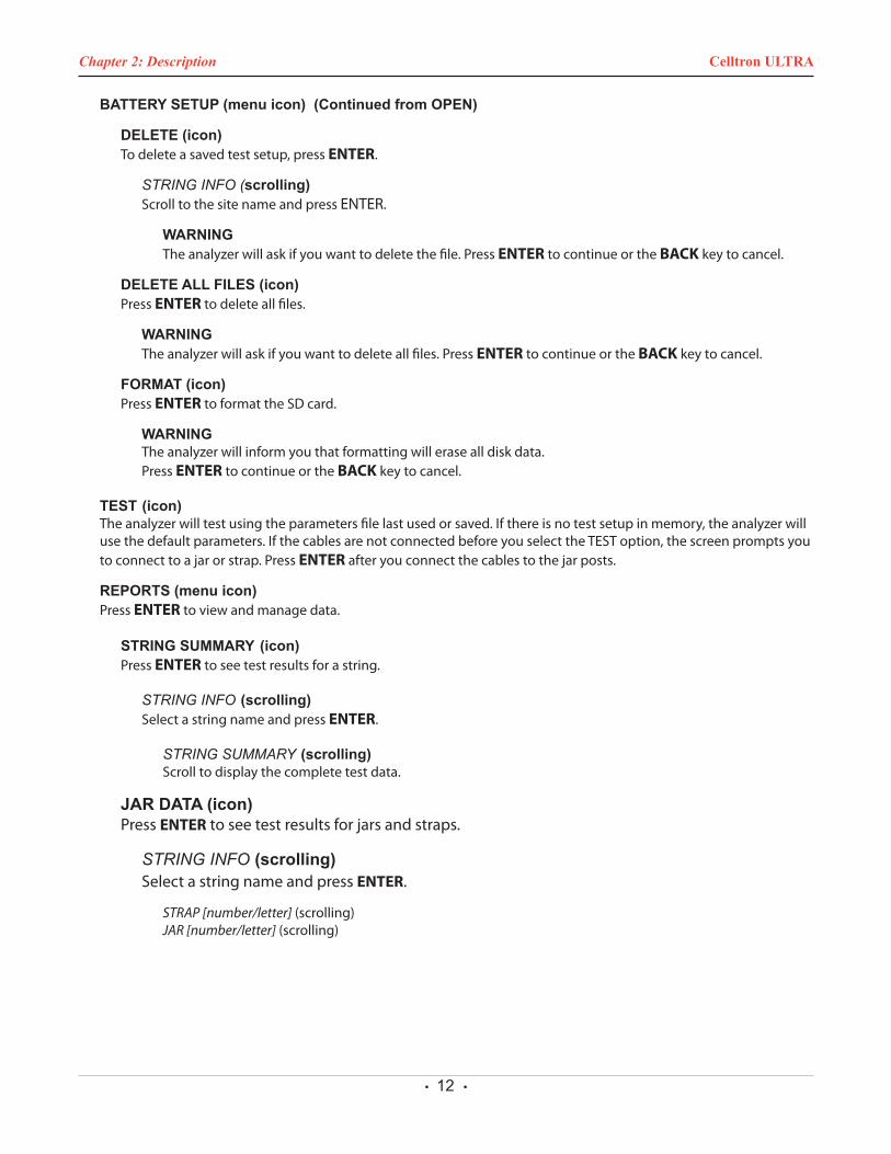
BATTERY SETUP (menu icon) (Continued from OPEN)
DELETE (icon)To delete a saved test setup, press ENTER.
STRING INFO (scrolling)Scroll to the site name and press ENTER.
WARNINGTheanalyzerwillaskifyouwanttodeletethefile.PressENTER to continue or the BACK key to cancel.
DELETE ALL FILES (icon)PressENTER to delete all files.
WARNINGTheanalyzerwillaskifyouwanttodeleteallfiles.PressENTER to continue or the BACK key to cancel.
FORMAT (icon)PressENTER toformattheSDcard.
WARNINGThe analyzer will inform you that formatting will erase all disk data. PressENTER to continue or the BACK key to cancel.
TEST (icon)The analyzer will test using the parameters file last used or saved. If there is no test setup in memory, the analyzer will usethedefaultparameters.IfthecablesarenotconnectedbeforeyouselecttheTESToption,thescreenpromptsyoutoconnecttoajarorstrap.PressENTER after you connect the cables to the jar posts.
REPORTS (menu icon)PressENTER to view and manage data.
STRING SUMMARY (icon)PressENTER to see test results for a string.
STRING INFO (scrolling) Select a string name and press ENTER.
STRING SUMMARY (scrolling) Scroll to display the complete test data.
JAR DATA (icon)PressENTER to see test results for jars and straps.
STRING INFO (scrolling) Select a string name and press ENTER.
STRAP [number/letter] (scrolling) JAR [number/letter] (scrolling)
Chapter 2: Description Celltron ULTRA
• 13 •
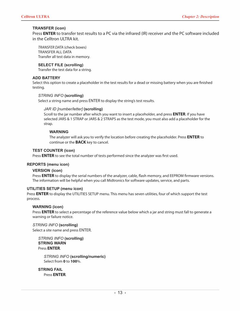
TRANSFER (icon)PressENTERtotransfertestresultstoaPCviatheinfrared(IR)receiverandthePCsoftwareincludedin the Celltron ULTRA kit.
TRANSFER DATA(checkboxes) TRANSFERALLDATA Transfer all test data in memory.
SELECT FILE (scrolling)Transfer the test data for a string.
ADD BATTERYSelect this option to create a placeholder in the test results for a dead or missing battery when you are finished testing.
STRING INFO (scrolling)Select a string name and press ENTER to display the string’s test results.
JAR ID [number/letter] (scrolling) Scroll to the jar number after which you want to insert a placeholder, and press ENTER. If you have selectedJARS&1STRAPorJARS&2STRAPSasthetestmode,youmustalsoaddaplaceholderforthestrap.
WARNINGTheanalyzerwillaskyoutoverifythelocationbeforecreatingtheplaceholder.PressENTER to continue or the BACK key to cancel.
TEST COUNTER (icon)PressENTER to see the total number of tests performed since the analyzer was first used.
REPORTS (menu icon)VERSION (icon)PressENTERtodisplaytheserialnumbersoftheanalyzer,cable,flashmemory,andEEPROMfirmwareversions.The information will be helpful when you call Midtronics for software updates, service, and parts.
UTILITIES SETUP (menu icon)PressENTERtodisplaytheUTILITIESSETUPmenu.Thismenuhassevenutilities,fourofwhichsupportthetestprocess.
WARNING (icon)PressENTER to select a percentage of the reference value below which a jar and string must fall to generate a warning or failure notice.
STRING INFO (scrolling)Select a site name and press ENTER.
STRING INFO (scrolling)STRING WARNPressENTER.
STRING INFO (scrolling/numeric)Select from 0 to 100%.
STRING FAILPressENTER.
Chapter 2: DescriptionCelltron ULTRA
• 14 •
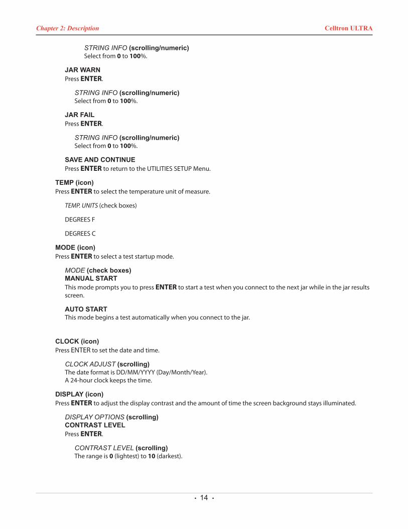
STRING INFO (scrolling/numeric)Select from 0 to 100%.
JAR WARNPressENTER.
STRING INFO (scrolling/numeric)Select from 0 to 100%.
JAR FAILPressENTER.
STRING INFO (scrolling/numeric)Select from 0 to 100%.
SAVE AND CONTINUEPressENTERtoreturntotheUTILITIESSETUPMenu.
TEMP (icon)PressENTER to select the temperature unit of measure.
TEMP. UNITS (checkboxes)
DEGREESF
DEGREESC
MODE (icon)PressENTER to select a test startup mode.
MODE (check boxes)MANUAL STARTThis mode prompts you to press ENTERtostartatestwhenyouconnecttothenextjarwhileinthejarresultsscreen.
AUTO STARTThis mode begins a test automatically when you connect to the jar.
CLOCK (icon)PressENTER to set the date and time.
CLOCK ADJUST (scrolling) ThedateformatisDD/MM/YYYY(Day/Month/Year). A24-hourclockkeepsthetime.
DISPLAY (icon)PressENTER to adjust the display contrast and the amount of time the screen background stays illuminated.
DISPLAY OPTIONS (scrolling)CONTRAST LEVELPressENTER.
CONTRAST LEVEL (scrolling)The range is 0 (lightest) to 10 (darkest).
Chapter 2: Description Celltron ULTRA
• 15 •
Page 22 168-641G
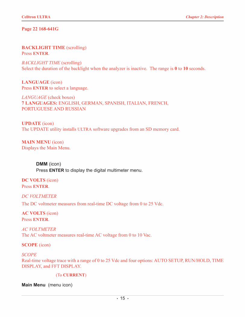
BACKLIGHT TIME (scrolling) Press ENTER.
BACKLIGHT TIME (scrolling)Select the duration of the backlight when the analyzer is inactive. The range is 0 to 10 seconds.
LANGUAGE (icon) Press ENTER to select a language.
LANGUAGE (check boxes) 7 LANGUAGES: ENGLISH, GERMAN, SPANISH, ITALIAN, FRENCH,PORTUGUESE AND RUSSIAN
UPDATE (icon)The UPDATE utility installs ULTRA software upgrades from an SD memory card.
MAIN MENU (icon) Displays the Main Menu.
DMM (icon) Press ENTER to display the digital multimeter menu.
DC VOLTS (icon)Press ENTER.
DC VOLTMETERThe DC voltmeter measures from real-time DC voltage from 0 to 25 Vdc.
AC VOLTS (icon)Press ENTER.
AC VOLTMETERThe AC voltmeter measures real-time AC voltage from 0 to 10 Vac.
SCOPE (icon)
SCOPEReal-time voltage trace with a range of 0 to 25 Vdc and four options: AUTO SETUP, RUN/HOLD, TIME DISPLAY, and FFT DISPLAY.
(To CURRENT)
Main Menu (menu icon)
Chapter 2: DescriptionCelltron ULTRA
• 16 •
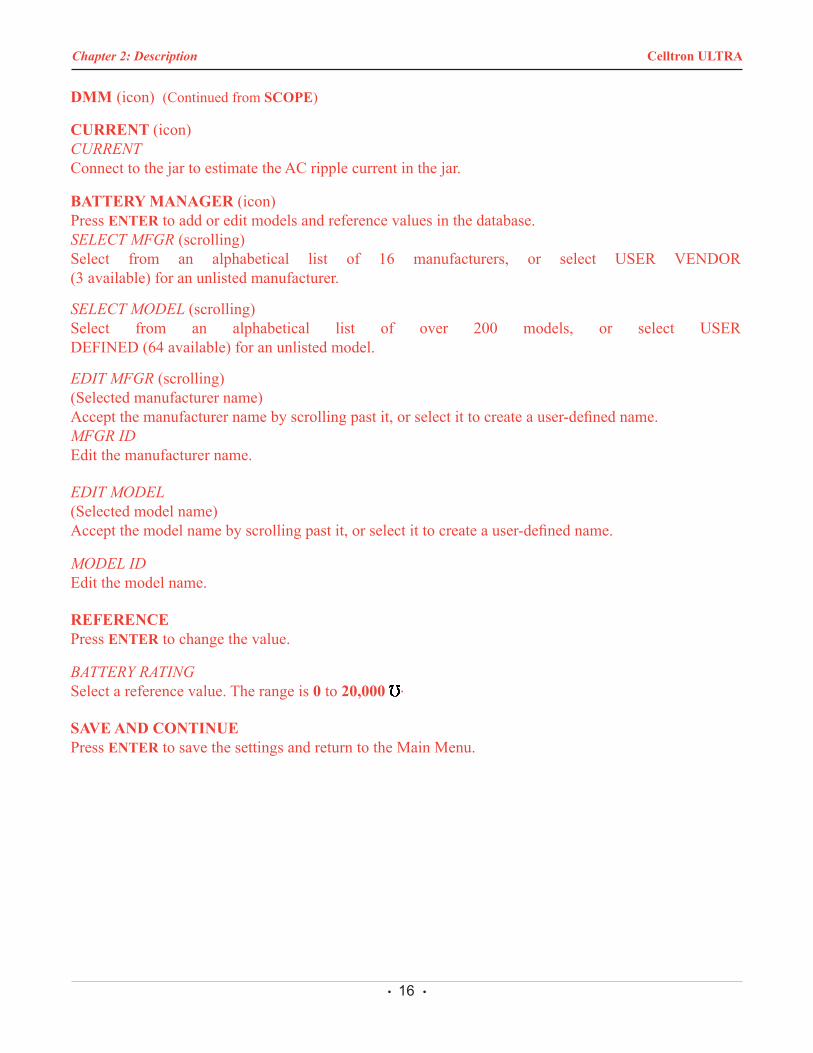
DMM (icon) (Continued from SCOPE)
CURRENT (icon)CURRENT Connect to the jar to estimate the AC ripple current in the jar.
BATTERY MANAGER (icon) Press ENTER to add or edit models and reference values in the database.SELECT MFGR (scrolling)Select from an alphabetical list of 16 manufacturers, or select USER VENDOR (3 available) for an unlisted manufacturer.
SELECT MODEL (scrolling)Select from an alphabetical list of over 200 models, or select USER DEFINED (64 available) for an unlisted model.
EDIT MFGR (scrolling) (Selected manufacturer name)Accept the manufacturer name by scrolling past it, or select it to create a user-defined name.MFGR ID Edit the manufacturer name.
EDIT MODEL (Selected model name)Accept the model name by scrolling past it, or select it to create a user-defined name.
MODEL ID Edit the model name.
REFERENCE Press ENTER to change the value.
BATTERY RATING Select a reference value. The range is 0 to 20,000 .
SAVE AND CONTINUE Press ENTER to save the settings and return to the Main Menu.
Chapter 2: Description Celltron ULTRA

• 17 •
Chapter 2: DescriptionCelltron ULTRA

• 18 •
Chapter 2: Description Celltron ULTRA

• 19 •
Chapter 2: DescriptionCelltron ULTRA
• 20 •
Before you test a string• Notethevoltageofthejars
• Determineareferencevalue
• SetoptionsintheUTILITIESSETUPmenu
• SettestparametersintheBATTERYSETUPmenu
Reference values are average conductance values from a sampleofstrongjarssimilarinconditionandage.Generally,asampleof30neworhealthybatteriesistestedtoobtainavaluerepresentativeofanewonlinebattery90daysafterinstallation.Youcancomparereferencevaluestotestresultsfrom a string. The differences between test results and reference values help you determine the string’s capacity to provideenoughconductancefortheload.Differencescanreflecthowastringwastreated,installed,ormaintained.
Options in determining a reference valueIf you want a value specific to the string you are testing, Midtronics recommends that you create your own reference value. The following options are listed in the order you should take to obtain a reference value.
• Consult your company documentation for reference values that were created for the string you are testing.
• Test a sample of jars. Refer to Testing a sample of jars to establish a reference value in this chapter.
• Test the jars in the string and use the highest conduc-tance value as a reference value.
• UsetheaveragefromSTRINGSUMMARY after you test the string. Refer to Using the average in STRING SUMMA-RY in this chapter).
• UseREFERENCEDEVELOPER todeterminea referencevalue based on a selected percentage of jars on the string with the highest conductance value.
• Use the reference value in the BATTERY MAN-AGER database for the model of jar you are testing. If the model is not in the database, contact the battery manufacturer or visit www.midtronics.com for a list of reference values for common jar types.
The reference values in STRING SUMMARY, BATTERYMANAGER, and on the website are only guidelines.Midtronics updates the website with new reference values when they are created. If you create a reference value for a jar model, e-mail the value and information to [email protected] fax it to 630-323-7752 (Attn: Referencevalue list).
CAUTION: DonotusetheCelltronULTRAtotesttheentirestringatonce.Testonlyindividualjars/batteries.
IMPORTANT: Always test on the lead post for the most con-sistent results. To prevent lower measures, avoid tests on stainless-steel hardware or bolts.
Notes: • The first time you turn on or connect the Celltron UL-
TRA, it will display a reminder to set preferences for the temperature units (Celsius or Fahrenheit) and thejarandstringWARN/FAILthresholds.Althoughyou can press the BACK key to bypass the message, it will continue to appear until you change or accept the default settings.
• To protect its circuitry, the analyzer will not turn on if the clamps/probes are connected in reverse polarity(red to negative, black to positive).
• Poweroutagescanaffect test results.Donot test thestring if a power outage occurred recently and the string is boost-charged.
• If the last file created, opened, or used does not match any files on the memory card, the analyzer will beep and display FILE NOT FOUND. The analyzer’s internalEEPROMmemory stores the last test used.When theanalyzer powers on, it looks for the last file used on the memory card. To prevent the message from reappear-ing,insertthecardcontainingthefile,openanexistingfile, or create a new file on the card.
Chapter 3: Determining a reference value Celltron ULTRA
Chapter 3: Determining a reference value
• 21 •
Testing a sample of jars1. Chooseatleast30jarsfromonemanufacturerwiththe
samemake,model,powerrating,age(within6months),and service history.
2. Recordthisinformationaboutthejars:
• Jarmanufacturer
• Model number
• Dateofmanufacture
• Dateofinstallation
• Condition in which the jar operates, such as charge voltage (volts per cell), temperature, and DCcurrentthroughthejar
• Visible warnings, such as leaking acid, corrosion, or distorted jar cases
3. Test the jars. See Chapter 6: Testing.
4. Testonejarfivetimesinarowonfloatcharge.Conduc-tance results should be within ± 2%ofeachother.
NOTE: If the test results do not conform to this pattern, an electrical signal might be present in the system.
5. Calculatetheaverageconductanceofthejars.Donotincludejarsthatarehigherorlowerthan30%fromtheaverage because they might be outside an acceptable range.
Using the average in STRING SUMMARYIf you cannot obtain a reference value for a string, test the string and use the average conductance value (AVG.MHOS) in the STRING SUMMARY as your reference value.If jars in the string have been replaced recently, test the new jars, especially if theycorrelate to theHIGH jar valueinSTRINGSUMMARY.Formoreinformation,see Chapter 7: Test results.)
Chapter 3: Determining a reference valueCelltron ULTRA
• 22 •
TheUTILITIESSETUPmenuhaseightoptions,threeofwhichsupport the test process. If you make no selections, the analyzerusesthedefaultsettings.ForthecriticalWARNINGand TEMP settings, the analyzer will remind you with aPREFERENCESNOTSETmessageuntilyouchangeoracceptthe default settings.
The utilities are:
• WARNING (voltage threshold for failing jars andstrings)
• TEMP(CelsiusorFahrenheit)
• MODE(autoormanualteststartup)
• CLOCK (date and time)
• DISPLAY(contrastandbacklightduration)
• LANGUAGE(selectingthelanguage)
• UPDATE(updatetheCelltronULTRAsoftware)
Selecting a warn/fail threshold (WARNING)TheWARNING utility enables you to set the percentagesof the reference value below which a jar and string must falltogenerateaWARNoraFAILnoticeontheprintedtestresults.Aquestionmark(?)appearsnexttojarsandstringsasawarning.Anexclamationmark(!)appearsifthejarorstring is failing.
Table 4: Defaults for a jar and string in service
STRING WARN <70% JAR WARN <70%
STRING FAIL <60% JAR FAIL <60%
1. PresstheARROW keystohighlighttheWARNINGiconintheUTILITIESSETUPmenu,andpressENTER.
2. PresstheARROW keystoselectaSTRINGNAME,andpress .
3. PresstheARROW keystoscrolltoaselection:STRINGWARN,STRINGFAIL, JARWARN,orJARFAILandpressENTER. Press the ARROW keys to set percentages, and press ENTER to select. Repeat the process for each screen you want to print.
Selecting Celsius or Fahrenheit (TEMP)Select Celsius or Fahrenheit as a unit of measure before setting your test parameters in BATTERY SETUP. The lastsavedTEMPselectionbecomesthedefaultunitofmeasure.
1. PresstheARROW keystohighlighttheUTILITIESSET-UPicon,andpressENTER.
2. PresstheARROW keystohighlighttheTEMPicon,andpress ENTER.
3. Press the ARROW keys (or use the numer-ic keys) to check the box next to DEGREES F or DEGREESC,andpressENTER to select.
Selecting a manual or automatic test-start mode (MODE)The MODE utility has two test-start modes. AUTO STARTstartsatestautomaticallywhenyouconnecttothenextjarfrom the jar results screen. The setting allows you to keep your hands free to use probes.
MANUALSTART,whichisthedefault,promptsyoutopressENTER to begin a test after you connect to the jar.
1. PresstheARROW keystohighlighttheMODEiconintheUTILITIESSETUPmenu,andpressENTER.
2. Press theARROW keys (or use the numeric keys) to checktheboxnexttoMANUALSTARTorAUTOSTART.
3. PressENTER to select.
4. Press theBACK key to return to theUTILITIESSETUPmenu.
Setting the date and time (CLOCK)Theclockutilityincludessettingsfortheanalyzer’s24-hourinternal clock and for the date and time, which are printed on test reports. Although the date and time are set at the factory, you may need to make changes based on your time zone.
1. Pressandhold thePOWER button until the analyzer turns on.
2. PresstheARROW keystohighlighttheUTILITIESSET-
Chapter 4: Utilities Celltron ULTRA
Chapter 4: Utilities
• 23 •
UPicon,andpressENTER.
NOTE: If you select an option you do not want, press EN-TER to return to the Main Menu.
3. Use the ARROW keys to highlight the CLOCK icon, and press ENTER.
4. Tohighlightthecharactersyouwanttochange,pressENTER. To move backward, press BACK. To make changes, press the ARROW keys to select the number of the month, day, year, hour, and minutes.
5. To have the analyzer accept your changes, press EN-TER to move past the minutes setting.
Adjusting the display contrast (CONTRAST LEVEL)
1. PresstheARROW keystohighlighttheUTILITIESSET-UPicon,andpressENTER.
2. PresstheARROW keystohighlighttheDISPLAYicon,and press ENTER.
3. PresstheARROW keystohighlightCONTRASTLEVEL,and press ENTER.
4. Press theARROW keys (or use the numeric keys) to adjust the contrast from 0 (lightest) to 10 (darkest).
5. PressENTER to select.
Adjusting the display’s backlight duration (BACKLIGHT TIME)
This option turns off the screen illumination after a selected period of time to conserve the analyzer’s battery pack.
1. PresstheARROW keystohighlighttheUTILITIESSET-UPicon,andpressENTER.
2. PresstheARROW keystohighlighttheDISPLAYicon,and press ENTER.
3. PresstheARROW keys to highlight BACKLIGHTTIME,and press ENTER.
4. Press theARROW keys (or use the numeric keys) to
adjust the time the display stays backlitfrom0seconds(off)to10seconds.
5. PressENTER to select.
Selecting the language (LANGUAGE)T h e r e a r e s e v e n s e l e c t a b l e l a n g u a g e s i n t h e Cel l t ron ULTRA sof t ware for the display and pr inted repor ts :
1. PresstheARROW keystohighlighttheUTILITIESSET-UPicon,andpressENTER.
2. Press the ARROW keys to highlight the LANGUAGEicon, and press ENTER.
3. PresstheARROW keys (or use the numeric keypad) to move the dot to the option button of your choice.
4. PressENTER to accept.
Using UPDATE to install new softwareThis uti l ity enables you to update the analyzer ’s s o f t wa r e u s i n g a n SD c a r d . Con t a c t y o u r Midtronics sales representative or Midtronics Customer service for information about the current version.
To update the software from a SD card containing theupdate files:
1. Insert the new memory card into the analyzer and press the POWER key.
2. FILENOTFOUNDwillappearonthedisplay.
3. PresstheBACK key twice to display the Main Menu.
4. PresstheARROW keystohighlighttheUTILITIESSET-UPicon,andpressENTER.
5. PresstheARROW keystohighlighttheUPDATEicon,and press ENTER.
6. SOFTWAREWILLBECHANGED,DOYOUWANTTOCON-TINUE? Press ENTER to update the analyzer’s soft-ware.
NOTE: It will take several minutes to complete the update.
Chapter 4: UtilitiesCelltron ULTRA

• 24 •
Chapter 4: Utilities Celltron ULTRA
• 25 •
Ifyouaretestingastringforthefirsttime,usetheNEWtestmenuinBATTERYSETUPtocreateastringnameandchooseits test parameters. If you make no selections, the analyzer uses the default settings when you test the string. (See Menu structure in Chapter 2.)
To begin: Make sure the memory card is inserted correctly. Thecard’slabelshouldfacethekeypad.PressandholdthePOWER button.
• The first time you turn on or connect the Celltron ULTRA, it will display a reminder to set preferences for the temperature units (Celsius or Fahrenheit) and the jar and string WARN/FAIL thresholds.Although you can press the BACK key to bypass the message, it will continue to appear until you change or accept the default settings.
• To protect its circuitry, the analyzer will not turn oniftheclamps/probesareconnectedinreversepolarity (red to negative, black to positive).
• If the last file created, opened, or used does not match any files on the memory card, the analyzer will beep and display FILE NOT FOUND. Theanalyzer’s internal EEPROM memory stores thelast test used.When the analyzer powers on, itlooks for the last file used on the memory card. To prevent the message from reappearing, insert the card containing thefile, openanexistingfile, orcreate a new file on the card.
Creating a string name (FACTORY TEST)A string name stores your test parameters, eliminating the need to reenter data each time you test. The default name isFACTORYTEST(orthelastnamecreated),whichyoucanoverwrite with any 20-character combination of letters,numbers, or symbols using the alphanumeric keypad.
1. PresstheARROW keystohighlighttheBATTERYSET-UPicon,andpressENTER.
2. PresstheARROW keystohighlighttheNEWicon,andpress ENTER.
3. WhenthepromptRENAMENEWSTRINGappears,press
ENTER to create a new string name.
4. Thedefaultstringnameorthelaststringtestedwillap-pears.PressENTER for the editing screen.
5. The cursor will blink to the right of the last character. To backspace and overwrite characters, press the BACK key as many times as needed.
6. Enter the character, symbol, or number youwant byrapidly pressing its key as many times as needed. If you pause, the cursor moves to the right. To enter a space between characters, press the key twice.
7. PressENTER when finished.
8. The string name you created appears at the top of the parameters list. The name is highlighted, enabling you press ENTER to change it again before selecting your test parameters. To continue selecting parameters press the ARROW keys. CreatingaTECHID
Press ENTER to create a technician ID of up to 20alphanumericcharacters.The IDwillbe linkedtothenewstringID.ThedefaultnameisTECHID(orthelastIDcreated),which you can overwrite with any combination of letters, numbers, or symbols using the alphanumeric keypad.
1. PresstheARROW keystohighlightTECHID1(factorydefault)orthelastIDcreated.
2. Theeditingscreenwillappear.Thecursorwillblinktothe right of the last character. To backspace and over-write characters, press the BACK key as many times as needed.
3. Enter the character, symbol, or number youwant byrapidly pressing its key as many times as needed. If you pause, the cursor moves to the right. To enter a space between characters, press the key twice.
4. PressENTER when finished.
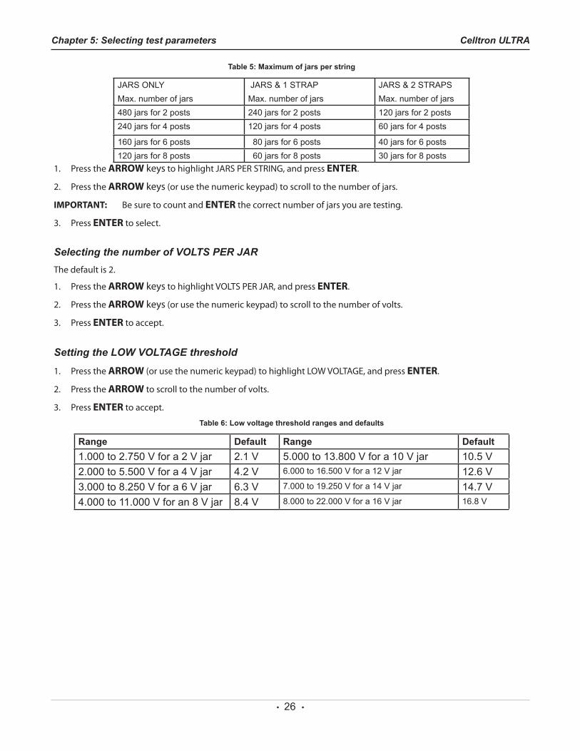
Selecting the number of JARS PER STRINGThedefaultis24.ThenumberofjarsyoucantestdependsonwhetheryouaretestingJARSONLY,JARS&1STRAP,orJARS&2STRAPSandnumberofPOSTSPERJAR.
Chapter 5: Selecting test parametersCelltron ULTRA
Chapter 5: Selecting test parameters
• 26 •
Table 5: Maximum of jars per string
JARS ONLYMax. number of jars
JARS & 1 STRAPMax. number of jars
JARS & 2 STRAPSMax. number of jars
480 jars for 2 posts 240 jars for 2 posts 120 jars for 2 posts240 jars for 4 posts 120 jars for 4 posts 60 jars for 4 posts
160 jars for 6 posts 80 jars for 6 posts 40 jars for 6 posts120 jars for 8 posts 60 jars for 8 posts 30 jars for 8 posts
1. PresstheARROW keystohighlightJARSPERSTRING,andpressENTER.
2. PresstheARROW keys (or use the numeric keypad) to scroll to the number of jars.
IMPORTANT: Be sure to count and ENTER the correct number of jars you are testing.
3. PressENTER to select.
Selecting the number of VOLTS PER JARThedefaultis2.
1. PresstheARROW keystohighlightVOLTSPERJAR,andpressENTER.
2. PresstheARROW keys (or use the numeric keypad) to scroll to the number of volts.
3. PressENTER to accept.
Setting the LOW VOLTAGE threshold
1. PresstheARROW(orusethenumerickeypad)tohighlightLOWVOLTAGE,andpressENTER.
2. PresstheARROW to scroll to the number of volts.
3. PressENTER to accept.
Table 6: Low voltage threshold ranges and defaults
Range Default Range Default1.000 to 2.750 V for a 2 V jar 2.1 V 5.000 to 13.800 V for a 10 V jar 10.5 V2.000 to 5.500 V for a 4 V jar 4.2 V 6.000 to 16.500 V for a 12 V jar 12.6 V3.000 to 8.250 V for a 6 V jar 6.3 V 7.000 to 19.250 V for a 14 V jar 14.7 V4.000 to 11.000 V for an 8 V jar 8.4 V 8.000 to 22.000 V for a 16 V jar 16.8 V
Chapter 5: Selecting test parameters Celltron ULTRA
• 27 •
Selecting a test mode (JARS ONLY)ThedefaultisJARSONLY.
1. PresstheARROW keystohighlightJARSONLY,JARS&1STRAP,orJARS&2STRAPSintheSTRING INFO list, and press ENTER.
2. PresstheARROW keys (or use the numeric keypad) to check theboxnext to JARSONLY, JARS&1STRAP,orJARS&2STRAPS.
3. PressENTER to accept.
Selecting the number of POSTS PER JARThedefaultis2.
1. Press theARROW keys to highlight POSTS PER JAR,and press ENTER.
2. PresstheARROW keys (or use the numeric keypad) to scroll to the number of posts.
3. PressENTER to accept. Using a reference value from the database (BATTERYMANAGER)
If there is no reference value for the string you are testing, you can use a reference value for the jar model in the BATTERYMANAGERdatabase.The referencevalue isusedonly for this particular test setup. If you want to permanently add a reference value or a new jar model to the database, see “Adding jar model information to the database.”
1. PresstheARROWkeystohighlightBATTERYMANAG-ER,andpressENTER.
2. PresstheARROWkeystohighlightSELECTMANUFAC-TURER,andpressENTER.
3. PresstheARROW keys to highlight a manufacturer (or USERVENDORforanunlistedmanufacturer),andpressENTER.
4. PresstheARROW keys to highlight a model name.
5. PressENTER to accept.
Using REFERENCE DEVELOPER to calculate a referencevalue
If there is no reference value for the string you are testing, you can use REFERENCE DEVELOPER to calculate a valuebasedonanaverageofthetop30%ofthejarsinthestring,
or on a percentage of your choice.
1. PresstheARROWkeystohighlightBATTERYMANAG-ER,andpressENTER.
2. PresstheARROWkeystohighlightREFERENCEDEVEL-OPER,andpressENTER.
3. PressENTER to accept the default, or press the AR-ROW keys (or use the numeric keypad) to select the percentage of jars in the string.
4. PressENTER to accept.
Selecting a REFERENCE value This setting uses the manufacturer’s reference value for the model of jar selected in Battery Manager. If you use REFERENCE DEVELOPER, the setting displays asterisks(*****)andcannotbechanged.Therangeis0(testwithoutareferencevalue)to20,000 . If you test without a reference value, dashes appear in reference fields on the display and in the test results.
1. Press theARROW keys to highlight REFERENCE, andpress ENTER.
2. PresstheARROW keys (or use the numeric keypad) to select a value.
3. PressENTER to accept.
Selecting what to measure (VOLT & CONDUC-TANCE)
ThedefaultisVOLT&CONDUCTANCE.
1. PresstheARROWkeystohighlightVOLT&CONDUC-TANCE,andpressENTER.
2. PresstheARROW keys (or use the numeric keypad) to checktheboxnexttoyourchoice:VOLTAGEONLY,VOLT&CONDUCTANCE,VOLTSTHENCONDUCT(ANCE).
NOTE: SelectVOLTSTHENCONDUCT(ANCE)ifyouaremea-suring conductance and do not want conductance testing to affect your voltage measurements. After you measure the voltage of the jars (or jars and straps) in a string, disconnect, then reconnect to the first jar in the string to complete the test by measur-ing conductance.
Chapter 5: Selecting test parametersCelltron ULTRA
• 28 •
3. PressENTER to accept.
NOTE: Once you start the conductance portion of the VOLTSTHEN CONDUCTANCE test, youwill not beable retest voltage. Be sure to review your voltage reading before you start your conductance portion of the test.
Selecting the string TEMPERATUREThe default is 25 °C (77 °F). Conductance measurementsvary by jar temperature. To compensate, the analyzer uses theTEMPERATUREvalue to adjust thepercentageofthe referencevalueyou set in theUTILITIESSETUPas theWARN/FAIL threshold. The percent is compensated to 25°C (77 °F). Compensation is adjusted at 0.7% per degreeCelsiusbetween0°C and 35 °C. (The kit includes an infrared temperature sensor and instructions.)
1. Press the ARROW keys to highlight TEMPERATURE,and press ENTER.
2. PresstheARROW keys (or use the numeric keypad) to select a value.
3. PressENTER to accept.
Saving the BATTERY SETUP
To save your settings for later use, press the ARROW keys tohighlightSAVEANDCONTINUE,andpressENTER.Youare returned to the NEWtestmenu.TouseasavedBATTERY
SETUP to test a string, see Selecting the TEST option in Chapter 6: Testing.
To save your settings for immediate testing, connect the clamps or probes and press the ARROWtohighlightSAVEANDTEST. Press ENTER to start the test. (See Chapter 6: Testing.)
Adding jar model information to the databaseTo add new jar models and conductance reference values tothedatabase,useBATTERYMANAGERintheMainMenu.TheBATTERYMANAGERavailableinBATTERYSETUPallowsyou to change a reference value only for a particular data file. It does not save the change as a selection for new test setups.YoucanalsoeditamodelnameoraddanewmodelusingBATTERYMANAGERintheMainMenu.
Changing a reference value
1. PresstheARROWkeystohighlighttheBATTERYMAN-AGERintheMainMenu,andpressENTER.
2. PresstheARROW keys to select a manufacturer, and press ENTER.
3. To change a reference value for a model in the database, press the ARROW keys to select the model name, and press ENTER.
4. IntheEDIT MFGR screen, press the DOWN ARROW to
Chapter 5: Selecting test parameters Celltron ULTRA
• 29 •
selectREFERENCE,andpressENTER.
NOTE: If you change the model name and save it, the new name overwrites the original model name in the da-tabase.
5. PresstheARROW keys (or use the numeric keypad) to select a new reference value, and press ENTER.
6. Tosave,presstheDOWN ARROWtoselectSAVEANDCONTINUE,andpressENTER.
Adding a jar model
1. PresstheARROW keystohighlighttheBATTERYMAN-AGERintheMainMenu,andpressENTER.
2. PresstheARROW keys to select a manufacturer, and press ENTER.
3. PresstheARROW keys to select one of the numbered USERDEFINEDnames, and press ENTER.
4. IntheMODEL IDscreen,yourUSERDEFINEDselectionishighlighted.PressENTER to change the name.
5. The cursor blinks to the right of the last space or charac-terinthename.Displaythecharacter,symbol,ornum-ber you want by rapidly pressing its key as many times as needed. If you pause, the cursor moves to the right. To backspace one character, press the BACK key. To en-ter a space between characters, press the key twice. PressENTER when finished.
6. In the MODEL ID screen, press the DOWN ARROW to select REFERENCE, and press ENTER.
7. PresstheARROW keys (or use the numeric keypad) to select a new reference value.
8. To save, press the DOWN ARROWtoselectSAVEANDCONTINUEandpressENTER.
Chapter 5: Selecting test parametersCelltron ULTRA

• 30 •
Chapter 5: Selecting test parameters Celltron ULTRA
• 31 •
Testing a string requires consistent practices in the procedures in this section and keeping records of the test results. Midtronics recommends that you establish a testing routine to monitor conductance loss and prevent failures.
CAUTION: DonotusetheCelltronULTRAtotesttheentirestringatonce.Testonlyindividualjars/batter-ies.
IMPORTANT: Always test on the lead post for the most consistent results. To prevent lower measures, avoid tests on stainless-steel hardware or bolts.
NOTES:
• To protect its circuitry, the analyzer will not turn oniftheclamps/probesareconnectedinreversepolarity (red to negative, black to positive).
• Poweroutagescanaffecttestresults.Donottestthe string if a power outage occurred recently and the string is boost-charged.
Selecting clamps or probesTo determine if probes or clamps are appropriate for your test, consider whether you will be testing a small number of jars, or many jars and straps in a string.
Probes are best for quick testing of jars and strapson a string and for making contact with small posts or straps. Cables keep your hands free to use the analyzer’s keypad and to retest without reconnecting.
If you choose a probe cable set, do one of the following:
• SelectAUTOSTARTintheUTILITIESSETUPmenuto keep both hands free to hold the probes.
• Have someone hold the analyzer while youconnect the probes to the jars during testing.
• If your analyzer has a belt hook, hang the analyzer from your utility belt while holding the probes.
Attaching the cable to the analyzer1. Turn off the analyzer.
2. Insert the connector at the endof the cable into thecable port at the top of the analyzer.
3. Hand-tightentheplasticringatthebaseoftheconnec-tor.
How the analyzer labels jars and straps
The analyzer assigns labels to jars and straps based on the order in which you test them. It displays these labels in the test results to help you keep track of the jar posts and straps you have tested and lets you know the jar posts and straps you still need to test.
Label informationThe labels consist of numbers and letters that correspond to the:
• locations and connections of jar posts and straps
• direction in which you test the jars
The label identifies:
• jar or strap
• number of the jar
• position of the posts
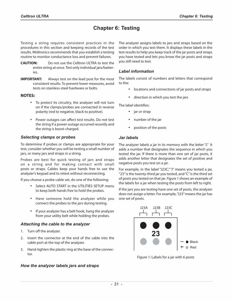
Jar labelsTheanalyzerlabelsajarinitsmemorywiththeletter“J.”Itadds a number that designates the sequence in which you tested the jar. If there is more than one set of jar posts, it adds another letter that designates the set of positive and negative posts you test on a jar.
Forexample, inthelabel“J23C,”“J”meansyoutesteda jar,“23”isthetwenty-thirdjaryoutested,and“C”isthethirdsetof posts you tested on that jar. Figure 1showsanexampleofthe labels for a jar when testing the posts from left to right.
If the jars you are testing have one set of posts, the analyzer doesnotassignaletter.Forexample,“J23”meansthejarhasone set of posts.
Chapter 6: TestingCelltron ULTRA
Chapter 6: Testing
Figure1:Labelsforajarwith6posts
J23CJ23BJ23A
• 32 •
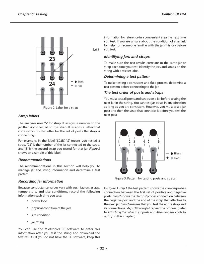
Strap labels
The analyzer uses “S” for strap. It assigns a number to the jar that is connected to the strap. It assigns a letter that corresponds to the letter for the set of posts the strap is connecting.
For example, in the label “S23B,” “S” means you tested astrap,“23”isthenumberofthejarconnectedtothestrap,and “B” is the second strap you tested for that jar. Figure 2 showsanexampleofthislabel.
RecommendationsThe recommendations in this section will help you to manage jar and string information and determine a test pattern.
Recording jar informationBecause conductance values vary with such factors as age, temperature, and site conditions, record the following information each time you test:
• power load
• physical condition of the jars
• site condition
• jar rating
You can use the Midtronics PC software to enter thisinformation after you test the string and download the test results. Ifyoudonothave thePCsoftware,keep this
informationforreferenceinaconvenientareathenexttimeyou test. If you are unsure about the condition of a jar, ask for help from someone familiar with the jar’s history before you test.
Identifying jars and strapsTo make sure the test results correlate to the same jar or strap each time you test, identify the jars and straps on the string with a sticker label.
Determining a test patternTomaketestingaconsistentandfluidprocess,determineatest pattern before connecting to the jar.
The test order of posts and strapsYoumusttestallpostsandstrapsonajarbeforetestingthenextjarinthestring.Youcantestjarpostsinanydirectionaslongasyouareconsistent.However,youmusttestajarpost and then the strap that connects it before you test the nextpost
In Figure 3, step 1thetestpatternshowstheclamps/probesconnection between the first set of positive and negative posts. Step 2showstheclamps/probesconnectionbetweenthe negative post and the end of the strap that attaches to thenextjar.Step 2 ensures that you test the entire strap and its connections. Steps 3 through 6 repeat the process. (Refer to Attaching the cable to jar posts and Attaching the cable to a strap in this chapter.)
Chapter 6: Testing Celltron ULTRA
Figure3:Patternfortestingpostsandstraps
S23B
Figure2:Labelforastrap

• 33 •
Chapter 6: TestingCelltron ULTRA
• 34 •
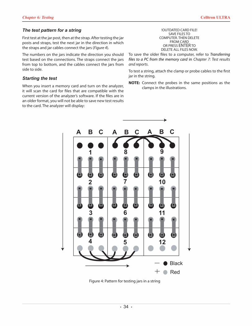
The test pattern for a stringFirst test at the jar post, then at the strap. After testing the jar postsandstraps,testthenextjarinthedirectioninwhichthe straps and jar cables connect the jars (Figure 4).
The numbers on the jars indicate the direction you should test based on the connections. The straps connect the jars from top to bottom, and the cables connect the jars from side to side.
Starting the testWhenyouinsertamemorycardandturnontheanalyzer,it will scan the card for files that are compatible with the current version of the analyzer’s software. If the files are in an older format, you will not be able to save new test results to the card. The analyzer will display:
!OUTDATEDCARDFILE!SAVEFILESTO
COMPUTER.THENDELETEFROMCARD
ORPRESSENTER TO DELETEALLFILESNOW.
To save the older files to a computer, refer to Transferring files to a PC from the memory card in Chapter 7: Test results and reports.
To test a string, attach the clamp or probe cables to the first jar in the string.
NOTE: Connect the probes in the same positions as the clamps in the illustrations.
Figure4:Patternfortestingjarsinastring
Chapter 6: Testing Celltron ULTRA
• 35 •
Guidelines• Do not place clamps or probes on stainless
steel hardware, such as bolt heads, washers, or threaded posts. Stainless steel hardware can yield low conductance values. If you have to test on stainless steel, record it in your testing records.
• The jars might have grease on the terminals and connections to prevent corrosion. You do nothave to wipe off the grease before attaching the clamps or connecting the probes.
• Test each jar in the same location or position. Changing the location of the test point might vary test results.
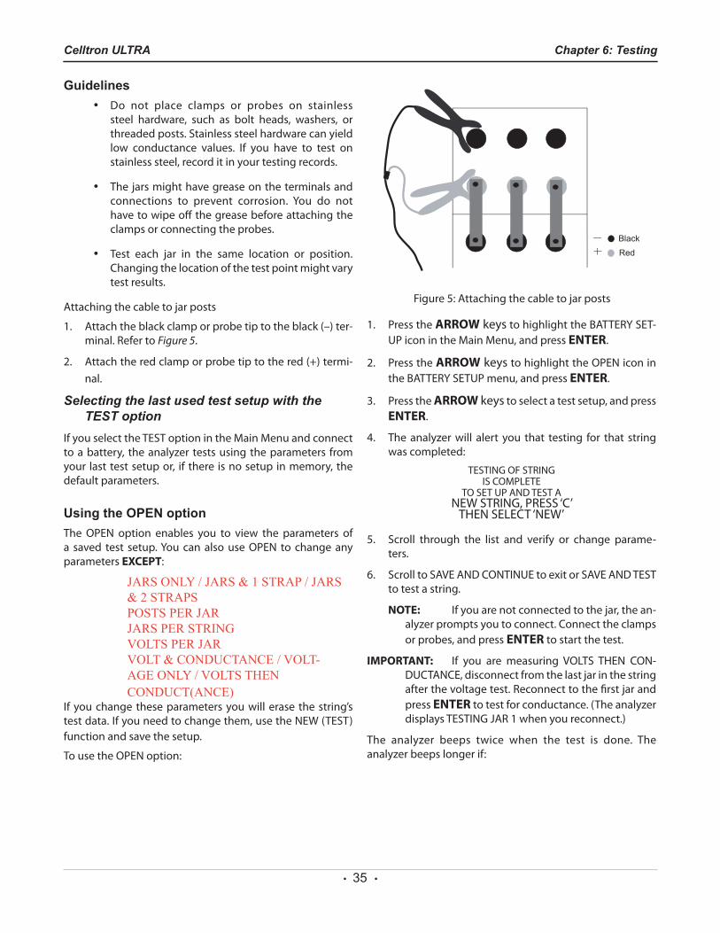
Attaching the cable to jar posts
1. Attachtheblackclamporprobetiptotheblack(–)ter-minal. Refer to Figure 5.
2. Attachtheredclamporprobetiptothered(+)termi-nal.
Selecting the last used test setup with the TEST option
IfyouselecttheTESToptionintheMainMenuandconnectto a battery, the analyzer tests using the parameters from your last test setup or, if there is no setup in memory, the default parameters.
Using the OPEN optionTheOPEN option enables you to view the parameters ofa saved test setup.YoucanalsouseOPEN to changeanyparameters EXCEPT:
JARS ONLY / JARS & 1 STRAP / JARS & 2 STRAPSPOSTS PER JARJARS PER STRINGVOLTS PER JARVOLT & CONDUCTANCE / VOLT-AGE ONLY / VOLTS THEN CONDUCT(ANCE)
If you change these parameters you will erase the string’s testdata.Ifyouneedtochangethem,usetheNEW(TEST)function and save the setup.
TousetheOPENoption:
1. PresstheARROW keystohighlighttheBATTERYSET-UPiconintheMainMenu,andpressENTER.
2. PresstheARROW keystohighlighttheOPENiconintheBATTERYSETUPmenu,andpressENTER.
3. PresstheARROW keys to select a test setup, and press ENTER.
4. Theanalyzerwill alert you that testing for that stringwas completed:
TESTINGOFSTRINGISCOMPLETE
TOSETUPANDTESTANEWSTRING,PRESS‘C’ THENSELECT‘NEW’
5. Scroll through the list and verify or change parame-ters.
6. ScrolltoSAVEANDCONTINUEtoexitorSAVEANDTESTto test a string.
NOTE: If you are not connected to the jar, the an-alyzer prompts you to connect. Connect the clamps or probes, and press ENTER to start the test.
IMPORTANT: If you are measuring VOLTS THEN CON-DUCTANCE,disconnectfromthelastjarinthestringafter the voltage test. Reconnect to the first jar and press ENTER to test for conductance. (The analyzer displaysTESTINGJAR1whenyoureconnect.)
The analyzer beeps twice when the test is done. The analyzer beeps longer if:
Figure 5: Attaching the cable to jar posts
Chapter 6: TestingCelltron ULTRA
• 36 •
• the conductance value is below the reference value
• the percentage of the reference is below the valuesforWARNorFAIL
• thevoltagelevelisbelowtheLOWVOLTSvalue
7. Afterreviewingthefirstsetofresults,chooseoneofthefollowing based on the type of testing you are doing:
• Ifyouaretestingjarsonly,testthenextsetofjarposts (if you have more than one set of posts), or testthenextjarinthestring.RefertoDetermining a test pattern in this chapter.
• If you are testing jars and straps, follow the steps in Attaching the cable to a strap in this chapter.
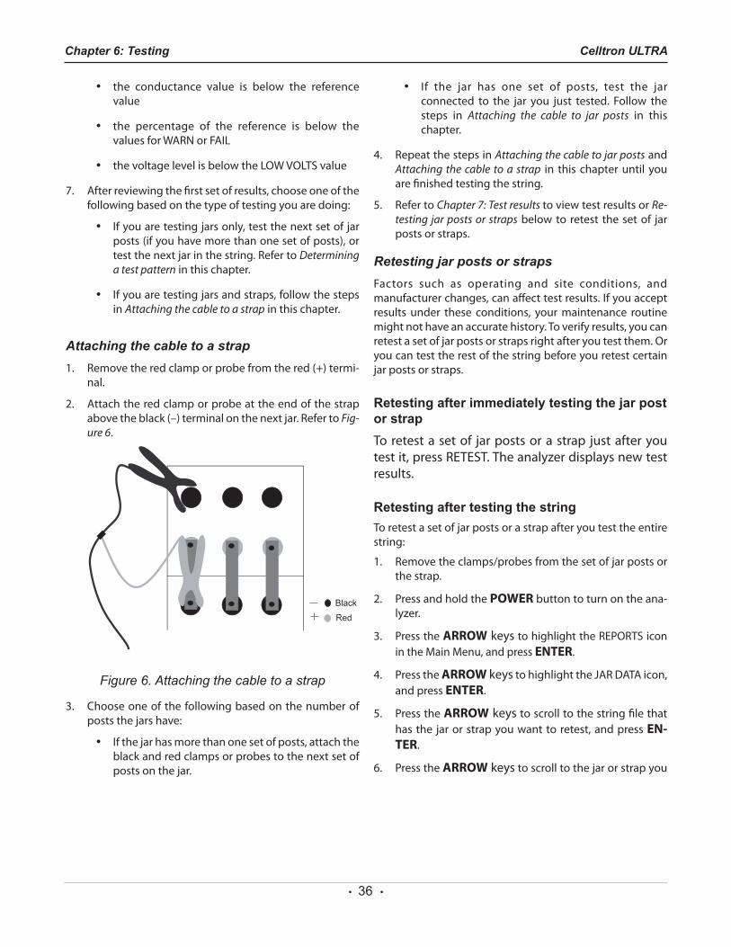
Attaching the cable to a strap1. Removetheredclamporprobefromthered(+)termi-
nal.
2. Attachtheredclamporprobeattheendofthestrapabovetheblack(–)terminalonthenextjar.RefertoFig-ure 6.
Figure 6. Attaching the cable to a strap
3. Choose one of the following based on the number of posts the jars have:
• If the jar has more than one set of posts, attach the blackandredclampsorprobestothenextsetofposts on the jar.
• If the jar has one set of posts, test the jar connected to the jar you just tested. Follow the steps in Attaching the cable to jar posts in this chapter.
4. RepeatthestepsinAttaching the cable to jar posts and Attaching the cable to a strap in this chapter until you are finished testing the string.
5. Refer to Chapter 7: Test results to view test results or Re-testing jar posts or straps below to retest the set of jar posts or straps.
Retesting jar posts or strapsFactors such as operating and site conditions, and manufacturer changes, can affect test results. If you accept results under these conditions, your maintenance routine might not have an accurate history. To verify results, you can retest a set of jar posts or straps right after you test them. Or you can test the rest of the string before you retest certain jar posts or straps.
Retesting after immediately testing the jar post or strapTo retest a set of jar posts or a strap just after you testit,pressRETEST.Theanalyzerdisplaysnewtestresults.
Retesting after testing the stringTo retest a set of jar posts or a strap after you test the entire string:
1. Removetheclamps/probesfromthesetofjarpostsorthe strap.
2. PressandholdthePOWER button to turn on the ana-lyzer.
3. PresstheARROW keystohighlighttheREPORTSiconin the Main Menu, and press ENTER.
4. PresstheARROW keystohighlighttheJARDATAicon,and press ENTER.
5. PresstheARROW keys to scroll to the string file that has the jar or strap you want to retest, and press EN-TER.
6. PresstheARROW keys to scroll to the jar or strap you
Chapter 6: Testing Celltron ULTRA
• 37 •
want to retest.
7. PresstheRETEST key.
8. After retesting, the analyzer will display the new results. To retest another jar or strap, scroll to it and press the RETEST key.
9. PresstheBACK key to end.
Adding a placeholder for a missing or dead jar/battery
You can create a placeholder for a dead ormiss ing batter y by us ing the ADD BATTERY optionintheREPORTSMENU.Therearetwowaystoaddaplaceholder.
NOTE: If you have selected JARS & 1 STRAP or JARS & 2STRAPSasthetestmode,youmustalsoaddaplace-holder for the strap.
When testing a string1. When theanalyzerdisplays the lastgood test results,
disconnect from the jar and press the BACK key to re-turntotheMainMenu.SelecttheTESTicon,andpressENTER.
2. Theanalyzerwilldisplaythefollowingscreen:
===WARNING=== CONNECTTO
JARXX REDLEADTOPOSITIVE POST,BLACKLEADTO
NEGATIVEPOST!PRESS‘5’TOADDJAR
NOTE: XXisthebatteryIDofthebatterywhoseplaceisbe-ing taken.
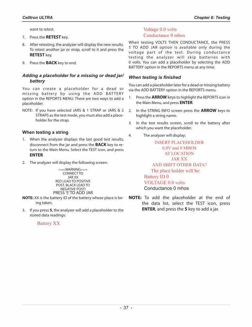
3. If you press 5, the analyzer will add a placeholder to the stored data readings:
Battery XX
Voltage 0.0 volts Conductance 0 mhos
When testing VOLTS THEN CONDUCTANCE, the PRESS5 TO ADD JAR option is available only during thevoltage par t of the test . During conductancetest ing the analyzer wi l l sk ip batter ies with 0 volts.You can add a placeholder by selecting the ADDBATTERYoptionintheREPORTSmenuatanytime.
When testing is finishedYoucanaddaplaceholderlaterforadeadormissingbatteryviatheADDBATTERYoptionintheREPORTSmenu.
1. PresstheARROW keystohighlighttheREPORTSiconinthe Main Menu, and press ENTER.
2. IntheSTRINGINFOscreenpressthe ARROW keys to highlight a string name.
3. In the test results screen, scroll to the battery after which you want the placeholder.
4. Theanalyzerwilldisplay:
INSERT PLACEHOLDER 0.0V and 0 MHOS
AT LOCATION JAR XX
AND SHIFT OTHER DATA?The place holder will be:
Battery ID 0VOLTAGE 0.0 voltsConductance 0 mhos
NOTE: To add the placeholder at the end of the data list, select the TEST icon, press ENTER, and press the 5 key to add a jar.
Chapter 6: TestingCelltron ULTRA

• 38 •
Chapter 6: Testing Celltron ULTRA

• 39 •
Chapter 6: TestingCelltron ULTRA
• 40 •
After you test a string, you can view and interpret test results, and archive the results to establish a maintenance history.
Viewing test resultsAfter you test a string, the analyzer saves the test results thataredisplayedonthescreen.Youcanviewtestresultsasmany times as you want until you delete the string.
String test resultsTo view a summary of averages, and high and low values:
1. PresstheARROW keystohighlighttheREPORTSiconinthe Main Menu, and press ENTER.
2. PresstheARROW keystohighlighttheSTRINGSUM-MARYicon,andpressENTER.
3. Press the ARROW keys to scroll a string name and press ENTER.
4. Thefirst screenof test results appears. Press theAR-ROW keys to move to the second screen and BACK again.
5. PressBACKtoexittotheREPORTSmenu.
Jar and strap test resultsTo view the test results for individual jars and straps that
were displayed as you tested the string:
1. PresstheARROW keystohighlighttheREPORTSiconinthe Main Menu, and press ENTER.
2. PresstheARROW keystohighlighttheJARDATAicon,and press ENTER.
3. Press theARROW keys to display results for all jars (andstraps,iftested)inthestring.Youcanretestjarsorstraps by pressing the RETEST key. See Retesting after testing the string in Chapter 6: Testing.
4. PresstheBACKkeytoexittotheREPORTSmenu.
The format and contents of printed and displayed test results differ slightly. See Interpreting test results in this chapter for an explanation of the test values and acomparison of formats.
For printing and archiving, see Archiving test results in this chapter.
Interpreting test results
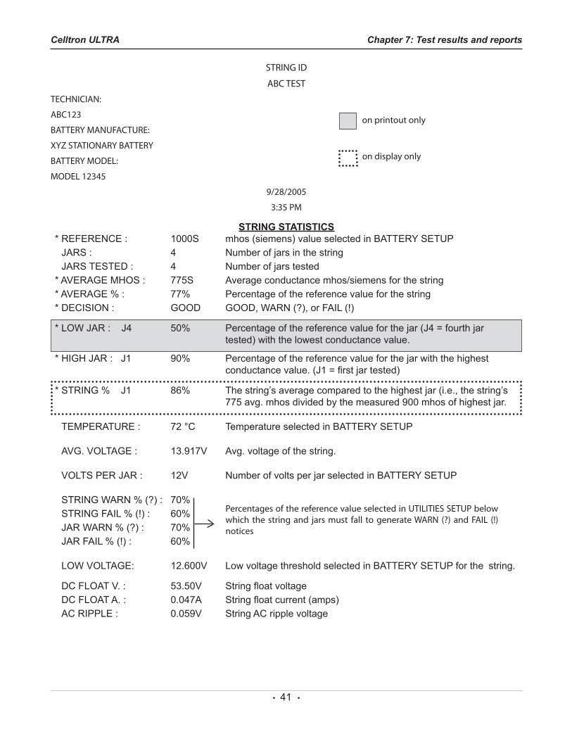
String summary (for a string of 12 V jars)ThetestresultsintheSTRINGSUMMARY(STRINGSTATISTICSon the printout) are averages for the jar posts and straps in the string. If you tested without a reference value, dashes appear inthe fieldsthataremarkedinthisexamplewithasterisks (*).
Chapter 7: Test results and reports Celltron ULTRA
Chapter 7: Test results and reports
• 41 •
STRINGID
ABCTEST
TECHNICIAN:
ABC123
BATTERYMANUFACTURE:
XYZSTATIONARYBATTERY
BATTERYMODEL:
MODEL12345
9/28/2005
3:35PM
STRING STATISTICS* REFERENCE : 1000S mhos (siemens) value selected in BATTERY SETUP
JARS : 4 Number of jars in the stringJARS TESTED : 4 Number of jars tested
* AVERAGE MHOS : 775S Average conductance mhos/siemens for the string* AVERAGE % : 77% Percentage of the reference value for the string* DECISION : GOOD GOOD, WARN (?), or FAIL (!)
* LOW JAR : J4 50% Percentage of the reference value for the jar (J4 = fourth jar tested) with the lowest conductance value.
* HIGH JAR : J1 90% Percentage of the reference value for the jar with the highest conductance value. (J1 = first jar tested)
* STRING % J1 86% The string’s average compared to the highest jar (i.e., the string’s 775 avg. mhos divided by the measured 900 mhos of highest jar.
TEMPERATURE : 72 °C Temperature selected in BATTERY SETUP
AVG. VOLTAGE : 13.917V Avg. voltage of the string.
VOLTS PER JAR : 12V Number of volts per jar selected in BATTERY SETUP
STRING WARN % (?) : 70% STRING FAIL % (!) : 60%JAR WARN % (?) : 70%JAR FAIL % (!) : 60%
LOW VOLTAGE: 12.600V Low voltage threshold selected in BATTERY SETUP for the string.
DC FLOAT V. : 53.50V String float voltageDC FLOAT A. : 0.047A String float current (amps)AC RIPPLE : 0.059V String AC ripple voltage
PercentagesofthereferencevalueselectedinUTILITIESSETUPbelowwhich thestringand jarsmust fall togenerateWARN (?)andFAIL (!)notices
on display only
on printout only
Chapter 7: Test results and reportsCelltron ULTRA
• 42 •
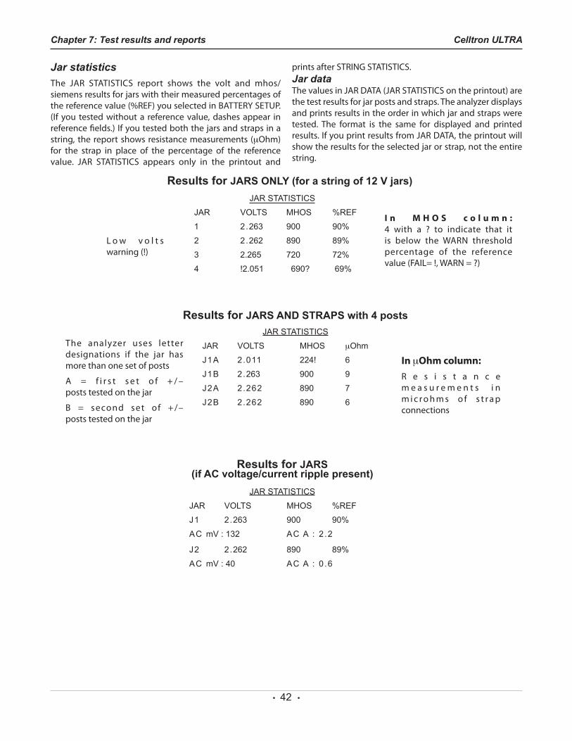
Jar statisticsThe JAR STATISTICS report shows the volt and mhos/siemens results for jars with their measured percentages of thereferencevalue(%REF)youselectedinBATTERYSETUP.(If you tested without a reference value, dashes appear in reference fields.) If you tested both the jars and straps in a string, the report shows resistance measurements (µOhm) for the strap in place of the percentage of the reference value. JAR STATISTICS appears only in the printout and
printsafterSTRINGSTATISTICS.Jar dataThevaluesinJARDATA(JARSTATISTICSontheprintout)arethe test results for jar posts and straps. The analyzer displays and prints results in the order in which jar and straps were tested. The format is the same for displayed and printed results.IfyouprintresultsfromJARDATA,theprintoutwillshow the results for the selected jar or strap, not the entire string.
L o w v o l t s warning(!)
I n M H O S c o l u m n : 4 with a ? to indicate that itis below the WARN thresholdpercentage of the reference value(FAIL=!,WARN=?)
The analyzer uses letter designations if the jar has more than one set of posts
A = f i r s t s e t o f + / – posts tested on the jar
B = second set of +/– posts tested on the jar
Results for JARS AND STRAPS with 4 posts
In µOhm column:R e s i s t a n c e m e a s u r e m e n t s i n m i c r o h m s o f s t r a p connections
JAR STATISTICS
JAR VOLTS MHOS %REF
1 2.263 900 90%
2 2.262 890 89%
3 2.265 720 72%
4 !2.051 690? 69%
JAR STATISTICS
JAR VOLTS MHOS µOhm
J1A 2.011 224! 6
J1B 2.263 900 9
J2A 2.262 890 7
J2B 2.262 890 6
Results for JARS (if AC voltage/current ripple present)
JAR STATISTICS
JAR VOLTS MHOS %REF
J1 2.263 900 90%
AC mV : 132 AC A : 2 .2
J2 2.262 890 89%
AC mV : 40 AC A : 0 .6
Results for JARS ONLY (for a string of 12 V jars)
Chapter 7: Test results and reports Celltron ULTRA
• 43 •
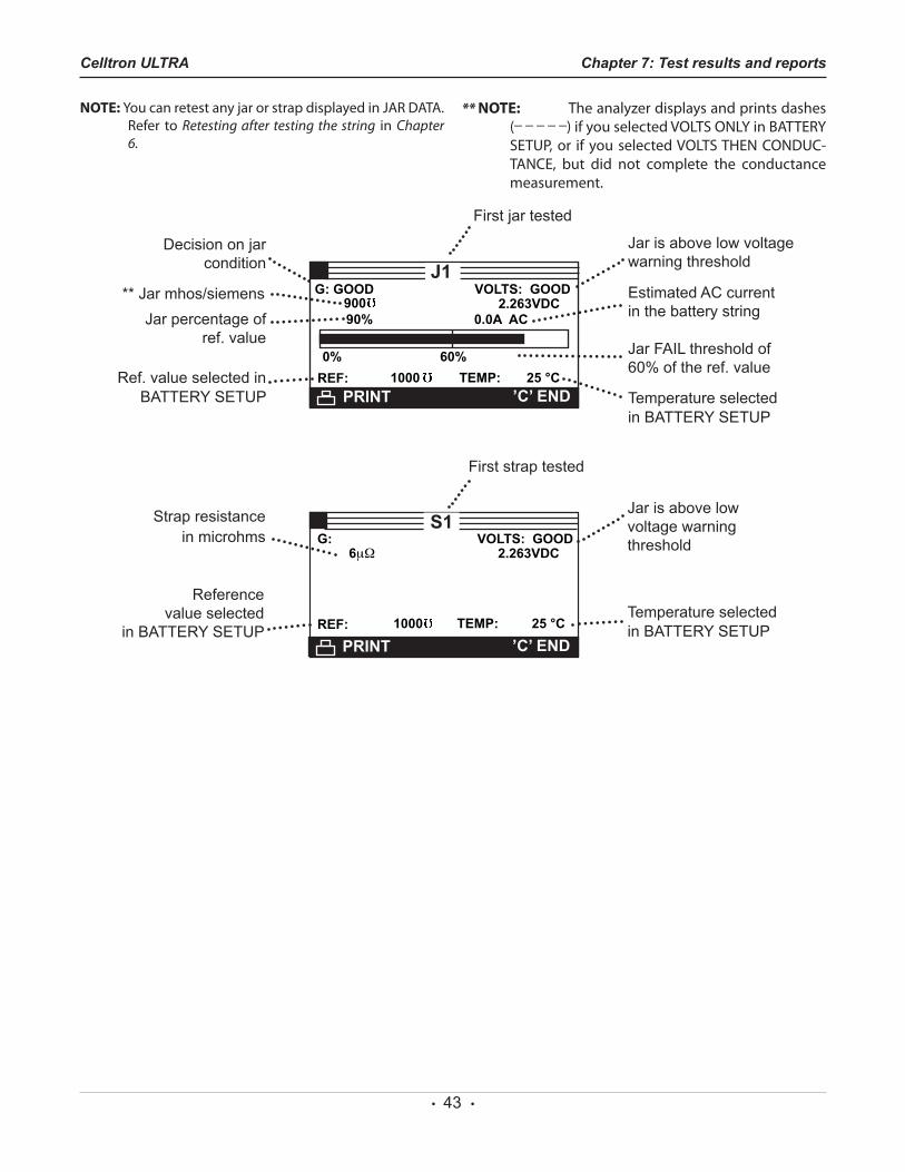
NOTE: YoucanretestanyjarorstrapdisplayedinJARDATA.Refer to Retesting after testing the string in Chapter 6.
** NOTE: The analyzer displays and prints dashes (_ _ _ _ _)ifyouselectedVOLTSONLYinBATTERYSETUP,or ifyouselectedVOLTSTHENCONDUC-TANCE, but did not complete the conductancemeasurement.
1
6µΩ
PRINT ’C’ END
G: VOLTS: GOOD2.263VDC
REF:
S1
1000 TEMP: 25 °C
Jar is above low voltage warning threshold
Strap resistance in microhms
Temperature selected in BATTERY SETUP
Reference value selected
in BATTERY SETUP
First strap tested
900
PRINT ’C’ END
G: GOOD VOLTS: GOOD
90%2.263VDC
0.0A AC
0% 60%REF:
J1
1000 TEMP: 25 °C
Jar is above low voltage warning threshold
Jar FAIL threshold of 60% of the ref. value
Jar percentage of ref. value
Temperature selected in BATTERY SETUP
Estimated AC current in the battery string
Decision on jar condition
** Jar mhos/siemens
Ref. value selected in BATTERY SETUP
First jar tested
Chapter 7: Test results and reportsCelltron ULTRA
• 44 •
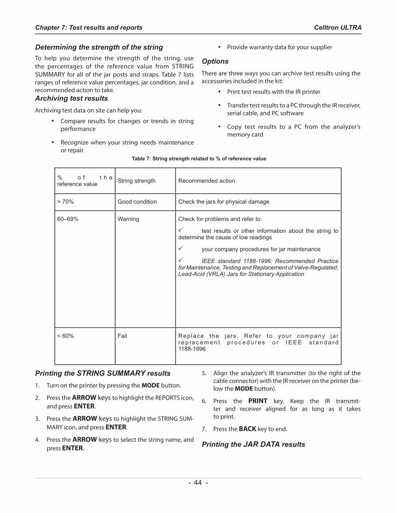
Determining the strength of the stringTo help you determine the strength of the string, use the percentages of the reference value from STRINGSUMMARY for all of the jarposts and straps.Table7 listsranges of reference value percentages, jar condition, and a recommended action to take.Archiving test resultsArchiving test data on site can help you:
• Compare results for changes or trends in string performance
• Recognize when your string needs maintenance or repair
• Providewarrantydataforyoursupplier
OptionsThere are three ways you can archive test results using the accessories included in the kit:
• PrinttestresultswiththeIRprinter
• TransfertestresultstoaPCthroughtheIRreceiver,serialcable,andPCsoftware
• Copy test results to a PC from the analyzer’smemory card
Table 7: String strength related to % of reference value
% o f t h e reference value String strength Recommended action
> 70% Good condition Check the jars for physical damage
60–69% Warning Check for problems and refer to:
test results or other information about the string to determine the cause of low readings
your company procedures for jar maintenance
IEEE standard 1188-1996: Recommended Practice for Maintenance, Testing and Replacement of Valve-Regulated, Lead-Acid (VRLA) Jars for Stationary Application
< 60% Fail Rep lace the ja rs . Refer to your company ja r r e p l a c e m e n t p r o c e d u r e s o r I E E E s t a n d a r d 1188-1996
Chapter 7: Test results and reports Celltron ULTRA
Printing the STRING SUMMARY results1. Turn on the printer by pressing the MODE button.
2. PresstheARROW keystohighlighttheREPORTSicon,and press ENTER.
3. PresstheARROW keystohighlighttheSTRINGSUM-MARYicon,andpressENTER.
4. PresstheARROW keys to select the string name, and press ENTER.
5. Align the analyzer’s IR transmitter (to the right of the cable connector) with the IR receiver on the printer (be-low the MODE button).
6. Press the PRINT key. Keep the IR transmit-ter and receiver aligned for as long as it takes to print.
7. PresstheBACK key to end.
Printing the JAR DATA results
• 45 •
1. Turn on the printer by pressing the MODE button.
2. PresstheARROW keystohighlighttheREPORTSicon,and press ENTER.
3. PresstheARROW keystohighlighttheJARDATAicon,and press ENTER.
4. PresstheARROW keys to select the string name, and press ENTER.
5. PresstheARROW keys to select a jar or strap screen, and press ENTER.
6. Align theanalyzer’s IR transmitter (to the rightof thecable connector) with the IR receiver on the printer (be-low the MODE button).
7. Press thePRINT key. Keep the IR transmitter and re-ceiver aligned for as long as it takes to print.
8. Repeat steps5, 6, and7 for each screen youwant toprint.
9. PresstheBACK key to end.
Transferring test results to a PC with the IR receiver (TRANSFER)
YoucantransferonefileatatimeorallfilessimultaneouslytoaPCwith the softwareand IR receiver included inthe kit.
After installing the software according to the installation instructions:
1. Press the ARROW keys to highlight the RE-PORTS icon in the Main Menu, and press ENTER.
2. Press the ARROW keys to highlight the TRANSFERiconintheREPORTSMENU,andpressENTER.
To transfer data for every string tested:
3. Align the analyzer’s IR transmitter (to the right of the cable connector) with the IR receiver.
4. PlaceacheckintheboxnexttoTRANSFERALLDATA,and press ENTER. The Main Menu appears when the transfer is complete.
To transfer data for a particular string:
3. Align the analyzer’s IR transmitter (to the right of the cable connector) with the IR receiver.
4. PlaceacheckintheboxnexttoSELECTFILE.Scrolltothe string name containing the test data you want to
transfer, and press ENTER. The data will take several seconds to transfer after which the Main Menu ap-pears.
Transferring files to a PC from the memory card
TheCelltronULTRAusesanSDmemorycardtostore testdata,which canbeuploaded to a PC.An SD card reader,which connects to a USB port, is included in the kit. The fileshave the extension .csv andopen inMicrosoft Excel.YoucanpurchaseSDmemorycardsatanyofficesupplyorcomputerstore.StartingwiththeRevisionHsoftware,theCelltronULTRAaccepts32MBto1Gcards.Largerstoragesizes are not compatible.
IMPORTANT: The memory card stores data as “read only.” To avoid corrupting the data on the card, do not remove the label and unlock the card to copy files from the PC.When you purchase a new SDcard, make sure its tab is in the locked position be-fore using. The Celltron ULTRA can read and write files when the card is in the locked position. Always keep the card’s tab in the locked position to prevent files frombeing corruptedby your PC’s operatingsystem. Format the card using the FORMAT option inBATTERYSETUPbeforeusing.
1. ConnectthecardreadertotheUSBportonthePC.
2. Insertthememorycardintothecardreader.
3. Save the files into a directory on your hard drive.
Additional options in the REPORTS menuInadditiontothetestdataoptions,theREPORTSmenuhastwo sources of information that are helpful in tracking the analyzer’s usage and software maintenance:
Counting the number of tests performed (TEST COUNTER)
The Celltron ULTRA automatically keeps track of the number oftestsperformed.SelecttheTESTCOUNTERiconandpressENTER to see the total number of tests performed since the analyzer was first used.
Finding the analyzer software VERSION Select theVERSION icon andpressENTER to display the serial numbers of the analyzer, cable, flashmemory, andEEPROMfirmwareversions.Theinformationwillbehelpfulwhen you call Midtronics for software updates, service, and parts.
Chapter 7: Test results and reportsCelltron ULTRA

• 46 •
Chapter 7: Test results and reports Celltron ULTRA

• 47 •
Chapter 7: Test results and reportsCelltron ULTRA
• 48 •
To use the Celltron ULTRA multimeter, press the ARROW keys to highlight the Dmm icon in the Main Menu, andpress ENTER.PresstheARROW keys to highlight one of the fourmeters in the DmmMenu, and pressENTER to select.PresstheBACK key when finished.
DC voltmeterTheDCvoltmetermeasuresfromreal-timeDCvoltagefrom0 to25Vdc.Thevoltmeterdisplays thevoltageasavaluewith an analog meter graphic.
AC voltmeterTheACvoltmetermeasuresreal-timeACvoltagefrom0to10Vac.Thevoltmeterdisplaysmillivoltsasavaluewithananalog meter graphic.
ScopeThe scope provides a real-time voltage trace with a range of 0to25Vdc.Scopeoptionsinclude:
1. Auto setup
Press1 to enable the scope to autorange.
2.Run/hold
Press2 to toggle between RUN mode (measure and display signal) or HOLD mode (freeze signal).
3.TimeDisplay
Press 3 to place the scope in time mode. The horizontalaxis is insecondsandtheverticalaxisis in volts.
4.FFTdisplay
Press 4 to place the scope in frequency mode. The horizontal axis is inhertz and thevertical axis isin volts.
CurrentConnect to the jar posts to estimate the AC ripple current through the jar.
Chapter 8: Digital Multimeter (Dmm) Celltron ULTRA
Chapter 8: Digital Multimeter (Dmm)
• 49 •
The troubleshooting tips in this section will help you resolve most testing and printing problems. For problems with the printer, digital temperature gun, or the PC softwareapplication, refer to their manuals or call Midtronics Customer Service for assistance. (See Patents, Limited Warranty, Service.)
Screen does not power on during testing (no text/graphics)
Check the connection to the jar.
The jar voltage might be too low (less than 1 volt) to test.
The analyzer’s battery pack might need to be recharged or replaced.
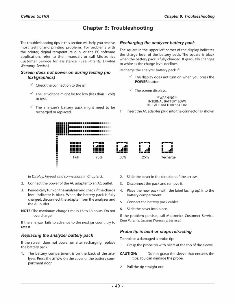
Recharging the analyzer battery packThe square in the upper left corner of the display indicates the charge level of the battery pack. The square is black when the battery pack is fully charged. It gradually changes to white as the charge level declines.
Recharge the analyzer battery pack if:
The display does not turn on when you press the POWER button.
The screen displays:
**WARNING** INTERNALBATTERYLOW!
REPLACEBATTERIESSOON!
1. Insert the AC adapter plug into the connector as shown
in Display, keypad, and connections in Chapter 2.
2. ConnectthepoweroftheACadaptertoanACoutlet.
3. Periodicallyturnontheanalyzerandcheckifthechargelevel indicator isblack.Whenthebatterypack is fullycharged, disconnect the adapter from the analyzer and the AC outlet.
NOTE:Themaximumchargetimeis16to18hours.Donotovercharge.
Iftheanalyzerfailstoadvancetothenextjarcount,trytoretest.
Replacing the analyzer battery packIf the screen does not power on after recharging, replace the battery pack.
1. The battery compartment is on the back of the ana-lyzer.Pressthearrow on the cover of the battery com-partment door.
2. Slidethecoverinthedirectionofthearrow.
3. Disconnectthepackandremoveit.
4. Placethenewpack(withthelabelfacingup)intothebattery compartment.
5. Connect the battery pack cables.
6. Slidethecoverintoplace.
If the problem persists, call Midtronics Customer Service. (See Patents, Limited Warranty, Service.)
Probe tip is bent or stops retractingTo replace a damaged a probe tip:
1. Grasptheprobetipwithpliersatthetopofthesleeve.
CAUTION: Donotgraspthesleevethatencasesthetips.Youcandamagetheprobe.
2. Pullthetipstraightout.
Full 75% 50% 25% Recharge
Chapter 9: TroubleshootingCelltron ULTRA
Chapter 9: Troubleshooting
• 50 •
3. Graspthereplacementtipwiththepliersandinsertitinto the sleeve.
4. Push the probe tip into a soft surface, such as card-board, until it hits the bottom of the sleeve.
NOTE: To obtain replacement tips, contact Midtronics Cus-tomer Service. (See Patents, Limited Warranty, Ser-vice.)
FILE NOT FOUNDIf the last file created, opened, or used does not match any files on the memory card, the analyzer will beep and display FILENOTFOUND.Theanalyzer’sinternalEEPROMmemorystores the last testused.When theanalyzerpowerson, itlooks for the last file used on the memory card. To prevent the message from reappearing when you turn on the analyzer,insertthecardcontainingthefile,openanexistingfile, or create a new file on the card.
Data is corrupt on the memory cardIf you are unable to select a string name, or the display shows garbled characters, the data on the card might be corrupt.TrytosalvagethefilesbycopyingthemtoyourPCusing the card reader included in the kit (USB port required). Reformat the memory card using the FORMAT option in the BATTERYSETUPmenu.Do not copy the files BACK to the memory card.
If the label has been removed, make sure the tab on the card is in the locked position. To avoid corrupting the data, donotunlockthecardtocopyfilesfromthePC.WhenyoupurchaseanewSDcard,placethetabinthelockedpositionbefore using.
Test results do not print or print incorrectly
STATUS LED
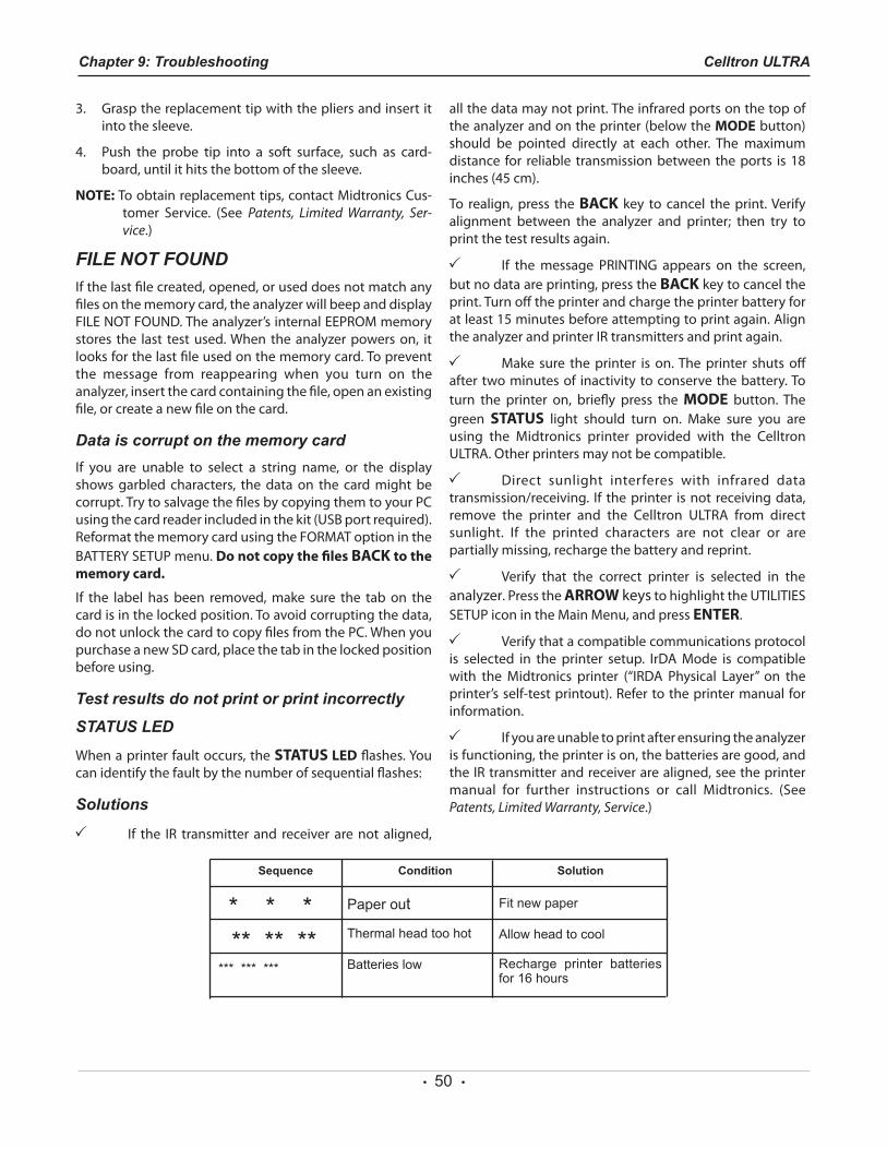
Whenaprinterfaultoccurs,theSTATUS LEDflashes.Youcanidentifythefaultbythenumberofsequentialflashes:
Solutions
If the IR transmitter and receiver are not aligned,
all the data may not print. The infrared ports on the top of the analyzer and on the printer (below the MODE button) should be pointed directly at each other. The maximumdistance for reliable transmission between the ports is 18 inches(45cm).
To realign, press the BACK key to cancel the print. Verify alignment between the analyzer and printer; then try to print the test results again.
If themessage PRINTING appears on the screen,but no data are printing, press the BACK key to cancel the print. Turn off the printer and charge the printer battery for at least 15 minutes before attempting to print again. Align the analyzer and printer IR transmitters and print again.
Make sure the printer is on. The printer shuts off after two minutes of inactivity to conserve the battery. To turn the printer on, briefly press the MODE button. The green STATUS light should turn on. Make sure you are using the Midtronics printer provided with the Celltron ULTRA. Other printers may not be compatible.
Direct sunlight interferes with infrared datatransmission/receiving. If theprinter isnot receivingdata,remove the printer and the Celltron ULTRA from direct sunlight. If the printed characters are not clear or are partially missing, recharge the battery and reprint.
Verify that the correct printer is selected in the analyzer.PresstheARROW keystohighlighttheUTILITIESSETUPiconintheMainMenu,andpressENTER.
Verify that a compatible communications protocol is selected in the printer setup. IrDAMode is compatiblewith theMidtronics printer (“IRDA Physical Layer” on theprinter’s self-test printout). Refer to the printer manual for information.
If you are unable to print after ensuring the analyzer is functioning, the printer is on, the batteries are good, and the IR transmitter and receiver are aligned, see the printer manual for further instructions or call Midtronics. (See Patents, Limited Warranty, Service.)
Chapter 9: Troubleshooting Celltron ULTRA
Sequence Condition Solution
Paper out
Thermal head too hot
Fit new paper
Allow head to cool
* * * ** ** **
*** *** *** Batteries low Recharge printer batteries for 16 hours

• 51 •
Chapter 9: TroubleshootingCelltron ULTRA
• 52 •
Model Number:CTU-6000(analyzer);CTU-6000KIT
Applications:Tests individual lead-acid cells or monoblocs (up to 16volts) in any common configuration
Voltage:1.5–20.0Vdc
Conductance:100–19,990siemens
Test Data Storage:500stringlocationsof480testresultsstoredinternally
Accuracy:±2%acrosstestrange
Voltmeter Resolution:5 mV
User Programmable Functions:•Presetvaluesforover250batterytypes
• Low voltage alarm setting
• Low conductance warning
• Low conductance failure
•Testmode(pushbutton/autostart)
Calibration:Auto-calibration before every test; no future calibration required
Connectorized Test Cable Options:•Dualcontactclamps
•Dualcontactprobes
• Custom cables by quotation
Power Requirements: 9.6 V, 1800 mAh, NiMH internal swappable battery andcharger
Display:
Specifications Celltron ULTRA
LCD—FSTN
66 .52 mm x 33 .25 mm (2 .62 in x 1 .31 in ) , 128x64pixels,40-degreeviewingangle,contrast ratio8,greenLEDbacklight
Keypad:Stainless-steel dome, polycarbonate overlay, 1,000,000actuations
Data Transfer:Infraredprotocol,half-duplexIrDAprotocol,RS-232printer,SDflashcard
Environmental Operating Range:0to+40˚C,95%relativehumidity,non-condensing
Storage Temperature: –20to82˚C
Over-Voltage Protection:•Auto-reset disconnect
• Reverse polarity protected
Housing Material:Acid resistant ABS plastic santoprene overmold
Analyzer Dimensions:2 8 0 m m x 1 0 5 m m x 8 0 m m (11inx4inx3in)
Case Dimensions:485mmx395mmx180mm
19inx15.5inx7in
Analyzer Weight: 1.18kg(2.6Ib)
CTU-6000 Kit Shipping Weight: Approximately5kg(11Ib)
Product Specifications
PatentsThe Celltron ULTRA Universal Stationary Battery Analyzer is made in the U.S.A. by Midtronics, Inc. and is protected by one or more of the following U.S. Patents: 6633165; 6623314; 6621272; 6597150; 6586941; 6566883; 6556019; 6544078; 6534993; 6507196; 6497209, 6495990; 6469511; 6466026; 6466025; 6465908; 6456045; 6445158; 6441585; 6437957; 6424158; 6417669; 6392414; 6377031; 6363303; 6359441; 6351102; 6332113; 6331762; 6329793; 6323650; 6316914; 6313608; 6313607; 6310481; 6304087; 6294897; 6294896; 6262563; 6259254; 6249124; 6225808; 6222369; 6172505; 6172483; 6163156; 6137269; 6104167; 6091245; 6081098; 6051976; 6037777; 6037751; 6002238; 5945829; 5914605; 5871858; 5831435; 5821756; 5757192; 5656920; 5598098; 5592093; 5589757; 5585728; 5583416; 5574355; 5572136; 5469043; 5343380; 5140269; 4912416; 4881038; 4825170; 4816768; 4322685; 3909708; 387391; and 387391. Other U.S. and Foreign patents issued and pending. This product may utilize technology exclusively licensed to Midtronics, Inc. by Johnson Controls, Inc. and/or Motorola, Inc.
Limited WarrantyThe Celltron ULTRA is warranted to be free of defects in materials and workmanship for a period of one year from date of purchase. Midtronics will, at our option, repair or replace the unit with a remanufactured unit. This limited warranty applies only to the Celltron ULTRA analyzer, and does not cover any other equipment, static damage, water damage, overvoltage damage, dropping the unit, or damage resulting from extraneous causes
including owner misuse. Midtronics is not liable for any incidental or consequential damages for breach of this warranty. The warranty is void if owner attempts to disassemble the unit or to modify the cable assembly.
ServiceTo obtain service, purchaser should contact Midtronics for a Return Authorization number, and return the unit to Midtronics freight prepaid, Attention: RA# ________. Midtronics will service the analyzer and reship the next scheduled business day following receipt, using the same type carrier and service as received. If Midtronics determines that the failure was caused by misuse, alteration, accident, or abnormal condition of operation or handling, purchaser will be billed for the repaired product and it will be returned freight prepaid with freight charges added to the invoice. Battery analyzer beyond the warranty period are subject to the repair charges in effect at that time. Optional remanufacturing service is available to return the tester to like-new condition. Out-of-warranty repairs will carry a 3-month warranty. Remanufactured units purchased from Midtronics are covered by a 6-month warranty.
www.midtronics.com
168-641F9/08 2008Midtronics,Inc.Allrightsreserved.
www.midtronics.com
Corporate Headquarters Willowbrook, IL USA Phone: 1.630.323.2800
Canadian Inquiries Toll Free: 1.866.592.8053
Midtronics b.v.European HeadquartersIJsselstein, The Netherlands Serving Europe, Africa, the Middle East, and The Netherlands Phone: +31 306 868 150
European Sales Locations IJsselstein, The Netherlands Paris, France Dusseldorf, Germany Midtronics China Office China Operations Shenzhen, China Phone: +86 755 8202 2037
Midtronics India Mumbai, India Phone: +91.989 237 6661
Asia/Pacific (excluding China) Contact Corporate Headquarters Phone: +1.630.323.2800
©2008 Midtronics, Inc. XXX-XXXA LG