Embed Size (px)
Citation preview
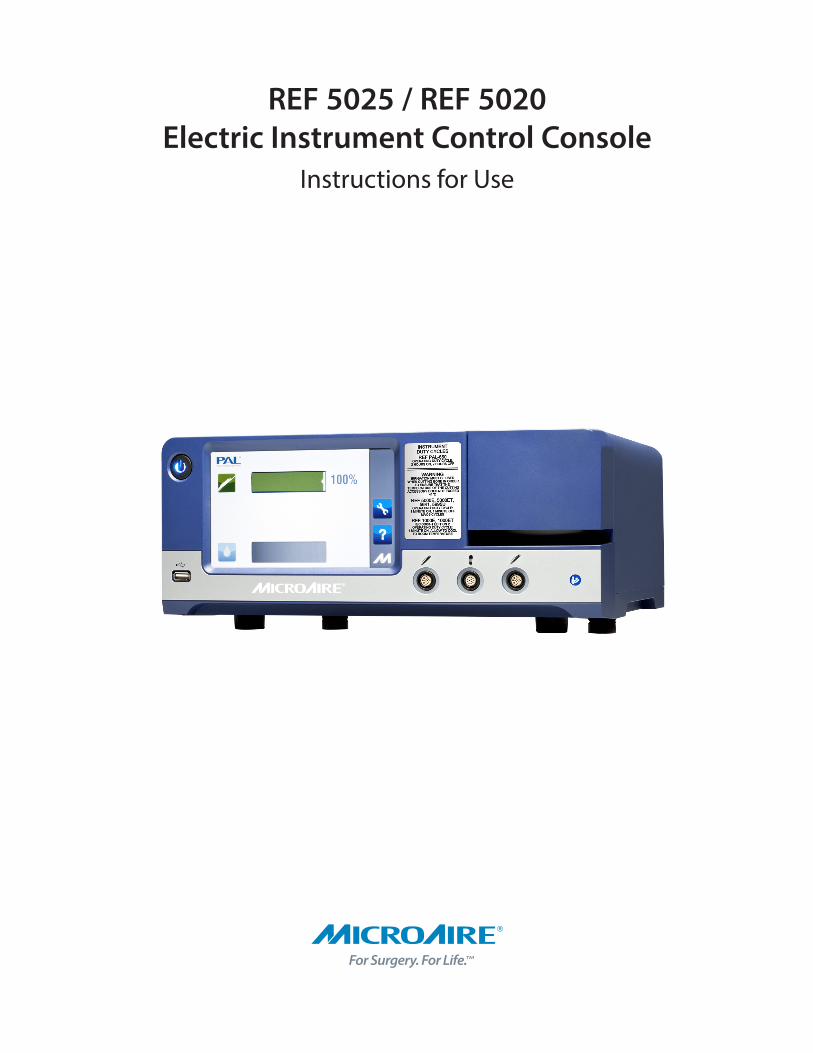
REF 5025 / REF 5020 Electric Instrument Control Console
Instructions for Use

1IM-5025 REV F 2020-05
The following additional languages are available online at www.microaire.com/resources:
Dansk (Danish)Danske oversættelser af denne brugsanvisning er tilgængelig online på www.microaire.com/resources.
Nederlands (Dutch)Nederlandse vertalingen van deze handleiding zijn online beschikbaar op www.microaire.com/resources.
Suomalainen (Finnish)Suomen käännökset tämän käyttöohjeen löytyvät osoitteesta www.microaire.com/resources.
Française (French)Des traductions françaises de ce manuel d’instructions sont disponibles en ligne à www.microaire.com/resources.
Deutsch (German)Deutsch Übersetzungen dieser Bedienungsanleitung sind online verfügbar unter www.microaire.com/resources.
Italiano (Italian)Traduzioni italiane di questo manuale sono disponibili online all’indirizzo www.microaire.com/resources.
Português (Portuguese)Tradução para português deste manual de instruções estão disponíveis online em www.microaire.com/resources.
Español (Spanish)Traducciones al español de este manual de instrucciones están disponibles en línea en www.microaire.com/resources.
Svenska (Swedish)Svenska översättningar av denna bruksanvisning finns tillgängliga online på www.microaire.com/resources.
Türk (Turkish)Bu kullanım kılavuzu Türkçe tercümeleri sitesinde online olarak mevcuttur www.microaire.com/resources.
中文(Chinese)本 明 的中文 本可在网上 www.microaire.com/resources.
Русский (Russian)Русские переводы этого руководства можно ознакомиться на сайте www.microaire.com/resources.
Português do Brasil (Brazilian)As traduções dinamarquesas deste manual estão disponíveis on-line em www.microaire.com/resources.
日本語 (Japanese)このマニュアルのデンマーク語の翻訳は、www.microaire.com/resources からオンラインで入手できます。.
Instrument Manual Translation Information
2 IM-5025 REV F 2020-05
Table of Contents
Instrument Manual Translation Information
Symbol Definition
Intended Use
Compatible Instruments
Warning, Caution and Note Definitions
System Setup
REF 5020 / REF 5025 Instrument Control Console Features
Connecting the Instruments
Loading Irrigation tubing
Tube holder repositioning
Connecting Foot Pedal Control
REF 5020 / REF 5025 Operation
Technical Description
Cleaning and Sterilization Guidelines
Environmental Parameters
Troubleshooting Guidelines
Maintenance Information
Proper Shipping, Storage and Handling
Essential Performance Statement
Electromagnetic Compatibility (EMC)
Warranty, Service, Repair and Disposal
1
3-5
5
5
5-8
8-12
8
9
10
11
11-12
13-22
23-24
24
24
25
26
26
26
26-28
29-30
3IM-5025 REV F 2020-05
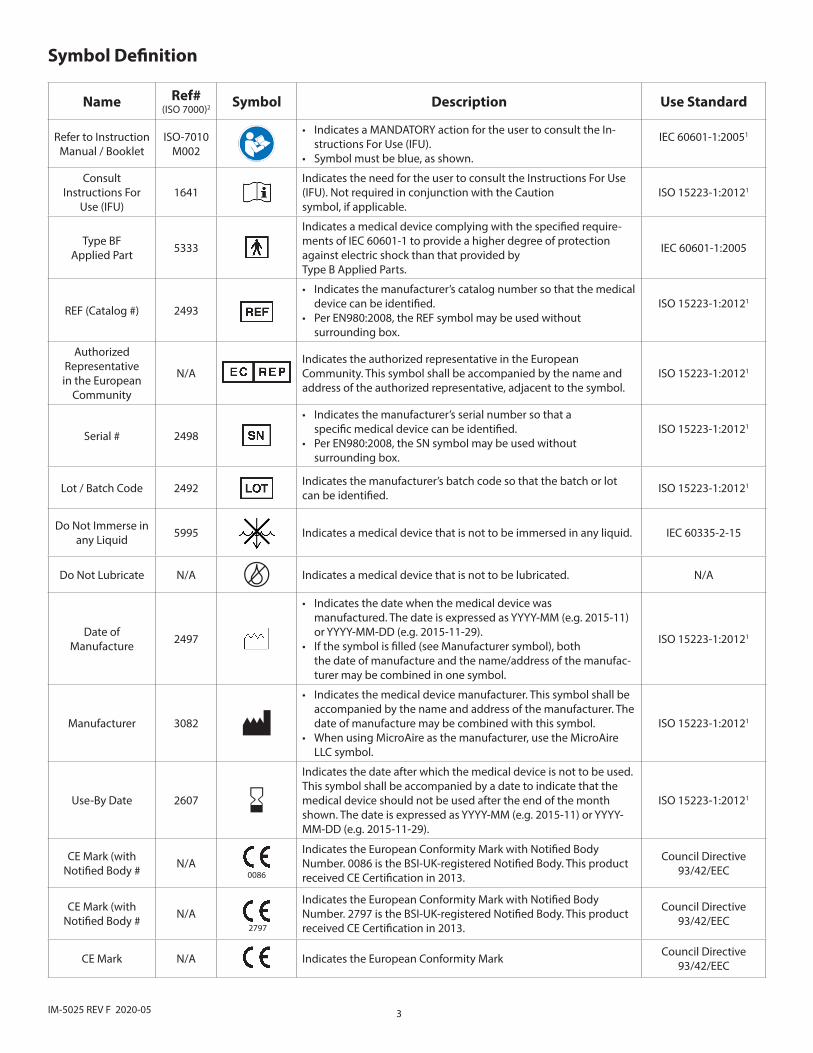
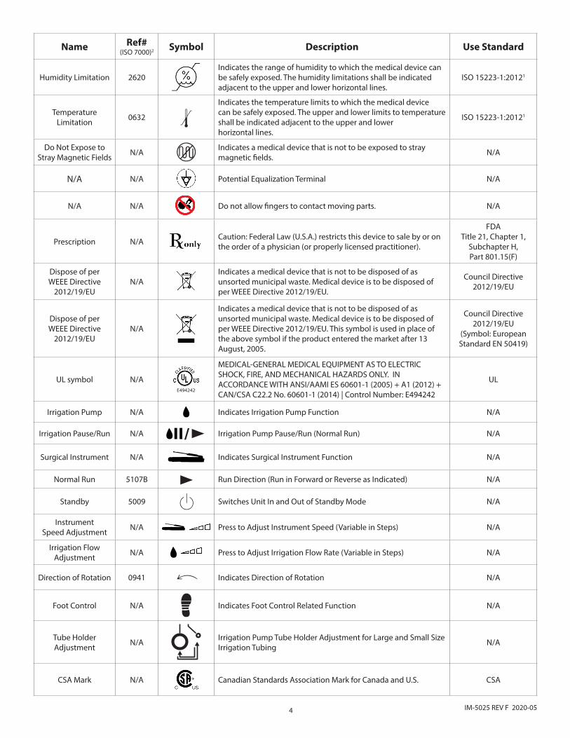
Symbol Definition
Name Ref#(ISO 7000)2 Symbol Description Use Standard
Refer to InstructionManual / Booklet
ISO-7010M002
• Indicates a MANDATORY action for the user to consult the In-structions For Use (IFU).
• Symbol must be blue, as shown.
IEC 60601-1:20051
Consult Instructions For
Use (IFU)1641
Indicates the need for the user to consult the Instructions For Use (IFU). Not required in conjunction with the Caution symbol, if applicable.
ISO 15223-1:20121
Type BFApplied Part 5333
Indicates a medical device complying with the specified require-ments of IEC 60601-1 to provide a higher degree of protection against electric shock than that provided byType B Applied Parts.
IEC 60601-1:2005
REF (Catalog #) 2493
• Indicates the manufacturer’s catalog number so that the medical device can be identified.
• Per EN980:2008, the REF symbol may be used without surrounding box.
ISO 15223-1:20121
AuthorizedRepresentativein the European
Community
N/AIndicates the authorized representative in the European Community. This symbol shall be accompanied by the name and address of the authorized representative, adjacent to the symbol.
ISO 15223-1:20121
Serial # 2498
• Indicates the manufacturer’s serial number so that a specific medical device can be identified.
• Per EN980:2008, the SN symbol may be used without surrounding box.
ISO 15223-1:20121
Lot / Batch Code 2492 Indicates the manufacturer’s batch code so that the batch or lot can be identified. ISO 15223-1:20121
Do Not Immerse in any Liquid 5995 Indicates a medical device that is not to be immersed in any liquid. IEC 60335-2-15
Do Not Lubricate N/A Indicates a medical device that is not to be lubricated. N/A
Date of Manufacture 2497
• Indicates the date when the medical device was manufactured. The date is expressed as YYYY-MM (e.g. 2015-11) or YYYY-MM-DD (e.g. 2015-11-29).
• If the symbol is filled (see Manufacturer symbol), both the date of manufacture and the name/address of the manufac-turer may be combined in one symbol.
ISO 15223-1:20121
Manufacturer 3082
• Indicates the medical device manufacturer. This symbol shall be accompanied by the name and address of the manufacturer. The date of manufacture may be combined with this symbol.
• When using MicroAire as the manufacturer, use the MicroAire LLC symbol.
ISO 15223-1:20121
Use-By Date 2607
Indicates the date after which the medical device is not to be used. This symbol shall be accompanied by a date to indicate that the medical device should not be used after the end of the month shown. The date is expressed as YYYY-MM (e.g. 2015-11) or YYYY-MM-DD (e.g. 2015-11-29).
ISO 15223-1:20121
CE Mark (with Notified Body # N/A
0086
Indicates the European Conformity Mark with Notified Body Number. 0086 is the BSI-UK-registered Notified Body. This product received CE Certification in 2013.
Council Directive93/42/EEC
CE Mark (with Notified Body # N/A
2797
Indicates the European Conformity Mark with Notified Body Number. 2797 is the BSI-UK-registered Notified Body. This product received CE Certification in 2013.
Council Directive93/42/EEC
CE Mark N/A Indicates the European Conformity Mark Council Directive93/42/EEC
4 IM-5025 REV F 2020-05
Name Ref#(ISO 7000)2 Symbol Description Use Standard
Humidity Limitation 2620Indicates the range of humidity to which the medical device can be safely exposed. The humidity limitations shall be indicatedadjacent to the upper and lower horizontal lines.
ISO 15223-1:20121
TemperatureLimitation 0632 >
Indicates the temperature limits to which the medical device can be safely exposed. The upper and lower limits to temperatureshall be indicated adjacent to the upper and lower horizontal lines.
ISO 15223-1:20121
Do Not Expose to Stray Magnetic Fields N/A Indicates a medical device that is not to be exposed to stray
magnetic fields. N/A
N/A N/A Potential Equalization Terminal N/A
N/A N/A Do not allow fingers to contact moving parts. N/A
Prescription N/A Caution: Federal Law (U.S.A.) restricts this device to sale by or on the order of a physician (or properly licensed practitioner).
FDATitle 21, Chapter 1,
Subchapter H,Part 801.15(F)
Dispose of perWEEE Directive
2012/19/EUN/A
Indicates a medical device that is not to be disposed of as unsorted municipal waste. Medical device is to be disposed of per WEEE Directive 2012/19/EU.
Council Directive2012/19/EU
Dispose of perWEEE Directive
2012/19/EUN/A
Indicates a medical device that is not to be disposed of as unsorted municipal waste. Medical device is to be disposed of per WEEE Directive 2012/19/EU. This symbol is used in place of the above symbol if the product entered the market after 13 August, 2005.
Council Directive2012/19/EU
(Symbol: EuropeanStandard EN 50419)
UL symbol N/AE494242
MEDICAL-GENERAL MEDICAL EQUIPMENT AS TO ELECTRIC SHOCK, FIRE, AND MECHANICAL HAZARDS ONLY. IN ACCORDANCE WITH ANSI/AAMI ES 60601-1 (2005) + A1 (2012) + CAN/CSA C22.2 No. 60601-1 (2014) | Control Number: E494242
UL
Irrigation Pump N/A Indicates Irrigation Pump Function N/A
Irrigation Pause/Run N/A /p Irrigation Pump Pause/Run (Normal Run) N/A
Surgical Instrument N/A Indicates Surgical Instrument Function N/A
Normal Run 5107B p Run Direction (Run in Forward or Reverse as Indicated) N/A
Standby 5009 X Switches Unit In and Out of Standby Mode N/A
Instrument Speed Adjustment N/A Press to Adjust Instrument Speed (Variable in Steps) N/A
Irrigation Flow Adjustment N/A Press to Adjust Irrigation Flow Rate (Variable in Steps) N/A
Direction of Rotation 0941 R Indicates Direction of Rotation N/A
Foot Control N/A Indicates Foot Control Related Function N/A
Tube Holder Adjustment N/A Irrigation Pump Tube Holder Adjustment for Large and Small Size
Irrigation Tubing N/A
CSA Mark N/A Canadian Standards Association Mark for Canada and U.S. CSA
5IM-5025 REV F 2020-05
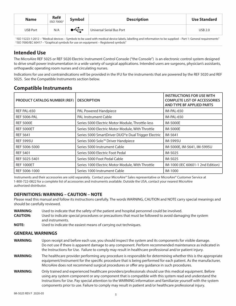
PRODUCT CATALOG NUMBER (REF) DESCRIPTION INSTRUCTIONS FOR USE WITH COMPLETE LIST OF ACCESSORIES AND TYPE BF APPLIED PARTS
REF PAL-650 PAL Powered Handpiece IM-PAL-650
REF 5006-PAL PAL Instrument Cable IM-PAL-650
REF 5000E Series 5000 Electric Motor Module, Throttle-less IM-5000E
REF 5000ET Series 5000 Electric Motor Module, With Throttle IM-5000E
REF 5641 Series 5000 SmartDriver DUO®e Dual Trigger Electric IM-5641
REF 5995U Series 5000 Solo™ Driver Handpiece IM-5995U
REF 5006-5000 Series 5000 Instrument Cable IM-5000E, IM-5641, IM-5995U
REF 5401 Series 5000 Electric Foot Pedal IM-5025
REF 5025-5401 Series 5000 Foot Pedal Cable IM-5025
REF 1000ET Series 1000 Electric Motor Module, With Throttle IM-1000 (IEC 60601-1 2nd Edition)
REF 5006-1000 Series 1000 Instrument Cable IM-1000
Instruments and their accessories are sold separately. Contact your MicroAire® Sales representative or MicroAire® Customer Service at 1-800-722-0822 for a complete list of accessories and instruments available. Outside the USA, contact your nearest MicroAire authorized distributor.
Compatible Instruments
DEFINITIONS: WARNING – CAUTION – NOTEPlease read this manual and follow its instructions carefully. The words WARNING, CAUTION and NOTE carry special meanings and should be carefully reviewed.
WARNING: Used to indicate that the safety of the patient and hospital personnel could be involved.CAUTION: Used to indicate special procedures or precautions that must be followed to avoid damaging the system and instruments.NOTE: Used to indicate the easiest means of carrying out techniques.
GENERAL WARNINGSWARNING: Upon receipt and before each use, you should inspect the system and its components for visible damage. Do not use if there is apparent damage to any component. Perform recommended maintenance as indicated in the Instructions for Use. Failure to comply may result in healthcare professional and/or patient injury.
WARNING: The healthcare provider performing any procedure is responsible for determining whether this is the appropriate equipment/instrument for the specific procedure that is being performed for each patient. As the manufacturer, MicroAire does not recommend surgical procedures or offer any guidance in such procedures.
WARNING: Only trained and experienced healthcare providers/professionals should use this medical equipment. Before using any system component or any component that is compatible with this system read and understand the Instructions for Use. Pay special attention to the WARNING information and familiarize yourself with the system components prior to use. Failure to comply may result in patient and/or healthcare professional injury.
The MicroAire REF 5025 or REF 5020 Electric Instrument Control Console (“the Console”) is an electronic control system designed to drive small power instrumentation in a wide variety of surgical applications. Intended users are surgeons, physician’s assistants, orthopaedic operating room nurses and circulating nurses.
Indications for use and contraindications will be provided in the IFU for the instruments that are powered by the REF 5020 and REF 5025. See the Compatible Instruments section below.
Intended Use
Name Ref#(ISO 7000)2 Symbol Description Use Standard
USB Port N/A Universal Serial Bus Port USB 2.0
1 ISO 15223-1:2012 – “Medical devices – Symbols to be used with medical device labels, labelling and information to be supplied – Part 1: General requirements”2 ISO 7000/IEC 60417 – “Graphical symbols for use on equipment – Registered symbols”
6 IM-5025 REV F 2020-05
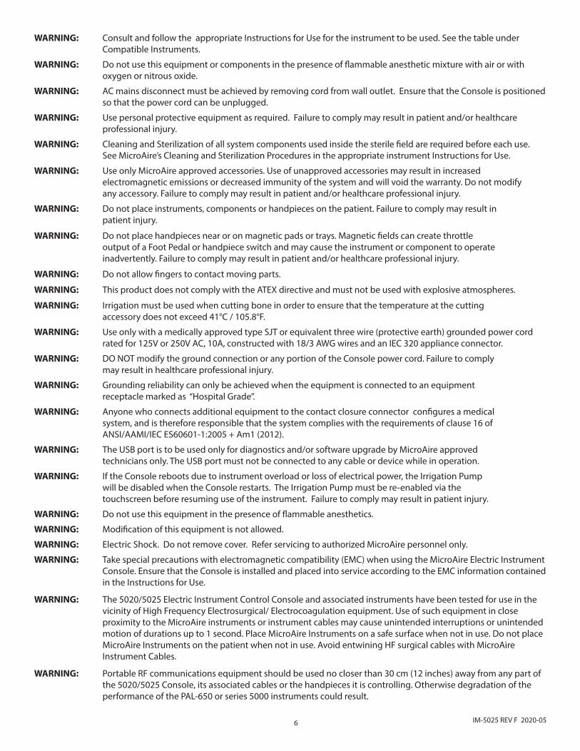
WARNING: Consult and follow the appropriate Instructions for Use for the instrument to be used. See the table under Compatible Instruments.
WARNING: Do not use this equipment or components in the presence of flammable anesthetic mixture with air or with oxygen or nitrous oxide.
WARNING: AC mains disconnect must be achieved by removing cord from wall outlet. Ensure that the Console is positioned so that the power cord can be unplugged.
WARNING: Use personal protective equipment as required. Failure to comply may result in patient and/or healthcare professional injury.
WARNING: Cleaning and Sterilization of all system components used inside the sterile field are required before each use. See MicroAire’s Cleaning and Sterilization Procedures in the appropriate instrument Instructions for Use.
WARNING: Use only MicroAire approved accessories. Use of unapproved accessories may result in increased electromagnetic emissions or decreased immunity of the system and will void the warranty. Do not modify any accessory. Failure to comply may result in patient and/or healthcare professional injury.
WARNING: Do not place instruments, components or handpieces on the patient. Failure to comply may result in patient injury.
WARNING: Do not place handpieces near or on magnetic pads or trays. Magnetic fields can create throttle output of a Foot Pedal or handpiece switch and may cause the instrument or component to operate inadvertently. Failure to comply may result in patient and/or healthcare professional injury.
WARNING: Do not allow fingers to contact moving parts.
WARNING: This product does not comply with the ATEX directive and must not be used with explosive atmospheres.
WARNING: Irrigation must be used when cutting bone in order to ensure that the temperature at the cutting accessory does not exceed 41°C / 105.8°F.
WARNING: Use only with a medically approved type SJT or equivalent three wire (protective earth) grounded power cord rated for 125V or 250V AC, 10A, constructed with 18/3 AWG wires and an IEC 320 appliance connector.
WARNING: DO NOT modify the ground connection or any portion of the Console power cord. Failure to comply may result in healthcare professional injury.
WARNING: Grounding reliability can only be achieved when the equipment is connected to an equipment receptacle marked as “Hospital Grade”.
WARNING: Anyone who connects additional equipment to the contact closure connector configures a medical system, and is therefore responsible that the system complies with the requirements of clause 16 of ANSI/AAMI/IEC ES60601-1:2005 + Am1 (2012).
WARNING: The USB port is to be used only for diagnostics and/or software upgrade by MicroAire approved technicians only. The USB port must not be connected to any cable or device while in operation.
WARNING: If the Console reboots due to instrument overload or loss of electrical power, the Irrigation Pump will be disabled when the Console restarts. The Irrigation Pump must be re-enabled via the touchscreen before resuming use of the instrument. Failure to comply may result in patient injury.
WARNING: Do not use this equipment in the presence of flammable anesthetics.
WARNING: Modification of this equipment is not allowed.
WARNING: Electric Shock. Do not remove cover. Refer servicing to authorized MicroAire personnel only.
WARNING: Take special precautions with electromagnetic compatibility (EMC) when using the MicroAire Electric Instrument Console. Ensure that the Console is installed and placed into service according to the EMC information contained in the Instructions for Use.
WARNING: The 5020/5025 Electric Instrument Control Console and associated instruments have been tested for use in the vicinity of High Frequency Electrosurgical/ Electrocoagulation equipment. Use of such equipment in close proximity to the MicroAire instruments or instrument cables may cause unintended interruptions or unintended motion of durations up to 1 second. Place MicroAire Instruments on a safe surface when not in use. Do not place MicroAire Instruments on the patient when not in use. Avoid entwining HF surgical cables with MicroAire Instrument Cables.
WARNING: Portable RF communications equipment should be used no closer than 30 cm (12 inches) away from any part of the 5020/5025 Console, its associated cables or the handpieces it is controlling. Otherwise degradation of the performance of the PAL-650 or series 5000 instruments could result.
7IM-5025 REV F 2020-05
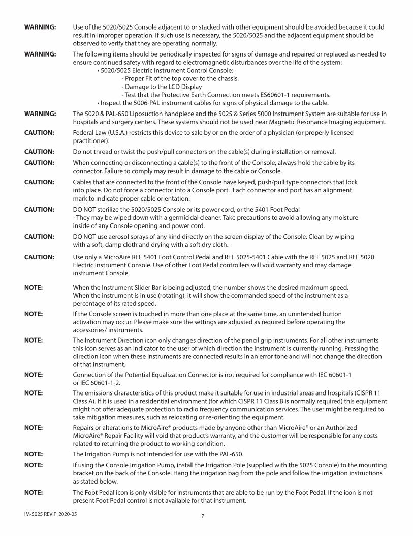
WARNING: Use of the 5020/5025 Console adjacent to or stacked with other equipment should be avoided because it could result in improper operation. If such use is necessary, the 5020/5025 and the adjacent equipment should be observed to verify that they are operating normally.
WARNING: The following items should be periodically inspected for signs of damage and repaired or replaced as needed to ensure continued safety with regard to electromagnetic disturbances over the life of the system: • 5020/5025 Electric Instrument Control Console: - Proper Fit of the top cover to the chassis. - Damage to the LCD Display - Test that the Protective Earth Connection meets ES60601-1 requirements. • Inspect the 5006-PAL instrument cables for signs of physical damage to the cable.
WARNING: The 5020 & PAL-650 Liposuction handpiece and the 5025 & Series 5000 Instrument System are suitable for use in hospitals and surgery centers. These systems should not be used near Magnetic Resonance Imaging equipment.
CAUTION: Federal Law (U.S.A.) restricts this device to sale by or on the order of a physician (or properly licensed practitioner).
CAUTION: Do not thread or twist the push/pull connectors on the cable(s) during installation or removal.
CAUTION: When connecting or disconnecting a cable(s) to the front of the Console, always hold the cable by its connector. Failure to comply may result in damage to the cable or Console.
CAUTION: Cables that are connected to the front of the Console have keyed, push/pull type connectors that lock into place. Do not force a connector into a Console port. Each connector and port has an alignment mark to indicate proper cable orientation.
CAUTION: DO NOT sterilize the 5020/5025 Console or its power cord, or the 5401 Foot Pedal - They may be wiped down with a germicidal cleaner. Take precautions to avoid allowing any moisture inside of any Console opening and power cord.
CAUTION: DO NOT use aerosol sprays of any kind directly on the screen display of the Console. Clean by wiping with a soft, damp cloth and drying with a soft dry cloth.
CAUTION: Use only a MicroAire REF 5401 Foot Control Pedal and REF 5025-5401 Cable with the REF 5025 and REF 5020 Electric Instrument Console. Use of other Foot Pedal controllers will void warranty and may damage instrument Console.
NOTE: When the Instrument Slider Bar is being adjusted, the number shows the desired maximum speed. When the instrument is in use (rotating), it will show the commanded speed of the instrument as a percentage of its rated speed.NOTE: If the Console screen is touched in more than one place at the same time, an unintended button activation may occur. Please make sure the settings are adjusted as required before operating the accessories/ instruments.NOTE: The Instrument Direction icon only changes direction of the pencil grip instruments. For all other instruments this icon serves as an indicator to the user of which direction the instrument is currently running. Pressing the direction icon when these instruments are connected results in an error tone and will not change the direction of that instrument.NOTE: Connection of the Potential Equalization Connector is not required for compliance with IEC 60601-1 or IEC 60601-1-2.NOTE: The emissions characteristics of this product make it suitable for use in industrial areas and hospitals (CISPR 11 Class A). If it is used in a residential environment (for which CISPR 11 Class B is normally required) this equipment might not offer adequate protection to radio frequency communication services. The user might be required to take mitigation measures, such as relocating or re-orienting the equipment.NOTE: Repairs or alterations to MicroAire® products made by anyone other than MicroAire® or an Authorized MicroAire® Repair Facility will void that product’s warranty, and the customer will be responsible for any costs related to returning the product to working condition.NOTE: The Irrigation Pump is not intended for use with the PAL-650.
NOTE: If using the Console Irrigation Pump, install the Irrigation Pole (supplied with the 5025 Console) to the mounting bracket on the back of the Console. Hang the irrigation bag from the pole and follow the irrigation instructions as stated below.
NOTE: The Foot Pedal icon is only visible for instruments that are able to be run by the Foot Pedal. If the icon is not present Foot Pedal control is not available for that instrument.

8 IM-5025 REV F 2020-05
Standby ButtonBlinking when in stand by , must press and hold to power up
Foot Pedal Connector(Not used with PAL-650)
Handpiece connectorsAllows connection and running of handpieces simultaneously
USB Serial PortCommunication port used for software upgrade(s)
Irrigation Pump (Not used with PAL-650)Color Touch Screen
Touch screen to control settings
FIGURE 1
Power ReceptacleConnect Console power cord and connect to facility power outlet
Irrigation Bag Pole-Mounting Bracket(Not used with PAL-650)
Contact ClosureUsed for control of MicroAire- compatible suction pumps
Potential Equalization ConnectorUsed for common ground among multiple instruments in procedure
FIGURE 2
REF 5020 / REF 5025 Instrument Control Console Features
Sytem Setup
NOTE: Foot Pedal can only control one instrument at a time. If the Foot Pedal is active for Instrument 1 and you wish to change to Instrument 2, make sure that neither connected instrument is running, then press the Foot Pedal icon on the instrument of your choice to activate the Foot Pedal for that instrument.
NOTE: MicroAire® mailing address information is located on the back cover of this Instructions for Use document.
NOTE: DO NOT return equipment without an RMA number. Doing so could cause delays in service, and/or problems tracking your equipment.

9IM-5025 REV F 2020-05
WARNING: Do not place instruments, components or handpieces on the patient. Failure to comply may result in patient injury.
WARNING: Do not place handpieces near or on magnetic pads or trays. Magnetic fields can create throttle output of a Foot Pedal or handpiece switch and may cause the instrument or component to operate inadvertently. Failure to comply may result in patient and/or healthcare professional injury.
1. Place the Console on a sturdy, flat surface near a hospital-grade outlet.
2. Install the power cord plug into the power receptacle on the Console.
3. Install the other end of the power cord into a hospital wall outlet.
4. Wait for the Console to initialize, then press and hold the blinking standby button to turn on the Console.
5. If using a Foot Pedal, plug the Foot Pedal cable into the port marked with a Foot Pedal symbol. Align the marks and gently push the connectors together. Once correctly plugged in, the blue led light around the connector will light up. Only one Foot Pedal may be connected to the Console at a time, but can be selected to operate either of the Foot Pedal-compatible instruments.
6. Plug the handpiece cable(s) into the Console port(s) marked with a HANDPIECE symbol. Align the marks and gently push the connectors together. Once correctly plugged in, the blue led light around the connector will light up. Two handpieces may be connected to the Console and operated simultaneously.
7. Plug the other end of the handpiece cable(s) into the instrument(s). See Instructions For Use supplied with each handpiece for connection information.
8. Attach the cutting accessory to the handpiece(s). See the Instructions for Use supplied with each handpiece or attachment for cutting accessory installation information.
9. If required, install the irrigation tubing into the Console Irrigation Pump by following the instructions in the “Irrigation Settings” section in the Instructions for Use manual.
Instrument Duty Cycles• The REF 5020 & REF 5025 Electric Instrument Control Consoles are designed for Continuous Operation. Each Instrument has its own Duty Cycle.
• The REF PAL-650 has an operating duty cycle of 2 hours ON, 2 hours OFF.
• The REF 5000E, 5000ET, 5641 and 5995-U instruments have an operating duty cycle of 1 minute ON, 1 minute OFF, for 6 cycles maximum.
• The REF 1000E and 1000ET instruments are designed to operate for 1 minute of continuous use and should be allowed to cool to room temperature. (IEC 60601-1 2nd Edition)
WARNING: Irrigation must be used when cutting bone in order to ensure that the temperature at the cutting accessory does not exceed 41°C / 105.8°F.
NOTE: If using the Console Irrigation Pump, install the Irrigation Pole (supplied with the 5025 Console) to the mounting bracket on the back of the Console. Hang the irrigation bag from the pole and follow the irrigation instructions as stated below.
CAUTIONS:
• Do not thread or twist the push/pull connectors on the cable(s) during installation or removal.
• When connecting or disconnecting a cable(s) to the front of the Console, always hold the cable by its connector. Failure to comply may result in damage to the cable or Console.
• Cables that are connected to the front of the Console have keyed, push/pull type connectors that lock into place. Do not force a connector into a Console port. Each connector and port has an alignment mark to indicate proper cable orientation.
Connecting the Instruments
10 IM-5025 REV F 2020-05
Load the section of tubing between the two connectors into the Irrigation Pump to prevent tubing from advancing inadvertently
æ å
Tube Loading AreaBetween two arrows
FIGURE 4
5Insert spike into bag by slightly twisting the bag spike while penetrating the irrigation bag as shown
1 Open irrigation area door
4
3
2
This end of the irrigation tubing will disperse the irrigation fluid
Load Irrigation tubingmaking note of the pump direction (See notes 1-3)
To close Irrigator Pump door, push down on the door until it snaps into place
NOTE: This end of the irrigation tubing will be connected to the irrigation bag
6
Open Irrigator Pump door by lifting the door as shown
FIGURE 3
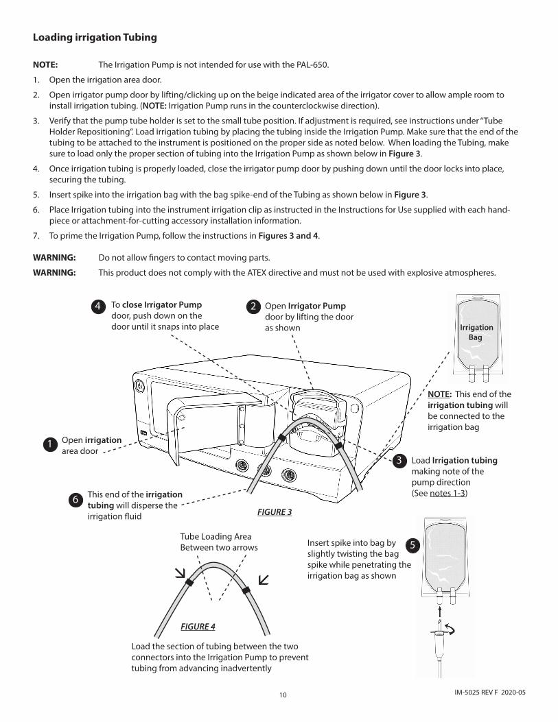
Loading irrigation Tubing
NOTE: The Irrigation Pump is not intended for use with the PAL-650.
1. Open the irrigation area door.
2. Open irrigator pump door by lifting/clicking up on the beige indicated area of the irrigator cover to allow ample room to install irrigation tubing. (NOTE: Irrigation Pump runs in the counterclockwise direction).
3. Verify that the pump tube holder is set to the small tube position. If adjustment is required, see instructions under “Tube Holder Repositioning”. Load irrigation tubing by placing the tubing inside the Irrigation Pump. Make sure that the end of the tubing to be attached to the instrument is positioned on the proper side as noted below. When loading the Tubing, make sure to load only the proper section of tubing into the Irrigation Pump as shown below in Figure 3.
4. Once irrigation tubing is properly loaded, close the irrigator pump door by pushing down until the door locks into place, securing the tubing.
5. Insert spike into the irrigation bag with the bag spike-end of the Tubing as shown below in Figure 3.
6. Place Irrigation tubing into the instrument irrigation clip as instructed in the Instructions for Use supplied with each hand-piece or attachment-for-cutting accessory installation information.
7. To prime the Irrigation Pump, follow the instructions in Figures 3 and 4.
WARNING: Do not allow fingers to contact moving parts.
WARNING: This product does not comply with the ATEX directive and must not be used with explosive atmospheres.
Irrigation Bag
11IM-5025 REV F 2020-05
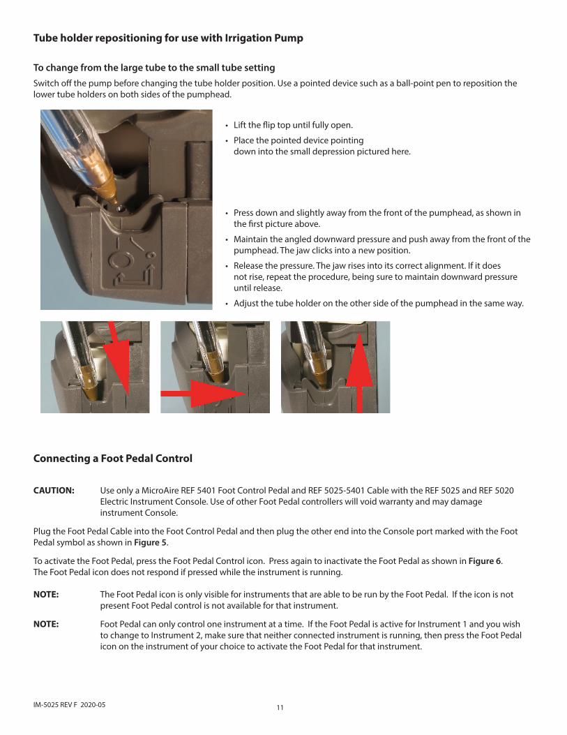
Tube holder repositioning for use with Irrigation Pump
To change from the large tube to the small tube settingSwitch off the pump before changing the tube holder position. Use a pointed device such as a ball-point pen to reposition the lower tube holders on both sides of the pumphead.
• Lift the flip top until fully open.
• Place the pointed device pointing down into the small depression pictured here.
• Press down and slightly away from the front of the pumphead, as shown in the first picture above.
• Maintain the angled downward pressure and push away from the front of the pumphead. The jaw clicks into a new position.
• Release the pressure. The jaw rises into its correct alignment. If it does not rise, repeat the procedure, being sure to maintain downward pressure until release.
• Adjust the tube holder on the other side of the pumphead in the same way.
Connecting a Foot Pedal Control
CAUTION: Use only a MicroAire REF 5401 Foot Control Pedal and REF 5025-5401 Cable with the REF 5025 and REF 5020 Electric Instrument Console. Use of other Foot Pedal controllers will void warranty and may damage instrument Console.
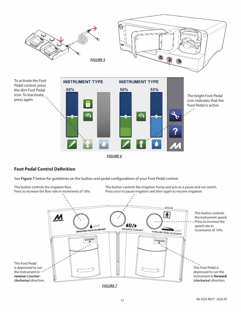
Plug the Foot Pedal Cable into the Foot Control Pedal and then plug the other end into the Console port marked with the Foot Pedal symbol as shown in Figure 5.
To activate the Foot Pedal, press the Foot Pedal Control icon. Press again to inactivate the Foot Pedal as shown in Figure 6. The Foot Pedal icon does not respond if pressed while the instrument is running.
NOTE: The Foot Pedal icon is only visible for instruments that are able to be run by the Foot Pedal. If the icon is not present Foot Pedal control is not available for that instrument. NOTE: Foot Pedal can only control one instrument at a time. If the Foot Pedal is active for Instrument 1 and you wish to change to Instrument 2, make sure that neither connected instrument is running, then press the Foot Pedal icon on the instrument of your choice to activate the Foot Pedal for that instrument.
12 IM-5025 REV F 2020-05
á
á
FIGURE 5
To activate the Foot Pedal control, press the dim Foot Pedal icon. To inactivate, press again.
FIGURE 6
The bright Foot Pedal icon indicates that the Foot Pedal is active.
á
This button controls the irrigation flow. Press to increase the flow rate in increments of 10%.
This Foot Pedal is depressed to run the instrument in reverse (counter-clockwise) direction.
This Foot Pedal is depressed to run the instrument in forward (clockwise) direction.
This button controls the instrument speed. Press to increase the speed rate in increments of 10%.
This button controls the Irrigation Pump and acts as a pause and run switch. Press once to pause irrigation and then again to resume irrigation.
FIGURE 7
Foot Pedal Control Definition
See Figure 7 below for guidelines on the button and pedal configurations of your Foot Pedal control.
13IM-5025 REV F 2020-05
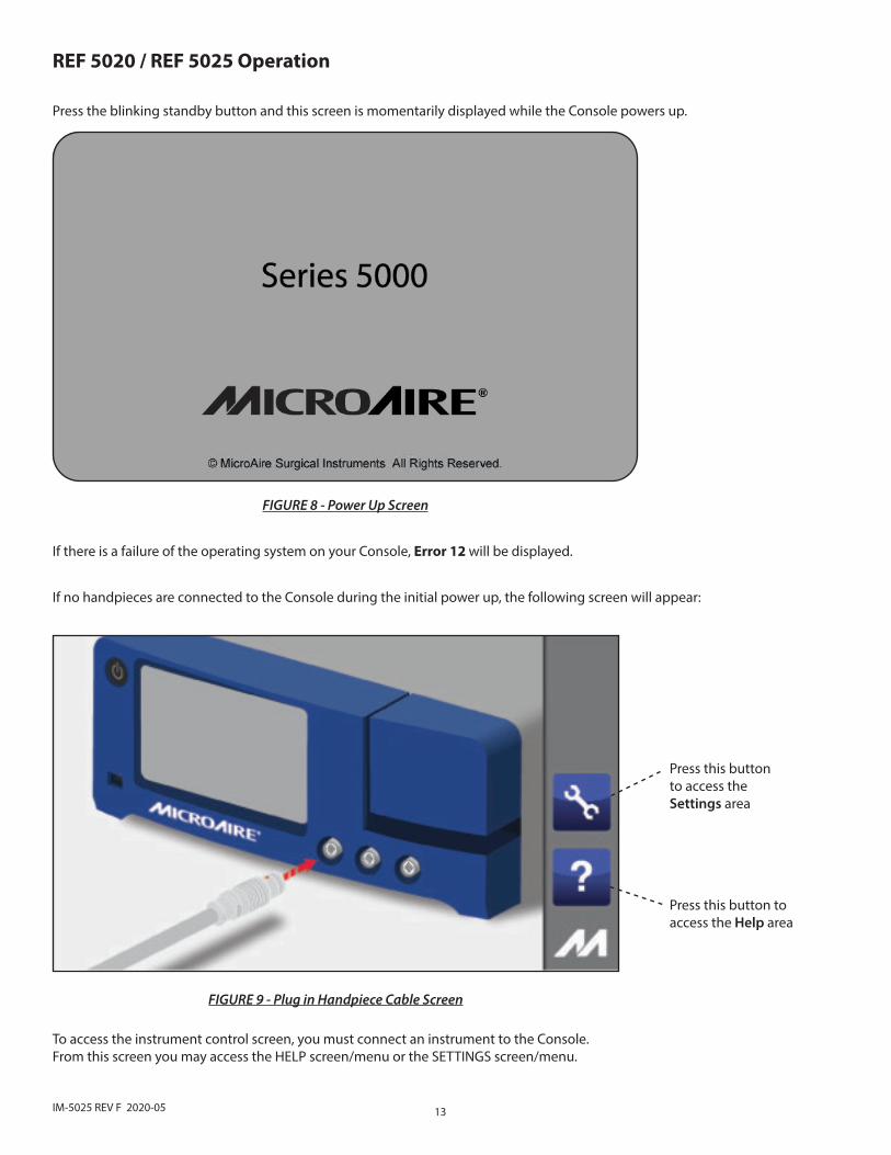
REF 5020 / REF 5025 Operation
Press the blinking standby button and this screen is momentarily displayed while the Console powers up.
FIGURE 8 - Power Up Screen
If there is a failure of the operating system on your Console, Error 12 will be displayed.
Press this button to access the Help area
Press this buttonto access theSettings area
If no handpieces are connected to the Console during the initial power up, the following screen will appear:
FIGURE 9 - Plug in Handpiece Cable Screen
To access the instrument control screen, you must connect an instrument to the Console.From this screen you may access the HELP screen/menu or the SETTINGS screen/menu.
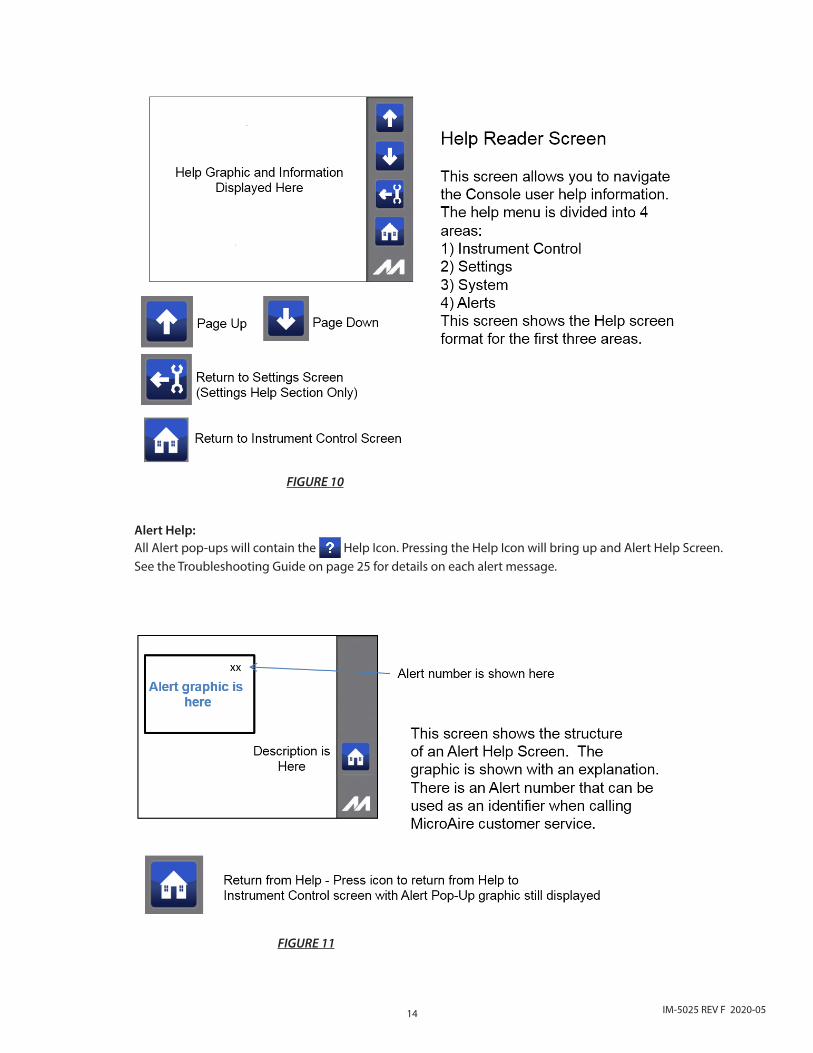
14 IM-5025 REV F 2020-05
Alert Help:All Alert pop-ups will contain the Help Icon. Pressing the Help Icon will bring up and Alert Help Screen. See the Troubleshooting Guide on page 25 for details on each alert message.
FIGURE 10
FIGURE 11
15IM-5025 REV F 2020-05
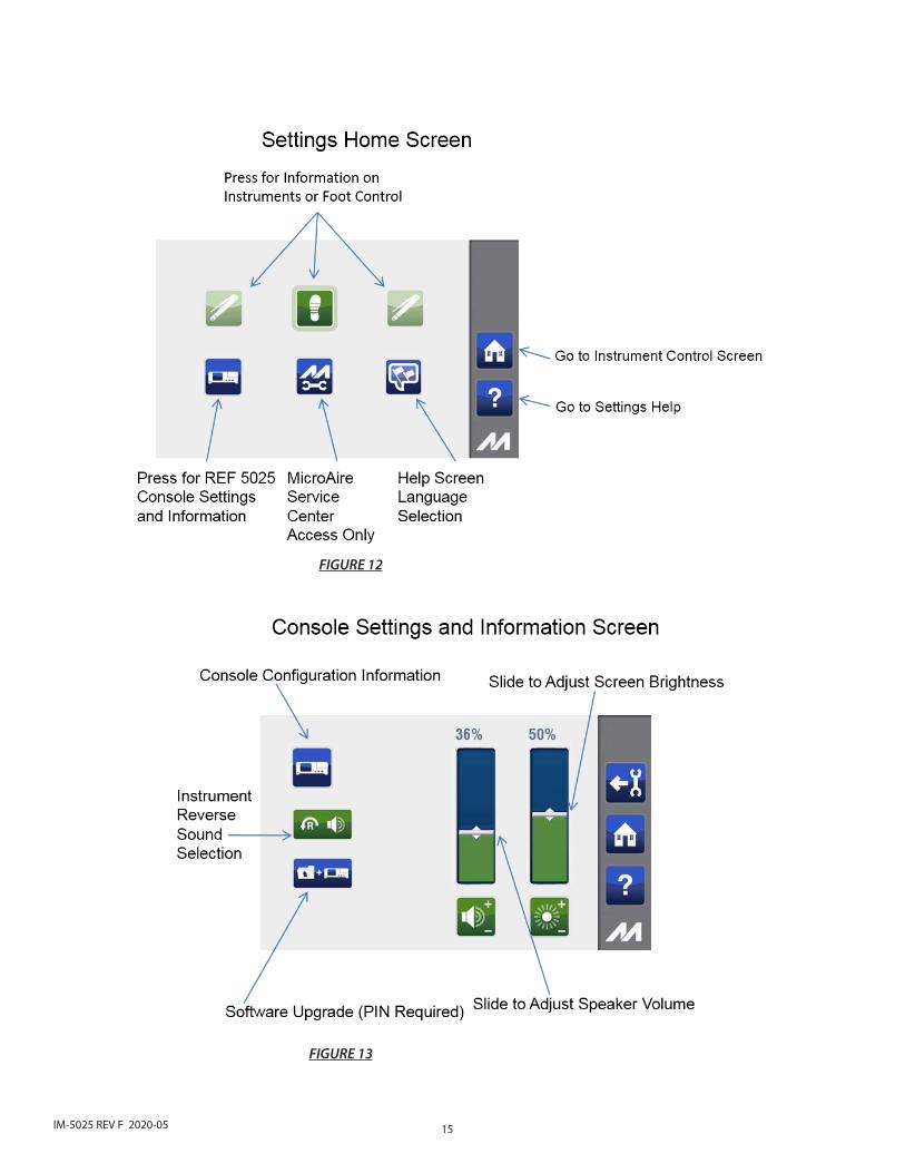
FIGURE 12
FIGURE 13
16 IM-5025 REV F 2020-05
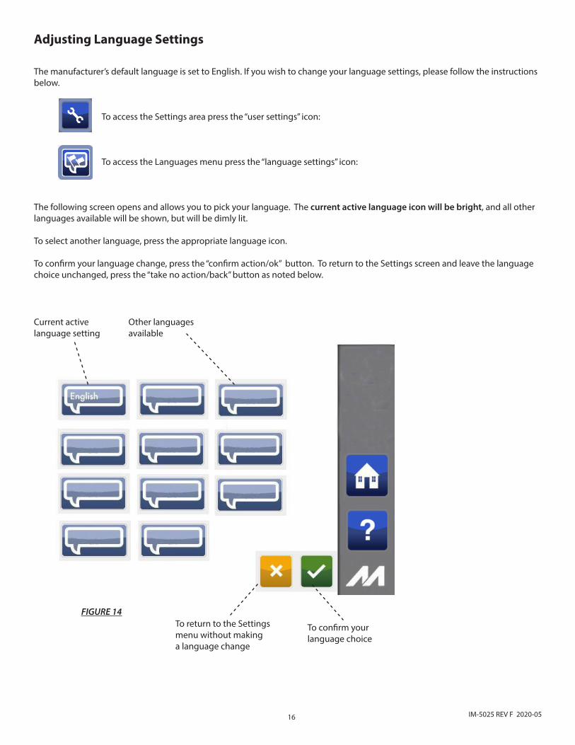
Adjusting Language Settings
The manufacturer’s default language is set to English. If you wish to change your language settings, please follow the instructions below.
To access the Settings area press the “user settings” icon:
To access the Languages menu press the “language settings” icon:
The following screen opens and allows you to pick your language. The current active language icon will be bright, and all other languages available will be shown, but will be dimly lit.
To select another language, press the appropriate language icon.
To confirm your language change, press the “confirm action/ok” button. To return to the Settings screen and leave the language choice unchanged, press the “take no action/back” button as noted below.
Current active language setting
FIGURE 14
Other languages available
To confirm your language choice
To return to the Settings menu without making a language change
17IM-5025 REV F 2020-05
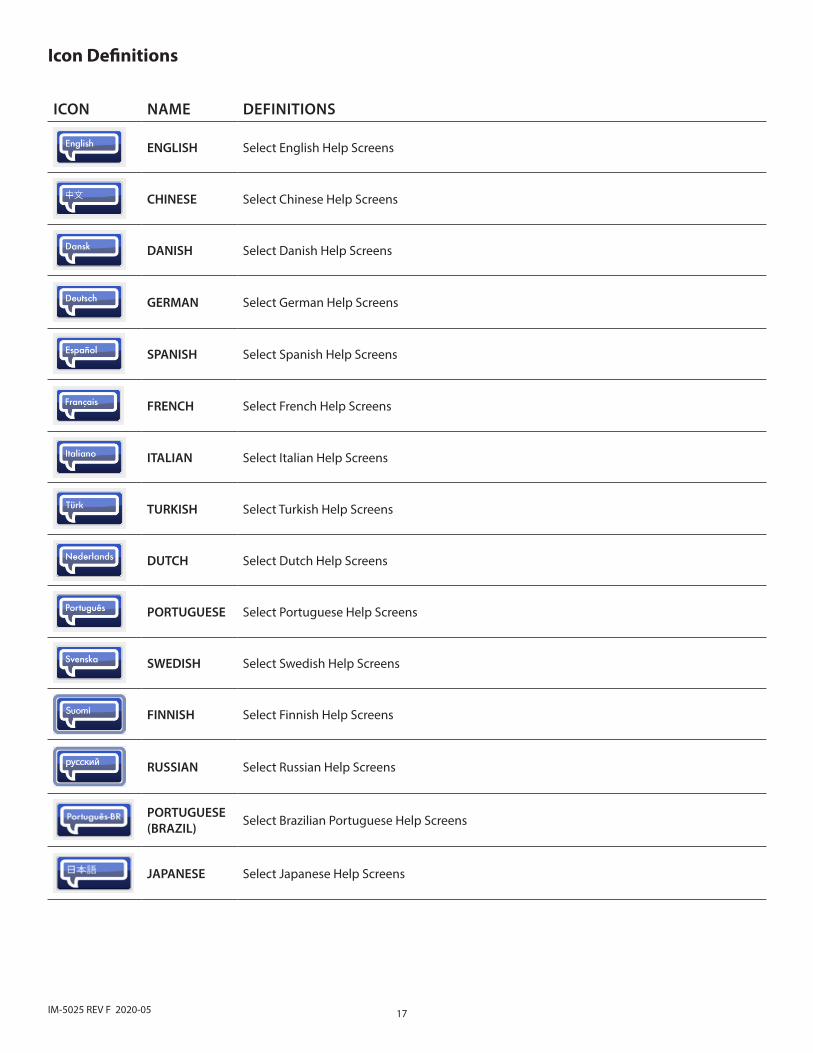
ICON NAME DEFINITIONS
ENGLISH Select English Help Screens
CHINESE Select Chinese Help Screens
DANISH Select Danish Help Screens
GERMAN Select German Help Screens
SPANISH Select Spanish Help Screens
FRENCH Select French Help Screens
ITALIAN Select Italian Help Screens
TURKISH Select Turkish Help Screens
DUTCH Select Dutch Help Screens
PORTUGUESE Select Portuguese Help Screens
SWEDISH Select Swedish Help Screens
FINNISH Select Finnish Help Screens
RUSSIAN Select Russian Help Screens
PORTUGUESE (BRAZIL) Select Brazilian Portuguese Help Screens
JAPANESE Select Japanese Help Screens
Icon Definitions
18 IM-5025 REV F 2020-05
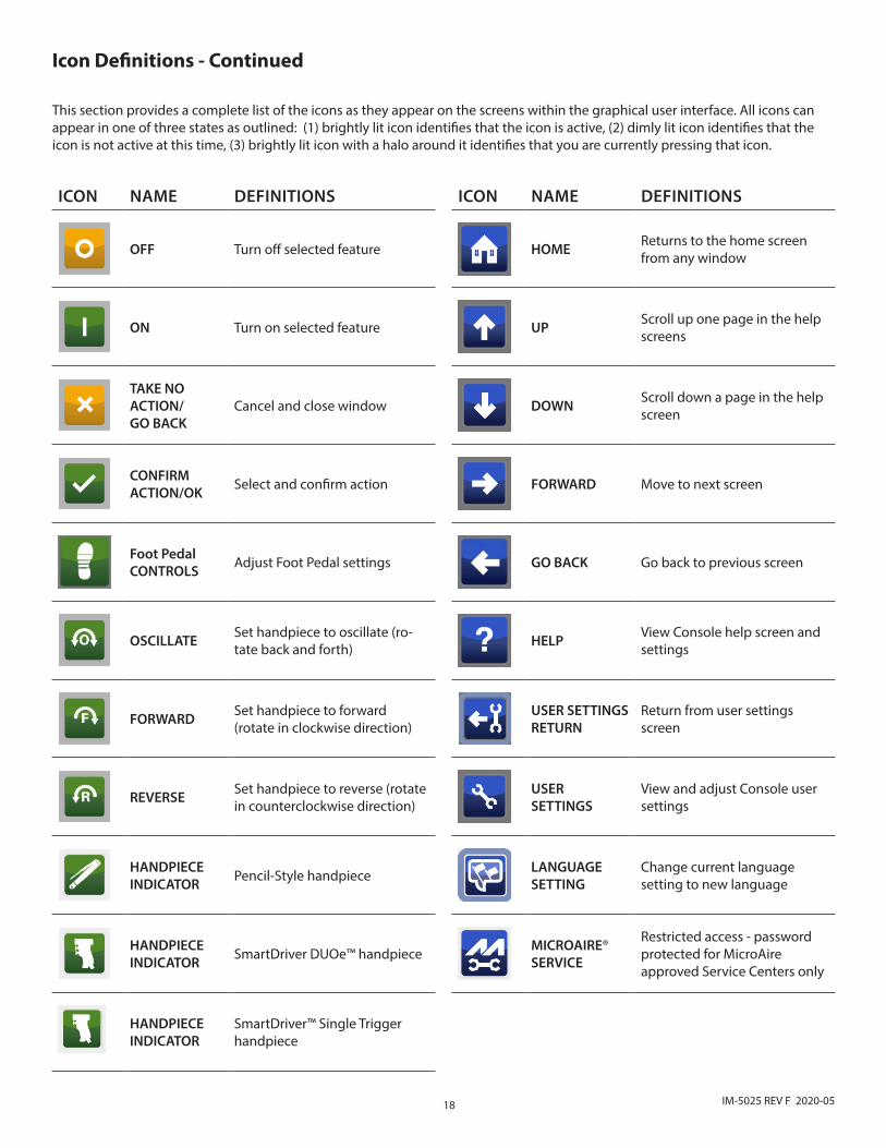
Icon Definitions - Continued
This section provides a complete list of the icons as they appear on the screens within the graphical user interface. All icons can appear in one of three states as outlined: (1) brightly lit icon identifies that the icon is active, (2) dimly lit icon identifies that the icon is not active at this time, (3) brightly lit icon with a halo around it identifies that you are currently pressing that icon.
ICON NAME DEFINITIONS ICON NAME DEFINITIONS
OFF Turn off selected feature HOME Returns to the home screen from any window
ON Turn on selected feature UP Scroll up one page in the help screens
TAKE NO ACTION/ GO BACK
Cancel and close window DOWN Scroll down a page in the help screen
CONFIRM ACTION/OK Select and confirm action FORWARD Move to next screen
Foot Pedal CONTROLS Adjust Foot Pedal settings GO BACK Go back to previous screen
OSCILLATE Set handpiece to oscillate (ro-tate back and forth) HELP View Console help screen and
settings
FORWARD Set handpiece to forward (rotate in clockwise direction)
USER SETTINGSRETURN
Return from user settings screen
REVERSE Set handpiece to reverse (rotate in counterclockwise direction)
USERSETTINGS
View and adjust Console user settings
HANDPIECEINDICATOR Pencil-Style handpiece LANGUAGE
SETTINGChange current language setting to new language
HANDPIECEINDICATOR SmartDriver DUOe™ handpiece MICROAIRE®
SERVICE
Restricted access - password protected for MicroAire approved Service Centers only
HANDPIECEINDICATOR
SmartDriver™ Single Trigger handpiece

19IM-5025 REV F 2020-05
ICON NAME DEFINITIONS ICON NAME DEFINITIONS
IRRIGATORSETTINGS Adjust irrigator settings SOFTWARE
UPGRADESoftware Upgrade (MicroAire Authorized Service Only)
Console SETTINGS
View and adjust Console display settings DISCONNECT Disconnect all instruments &
Foot Pedal from Console
ADJUSTBRIGHTNESS
View and adjust Console brightness Foot Pedal Icon for Foot Pedal information
ADJUSTSOUNDS View and adjust Console sounds INSTRUMENT A Icon for Instrument A
information
MUTE Mute Reverse Audio INSTRUMENT B Icon for Instrument B information
REVERSE DIRECTION AUDIO
Reverse Audio set up icon IRRIGATOR Icon for irrigator pump information
ONE TIME Play reverse audio one time only
CONTINUOUS PLAY
Continuous play of reverse audio
HANDPIECE INDICATOR Solo™ handpiece
LOCK INDICATOR
Indicates that handpiece is locked and in safe position
HANDPIECE INDICATOR PAL® handpiece
Icon Definitions - Continued
20 IM-5025 REV F 2020-05
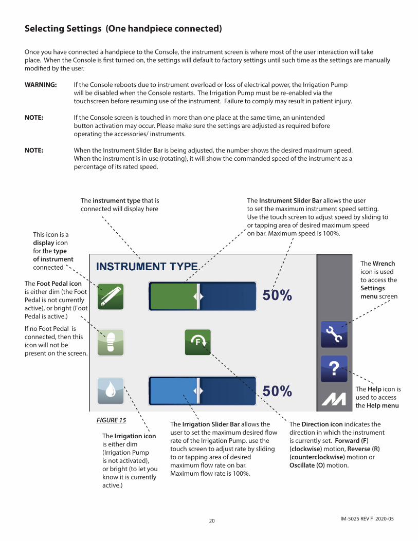
Selecting Settings (One handpiece connected)
Once you have connected a handpiece to the Console, the instrument screen is where most of the user interaction will take place. When the Console is first turned on, the settings will default to factory settings until such time as the settings are manually modified by the user.
WARNING: If the Console reboots due to instrument overload or loss of electrical power, the Irrigation Pump will be disabled when the Console restarts. The Irrigation Pump must be re-enabled via the touchscreen before resuming use of the instrument. Failure to comply may result in patient injury.
NOTE: If the Console screen is touched in more than one place at the same time, an unintended button activation may occur. Please make sure the settings are adjusted as required before operating the accessories/ instruments.
NOTE: When the Instrument Slider Bar is being adjusted, the number shows the desired maximum speed. When the instrument is in use (rotating), it will show the commanded speed of the instrument as a percentage of its rated speed.
The instrument type that is connected will display here
The Instrument Slider Bar allows the user to set the maximum instrument speed setting. Use the touch screen to adjust speed by sliding to or tapping area of desired maximum speed on bar. Maximum speed is 100%.
FIGURE 15
This icon is a display icon for the type of instrument connected The Wrench
icon is used to access the Settings menu screen
The Help icon is used to access the Help menu
The Foot Pedal icon is either dim (the Foot Pedal is not currently active), or bright (Foot Pedal is active.)
If no Foot Pedal is connected, then this icon will not be present on the screen.
The Direction icon indicates the direction in which the instrument is currently set. Forward (F) (clockwise) motion, Reverse (R) (counterclockwise) motion or Oscillate (O) motion.
The Irrigation Slider Bar allows the user to set the maximum desired flow rate of the Irrigation Pump. use the touch screen to adjust rate by sliding to or tapping area of desired maximum flow rate on bar. Maximum flow rate is 100%.
The Irrigation icon is either dim (Irrigation Pump is not activated), or bright (to let you know it is currently active.)
21IM-5025 REV F 2020-05
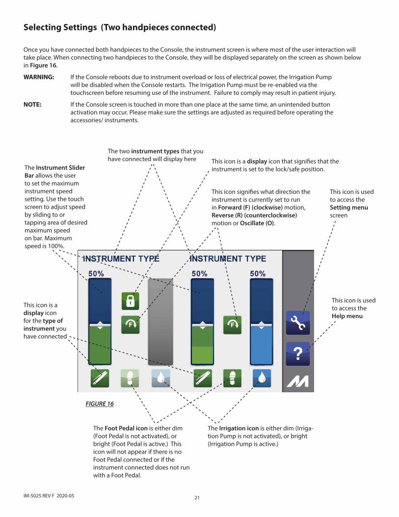
The Instrument Slider Bar allows the user to set the maximum instrument speed setting. Use the touch screen to adjust speed by sliding to or tapping area of desired maximum speed on bar. Maximum speed is 100%.
The Foot Pedal icon is either dim (Foot Pedal is not activated), or bright (Foot Pedal is active.) This icon will not appear if there is no Foot Pedal connected or if the instrument connected does not run with a Foot Pedal.
This icon is used to access the Setting menu screen
This icon is used to access the Help menu
The Irrigation icon is either dim (Irriga-tion Pump is not activated), or bright (Irrigation Pump is active.)
This icon is a display icon for the type of instrument you have connected
This icon signifies what direction the instrument is currently set to run in Forward (F) (clockwise) motion, Reverse (R) (counterclockwise) motion or Oscillate (O).
Selecting Settings (Two handpieces connected)
Once you have connected both handpieces to the Console, the instrument screen is where most of the user interaction will take place. When connecting two handpieces to the Console, they will be displayed separately on the screen as shown below in Figure 16.
WARNING: If the Console reboots due to instrument overload or loss of electrical power, the Irrigation Pump will be disabled when the Console restarts. The Irrigation Pump must be re-enabled via the touchscreen before resuming use of the instrument. Failure to comply may result in patient injury.
NOTE: If the Console screen is touched in more than one place at the same time, an unintended button activation may occur. Please make sure the settings are adjusted as required before operating the accessories/ instruments.
The two instrument types that you have connected will display here
FIGURE 16
This icon is a display icon that signifies that the instrument is set to the lock/safe position.
22 IM-5025 REV F 2020-05
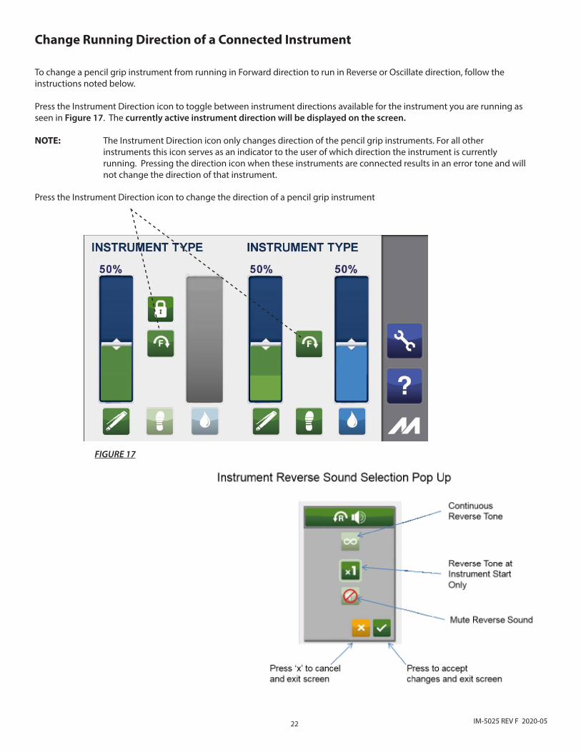
Press the Instrument Direction icon to change the direction of a pencil grip instrument
Change Running Direction of a Connected Instrument
To change a pencil grip instrument from running in Forward direction to run in Reverse or Oscillate direction, follow the instructions noted below.
Press the Instrument Direction icon to toggle between instrument directions available for the instrument you are running as seen in Figure 17. The currently active instrument direction will be displayed on the screen.
NOTE: The Instrument Direction icon only changes direction of the pencil grip instruments. For all other instruments this icon serves as an indicator to the user of which direction the instrument is currently running. Pressing the direction icon when these instruments are connected results in an error tone and will not change the direction of that instrument.
FIGURE 17
23IM-5025 REV F 2020-05
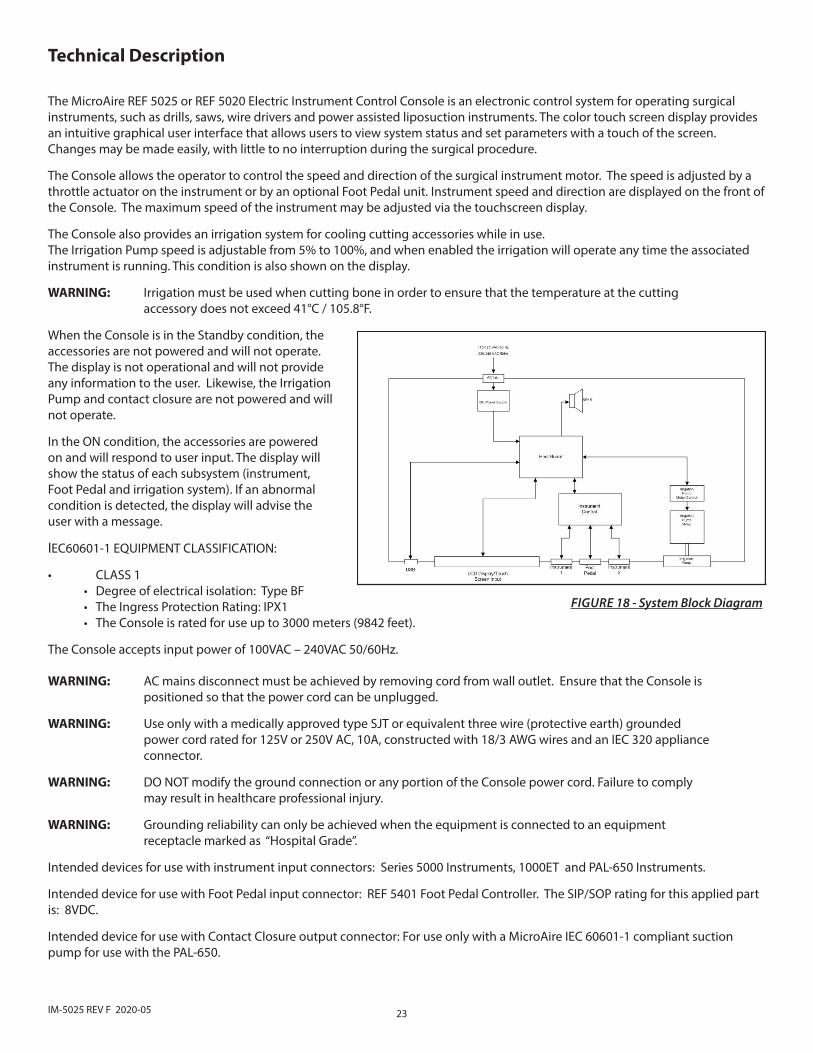
FIGURE 18 - System Block Diagram
The MicroAire REF 5025 or REF 5020 Electric Instrument Control Console is an electronic control system for operating surgical instruments, such as drills, saws, wire drivers and power assisted liposuction instruments. The color touch screen display provides an intuitive graphical user interface that allows users to view system status and set parameters with a touch of the screen. Changes may be made easily, with little to no interruption during the surgical procedure.
The Console allows the operator to control the speed and direction of the surgical instrument motor. The speed is adjusted by a throttle actuator on the instrument or by an optional Foot Pedal unit. Instrument speed and direction are displayed on the front of the Console. The maximum speed of the instrument may be adjusted via the touchscreen display.
The Console also provides an irrigation system for cooling cutting accessories while in use. The Irrigation Pump speed is adjustable from 5% to 100%, and when enabled the irrigation will operate any time the associated instrument is running. This condition is also shown on the display.
WARNING: Irrigation must be used when cutting bone in order to ensure that the temperature at the cutting accessory does not exceed 41°C / 105.8°F.
When the Console is in the Standby condition, the accessories are not powered and will not operate. The display is not operational and will not provide any information to the user. Likewise, the Irrigation Pump and contact closure are not powered and will not operate.
In the ON condition, the accessories are powered on and will respond to user input. The display will show the status of each subsystem (instrument, Foot Pedal and irrigation system). If an abnormal condition is detected, the display will advise the user with a message.
Technical Description
IEC60601-1 EQUIPMENT CLASSIFICATION:
• CLASS 1• Degree of electrical isolation: Type BF• The Ingress Protection Rating: IPX1• The Console is rated for use up to 3000 meters (9842 feet).
The Console accepts input power of 100VAC – 240VAC 50/60Hz.
WARNING: AC mains disconnect must be achieved by removing cord from wall outlet. Ensure that the Console is positioned so that the power cord can be unplugged.
WARNING: Use only with a medically approved type SJT or equivalent three wire (protective earth) grounded power cord rated for 125V or 250V AC, 10A, constructed with 18/3 AWG wires and an IEC 320 appliance connector.
WARNING: DO NOT modify the ground connection or any portion of the Console power cord. Failure to comply may result in healthcare professional injury.
WARNING: Grounding reliability can only be achieved when the equipment is connected to an equipment receptacle marked as “Hospital Grade”.
Intended devices for use with instrument input connectors: Series 5000 Instruments, 1000ET and PAL-650 Instruments.
Intended device for use with Foot Pedal input connector: REF 5401 Foot Pedal Controller. The SIP/SOP rating for this applied part is: 8VDC.
Intended device for use with Contact Closure output connector: For use only with a MicroAire IEC 60601-1 compliant suction pump for use with the PAL-650.
24 IM-5025 REV F 2020-05
WARNING: Anyone who connects additional equipment to the contact closure connector configures a medical system, and is therefore responsible that the system complies with the requirements of clause 16 of ANSI/AAMI/IEC ES60601-1:2005 + Am1 (2012).
Intended devices for use with a USB Flash Drive. The SIP/SOP rating for this connector is: 5VDC.
WARNING: The USB port is to be used only for diagnostics and/or software upgrade by MicroAire approved technicians only. The USB port must not be connected to any cable or device while in operation.
Cleaning and Sterilization Guidelines
MicroAire’s powered surgical instruments (ie. handpieces, handpiece cable, etc.) are normally sterilized by steam, using dynamic air removal steam sterilizer. For specific sterilization instructions for handpieces, see their respective Instructions for Use.
CAUTION: DO NOT sterilize the 5025/5020 Console, power cord or 5401 Foot Pedal. - They may be wiped down with a germicidal cleaner. Take precautions to avoid allowing any moisture inside of any Console opening and power cord.
CAUTION: DO NOT use aerosol sprays of any kind directly on the screen display of the Console. Clean by wiping with a soft, damp cloth and drying with a soft dry cloth.
Environmental Parameters
Shipping and Storage ConditionsThe REF 5020, REF 5025, REF 5401 and REF 5025-5401 can be shipped by any standard commercial method without special handling conditions.
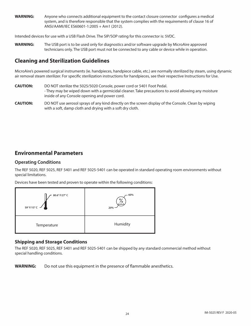
Operating ConditionsThe REF 5020, REF 5025, REF 5401 and REF 5025-5401 can be operated in standard operating room environments without special limitations.
Devices have been tested and proven to operate within the following conditions:
WARNING: Do not use this equipment in the presence of flammable anesthetics.
Temperature Humidity
59° F/15° C
80.6° F/27° C
20%
60%

25IM-5025 REV F 2020-05
Troubleshooting GuidelinesProblem:Sporadic or intermittent electrical interference is experienced with the Console.
Solution:Turn off all electrical equipment not in use in the operating room. Relocate electrical equipment and increase the distance of this equipment from the Console. Plug the Console into a different outlet than other operating room equipment.
ALERT BANNERS
Instrument Alert - Accompanies graphics or text showing the condition of either the instrument or the Foot Pedal.
Irrigation Pump Alert - Accompanies graphics or text showing the condition of the Irrigation Pump or pump head.
System Alert - Accompanies graphics or text showing the internal condition of the Console.
ALERTS ICON DEFINITIONS This section provides a complete list of the icons as they appear on the screens within the graphical user interface.
ICON NAME DEFINITIONS CAUSES OF PROBLEM
Error 12Internal Error
Internal Console Malfunction. Contact MicroAire.
There is a problem internal to the REF 5020 / REF 5025 Console. Return the Console for service.
Error 13 Internal Temperature Stop
Temperature of motor drive circuit has exceeded safe levels. Instrument operation will be suspended until the Console circuits cool down.
Continued operation of instrument after receiving Error 14 Alert
Error 14 InternalTemperature Warning
Temperature of motor drive circuit has exceeded normal levels. Instrument shutdown pending.
Operation of the Console at excessive ambient temperatures or duty cycles.
Error 16Bad Hall Sensor
Invalid Motor Sensor Signal. Instrument Motor Can Not Operate. Contact MicroAire.
The Console is detecting invalid sensor signals. The cause is most often in the instrument or instrument cable, but can also be a sign of a damaged Console. Return all involved instruments, cables and Consoles for service.
Error 18 StallInstrument has stalled. Ensure Cutting accessory is not bound up and retry. If problem persists, contact MicroAire.
This can be a sign of overly aggressive technique that binds the cutting accessory. It can also be caused by a mechanically seized instrument, or an open motor connection in the instrument cable.
Error 21Irrigator Alert
Indicates a malfunction with the irrigator pump. Check that Irrigation tubing is installed correctly and retry. If problem persists, contact MicroAire.
This occurs when the Irrigation Pump is run with no tubing installed, or if the pump rotor becomes jammed up. Check installation of irrigation tubing and try again.
Error 22Unrecognized Instrument
Console does not recognize instrument. Check that connector pins are clean and undamaged and retry. If problem persists, contact MicroAire.
This can occur due to problems in either the instrument cable or the instrument itself that result in the instrument type not being recognized by the Console.

26 IM-5025 REV F 2020-05
Maintenance Information
Prior to every use, inspect the Console for damage and signs of wear. DO NOT USE the Console if there is any visible sign of damage/wear, or if you suspect the reliability of the Console is compromised. Inspect and test periodically in accordance with your facility’s bioengineering policy. In addition, prior to every use, each instrument cable, handpiece and Foot Pedal, if applicable, must be inspected for damage and signs of wear. Inspect the connector(s) for any damaged or bent pins; also inspect the entire length of the cable for any wear. DO NOT USE if there is any visible sign of damage/wear, or if you suspect the reliability of any of the accessories is compromised. All accessories should be subjected to department maintenance schedule. Inspection and test results should be documented within the bioengineering department.
WARNING: Modification of this equipment is not allowed.
WARNING: Electric Shock. Do not remove cover. Refer servicing to authorized MicroAire personnel only.
This Console is not field repairable. If you experience damage, operating difficulties, or anything negatively effecting affecting the performance of the Console, contact MicroAire® Customer Service. MicroAire may be able to assist you in solving the problem quickly without returning the item to our service center. DO NOT attempt to disassemble or attempt to service the equipment on your own. This equipment can only be serviced at a MicroAire® approved service center by factory-trained technicians. Please return the product only to MicroAire® Surgical Instruments. For more information or instructions on how to return your Console for service, please contact:
MicroAire Surgical Instruments Customer Service Center at 1-800-722-0822 or 434-975-8000. By mail at: 3590 Grand Forks Blvd., Charlottesville, Virginia, 22911.
Proper Shipping, Storage and HandlingTo ensure the safety of your equipment when shipping, storing or handling, place in the original packaging container with the original packing materials.
Essential Performance StatementThe 5020/5025 Electric Instrument Control Console has no Essential Performance as defined by ANSI/AAMI/IEC ES60601-1 when used with the PAL-650 instruments.
The 5020/5025 Electric Instrument Control Console has no Essential Performance as defined by ANSI/AAMI/IEC ES60601-1 when used with the Series 5000 family of instruments.
Electromagnetic Compatibility (EMC)WARNING: Take special precautions with electromagnetic compatibility (EMC) when using the MicroAire Electric Instrument Console. Ensure that the Console is installed and placed into service according to the EMC information contained in the Instructions for Use. WARNING: The 5020 / 5025 Electric Instrument Control Console and associated instruments have been tested for use in the vicinity of High Frequency Electrosurgical/ Electrocoagulation equipment. Use of such equipment in close proximity to the MicroAire instruments or instrument cables may cause unintended interruptions or unintended motion of durations up to 1 second. Place MicroAire Instruments on a safe surface when not in use. Do not place MicroAire Instruments on the patient when not in use. Avoid entwining HF surgical cables with MicroAire Instrument Cables. WARNING: Portable RF communications equipment should be used no closer than 30 cm (12 inches) away from any part of the 5020 /5025 Console, its associated cables or the handpieces it is controlling. Otherwise degradation of the performance of the PAL-650 or Series 5000 instruments could result. WARNING: Use of the 5020 /5025 Console adjacent to or stacked with other equipment should be avoided because it could result in improper operation. If such use is necessary, the 5020 / 5205 and the adjacent equipment should be observed to verify that they are operating normally.

27IM-5025 REV F 2020-05
WARNING: The following items should be periodically inspected for signs of damage and repaired or replaced as needed to ensure continued safety with regard to electromagnetic disturbances over the life of the system: • 5020 / 5025 Electric Instrument Control Console: - Proper Fit of the top cover to the chassis. - Damage to the LCD Display - Test that the Protective Earth Connection meets ES60601-1 requirements. • Inspect the 5006-XXXX instrument cables for signs of physical damage to the cable. WARNING: The 5020 & PAL-650 Liposuction handpiece and the 5025 & Series 5000 Instrument System are suitable for use in hospitals and surgery centers. These systems should not be used near Magnetic Resonance Imaging equipment. NOTE: Connection of the Potential Equalization Connector is not required for compliance with IEC 60601-1 or IEC 60601-1-2.
NOTE: The emissions characteristics of this product make it suitable for use in industrial areas and hospitals (CISPR 11 Class A). If it is used in a residential environment (for which CISPR 11 Class B is normally required) this equipment might not offer adequate protection to radio frequency communication services. The user might be required to take mitigation measures, such as relocating or re-orienting the equipment.
Unless otherwise Noted, the following EMC Compliance information applies to 5020 or 5025 Electric Consoles when used with the PAL-650 or the 5000 Series Orthopedic Instruments.
EMC Test & Standard Test Levels / Limits Compliance
Mains terminal disturbance voltage (conducted emissions): CISPR 11 CISPR 11 Class A Complies with Class A Limits
Electromagnetic radiation disturbance (radiated emissions): CISPR 11 CISPR 11 Class A Complies with Class A Limits
Harmonic distortion: IEC 61000-3-2 IEC 61000-3-2 Class A Complies with Class A Limits
Voltage fluctuations and flicker: IEC 61000-3-3 IEC 61000-3-3 Class A Complies with Class A Limits
Electrostatic discharge immunity: IEC 61000-4-2
Discharge Level (kV)Contact – Direct: + /- 8Contact – Indirect: +/- 8Air +/- 2, 4, 8, 15
Complies Per*Complies Per*Complies Per*
Radiated RF electromagnetic field im-munity: IEC 61000-4-3
3V/m 80MHz to 2700 MHz 80% AM at 1 KHz
Complies Per*
Immunity to proximity fields from RF wireless communications equipment: IEC 61000-4-3
IEC 60601-1-2 Table 9 Complies Per*
Immunity to High Frequency Surgical Equipment: IEC 60601-2-2
Tested for immunity to modern (non-spark gap) HF Surgical Equipment per the guidelines of IEC60601-2-2:2017 Annex BB.
Cut Mode at 150 Watts:
Coagulate Mode at 70 Watts:
The HF Surgical generator was in operation as part of the EM environment for all other immunity tests.
Complies Per*
Complies Per*
See Other Immunity Tests

28 IM-5025 REV F 2020-05
EMC Test & Standard Test Levels / Limits Compliance
Electrical fast transient/burst immunity – IEC 61000-4-4 AC mains: I/O SIP/SOP Ports:
+/- 2KV 100KHz Repetition Frequency +/- 1KV 100KHz Repetition Frequency
Complies Per*
Complies Per*
Surge Immunity: IEC 61000-45 Input Power Ports (Line to Line) (Line to Earth)
0.5kV and 1.0kV Combination Wave (2µs x 50µs Voltage, 8µs x 20µs Current)
0.5kV, 1.0kV and 2.0kV Combination Wave (2µs x 50µs Voltage, 8µs x 20µs Current)
Complies Per*
Complies Per*
Immunity to conducted disturbances induced by RF fields (conducted RF disturbance immunity) – a.c. mains: IEC 61000-4-6
Frequency range: 150kHz to 80MHz
Level: 3 V outside the ISM band, 6 V in the ISM bands between 0.15 MHz and 80 MHz
Complies Per*
Input AC Power CordFrequency step: 1%Modulation: 80% Am at 1kHzDwell Time: Minimum 1 s
N/A
Power Frequency Magnetic Field Immunity: IEC 61000-4-8
Frequency: 50 Hz or 60 HzTest Level: 30 A/m Complies Per*
Field Immunity: IEC 61000-48 Test Level: 30 A/m TBD
Voltage Dips: IEC 61000-4-11
Dip to 0V for 1 Cycle with 0 Degree Sync Angle.
Dip to 0V for 0.5 Cycles with Sync Angles of 0,45,90,135,180,225,270,315 degrees
Dip to 70% of 240V for 25 Cycles at 50Hz
Dip to 70% of 100V for 30 Cycles at 60Hz
Complies Per*
Complies Per*
Complies Per*
Complies Per*
Voltage Interruptions Immunity: IEC 61000-4-11
Dip to 0V for 5ms. (250 Cycles at (50Hz) or 300 Cycles at 60 Hz) Complies Per*
*The PAL-650 and 5000 Series Orthopedic Instruments have no Essential Performance. Compliance with Immunity Testing is defined as a) the system will remain functional after the test, and b) instruments in a standby mode will not run for more than 1 second as a result of the test.
Guidance and manufacturer’s declaration – power output, vibration exposure, noise emission value and mass weight information
Power OutputkW - KiloWatts
Vibration Exposure ahv(m/s2) Uncertainty K (m/s2)
Noise Emission Value LPA (dB(A)) LC,peak (dB(C)) LWA (dB(A))
Mass Weight (kg)
0.30 - - - - - 8.2
29IM-5025 REV F 2020-05
Warranty, Service, Repair and DisposalWarranty
MicroAire® Surgical Instruments warrants the 5025 and 5020 Console to be free from defects in material and workmanship in their manufacture for a period of 1 (one) year from the original purchase date by the end customer. This warranty is limited to the repair or replacement of the product without charge.
This warranty is null and void in the event of abuse, misuse, or use in other than a normal surgical environment, or in the event of disassembly, alteration, or repair of the product not authorized by MicroAire®, or in the event that the product has not been used in a reasonable manner and in compliance with the written instructions furnished by MicroAire®. Using any accessory that is not a MicroAire® product will void your warranty.
All other expressed or implied warranties and all other warranties of fitness or merchantability are excluded here from, and MicroAire® shall have no liability of any kind for incidental or consequential damages.
NOTE: Repairs or alterations to MicroAire® products made by anyone other than MicroAire® or an Authorized MicroAire® Repair Facility will void that product’s warranty, and the customer will be responsible for any costs related to returning the product to working condition.
Extended WarrantyExtended warranties may be purchased while the equipment is covered by the original warranty. If the equipment is out of warranty, it must first be restored, if necessary, to full serviceable condition before being eligible for a service agreement.
Periodic inspection and service is essential to keep precision MicroAire® products running properly.
Service and RepairResponsive service comes with every MicroAire® product. If a problem with your equipment should arise, contact our Customer Service Department at:
Telephone: Fax: E-Mail:USA 800-722-0822 800-648-4309 [email protected] USA 434-975-8000 434-975-4134 [email protected]
NOTE: MicroAire® mailing address information is located on the back cover of this Instructions for Use document.
MicroAire® may be able to solve the problem quickly without requiring return of the item for service. DO NOT disassemble or attempt to service the equipment. It can only be serviced by MicroAire® or an Authorized MicroAire® Repair Facility. Unauthorized service will void the warranty.
To return an item for service, follow these guidelines listed below:
Contact MicroAire® Customer Service for a Return Material Authorization (RMA) number.
NOTE: DO NOT return equipment without an RMA number. Doing so could cause delays in service, and/or problems tracking your equipment.
Clean and disinfect all equipment prior to sending in for repair.
Along with the items sent for repair, enclose a detailed description of the problem encountered, the type of use, the place of use, a contact name and a telephone number.
If the instrument is out of warranty, enclose a purchase order number with the instrument to be used in the event that you approve your quote to proceed with the service. If the instrument is under warranty, please include the purchase date.
In the United States, ship the merchandise by Express Mail, Federal Express or UPS Blue Label to prevent shipping delays. From outside the United States, return goods by Federal Express, UPS or Air Freight.
Return the merchandise prepaid.
If an estimate of repair costs is needed before repairs are made, include the name and telephone number of the person to contact.
30 IM-5025 REV F 2020-05
Periodic InspectionBecause of the stressful nature of surgical use, decontamination, and sterilization, we recommend that all products be returned for routine inspection and service at least once per year.
MICROAIRE WILL NOT BE LIABLE FOR ANY INDIRECT, SPECIAL, PUNITIVE OR CONSEQUENTIAL DAMAGES ARISING OUT OF ANY USE OF THIS PRODUCT.
By using this Console and its software, you acknowledge and agree that you have read, understood and agree to be bound by these terms and conditions.
Disposal - (2002/96/EC Directive on Waste Electrical and Electronic Equipment)In accordance with the 2002/96/EC Directive on Waste Electrical and Electronic Equipment (the WEEE Directive) and the current national provisions, the organization of the transfer of these wastes for devices sold by MANUFACTURER shall be undertaken by DISTRIBUTOR. For this reason, DISTRIBUTOR shall organize a system for the collection, storage and arrange transfer of any and all WEEE components to a Manufacturer’s approved WEEE collection facility in Europe. DISTRIBUTOR shall provide on request to MANUFACTURER, the proof of compliance with the European and national provisions regarding the WEEE Directive. Please refer to www.microaire.com/weee-directive for WEEE Compliance Instructions.
NOTES

31IM-5025 REV F 2020-05

32 IM-5025 REV F 2020-05

33IM-5025 REV F 2020-05

34 IM-5025 REV F 2020-05
©2020 MicroAire Surgical Instruments LLCPrinted in the USAIM-5025 Rev F 2020-05
MicroAire Surgical Instruments LLC 3590 Grand Forks Blvd Charlottesville, VA 22911 USA Telephone (800) 722-0822 (434) 975-8000
Fax (800) 648-4309 (434) 975-4131 www.microaire.com
MediMark Europe11, rue Emile Zola - BP 2332F-38033 Grenoble Cedex 2 France
E2797