Embed Size (px)
Citation preview
Instructions for use
Title Study on a Magnetic Dynamic Vibration Absorber with Adjustable Natural Frequency
Author(s) Igarasi, Satoru; Shibukawa, Katsuhisa; Sekito, Hiromi
Citation 北海道大學工學部研究報告, 165, 41-52
Issue Date 1993-07-30
Doc URL http://hdl.handle.net/2115/42381
Type bulletin (article)
File Information 165_41-52.pdf
Hokkaido University Collection of Scholarly and Academic Papers : HUSCAP
北海道大学工学部研究報告第165号(平成5年)
Bulletin of the Faculty of Engineering
I-lokkaido University No.165(1993)
Study oR a Magnetic Dynamic Vibration Absorbex with Adjustable Natural Frequency
Satoru IGARAsl’, Katsuhisa SmBuKAwA“
(Reeeived March 31, 1993)
and Hiromi SEKITO““
Abstract
In a previous paper, we proposed a new magnetic dynainic vibration absorber which has a
function of tuning the natural frequency to the exciting frequency automatically by adjusting the
distance between magnets used as a repelling force system.
In this paper, we analyze a system equipped with the proposed vibration absorber taking
into account nonlinear properties of restoring force and to investigate the response of the system
through vibration experiments.
Based on these results, we propose an adaptive method for adjusting the distance between
magnets such that the ampiitude of the primary system is reduced as small as possible.
Vibration experiments assure that the amplitude of the primary system can be suppressed
in sufficiently small values by applying the proposed method.
1. lntroduction
In the previous paperi), we proposed a new magnetic dynamic vibration absorber which has
a function of tuning the natural frequency of the absorber to the variable exciting frequencies
by adjusting the distance between magnets used as repelling force system, and produced a trial
vibration absor.ber using three rare-earth magnets and equipping a control unit for adjusting the
distance of the magnets. The trial absorber showed a remarl〈able absorbing effect compared
with conventional passive absorber. However, in the experimental results for autoinatic adjust-
ment of distance between magnets, a large peak caused by the nonlinear effect of the repelling
force was observed around a certain frequency region.
In this paper, the response of a system with a trial magnetic dynamic vibration absorber is
analyzed taking into account nonlinear properties of repelling force acting between the perma-
nent magnets. Then, referring these results, a practical method for adjusting the distance
between magnets is proposed to suppress the amplitude of primary system as small as possible.
* Department of Precision Engineering, Faculty of Engineering, 1-lokl〈aido University
* * NIPPON DENSO LTD, CO,
42 Satoru IG.txg{Asi’Katsuhisa S}{mui〈,xwA’Kiromi SfsKyro
Finally, vibration experiraents are performed for the system with the trial magnetic vibration
absorber and effectiveness of the proposed method is confirmed.
2. Repelling force between magnets and restoring force
of magnetic vibration absorber
2.1 Characteristies of repelling force between magnets
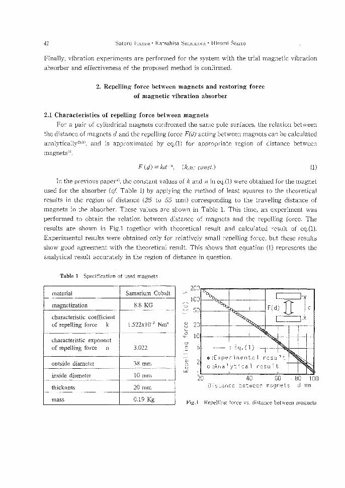
For a pair of cylindrical magnets confronted the same pole surfaces, the relation between
the distance of magnets d and the repelling force F(d) acting between magnets can be calculated
analytically2’・3), and is approximated by eq.(1) for appropriate region of distance between
rraagnets2>.
F(d)== led n.(勧ノconsの (1)
In the previous paperi}, the constant values of fe and n in eq.(1) were obtained for the magnet
used for the absorber (cf Table 1) by applying the method of least squares to the theoretical
results in the region of distance (25 to 55 mm) corresponding to the traveling distance of
magnets in the absorber. These values are shown in Table 1. This time, an experiment was
performed to obtain the relation between distance of magnets and the repelling force. The
results are shown in Fig.1 together with theoretical result and calculated result of eq.(1).
Experimenta]results were obtained only for relatively small repelling force, but these resuユts
show good agreement with the theoretical result. This shows that equation (1) represents the
analytical result accurately in the region of distance in question.
Table 1 Specification of used magnets
mateda1 Samarium Cobalt
官 ■高≠№獅?tlzatlo? 8.8KG
characteris重ic coeff重cient
潤orepe玉1圭ng fbrce k 1522x10帰3 Nmn
charac重er量stic exponent
盾? repelhng fbrce n 3,022
ou{side (至iameter 38mm
inside diame£er 10mm
thlc㎞ess 20mm
maSS 0.19Kg
z
℃ LL
Φり
。
鴇
⑰⊂:
’一
一ド①Q一
Φ
α
2ee
ユ00
so
2C
IG
5
2
/
F(d
m1・III:g:lld
: Eq.(1)
e:Experimenta1 result
o:Analytica] result ; l d
2D
Distance 40 60 ,8D IDObetween magnets d mm
Fig.1 Repe]ljng force vs. clistance between magnets
Study on a Magnetic Dynamic Vibration Absorber with Adjustable Natural Frequency 43
2.2 Nonlinear approximatien of restoring fonce and natural frequency of absorber
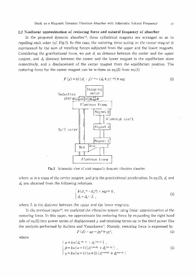
In the proposed dynamic absorberi), three cylindrical magnets are arranged so as to
repelling each other (cf Fig.2). ln this case, the restoring force acting on the center magnet is
represented by the sum of repelling forces subjected from the upper and the lower magnets.
Considering the gravitational force, we put di as distance between the center and the upper
magnet, and d2 distance between the center and the lower magnet in the equilibrium state
respectively, and y displacement of the center inagnet from the equilibrium position. The
restoring force for the center magnet can be written as eq.(2) from eq.(1).
F (y) == le { ( d, 一y) 一”一 (d2 +y) m”} + mg
Reduc ti on
gear
Ba11
on
StePPlng@motor
A}um雪num frame
凹agnet 8
Alu
凹agnet Arew
1
晒agnet c
Nut Arm
Alu崩numヂrame
A]uminum shaft
(2)
Fig.2 Schematic view of trial magnetic dynamic vibration absorber
where m is a mass of the center magnet, and g・is the gravitational acceleration. ln eq.(2), di and
d2 are obtained from the following relations.
( fed,(tid”, :一 di2 r) + nzg ., o ,
(3)
where L is the distance between the upper and the lower magnets.
In the previous paperi), we analyzed the vibration system using linear approximation of the
restoring force. ln this paper, we approximate the restoring force by expanding the right hand
side of eq.(2) into power series of displacement y and retaining terms up to the third power like
the analysis performed by Kojima and Yamakawa”}. Namely, restoring force is expressed by
F(d) == ay-6y 2十 7y 3, (4)
where
α請η{貯圏)+み(n+1)}, 灘‡1;灘欝ユ訴,} (・)
44 Satoru IGARAsi ’ Katsuhisa SHiBuKAwA ’ Hiromi Srs’Krro
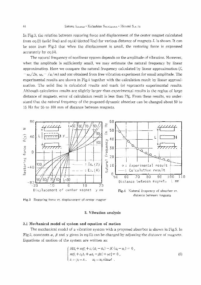
In Fig.3, the relation between restoriRg force aRd displacement of the center magnet calculated
from eq.(2) (solid line) and eq.(4) (dotted line) for various distance of magnets L is shown. lt can
be seen from Fig.3 that when the displacement is small, the restoring force is expressed
accurately by eq.(4).
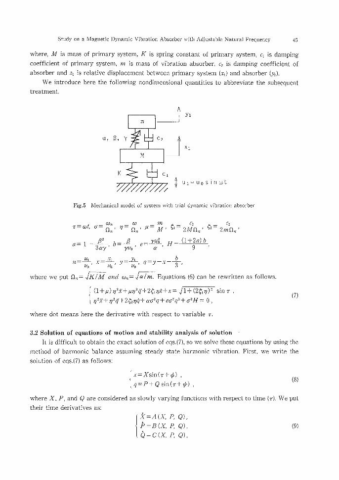
The natural frequency of nonlinear system depends on the amplitude of vibration. However,
when the amplitude is sufficiently small, we may estimate the natural frequency by linear
approximation. Here we compare the natural frequency calculated by linear approximatioR (f一
=wn/2z, bln一一 /a/m) and one obtained from free vibration experiment for small anitplitude. The
experimental results are shown in Fig.4 together with the calculation result by linear approxi-
ination. The solid line is calculated results and mark (o) represents experimental results.
Although calculation results are slightly larger than experimental results in the region of large
distance of magRets, error of calculation result is less than 70/o. From these results, we under-
stand that the natural frequency of the proposed dynamic absorber can be changed about 5e to
15 Hz for 55 to 100 mm of distance between magnets.
z
BD
h 40ご
g
ち o脳
9・[
B 一408匡
一80 -20 一10 Dfisplacement of
レ50 ’U0 70 ,’80 /
ノ!
L「’一一一一一
@一 一 一 一 聯 墜yγ
!
I90
ノチ100
’
100 !! 一 : Eq.(2)
@ 一 一 : Eq.(4) !m !
!
m ノ
.!
t0 ’
W0,’7060 L=50
O 10 20center magnet y mm
60N工
50ξ
〉,40茎
蜜30冨
レ
920偏
養10娼
z O 50
L φ
’
o = Experゴme自tal result
@: Calculation result
60 =フ0 80 90 ユ00 110
Dfistance between magnets L mm
Fig.4 Natural frequency of absorber vs.
distance between magnets
Fig.3 Restoring force vs. displacement of center magnet
3. Vibration analysis
3.1 Meehanical model of system and equation of motion
The rnechanical model of a vibration system with a proposed absorber is shown in Fig.5. ln
Fig.5, constants cr, B and 7 given in eq.(5) can be changed by adjusting the distance of magnets.
Equations of motion of the system are written as:
Mdr1+幅+01(£眼肉+1((κ1-zの=0,
mYl + c22i + azi 一B2?+ 7z?= O ,
Z玉=夕1-Xl, 祐二Z宛Slnω’,
(6)
Study on a Magnetic Dynamic Vibration Absorber with Adjustable Natural Frequency 45
where, M is rnass of primary system, K is spring constant of primary system, ci is damping
coefficient of primary system, m is mass of vibration absorber, c2 is damping coefficient of
absorber aRd zi is relative displacement between primary system (xi) and absorber (yi).
We introduce here the followiRg nondimensional quantities to abbreviate the subsequent
treatment.
oi, B,
n5
,Y C2
凹
K C1φ
/
Yl
Xl
ui== uosin tut
Fig.5 Mechanical model of system with trial dynamic vibration absorber
・畷・一絵・・一&!・一三炉2諺1Ω。・9・一2蒲!
・一1「鈴「告・・ぞH」÷1α)δ・
u:::一i2’一, x= m£.trmti , y=一elby, q=y-x一一III一,
where we put s).== v7?7iili一 and (it). = JE;7 E;一 Equations (6) can be rewritten as follows.
鵬磯鷲雛藩鑑亀η1:si
where dot means here the derivative with respect to variable T.
(7)
3。2So韮u毛ion of equations of拠otion a陰d stabiHty ana蓋ysis of solution
王tis difficult to obtai1}the exact solution of eqs.(7), so we solve these equations by using the
method of harmonic balance assuming steady state harmonic vibration. First, we write the
solution of eqs.(7)as follows:
{翻臨), (・)
where X, P, and Q are considered as slowly varying functions with respect to time(τ), We put
their tilne derivatives as:
x=.4(x,P,Q), {灘ぎ1 (・)
46 Satoru IGARAsi . Katsuhisa SHiBuKAwA ’ Hiromi SEKTTo
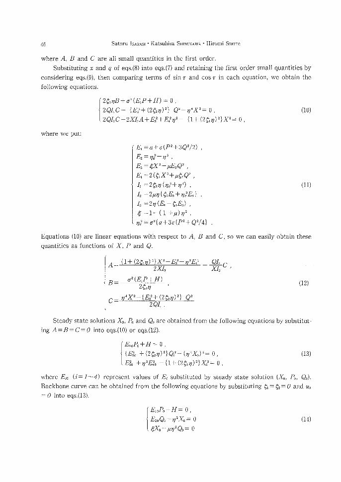
where A, B and C are all small quantities in the first order.
Substituting x and q of eqs.(8) into eqs.(7) and retaining the first order smal} quantities by
considering eqs.(9), then comparing terms of sin r and cos T in each equation, we obtain the
following equations.
{i聖駕』嵐)、}_。, (1・)
where we put:
Equations (le) are linear equations with respect to A
quantities as functions of X, P and Q.
Ei =a十e(P2十3Q2/2) ,
E2 = ope2-op 2 ,
E, = 4×2-ptE, Q2 ,
E, = 2(g, X2十 pt g, Q2 ,
4 =292n(ij,2十ty 2) ,
f2 =2pt op { g2 E3 十 rye2 E4 } ,
1, =2 ty (E, 一 e, E,) ,
e :1一 ( 1 一i一 pt) op 2 ,
op,2 = 02{a十3e (P2十 Q2/4} .
,B and C,
A== 2XI,
a2(EiP+H)B==一 2g, ry ’
一t{1一:d:一!lll (2 )}X E E
(11)
so we can e.asily obtain these
笠。・
(!2)
2QI, .
Steady state solutions Xo, Po and Qo are obtained from the following equations by substitut-
ing A=B= C =: 0 into eqs.(10) or eqs.(12).
{餓繰翻, (13)
where Eio (i一一ln-4) represent values of Ei substituted by steady state solution (Xo, Po, Qo).
Backbone curve can be obtained from the following equations by substituting gi : g2 =: 0 and orD
:0 into eqs.(13).
{綿織 (14)
Study on a Magnetic Dynamic Vibration Absorber with Adjustable Natural Freqaency 47
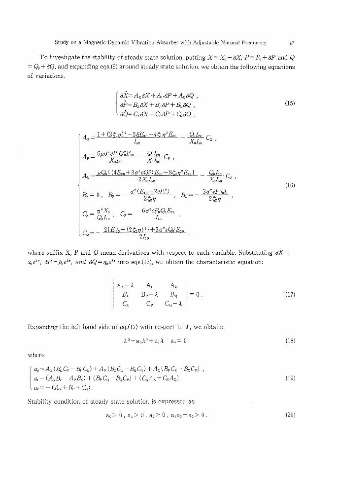
To investigate the stability of steady state solution, putting X =:: Xo 十 6X, P = Po 十 6P and Q
: Qo 十 6Q, and expanding eqs.(9) around steady state solution, we obtain the following equations
of variations.
謄艦齢 ・(15)
X一
@/30A・一h皷コ:c・・ 一一k!fthiww(lftkial.{(E 3 Q)E 8 E}
Qo120 Cx ,Xo130
AQ=: 2Xo130
玖一・・B・・=:一σ2(Ei e+2ePo2Q g, if)・B…=:
Cx一サ藷,ご・一一6σ26響・,
ww 2{E220÷(2C2 n)2}十3if2eQo2E20
2ム。
一象卸・
3σ2娼Qも
(16)
2 g, op ,
where suffix X, P and Q mean derivatives with respect to each variable. Substituting 6X =:
foeAT, 6P=:p,eir, and 6Q == qoeA’ into eqs.(15), we obtain the characteristic equation:
A,一a A, AQ Bx Bp m ft BQ
C, C, C,一!
=o. (17)
Expanding the left hand side of eq.(17) with respect to A, we obtain:
A3十a2A2十aiA十ao == O・
where
cft, :A, (B, C, 一 B, C,) 一Y A,) (B, C, 一B, C,) +A, (B,) C, 一B, C,) ,{
ai == (AxBp ww ApBx) + (Bp CQ ww BQ Cp) + (CQ Ax ww Cx AQ)
cz, = 一 (A, 一i一 B, 十 C,) .
Stability condition of steady state solution is expressed as:
ao> O, ai> O, a2> O, aia2-ao> O.
(18)
(19)
(20)
48 Satoru lc}ARtxs.i ’ Katsuhisa Si・msuKAwA ’ Hiromi Sm〈B’o
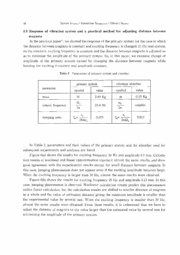
3.3 Response of vibration system and a practical method for adjusting distaRce between
magnets
In the previous paperi>, we showed the response of the primary system for the case in which
the distance between magnets ls constant and exciting frequency is changed. ln the reai system,
on the contrary, exciting frequency is constant and the distance between magnets is adjusted so
as to m面mize the amplitude of the primary system. SO, in this paper, we examine change of
amplitude of the primary system caused by changing the distance between magnets while
keeping the exciting frequency and amplitude constant.
Table 2 Parameters of primary system and absorber
.垂窒撃高≠窒凵@system Vibra重iOn abSOrber
parame重er symbol value symbol value
maSS M 249Kg m 0.19Kg
Ratural frequcncy
Ω、
R33,4Hz
ω轟
「variable
damping ratio C1ト1二@ 2MΩ n
0,023 c2ト2=@ 2mΩ 轟
0,0!5
In Table 2, parameters and their values of the primary system and the absorber used for
subsequent experiments and analyses are listed.
Figure 6(a) shows the results for exciting frequency 30 Hz and amplitude O.1 mm. Calcula-
tion results of nonlinear and linear approximation represent almost the same results, and show
good agreement with the experimental results except for small distance between magnets. ln
this case, jumping phenomenon does not appear even if the exciting amplitude becomes large.
When the exciting frequency is larger than 30 Hz, almost the same results were ebtained.
Figure 6(b) shows the results for exciting frequency 25 Hz and amplitude O.15 mm. ln this
case, jumping phenomenon is observed. Nonlinear calculation results predict this phenomenori
unlike linear calculation, but the calculation results are shifted to smaller distance of magnets
as a whole and the value of estimated distance giving the minimum amplitude is smaller than
the experimental value by several mm. When the exciting frequency is smaller than 30 Hz,
almost the same results were obtained. From these results, it is understand that we have to
adjust the distance of magnets to the value larger than the estimated value by several mm for
minimizing the amplitude ef the primary system.
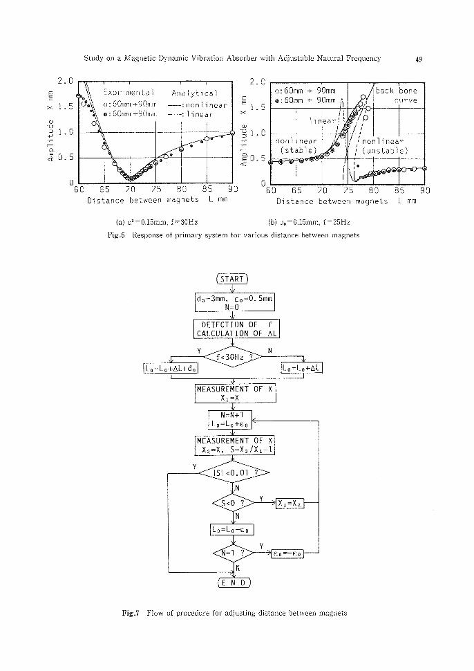
Study on a Magnetic Dynamic Vibration Absorber with Adjustable N’atural Frequency 49
2.o
EE
× L5
Φ
つ⊃1』ポ
三ξ0.5
D
ぴ
亀σ
o:60mm→・90rnm
?:60mmく一90rnm
@ i }
一・・一・ P1near:non}唯1、ear.
D }
o
9
o
60 65 フ〔} フS 80 85 90
Distance between magnets し mm
2.O
EE1.5×
ゆ
9ユ.o:ゴ
ド書O.5く
。
o=60mm →・ 90m揃
?:60r翼m ・← 90田m 声
back bone
@ curve
hnearμ
弓
@8@ρ7!
nOnbnearistable)
’ 監
f 匪
C
’
R ε
@ノ
’non]1neariunstab達e)
「④_1
SO 65 フ〔〕 フ5 8〔〕 85 90
Distance between magnets L mm
(a) uO =O.15mm, f=30Hz (b) uo=O.15mm, f== 251’lz
Fig.6 Response of primary systena for various distance between magnets
START
do=3mm, eo=O.5mm N漏0
D[TECTION OF fCAしCULATIO卜1 0F △L
Y N
f〈30Hz ?
to=Lo十AL十de Lo=Lo十AL
MEASgR[MENT OF X X1讐X
N・・N+1
Lo==Lo+Eo
MEASUREMENT OF XX,=x, S=X,IX,一1
YISI 〈O. Ol 2
’.].N
Y s〈o ? Xl”X2
N
Lo=:Lo’ge
Y=1 ?
Eo”一eo
N
END
Fig.7 Flow of procedure for adjusting distance between magnets
50 Satoru IGARAsl ’ Katsuhisa Sl-IIBuKAwA ’ }i{iromi SEI〈u’o
However, the amplitude of the primary system is sufficiently small in the vicinity of
distance of magnets giving the minimum amplitude in any case, so we only need to set the
distance between magnets at almost the minimum position.
Referring these results, we propose here a practical adjusting method for the proposed
absorber to give almost the minimum amplitude. ln this method, we first set the distance atthe
value near the minimum position. Namely, when the exciting frequency is larger than 30 Hz, we
set the distance at the value calculated by linear approximation, and wheR the exciting fre-
quency is smaller thaR 30 Hz, we set the distance at slightly larger value than linear estimation.
Then we search the minimum position with moving the magnets by srnall distance while
observing the amplitude of the primary system. Flow of this procedure is shown in Fig.7.
4. Vibration experimeRt for a systerrt witk a trial
magnetic dynamic vibration absorber
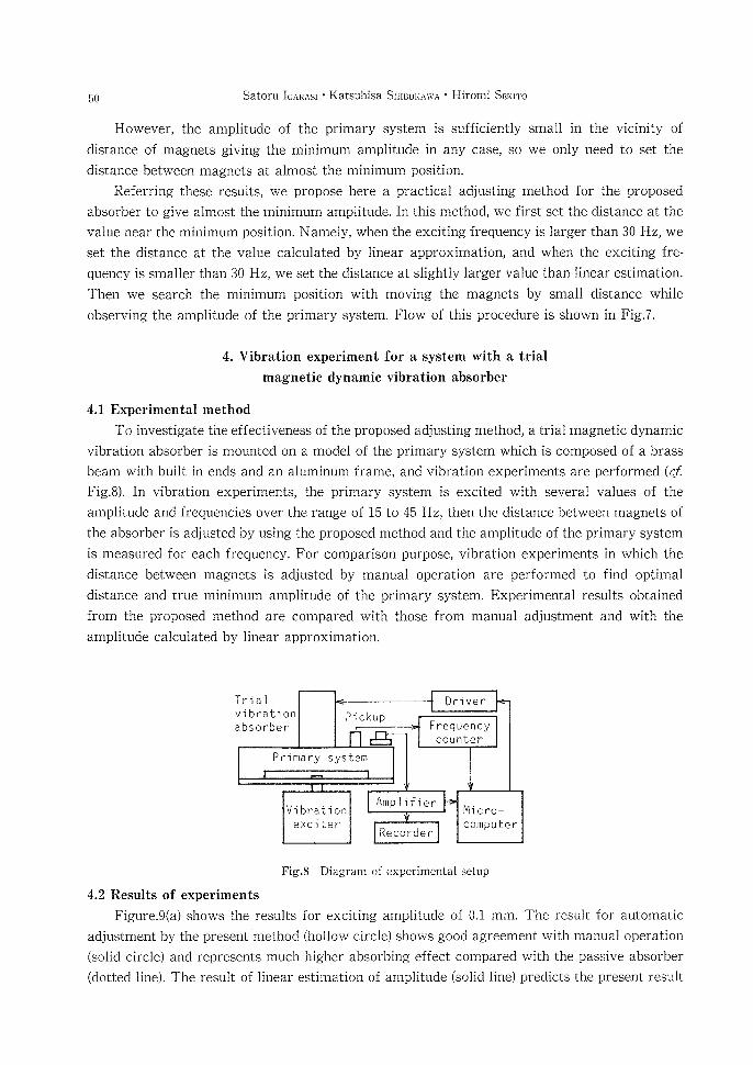
4.1 Experimental method
To investigate the effectiveness of the proposed adjusting method, a trial magnetic dynamic
vibration absorber is mounted on a model of the primary system which is composed of a brass
beam with built in ends and an aluminum frame, and vibration experiments are performed (cf
Fig.8). ln vibration experiments, the primary system is excited with several values of the
amplitude and frequencies over the range of 15 to 45 Hz, then the distance between magnets of
the absorber is adjusted by using the proposed method and the amplitude of the primary system
is measured for each frequency. For comparison purpose, vibration experiments in which the
distance between magnets is adjusted by manual operation are performed to find optimal
distance and true minimum amplitude of the primary system. Experimental results obtained
from the proposed method are compared with those from manual adjustment and with the
amplitude calculated by linear approximation.
Trialvibrationabsorber
Pickup
Primary system
Dni ver
Frequencycounter
Vi bra ti on
exciter
Amp]ifier
Recorder
醐cro-computer
Fig.8 Diagram of experimental setup
4.2 Results of experiments
Figure.9(a) shows the results for exciting amplitude of O.1 mm. The result for automatic
adjustment by the present ’method (hollow circle) shows good agreement with nianual operation
(solid circle) aRd represents much higher absorbing effect compared with the passive absorber
(dotted line). The result of linear estimation of amplitude (solid line) predicts the present result
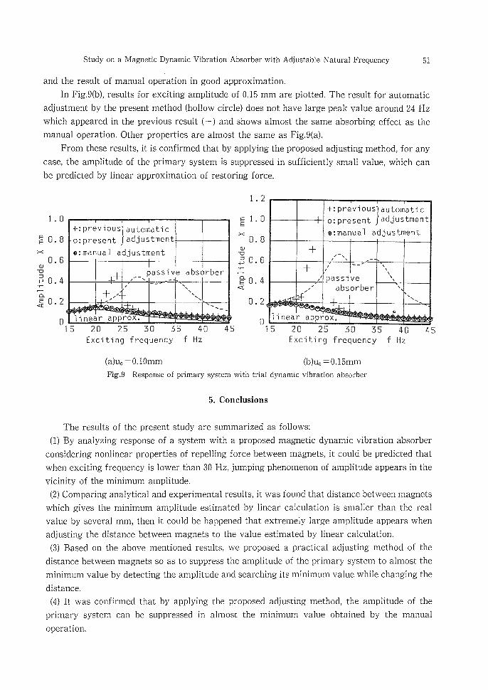
Study on a Magnetic Dynamic Vibration Absorber with Adjustable Natural Frequency 51
and the result of manual operation in good approximation.
In Fig.9(b), results for exciting amplitude of O.15 mm are plotted. The result for automatic
adjustment by the present method (hollow circle) does not have large peak value around 24 Hz
which appeared in the previous result (十) and shows almost the same absorbing effect as the
manual operation. Other properties are almost the same as Fig.9(a).
From these results, it is confirmed that by applying the proposed adjusting method, for any
case, the amplitude of the primary system is suppressed in sufficiently small value, which can
be predicted by linear approximation of restoring force.
E
×
ユ.0
O.8
O.6名
BO.4ニ
ロ左0・2
o
一←:previOUS autornatic
E=P・esent adjustmen七
G=rれanual adjustment
十 !!、 A 一
passive absorber
十/ ’
!、 一
、、
@、@ 、@ 、@ 、
、 、
@、 鴨 、
1inear aPP!(ox顧
IS 20 25 3g 55 40Exciting frequency f Hz
45
ユ。2
E 1.OE
× O.8
名
w= O.6
二
go.4く
O.2
o
■{:prev、ous auto田atlCadjustment
o:present⑱=manua1 adjus七ment
十!、 A
ノ 、 ’
十、 一 !
、、
、
,垂≠唐唐撃魔、、
ノ absorber 、
’ 千、、
@、@ 、
o
1ine群 approx.玉5 20 25 50 55 4e
Exciting frequency f Hz
45
(a)uo=O.10mm (b)uo=O.15mmFig.9 Response of primary system with trial dynamic vibration absorber
5. Conclusions
The results of the present study are summarized as follows:
(1) By analyzing response of a system with a proposed magnetic dynamic vibration absorber
considering nonlinear properties of repelling force between magnets, it could be predicted that
when exciting frequency is lower than 30 gz, jumping phenomenon of amplitude appears in the
vicinity of the minimum amplitude.
(2) Comparing analytical and experimental results, it was found that distance between magnets
which gives the minimum amplitude estimated by linear calculation is smaller than the real
value by several mm, then it could be happened that extremely large amplitude appears when
adjusting the distance betweeR magnets to the value estimated by linear calculation.
(3) Based on the above mentioned results, we proposed a practical adjusting method of the
distance between magnets so as to suppress the an)plitude of the primary system to almost the
minimum value by detecting the amplitude and searching its minimum value while changing the
distance.
(4) lt was confirmed that by applying the proposed adjusting method, the amplitude of the
primary system can be suppressed in almost the minimum value obtained by the manual
operation.
52 Satoru IGAi{Asi ’ Katsuhisa Sf“BuKAwA ’ Hiromi SexiTo
Acknowledgments
The authors wish to thank Mr. Seiji Nakatani (graduate student of Hokkaido University,
now NEC Corporation) for his assistance in the experimental work, and Mr. Mamoru Tanaka
(General Manager of Manufacturing Engineering Laboratory in NIPPON SEIKO K. K.) for his
helpful advice and support on the manufacturing the trial magnetic dynamic vibration absorber.
References
1) S. lgarashi, K. Shibul〈awa, S. Nakatani and H. Sekito: Bull. Fac. Eng. Hokkaido Univ., 156
(1991) 29.
2) 1. Yamakawa and K. Shibata: 」. Japan Soc. Precision Eng., 38, 12 (!972) 1030.
3) E. Takeyama: Theory of Electromagnetic Phenomena, Maruzen (Tokyo) (1963) 246-308.
4) K. Kojima and 1. Yamakawa: 」. Japan Soc. Precision Eng., 47, 5 (1981) 568.