Embed Size (px)
Citation preview
�������
�����
������������������������������
��������
����������� ����
�
��������������� �
����������������
������������������
�������������� �
���������������� �
�������������
�����������
���� �� ����� � ��������
��������������
����������
�����������
��������������
�����������
����������
��������
�����������������
��������
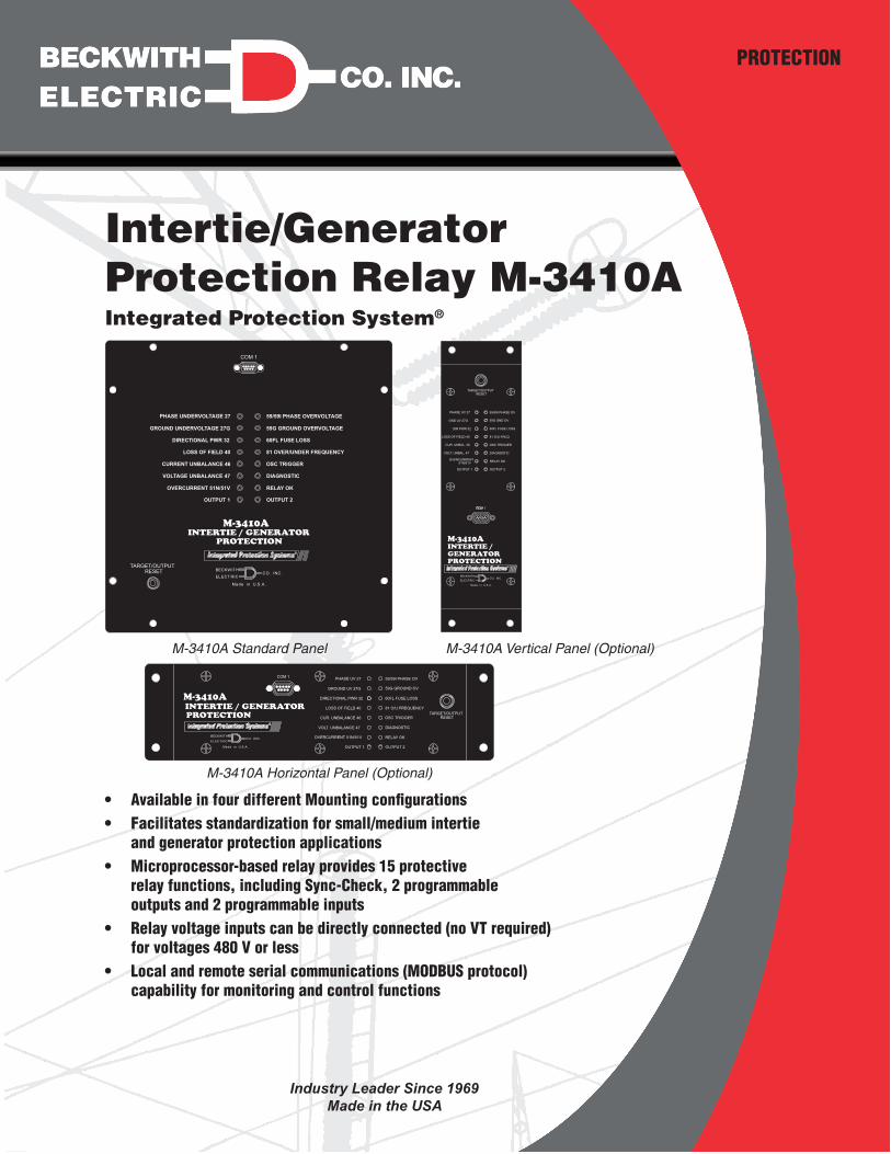
Intertie/Generator Protection Relay M‑3410A
PROTECTION
• Available in four different Mounting configurations • Facilitates standardization for small/medium intertie
and generator protection applications • Microprocessor-based relay provides 15 protective
relay functions, including Sync-Check, 2 programmable outputs and 2 programmable inputs
• Relay voltage inputs can be directly connected (no VT required) for voltages 480 V or less
• Local and remote serial communications (MODBUS protocol) capability for monitoring and control functions
Integrated Protection System®
���������������
��������
�������
��������
���������
�����������
��������������
����������
����������������
����������
������
�� ����
���� � ���
� �
�������������������
�������
����
���������
��������
������������
������
����������
���������
����������
�����������
������������������
�
M‑3410A Vertical Panel (Optional)
M‑3410A Horizontal Panel (Optional)
�����
��������
��������
������������������������������
���������� �������
�� �� ����� �
��� ����
�������
�
��������������������
���������������� ����
���������������� ����
���������������
���������������
�������������������
����� ��������������
��������
������ ��
��������������������� �
�����������������������
��������������
�� � ��������������� �
��������
��������
�� �����
M‑3410A Standard Panel
Industry Leader Since 1969Made in the USA

–2–
M‑3410A Intertie/Generator Protection Relay
This Page Left Intentionally Blank
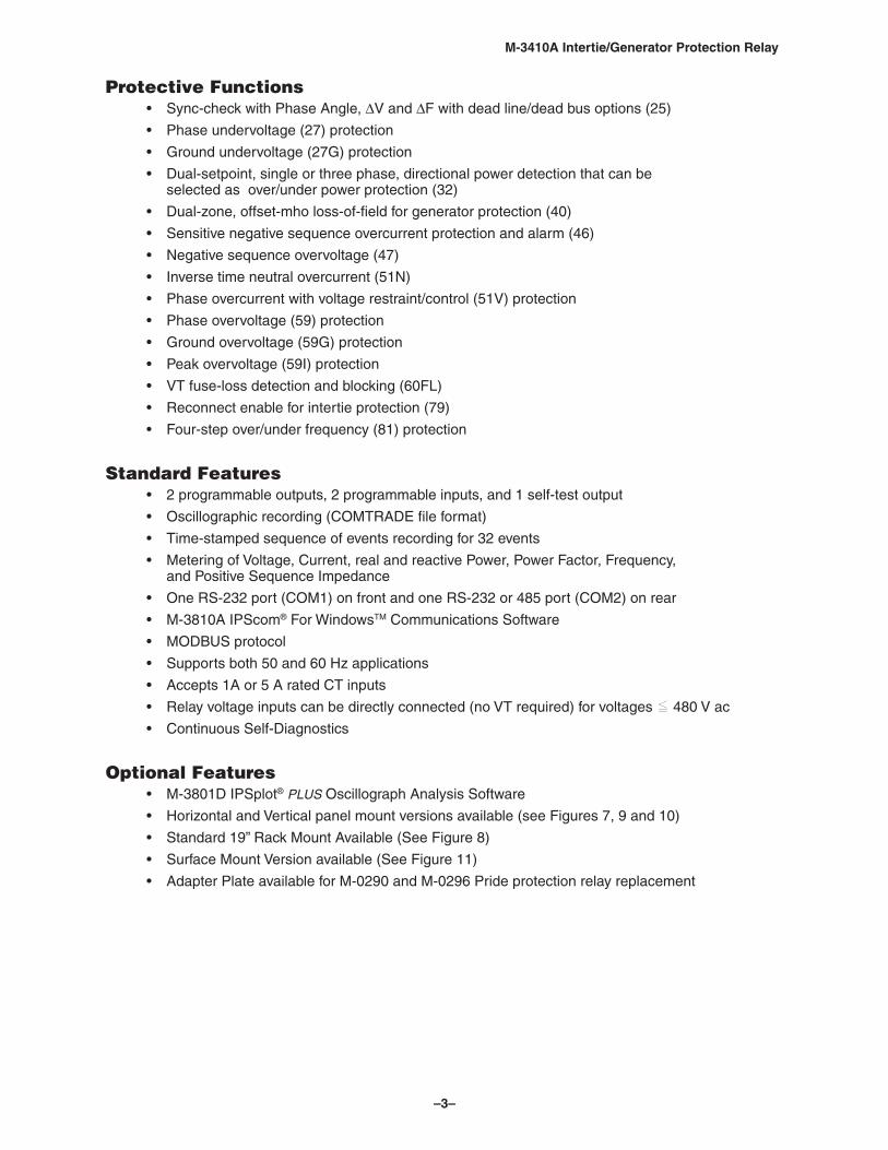
–3–
M‑3410A Intertie/Generator Protection Relay
Protective Functions • Sync-check with Phase Angle, ∆V and ∆F with dead line/dead bus options (25)
• Phase undervoltage (27) protection
• Ground undervoltage (27G) protection
• Dual-setpoint, single or three phase, directional power detection that can be selected as over/under power protection (32)
• Dual-zone, offset-mho loss-of-field for generator protection (40)
• Sensitive negative sequence overcurrent protection and alarm (46)
• Negative sequence overvoltage (47)
• Inverse time neutral overcurrent (51N)
• Phase overcurrent with voltage restraint/control (51V) protection
• Phase overvoltage (59) protection
• Ground overvoltage (59G) protection
• Peak overvoltage (59I) protection
• VT fuse-loss detection and blocking (60FL)
• Reconnect enable for intertie protection (79)
• Four-step over/under frequency (81) protection
Standard Features • 2 programmable outputs, 2 programmable inputs, and 1 self-test output
• Oscillographic recording (COMTRADE file format)
• Time-stamped sequence of events recording for 32 events
• Metering of Voltage, Current, real and reactive Power, Power Factor, Frequency, and Positive Sequence Impedance
• One RS-232 port (COM1) on front and one RS-232 or 485 port (COM2) on rear
• M-3810A IPScom® For WindowsTM Communications Software
• MODBUS protocol
• Supports both 50 and 60 Hz applications
• Accepts 1A or 5 A rated CT inputs
• Relay voltage inputs can be directly connected (no VT required) for voltages O 480 V ac
• Continuous Self-Diagnostics
Optional Features • M-3801D IPSplot® PLUS Oscillograph Analysis Software
• Horizontal and Vertical panel mount versions available (see Figures 7, 9 and 10)
• Standard 19” Rack Mount Available (See Figure 8)
• Surface Mount Version available (See Figure 11)
• Adapter Plate available for M-0290 and M-0296 Pride protection relay replacement
–4–
M‑3410A Intertie/Generator Protection Relay
Values in parentheses apply to 1 A CT secondary rating.
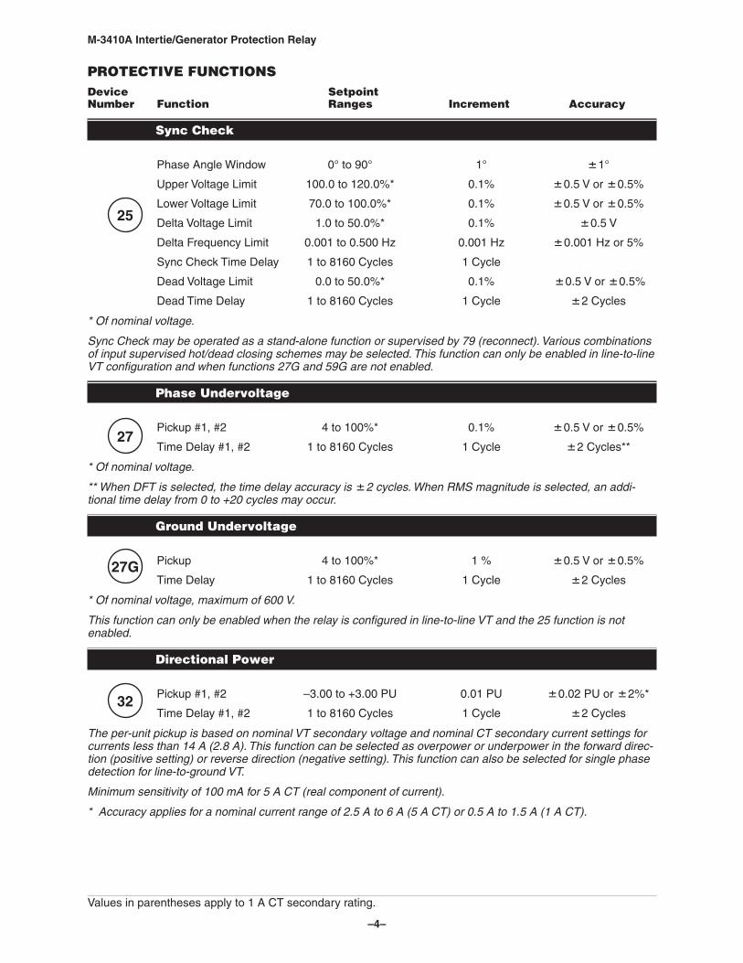
PROTECTIVE FUNCTIONSDevice Setpoint Number Function Ranges Increment Accuracy
Sync Check
Phase Angle Window 0° to 90° 1° 1°
Upper Voltage Limit 100.0 to 120.0%* 0.1% 0.5 V or 0.5%
Lower Voltage Limit 70.0 to 100.0%* 0.1% 0.5 V or 0.5%
Delta Voltage Limit 1.0 to 50.0%* 0.1% 0.5 V
Delta Frequency Limit 0.001 to 0.500 Hz 0.001 Hz 0.001 Hz or 5%
Sync Check Time Delay 1 to 8160 Cycles 1 Cycle
Dead Voltage Limit 0.0 to 50.0%* 0.1% 0.5 V or 0.5%
Dead Time Delay 1 to 8160 Cycles 1 Cycle 2 Cycles
* Of nominal voltage.
Sync Check may be operated as a stand‑alone function or supervised by 79 (reconnect). Various combinations of input supervised hot/dead closing schemes may be selected. This function can only be enabled in line‑to‑line VT configuration and when functions 27G and 59G are not enabled.
Phase Undervoltage
Pickup #1, #2 4 to 100%* 0.1% 0.5 V or 0.5%
Time Delay #1, #2 1 to 8160 Cycles 1 Cycle 2 Cycles**
* Of nominal voltage.
** When DFT is selected, the time delay accuracy is 2 cycles. When RMS magnitude is selected, an addi‑tional time delay from 0 to +20 cycles may occur.
Ground Undervoltage
Pickup 4 to 100%* 1 % 0.5 V or 0.5%
Time Delay 1 to 8160 Cycles 1 Cycle 2 Cycles
* Of nominal voltage, maximum of 600 V.
This function can only be enabled when the relay is configured in line‑to‑line VT and the 25 function is not enabled.
Directional Power
Pickup #1, #2 –3.00 to +3.00 PU 0.01 PU 0.02 PU or 2%*
Time Delay #1, #2 1 to 8160 Cycles 1 Cycle 2 Cycles
The per‑unit pickup is based on nominal VT secondary voltage and nominal CT secondary current settings for currents less than 14 A (2.8 A). This function can be selected as overpower or underpower in the forward direc‑tion (positive setting) or reverse direction (negative setting). This function can also be selected for single phase detection for line‑to‑ground VT.
Minimum sensitivity of 100 mA for 5 A CT (real component of current).
* Accuracy applies for a nominal current range of 2.5 A to 6 A (5 A CT) or 0.5 A to 1.5 A (1 A CT).
25
27
32
27G
–5–
M‑3410A Intertie/Generator Protection Relay
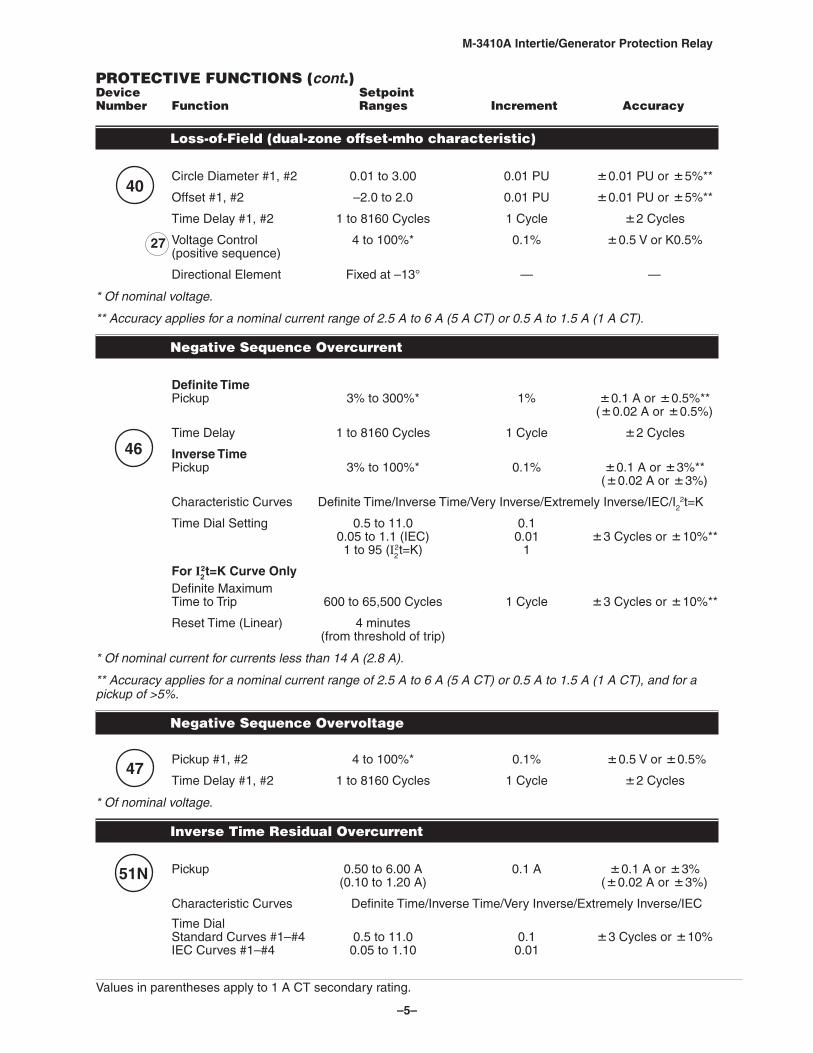
PROTECTIVE FUNCTIONS (cont.)Device Setpoint Number Function Ranges Increment Accuracy
Loss‑of‑Field (dual‑zone offset‑mho characteristic)
Circle Diameter #1, #2 0.01 to 3.00 0.01 PU 0.01 PU or 5%**
Offset #1, #2 –2.0 to 2.0 0.01 PU 0.01 PU or 5%**
Time Delay #1, #2 1 to 8160 Cycles 1 Cycle 2 Cycles
Voltage Control 4 to 100%* 0.1% 0.5 V or K0.5% (positive sequence)
Directional Element Fixed at –13° — —
* Of nominal voltage.
** Accuracy applies for a nominal current range of 2.5 A to 6 A (5 A CT) or 0.5 A to 1.5 A (1 A CT).
Negative Sequence Overcurrent
Definite Time Pickup 3% to 300%* 1% 0.1 A or 0.5%** (0.02 A or 0.5%)
Time Delay 1 to 8160 Cycles 1 Cycle 2 Cycles
Inverse Time Pickup 3% to 100%* 0.1% 0.1 A or 3%** (0.02 A or 3%)
Characteristic Curves Definite Time/Inverse Time/Very Inverse/Extremely Inverse/IEC/I22t=K
Time Dial Setting 0.5 to 11.0 0.1 0.05 to 1.1 (IEC) 0.01 3 Cycles or 10%** 1 to 95 (I2
2t=K) 1
For I22t=K Curve Only
Definite Maximum Time to Trip 600 to 65,500 Cycles 1 Cycle 3 Cycles or 10%**
Reset Time (Linear) 4 minutes (from threshold of trip)
* Of nominal current for currents less than 14 A (2.8 A).
** Accuracy applies for a nominal current range of 2.5 A to 6 A (5 A CT) or 0.5 A to 1.5 A (1 A CT), and for a pickup of >5%.
Negative Sequence Overvoltage
Pickup #1, #2 4 to 100%* 0.1% 0.5 V or 0.5%
Time Delay #1, #2 1 to 8160 Cycles 1 Cycle 2 Cycles
* Of nominal voltage.
Inverse Time Residual Overcurrent
Pickup 0.50 to 6.00 A 0.1 A 0.1 A or 3% (0.10 to 1.20 A) (0.02 A or 3%)
Characteristic Curves Definite Time/Inverse Time/Very Inverse/Extremely Inverse/IEC
Time Dial Standard Curves #1–#4 0.5 to 11.0 0.1 3 Cycles or 10% IEC Curves #1–#4 0.05 to 1.10 0.01
Values in parentheses apply to 1 A CT secondary rating.
47
46
51N
27
40
–6–
M‑3410A Intertie/Generator Protection Relay
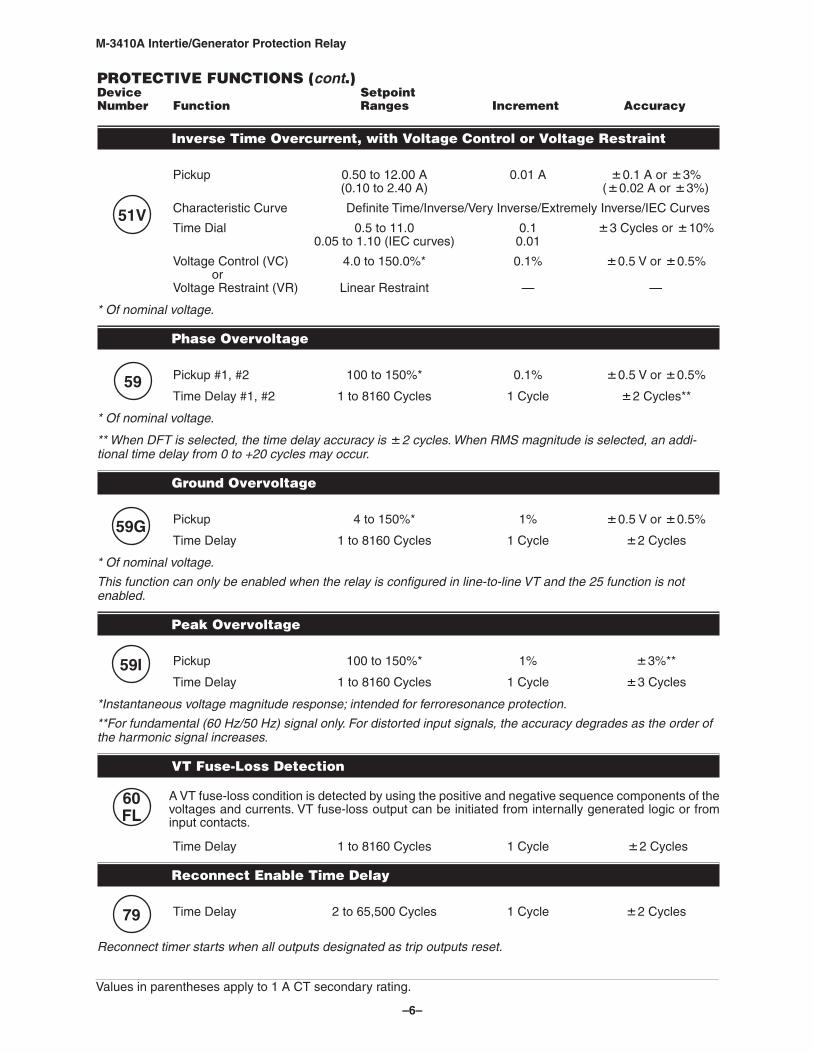
PROTECTIVE FUNCTIONS (cont.)Device Setpoint Number Function Ranges Increment Accuracy
Inverse Time Overcurrent, with Voltage Control or Voltage Restraint
Pickup 0.50 to 12.00 A 0.01 A 0.1 A or 3% (0.10 to 2.40 A) (0.02 A or 3%)
Characteristic Curve Definite Time/Inverse/Very Inverse/Extremely Inverse/IEC Curves
Time Dial 0.5 to 11.0 0.1 3 Cycles or 10% 0.05 to 1.10 (IEC curves) 0.01
Voltage Control (VC) 4.0 to 150.0%* 0.1% 0.5 V or 0.5% or Voltage Restraint (VR) Linear Restraint — —
* Of nominal voltage.
Phase Overvoltage
Pickup #1, #2 100 to 150%* 0.1% 0.5 V or 0.5%
Time Delay #1, #2 1 to 8160 Cycles 1 Cycle 2 Cycles**
* Of nominal voltage.
** When DFT is selected, the time delay accuracy is 2 cycles. When RMS magnitude is selected, an addi‑tional time delay from 0 to +20 cycles may occur.
Ground Overvoltage
Pickup 4 to 150%* 1% 0.5 V or 0.5%
Time Delay 1 to 8160 Cycles 1 Cycle 2 Cycles
* Of nominal voltage.
This function can only be enabled when the relay is configured in line‑to‑line VT and the 25 function is not enabled.
Peak Overvoltage
Pickup 100 to 150%* 1% 3%**
Time Delay 1 to 8160 Cycles 1 Cycle 3 Cycles
*Instantaneous voltage magnitude response; intended for ferroresonance protection.
**For fundamental (60 Hz/50 Hz) signal only. For distorted input signals, the accuracy degrades as the order of the harmonic signal increases.
VT Fuse‑Loss Detection
A VT fuse-loss condition is detected by using the positive and negative sequence components of the voltages and currents. VT fuse-loss output can be initiated from internally generated logic or from input contacts.
Time Delay 1 to 8160 Cycles 1 Cycle 2 Cycles
Reconnect Enable Time Delay
Time Delay 2 to 65,500 Cycles 1 Cycle 2 Cycles
Reconnect timer starts when all outputs designated as trip outputs reset.
79
60FL
59I
59
51V
59G
Values in parentheses apply to 1 A CT secondary rating.
–7–
M‑3410A Intertie/Generator Protection Relay
81
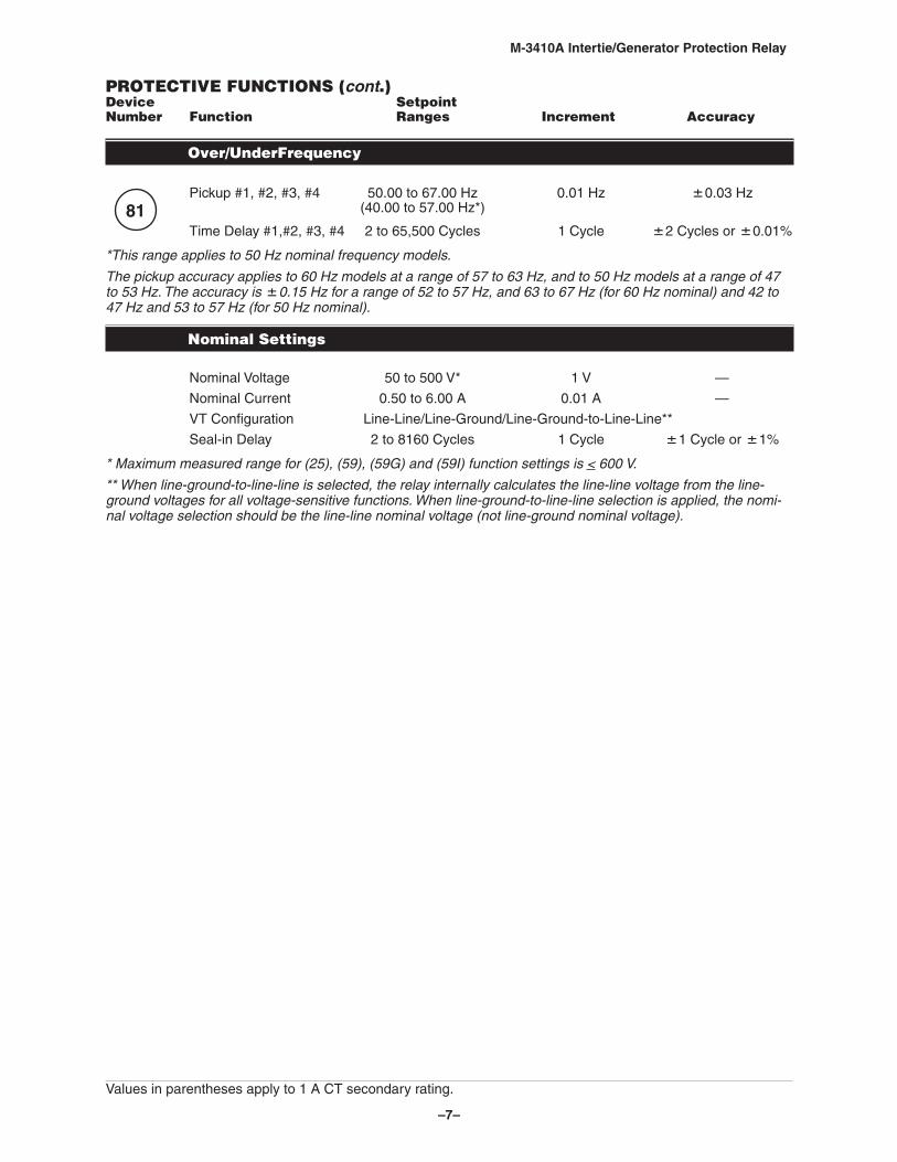
PROTECTIVE FUNCTIONS (cont.)Device Setpoint Number Function Ranges Increment Accuracy
Over/UnderFrequency
Pickup #1, #2, #3, #4 50.00 to 67.00 Hz 0.01 Hz 0.03 Hz (40.00 to 57.00 Hz*)
Time Delay #1,#2, #3, #4 2 to 65,500 Cycles 1 Cycle 2 Cycles or 0.01%
*This range applies to 50 Hz nominal frequency models.
The pickup accuracy applies to 60 Hz models at a range of 57 to 63 Hz, and to 50 Hz models at a range of 47 to 53 Hz. The accuracy is 0.15 Hz for a range of 52 to 57 Hz, and 63 to 67 Hz (for 60 Hz nominal) and 42 to 47 Hz and 53 to 57 Hz (for 50 Hz nominal).
Nominal Settings
Nominal Voltage 50 to 500 V* 1 V —
Nominal Current 0.50 to 6.00 A 0.01 A —
VT Configuration Line-Line/Line-Ground/Line-Ground-to-Line-Line**
Seal-in Delay 2 to 8160 Cycles 1 Cycle 1 Cycle or 1%
* Maximum measured range for (25), (59), (59G) and (59I) function settings is < 600 V.
** When line‑ground‑to‑line‑line is selected, the relay internally calculates the line‑line voltage from the line‑ground voltages for all voltage‑sensitive functions. When line‑ground‑to‑line‑line selection is applied, the nomi‑nal voltage selection should be the line‑line nominal voltage (not line‑ground nominal voltage).
Values in parentheses apply to 1 A CT secondary rating.
–8–
M‑3410A Intertie/Generator Protection Relay
DescriptionThe M-3410A Intertie/Generator Protection Relay is intended for the protection of the intertie between the utility and dispersed generation. It is also suitable for the protection of synchronous and induction generators. Communications and control features of the M-3410A are accomplished utilizing the M-3810A IPScom® For WindowsTM Communications Software.
MeteringThe relay provides metering of voltages, currents, real power, reactive power, power factor, frequency and positive sequence impedance.
Metering Accuracies are:
Voltage: 0.5 V or 0.5%, whichever is greater (Range 0 to 600 V)
Current: 5 A rating, 0.1 A or 3%, whichever is greater (Range 0 to 14 A) 1 A rating, 0.02 A or 3%, whichever is greater (Range 0 to 2.8 A)
Power: 0.02 PU or 2%, whichever is greater
Frequency: 0.03 Hz (from 57 to 63 Hz for 60 Hz models; from 47 to 53 Hz for 50 Hz models)
Oscillographic RecorderThe oscillographic recorder provides comprehensive data recording of all monitored waveforms, input contacts and output contacts, storing up to 120 cycles of data. The total record length is configured for one or two partitions. A programmable post trigger delay (5 to 95%) is incorporated to capture breaker operation. The oscillograph is triggered either remotely using the serial interface, or designated status input signals or M-3410A programmable output operations. Storage of oscillographic records is nonvolatile, and will be retained even without power, as long as the on-board battery is healthy.
Oscillographic data can be downloaded using serial communication in Common Format For Transient Data Exchange (COMTRADE) format as specified by IEEE Standard C37.111-1999.
Sequence of EventsA total of 32 nonvolatile events can be stored. The recorded information includes the function(s) operated, the function(s) picked up, input/output contact status and time stamp. The events can be retrieved through the communications port. After the 32nd event is stored, additional events result in the oldest event being dropped (FIFO). The information is time-stamped to 1 ms resolution.
CalculationsCurrent and Voltage Values: Uses discrete Fourier transform (DFT) algorithm on sampled (32 times per cycle) voltage and current signals to extract fundamental frequency phasors for calculations. The 59/27 function, when set for RMS measurement, uses a time domain algorithm to calculate the voltage magnitude.
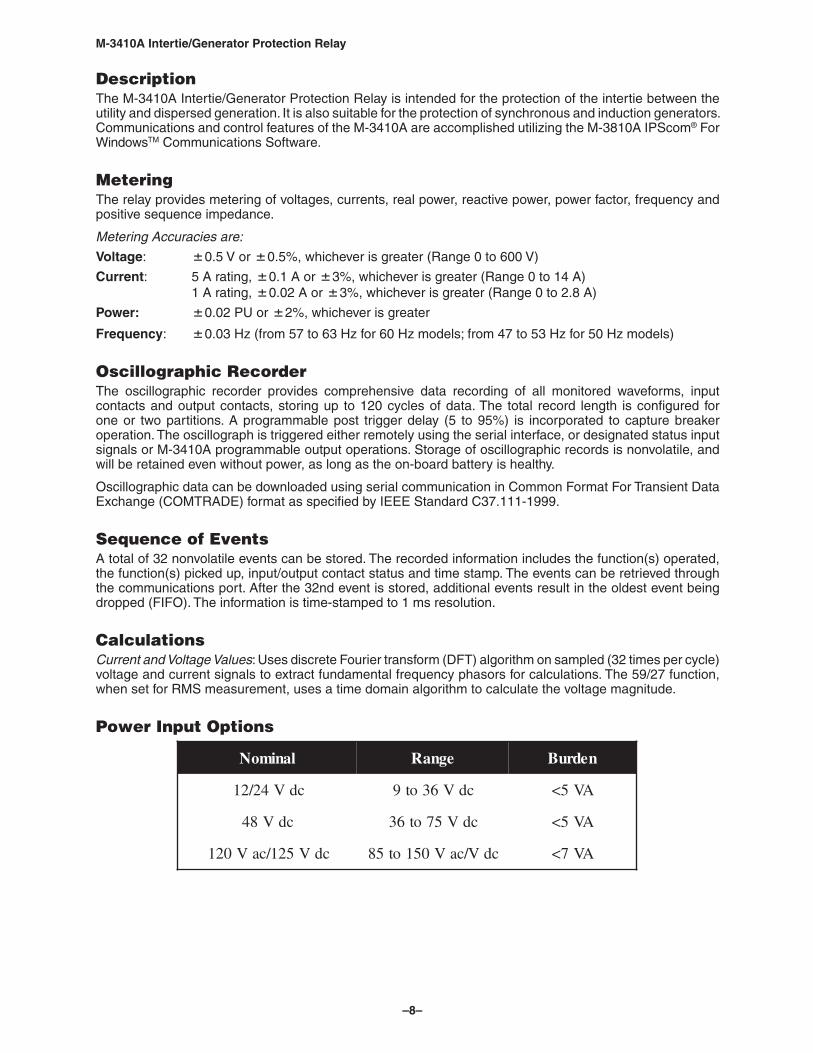
Power Input Options
lanimoN egnaR nedruB
cdV42/21 cdV63ot9 AV5<
cdV84 cdV57ot63 AV5<
cdV521/caV021 cdV/caV051ot58 AV7<
–9–
M‑3410A Intertie/Generator Protection Relay
Sensing Inputs 3 Voltage Inputs: Rated nominal voltage of 69 V ac to 480 V ac, 60 Hz (50 Hz user configurable). Will withstand 600 V continuous voltage. Source voltages may be line-to-ground or line-to-line connected. Phase sequence ABC/ACB is selectable. Voltage transformer burden less than 0.25 VA at 120 V ac.
3 Current Inputs: Rated current (IR) of 5.0 A or 1.0 A, 60 Hz (50 Hz user configurable). Will withstand 2IR continuous current and 30 IR for 2 seconds. Current transformer burden is less than 0.75 VA at 5 A for 5 A inputs, 0.3 VA at 1 A for 1 A inputs.
Control/Status InputsThe control/status inputs, INPUT1 and INPUT2, can be programmed to block any of the M-3410A functions and trigger the oscillograph recorder. The control/status inputs accept only dry contacts and are internally wetted (9 V dc) by the relay’s power supply. A minimum current of 1.3 mA is required to avoid spurious triggering of the input.
Output ContactsThe two programmable output relays, each with a contact are rated as per ANSI/IEEE C37.90-1989 for tripping: make 30 A for 0.2 seconds. Available hardware configurations include two normally open (Option B1), one normally open and one normally closed (Option B2), or two normally closed (Option B3) contacts. The contacts will carry 8 A, break 6 A at 120 V ac, break 0.1 A at 125 V dc, inductive break 0.1 A. Also provided is a self-test alarm output contact (form ‘c’) with a rating of 8 A at 120 V ac, 5 A at 30 V dc, 125 V dc 0.15 A resistive, 0.1 A inductive.
Any of the M-3410A protective functions can be individually programmed to activate the two programmable outputs. The user can configure the two programmable outputs to either energize or de-energize to issue an output command.
The outputs (excluding the self-test) can have two modes of operation, LATCHING and NORMAL. The LATCHING mode requires an operator intervention to deactivate the outputs after the condition for operation has been removed. In the NORMAL mode, when the condition for tripping has been removed, the output(s) will deactivate automatically after the corresponding seal-in timers have expired.
Target/Status Indicators and ControlsThe RELAY OK LED reveals proper cycling of the microprocessor. The DIAGNOSTIC LED provides indication of the error code (when flashing). The OSC TRIGGER LED indicates that the oscillograph has been triggered. The remaining eleven LEDs are used to indicate which protective function(s) have been tripped. OUTPUT 1 and OUTPUT 2 are used to indicate the status of the output contacts. The output LEDs will illuminate when the output contact relays are tripped. The TARGET/OUTPUT RESET button resets the target LEDs if the conditions causing the operation have been removed. Holding the TARGET/OUTPUT RESET button displays the present pickup status of the M-3410A functions. The TARGET/OUTPUT RESET button will deactivate the tripped output contact if the LATCHING mode was selected. (If the seal in timer has already expired, the output contact will deactivate immediately.)
CommunicationCommunications ports include a front panel RS-232 port and a rear port user configurable to RS-232 or RS-485. The RS-232 ports are connected physically with a DB-9 connector and the RS-485 port utilizes 4-wire interface mounting screw terminals.
M-3810A IPScom® For WindowsTM Communications Software utilizing the MODBUS communications protocol in RTU mode, implements serial, byte-oriented asynchronous communication with the M-3410A and provides the following functions: • Interrogation and modification of setpoints
• Time-stamped sequence of events information for the 32 most recent events
• Real-time metering of all quantities measured
• Downloading of recorded oscillographic data
• Relay Setup
–10–
M‑3410A Intertie/Generator Protection Relay
Tests and StandardsThe M-3410A Generator/Intertie Protection Relay complies with the following type tests and standards:
Voltage Withstand
Dielectric WithstandAll terminals except power supply and status input contacts, 2500 V ac/3500 V dcPower Supply and Status Input Contacts:IEC 60255-5 1,500 V dc for power supply voltages (12, 24, 48 V inputs) 2500 V ac/3500 V dc for power supply voltages (120 V ac/125 V dc input)
Impulse VoltagePower Supply Input Voltages, 120 V ac/125 V dc:IEC 60255-5 5,000 V pk, +/- polarity applied to each independent circuit to earth 5,000 V pk, +/- polarity applied between independent circuits 1.2 µs by 50 µs, 500 ohms impedance, three surges at every 5 second interval
Power Supply Input Voltages, 12, 24, 48 V dc:IEC 60255-5 3,000 V pk, +/- polarity applied to each independent circuit to earth 3,000 V pk, +/- polarity applied between independent circuits 1.2 µs by 50 µs, 500 ohms impedance, three surges at every 5 second interval
Insulation ResistanceIEC 60255-5 > 100 Megaohms
Electrical Environment
Electrostatic Discharge TestIEC 61000-4-2 Class 4 (8 kV) - point contact discharge and air discharge
Fast Transient Disturbance TestIEC 61000-4-4 (2 kV, 5 kHz) AC Power Supply Input (1 kV, 5 kHz) RS-232, RS-485 and ground
SurgeIEC 61000-4-5 (2 kV, 1.2 µs by 50 µs line to ground) AC Power Supply Input (1 kV, 1.2 µs by 50 µs line to line) AC Power Supply Input (1 kV, 1.2 µs by 50 µs line to ground) RS-485 Port
Surge Withstand CapabilityANSI/IEEE 2,500 V pk-pk Oscillatory each independent circuit to earthC37.90.1 2,500 V pk-pk Oscillatory between each independent circuit1989 5,000 V pk Fast Transient each independent circuit to earth 5,000 V pk Fast Transient between each independent circuit
ANSI/IEEE 2,500 V pk-pk Oscillatory applied to each independent circuit to earthC37.90.1 2,500 V pk-pk Oscillatory applied between each independent circuit2002 4,000 V pk Fast Transient burst applied to each independent circuit to earth 4,000 V pk Fast Transient burst applied between each independent circuit
NOTE: The signal is applied to the digital data circuits (RS-232 and RS-485) through capacitive coupling clamp.
–11–
M‑3410A Intertie/Generator Protection Relay
Radiated SusceptibilityANSI/IEEE 25-1000 Mhz @ 35V/mC37.90.21995
Output ContactsANSI/IEEE Make 30 A for 0.2 seconds, off for 15 seconds for 2,000 operationsC37.90.0 Section 6.7.1, Tripping Output Performance Requirements1989
Atmospheric EnvironmentTemperatureIEC 60068-2-1 Cold, –20° CIEC 60068-2-2 Dry Heat, +70° CIEC 60068-2-3 Damp Heat, +40° C @ 93% RH
Mechanical EnvironmentVibrationIEC 60255-21-1 Vibration response Class 1, 0.5 g Vibration endurance Class 1, 1.0 g
ShockMIL-STD-810C Method 516.2, Procedure 1, 11 ms, 15 g, 1/2 sine pulse, 3 pulses per axis
Compliance UL-Listed per 508 – Industrial Control EquipmentUL Listed Component per 508A Table SA1.1 Industrial Control PanelsCSA-Certified per C22.2 No. 14-95 – Industrial Control EquipmentCE Safety Directive – EN61010-1-1993, CAT II, Pollution Degree 2
–12–
M‑3410A Intertie/Generator Protection Relay
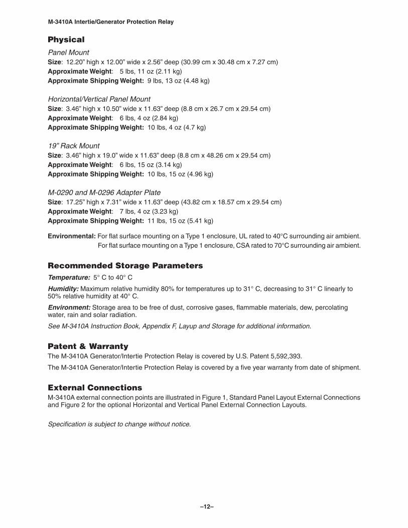
Physical
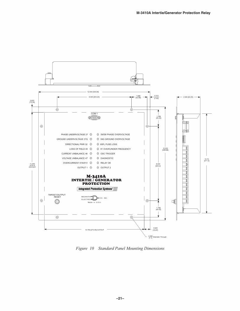
Panel MountSize: 12.20” high x 12.00” wide x 2.56” deep (30.99 cm x 30.48 cm x 7.27 cm)Approximate Weight: 5 lbs, 11 oz (2.11 kg)Approximate Shipping Weight: 9 lbs, 13 oz (4.48 kg)
Horizontal/Vertical Panel MountSize: 3.46” high x 10.50” wide x 11.63” deep (8.8 cm x 26.7 cm x 29.54 cm)Approximate Weight: 6 lbs, 4 oz (2.84 kg)Approximate Shipping Weight: 10 lbs, 4 oz (4.7 kg)
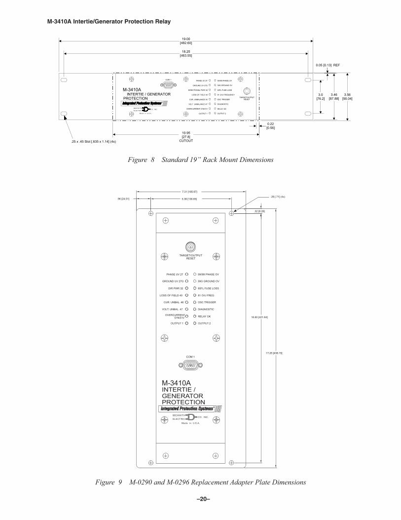
19” Rack MountSize: 3.46” high x 19.0” wide x 11.63” deep (8.8 cm x 48.26 cm x 29.54 cm)Approximate Weight: 6 lbs, 15 oz (3.14 kg)Approximate Shipping Weight: 10 lbs, 15 oz (4.96 kg)
M‑0290 and M‑0296 Adapter PlateSize: 17.25” high x 7.31” wide x 11.63” deep (43.82 cm x 18.57 cm x 29.54 cm)Approximate Weight: 7 lbs, 4 oz (3.23 kg)Approximate Shipping Weight: 11 lbs, 15 oz (5.41 kg)
Environmental: For flat surface mounting on a Type 1 enclosure, UL rated to 40°C surrounding air ambient. For flat surface mounting on a Type 1 enclosure, CSA rated to 70°C surrounding air ambient.
Recommended Storage ParametersTemperature: 5° C to 40° C
Humidity: Maximum relative humidity 80% for temperatures up to 31° C, decreasing to 31° C linearly to 50% relative humidity at 40° C.
Environment: Storage area to be free of dust, corrosive gases, flammable materials, dew, percolating water, rain and solar radiation.
See M‑3410A Instruction Book, Appendix F, Layup and Storage for additional information.
Patent & WarrantyThe M-3410A Generator/Intertie Protection Relay is covered by U.S. Patent 5,592,393.
The M-3410A Generator/Intertie Protection Relay is covered by a five year warranty from date of shipment.
External ConnectionsM-3410A external connection points are illustrated in Figure 1, Standard Panel Layout External Connections and Figure 2 for the optional Horizontal and Vertical Panel External Connection Layouts.
Specification is subject to change without notice.
–13–
M‑3410A Intertie/Generator Protection Relay
�������� �������� ��� �������� ��� � �� �������� �� � � ���
���� � ��� � �� ��
���������
�������
����������
��
��
��
�
���������
��
��
��������
�
�
���������
�
� ����
�
����
��
��
��
���� � � � � �� ��
��
��
��
��
��
��
��
��
��
��
��
�������
����������������������
��
��
��
��
��
��
��
���
��� ��
���������������� ����� �������������������������
���
����
��
������
���
������
�����
�� ��
�������
���
�� ������
������������
��������������������������
��
� ��
� ��
��
��
������������������ ����
��
����������
������������
��
�
�
�
�
�
����
�
�
����
�
�
����
�
�
����
�
��������� ��������� ���������
�
�
�
�
�� �� �������������� �
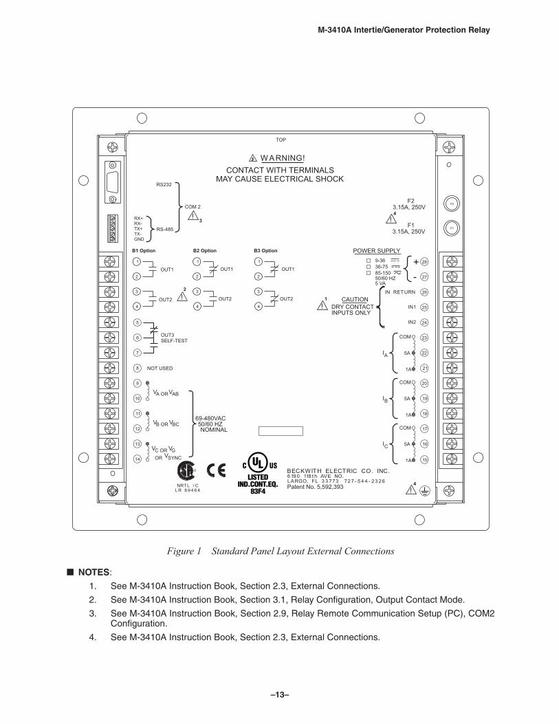
Figure 1 Standard Panel Layout External Connections
NOTES:
1. See M-3410A Instruction Book, Section 2.3, External Connections.
2. See M-3410A Instruction Book, Section 3.1, Relay Configuration, Output Contact Mode.
3. See M-3410A Instruction Book, Section 2.9, Relay Remote Communication Setup (PC), COM2 Configuration.
4. See M-3410A Instruction Book, Section 2.3, External Connections.
–14–
M‑3410A Intertie/Generator Protection Relay
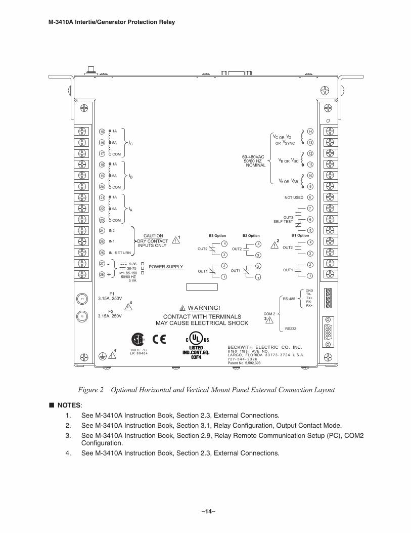
Figure 2 Optional Horizontal and Vertical Mount Panel External Connection Layout
NOTES:
1. See M-3410A Instruction Book, Section 2.3, External Connections.
2. See M-3410A Instruction Book, Section 3.1, Relay Configuration, Output Contact Mode.
3. See M-3410A Instruction Book, Section 2.9, Relay Remote Communication Setup (PC), COM2 Configuration.
4. See M-3410A Instruction Book, Section 2.3, External Connections.
–15–
M‑3410A Intertie/Generator Protection Relay
* VTs are not necessary if generatorrated voltage is < 480 V ac.
Utility System
52Gen
3240
81 59 47 27
M-3410A Generator Protection
CT
*
46 51V
25
*
51N 60FL
Power
F
R
59G R
M-3410A
Communications
User Interface with PC
Waveform Capture(COMTRADE)
Sequence of EventsLogging
Metering
LED Targets
Programmable I/O
OR
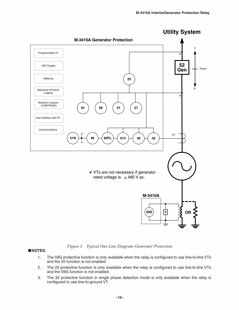
Figure 3 Typical One‑Line Diagram–Generator Protection NOTES:
1. The 59G protective function is only available when the relay is configured to use line-to-line VTs and the 25 function is not enabled.
2. The 25 protective function is only available when the relay is configured to use line-to-line VTs and the 59G function is not enabled.
3. The 32 protective function in single phase detection mode is only available when the relay is configured to use line-to-ground VT.
–16–
M‑3410A Intertie/Generator Protection Relay
* VTs are not necessary if the RatedNominal Interconnection Voltage is< 480 V ac.
59 47 27
CT
M-3410A Intertie Protection
52INT
Utility System
52Gen
81 59I
79
25
*
*
3251V46 60FL51N
Power
F
R
*
27G59G
Programmable I/O
LED Targets
Metering
Sequence of EventsLogging
Waveform Capture(COMTRADE)
User Interface with PC
Communications
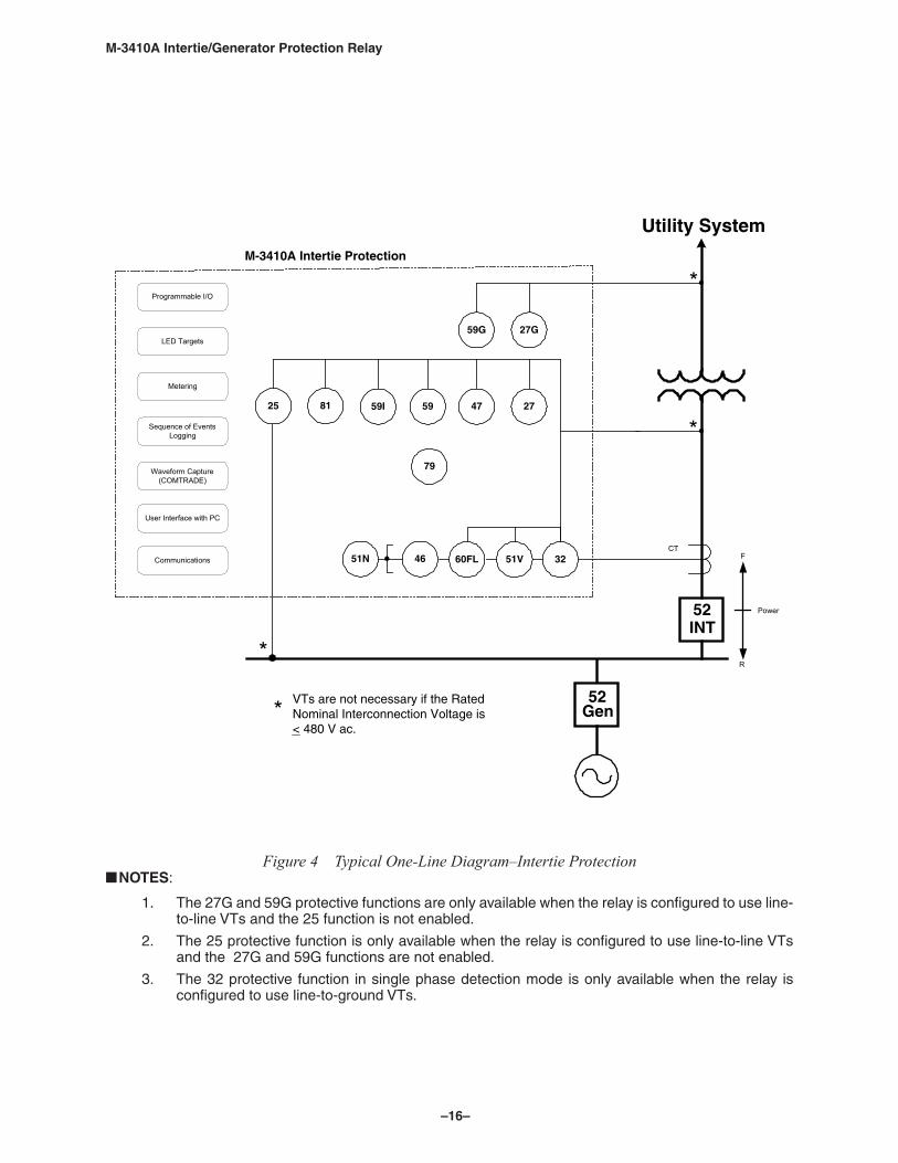
Figure 4 Typical One‑Line Diagram–Intertie Protection NOTES:
1. The 27G and 59G protective functions are only available when the relay is configured to use line-to-line VTs and the 25 function is not enabled.
2. The 25 protective function is only available when the relay is configured to use line-to-line VTs and the 27G and 59G functions are not enabled.
3. The 32 protective function in single phase detection mode is only available when the relay is configured to use line-to-ground VTs.
–17–
M‑3410A Intertie/Generator Protection Relay
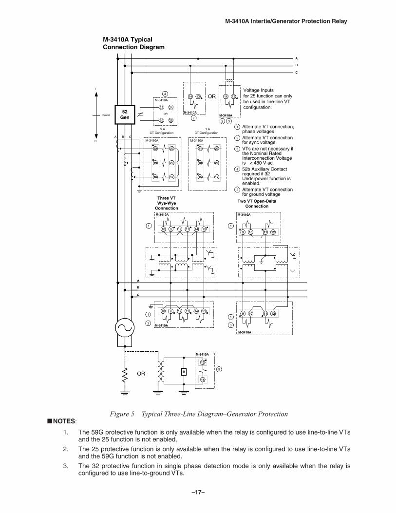
Figure 5 Typical Three‑Line Diagram–Generator Protection NOTES:
1. The 59G protective function is only available when the relay is configured to use line-to-line VTs and the 25 function is not enabled.
2. The 25 protective function is only available when the relay is configured to use line-to-line VTs and the 59G function is not enabled.
3. The 32 protective function in single phase detection mode is only available when the relay is configured to use line-to-ground VTs.
A
B
C
A B C
5 ACT Configuration
1 ACT Configuration
9 11 1310 12 14
M-3410A
1
9 11 1310 12 14
M-3410A
10 129 11
M-3410A
Three VTWye-Wye
Connection
1
Two VT Open-DeltaConnection
1
A
B
C
1314
M-3410AM-3410A
OR
Alternate VT connection,phase voltagesAlternate VT connectionfor sync voltageVTs are not necessary ifthe Nominal RatedInterconnection Voltageis < 480 V ac.52b Auxiliary Contactrequired if 32Underpower function isenabled.Alternate VT connectionfor ground voltage
52Gen
M-3410A TypicalConnection Diagram
1
2
2
2
Voltage Inputsfor 25 function can onlybe used in line-line VTconfiguration.
10 129 11
M-3410A
1
14 13
Power
F
R
R
M-3410A
13
14
16 17
19 20
22 23
M-3410A
15 17
18 20
21 23
M-3410A
3
25
26
24
26
OR
4
M-3410A
3
4
3 3
5
5OR
–18–
M‑3410A Intertie/Generator Protection Relay
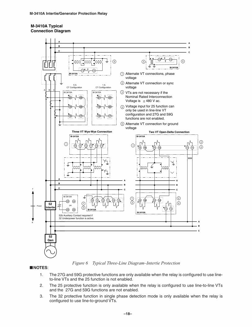
Figure 6 Typical Three‑Line Diagram–Intertie Protection NOTES:
1. The 27G and 59G protective functions are only available when the relay is configured to use line-to-line VTs and the 25 function is not enabled.
2. The 25 protective function is only available when the relay is configured to use line-to-line VTs and the 27G and 59G functions are not enabled.
3. The 32 protective function in single phase detection mode is only available when the relay is configured to use line-to-ground VTs.
A
B
C
52Gen
52Intertie
9 11 1310 12 14
M-3410A3
9 11 1310 12 14
M-3410A
A
B
C
A
B
C
10 129 11
M-3410A
3
10 129 11
M-3410A
A
B
C
13 14
Three VT Wye-Wye Connection Two VT Open-Delta Connection
1
Alternate VT connections, phasevoltage
Alternate VT connection or syncvoltage
VTs are not necessary if theNominal Rated InterconnectionVoltage is < 480 V ac.
Voltage input for 25 function canonly be used in line-line VTconfiguration and 27G and 59Gfunctions are not enabled.
Alternate VT connection for groundvoltage
1
2
M-3410A TypicalConnection Diagram
13 14
Power
F
R
3
4
A
B
C
A
B
C
13 14
13 14
M-3410A
M-3410A
3
A B C
5 ACT Configuration
1 ACT Configuration
16 17
19 20
22 23
M-3410A
15 17
18 20
21 23
M-3410A
25
26
24
26
OR
M-3410A
52b Auxiliary Contact required if32 Underpower function is active.
4
1
1
1
5
5 5
2
4
2
–19–
M‑3410A Intertie/Generator Protection Relay
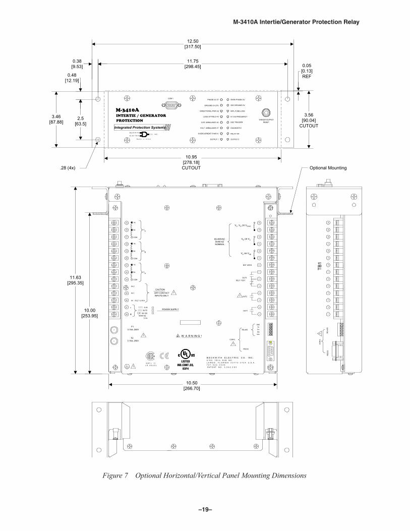
Figure 7 Optional Horizontal/Vertical Panel Mounting Dimensions
F2
F1
NOT USED
SELF-TESTOUT3
OUT2
OUT1
RS-485
RS232
11
1
2
3
4
8
5
6
7
10
9
14
13
12
1A18
3.15A, 250V
i
COM 2
W A R N IN G !3.15A, 250V
i
F2
i
36-75
5 VA
85-15050/60 HZ
9-36POWER SUPPLY
DRY CONTACTINPUTS ONLY
CAUTION i
+
F1
28
-
IN R E T U R N
I N 1
27
26
25
21
I N 2
COM
AI5A
23
22
1A
COM
BI5A
20
19
1A15
COM
I C5A
17
16
i
GNDTX-TX+RX-RX+
N R T L / CL R 8 9 4 6 4
R
69-480VAC50/60 HZNOMINAL
PA T E N T N O . 5 , 5 9 2 , 3 9 3
L A R G O , F L O R I D A 3 3 7 7 3 - 3 7 2 4 U . S . A .
B E C K W IT H E L E C T R IC C O . I N C .
7 2 7 - 5 4 4 - 2 3 2 6
6 19 0 118 t h A V E N O .
11.63[295.35]
10.00[253.95]
Optional Mounting
10.50[266.70]
CO
M 2
RS
232
RS
-485
i
19
23
45
67
810
1112
1314
TB1
M-3410A
COM 1
INTERTIE / GENERATORPROTECTION
B E C K W IT H
E L E C T R ICC O . I N C .
R
CUR. UNBALANCE 46
OVERCURRENT 51N/51V
DIRECTIONAL PWR 32
LOSS OF FIELD 40
VOLT. UNBALANCE 47
GROUND UV 27G
PHASE UV 27
M a d e i n U .S .A . OUTPUT 1
60FL FUSE LOSS
59/59I PHASE OV
59G GROUND OV
81 O/U FREQUENCY
OSC TRIGGER
DIAGNOSTIC
RELAY OK
RESETTARGET/OUTPUT
OUTPUT 2
Integrated Protection Systems
12.50[317.50]
11.75[298.45]
0.38[9.53]
3.46[87.88]
2.5[63.5]
0.48[12.19]
10.95[278.18]CUTOUT
3.56[90.04]
CUTOUT
0.05[0.13]REF
.28 (4x)
LISTEDIND.CONT.EQ.
83F4
VC, VG OR VSYNC
VB OR VC
VA OR VAB
–20–
M‑3410A Intertie/Generator Protection Relay
PROTECTIONINTERTIE / GENERATOR
M-3410A
DIAGNOSTIC
OSC TRIGGER
81 O/U FREQUENCY
59G GROUND OV
59/59I PHASE OV
60FL FUSE LOSS
COM 1
CUR. UNBALANCE 46
PHASE UV 27
GROUND UV 27G
LOSS OF FIELD 40
DIRECTIONAL PWR 32
OUTPUT 1
VOLT. UNBALANCE 47
OVERCURRENT 51N/51V RELAY OK
OUTPUT 2
TARGET/OUTPUTRESET
C O. INC.EL ECT RIC
BECK W IT H
Ma d e in U.S .A .
R
19.00[482.60]
18.25[463.55]
10.95[27.8]
CUTOUT
0.22[0.56]
3.0[76.2]
3.46[87.88]
3.56[90.04]
0.05 [0.13] REF
.25 x .45 Slot [.635 x 1.14] (4x)
Figure 8 Standard 19” Rack Mount Dimensions
��������������
����������
��������������
������ �
�� �� ����� �
��� �������� ��
�
�������������
�������������
�����������
������ ����
������� ��
� �����
��������� ����� ��
�����
��������
��������� ������
��������������
���������������
�����������������
��������
����������
��������
� ������ �
�������������
��������������
���� ���������
������������
�����������
� ��������
�������������
�����
��������������
Figure 9 M‑0290 and M‑0296 Replacement Adapter Plate Dimensions
–21–
M‑3410A Intertie/Generator Protection Relay
�����
������������������������������
��������������������
��������������� ���
��������
������ �����������
�������
��������
��������
�������
��������������������
���������������
��������������
��������������������
���������������������
�� ��������������������
��������������
���������������������
������� ��������������
����������
�������
�������
��� � ����� �
��� ���
�
�������������
��������������
������������
�������������
������
����������������������������������
����������
������������
��������������
���������������
������������
������������
������������
�����
������
������������
�� � ���������
Figure 10 Standard Panel Mounting Dimensions
–22–
M‑3410A Intertie/Generator Protection Relay
CONTACT WITH TERMINALSMAY CAUSE ELECTRICAL SHOCK
BECKWITH ELECTRIC CO. INC.6190 118t h AVE NO.LARGO, FL 33773PATENT NO. 5 ,592,393
VC OR VGOR VSYNC14
50/60 HZ69-480VAC
NOMINAL
VA OR AB
B OR BC
13
12V V
11
10V
SELF-TEST
NOT USED
9
8
7
6 OUT3
W A R N I N G !
MODEL NO.
SERIAL NO.
SERIAL NO.
SOFTWARE NO.
1A
727- 544- 2326
15
COM
5A
1A
COM
5A
1A
COM
5AI C
I B
I A
16
17
18
19
20
21
22
23
81 O/U FREQUENCY
59G GROUND OV
60FL FUSE LOSS
59/59I PHASE OV
TARGET/OUTPUTRESET
RELAY OK
OUTPUT 2
OSC TRIGGER
DIAGNOSTIC
CUR. UNBALANCE 46
LOSS OF FIELD 40
DIRECTIONAL PWR 32
GROUND UV 27G
OVERCURRENT 51N/51V
OUTPUT 1
VOLT. UNBALANCE 47
PHASE UV 27
TOP
5
4
OUT23
2
OUT1
i
RS-485TX-
1
GND
RX+RX-TX+
COM 2
i
BECKWITHELECTRIC .OC .CNI
M-3410A
RS232
3.15A, 250V
F13.15A, 250V
i
F2
IN R ET URN
DRY CONTACTINPUTS ONLY
CAUTION
i
36-7585-15050/60 HZ5 VA
POWER SUPPLY
9-36
IN2
IN1 25
26
- 27
+ 28
F1
F2
R
12.00[304.80]
8.00[203.20
1.69[42.88
12.20[309.88]
8.00[203.20]
1.79[45.42]
1.79[45.42]
0.31[7.92]
0.280 Diameter Through [7.1]
2.98[7.57]
LISTEDIND.CONT.EQ.
83F4
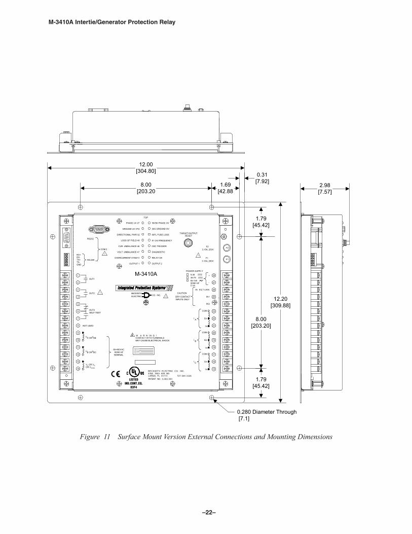
Figure 11 Surface Mount Version External Connections and Mounting Dimensions

–23–
M‑3410A Intertie/Generator Protection Relay
This Page Left Intentionally Blank
BECKWITH ELECTRIC CO., INC.6190 - 118th Avenue North • Largo, Florida 33773-3724 U.S.A.
PHONE (727) 544-2326 • FAX (727) [email protected]
www.beckwithelectric.comISO 9001:2008
800-3410A-SP-04MC3 10/16© 2001 Beckwith Electric Co. All Rights Reserved.Printed in USA


![Distribution Generator Connection Line Protection Digital Multi Protection Relay (K-PAM DG3300) User's Manual 경보전기[주] 2 / 201 안전을 위한 주의사항 사용자의](https://img.pdfslide.tips/doc/110x75/5fa4048f36170935d766d353/distribution-generator-connection-line-protection-digital-multi-protection-relay.jpg)


![사 양 서kyongbo.co.kr/admin/fileDown6.jsp?filename=K-PAM F3300... · Feeder Protection Digital Multi Protection Relay (K-PAM F3300) 사양서 V2.00 2경보전기[주] / 78 사](https://img.pdfslide.tips/doc/110x75/60cf16febbbfa23aa8307ccb/-oe-f3300-feeder-protection-digital-multi-protection-relay-k-pam-f3300.jpg)