Embed Size (px)
Citation preview
Function overview
Description
Siemens SIP · Edition No. 6
11 Generator Protection / 7UM62
11
11/33
Standard version
Scope of basic version plus:
• Inadvertent energization protection
• 100 %-stator earth-fault protectionwith 3rd harmonic
• Impedance protection
Full version
Scope of standard version plus:
• DC voltage protection
• Overcurrent protection during start-ups
• Earth-current differential protection
• Out-of-step protection
Additional version
Available for each version:
• Sensitive rotor earth-fault protection(1-3 Hz method)
• Stator earth-fault protection with20 Hz voltage
• Rate-of-frequency-change protection
• Vector jump supervision
Monitoring function
• Trip circuit supervision
• Fuse failure monitor
• Operational measured values V, I, f, …
• Energy metering values Wp, Wq
• Time metering of operating hours
• Self-supervision of relay
• 8 oscillographic fault records
Communication interfaces
• System interface– IEC 61850 protocol– IEC 60870-5-103 protocol– PROFIBUS-DP– MODBUS RTU– DNP 3.0
Hardware
• Analog inputs
• 8 current transformers
• 4 voltage transformers
• 7/15 binary inputs
• 12/20 output relays
Front design
• User-friendly local operation
• 7/14 LEDs for local alarm
• Function keys
• Graphic display with 7UM623
SIPROTEC 4 7UM62
Multifunction Generator, Motor and Transformer Protection Relay
The SIPROTEC 4 7UM62 protection relayscan do more than just protect. They alsooffer numerous additional functions. Be itearth faults, short-circuits, overloads, over-voltage, overfrequency or underfrequencyasynchronous conditions, protection relaysassure continued operation of power sta-tions. The SIPROTEC 4 7UM62 protectionrelay is a compact unit which has beenspecially developed and designed for theprotection of small, medium-sized andlarge generators. They integrate all thenecessary protection functions and are par-ticularly suited for the protection of:
− Hydro and pumped-storage generators
− Co-generation stations
− Private power stations using regenera-tive energy sources such as wind orbiogases
− Diesel generator stations
− Gas-turbine power stations
− Industrial power stations
− Conventional steam power stations.
The SIPROTEC 4 7UM62 includes allnecessary protection functions for largesynchronous and asynchronous motorsand for transformers.
The integrated programmable logicfunctions (continuous function chartCFC) offer the user high flexibility so that
Fig. 11/34 SIPROTEC 4 7UM62 multifunction protection relay for
generators, motors and transformers
LSP
2171
-afp
en.e
ps
adjustments can easily be made to thevarying power station requirements on thebasis of special system conditions.The flexible communication interfaces areopen for modern communication archi-tectures with the control system.
The following basic functions are availablefor all versions:
Current differential protection forgenerators, motors and transformers,stator earth-fault protection, sensitiveearth-fault protection, stator overload pro-tection, overcurrent- time protection (ei-ther definite time or inverse time),definite-time overcurrent protection withdirectionality, undervoltage and overvolt-age protection, underfrequency andoverfrequency protection, overexcitationand underexcitation protection, externaltrip coupling, forward-power and reverse-power protection, negative-sequence pro-tection, breaker failure protection, rotorearth-faults protection (fn, R-measuring),motor starting time supervision and restartinhibit for motors.
The 7UM6 protection relays of theSIPROTEC 4 family are compact multi-function units which have been developedfor small to medium-sized power genera-tion plants. They incorporate all the neces-sary protective functions and are especiallysuitable for the protection of:
– Hydro and pumped-storage generators– Co-generation stations– Private power stations using regenera-
tive energy sources such as wind orbiogases
– Power generation with dieselgenerators
– Gas turbine power stations– Industrial power stations– Conventional steam power stations.
They can also be employed for protectionof motors and transformers.
The numerous other additional functionsassist the user in ensuring cost-effectivesystem management and reliable powersupply. Measured values display currentoperating conditions. Stored status indica-tions and fault recording provide assistancein fault diagnosis not only in the event of adisturbance in generator operation.
Combination of the units makes it possibleto implement effective redundancy con-cepts.
Protection functions
Numerous protection functions are neces-sary for reliable protection of electrical ma-chines. Their extent and combination aredetermined by a variety of factors, such asmachine size, mode of operation, plantconfiguration, availability requirements,experience and design philosophy.
This results in multifunctionality, which isimplemented in outstanding fashion bynumerical technology.
In order to satisfy differing requirements,the combination of functions is scalable(see Table 11/3). Selection is facilitated bydivision into five groups.
Generator Basic
One application concentrates on small andmedium generators for which differentialprotection is required. The function mix isalso suitable as backup protection. Protec-tion of synchronous motors is a further ap-plication.
Generator Standard
In the case of medium-size generators(10 to 100 MVA) in a unit connection, thisscope of functions offers all necessaryprotection functions. Besides inadvertentenergization protection, it also includespowerful backup protection for the trans-former or the power system. The scope ofprotection is also suitable for units in thesecond protection group.
Generator Full
Here, all protection functions are availableand the main application focuses on largeblock units (more than 100 MVA). Thefunction mix includes all necessary protec-tion functions for the generator as well asbackup protection for the block trans-former including the power system. Addi-tional functions such as protection duringstart-up for generators with starting con-verters are also included.
The scope of functions can be used for thesecond protection group, and functionsthat are not used, can be masked out.
Asynchronous motor
Besides differential protection, this func-tion package includes all protection func-tions needed to protect large asynchronousmotors (more than 1 MVA). Stator andbearing temperatures are measured by aseparate thermo-box and are transmittedserially to the protection unit for evalua-tion.
Transformer
This scope of functions not only includesdifferential and overcurrent protection,but also a number of protection functionsthat permit monitoring of voltage and fre-quency stress, for instance. The reverse-power protection can be used for energyrecovery monitoring of parallel-connectedtransformers.
Siemens SIP · Edition No. 6
11 Generator Protection / 7UM62
11
11/34
Application Construction
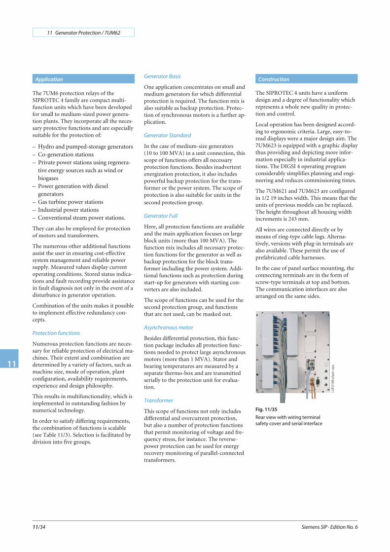
Fig. 11/35
Rear view with wiring terminal
safety cover and serial interface
The SIPROTEC 4 units have a uniformdesign and a degree of functionality whichrepresents a whole new quality in protec-tion and control.
Local operation has been designed accord-ing to ergonomic criteria. Large, easy-to-read displays were a major design aim. The7UM623 is equipped with a graphic displaythus providing and depicting more infor-mation especially in industrial applica-tions. The DIGSI 4 operating programconsiderably simplifies planning and engi-neering and reduces commissioning times.
The 7UM621 and 7UM623 are configuredin 1/2 19 inches width. This means that theunits of previous models can be replaced.The height throughout all housing widthincrements is 243 mm.
All wires are connected directly or bymeans of ring-type cable lugs. Alterna-tively, versions with plug-in terminals arealso available. These permit the use ofprefabricated cable harnesses.
In the case of panel surface mounting, theconnecting terminals are in the form ofscrew-type terminals at top and bottom.The communication interfaces are alsoarranged on the same sides.
LSP
2166
-afp
en.e
ps
Siemens SIP · Edition No. 6
11 Generator Protection / 7UM62
11
11/35
Protection functions
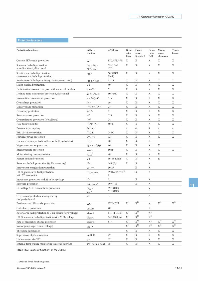
Protection functions Abbre-viation
ANSI No. Gene-ratorBasic
Gene-ratorStandard
Gene-ratorFull
MotorAsyn-chronous
Trans-former
Current differential protection Δ I 87G/87T/87M X X X X X
Stator earth-fault protectionnon-directional, directional
V0>, 3I0>\(V0, 3I0)
59N, 64G67G
X X X X X
Sensitive earth-fault protection(also rotor earth-fault protection)
IEE> 50/51GN(64R)
X X X X X
Sensitive earth-fault prot. B (e.g. shaft current prot.) IEE-B> IEE-B< 51GN X X X X X
Stator overload protection I2t 49 X X X X X
Definite-time overcurrent prot. with undervolt. seal-in I> +V< 51 X X X X X
Definite-time overcurrent protection, directional I>>, Direc. 50/51/67 X X X X X
Inverse-time overcurrent protection t = f (I)+V< 51V X X X X X
Overvoltage protection V> 59 X X X X X
Undervoltage protection V<, t = f (V) 27 X X X X X
Frequency protection f<, f> 81 X X X X X
Reverse-power protection -P 32R X X X X X
Overexcitation protection (Volt/Hertz) V/f 24 X X X X X
Fuse failure monitor V2/V1, I2/I1 60FL X X X X X
External trip coupling Incoup. 4 4 4 4 4
Trip circuit supervision T.C.S. 74TC X X X X X
Forward-power protection P>, P< 32F X X X X X
Underexcitation protection (loss-of-field protection) 1/xd 40 X X X
Negative-sequence protection I2>, t = f (I2) 46 X X X X
Breaker failure protection Imin> 50BF X X X X X
Motor starting time supervision Istart2t 48 X X X X
Restart inhibit for motors I2t 66, 49 Rotor X X X X
Rotor earth-fault protection (fn, R-measuring) R< 64R (fn) X X X
Inadvertent energization protection I>, V< 50/27 X X
100 % stator earth-fault protectionwith 3rd harmonics
V0(3rd harm.) 59TN, 27TN 3rd
hX X
Impedance protection with (I>+V<) pickup Z< 21 X X
Interturn protection UInterturn> 59N(IT) X X
DC voltage / DC current time protection Vdc >Idc >
59N (DC)51N (DC)
X
Overcurrent protection during startup(for gas turbines)
I> 51 X
Earth-current differential protection ΔIe 87GN/TN X1) X1)X X1) X1)
Out-of-step protection ΔZ/Δt 78 X
Rotor earth-fault protection (1-3 Hz square wave voltage) RREF< 64R (1–3 Hz) X1) X1) X1)
100 % stator earth-fault protection with 20 Hz voltage RSEF< 64G (100 %) X1) X1) X1)
Rate-of-frequency-change protection df/dt > 81R X1) X1) X1) X1) X1)
Vector jump supervision (voltage) Δ > X1) X1) X1) X1) X1)
Threshold supervision X X X X X
Supervision of phase rotation A, B, C 47 X X X X X
Undercurrent via CFC I < 37 X X X X X
External temperature monitoring via serial interface (Thermo-box) 38 X X X X X
Table 11/3 Scope of functions of the 7UM62
1) Optional for all function groups.

Current differential protection
(ANSI 87G, 87M, 87T)
This function provides undelayed short-cir-cuit protection for generators, motors andtransformers, and is based on the currentdifferential protection principle (Kirchhoff’scurrent law).
The differential and restraint (stabilization)current are calculated on the basis of thephase currents. Optimized digital filters reli-ably attenuate disturbances such as aperio-dic component and harmonics. The highresolution of measured quantities permitsrecording of low differential currents (10 %of IN) and thus a very high sensitivity.
An adjustable restraint characteristic per-mits optimum adaptation to the conditionsof the protected object. Software is used tocorrect the possible mismatch of the currenttransformers and the phase angle rotationthrough the transformer (vector group).Thanks to harmonic analysis of the differen-tial current, inrush (second harmonic) andoverexcitation (fifth harmonic) are reliablydetected, and unwanted operation of thedifferential protection is prevented. Thecurrent of internal short-circuits is reliablymeasured by a fast measuring stage(IDiff>>), which operates with two mutuallycomplementary measuring processes. Anexternal short-circuit with transformer satu-ration is picked up by a saturation detectorwith time and status monitoring. It becomesactive when the differential current (IDiff)moves out of the add-on restraint area.
If a motor is connected, this is detected bymonitoring the restraint current and therestraint characteristic is briefly raised.This prevents false tripping in the event ofunequal current transmission by the cur-rent transformers.
Figure 11/36 shows the restraintcharacteristic and various areas.
Earth-current differential protection
(ANSI 87GN, 87TN)
The earth-current differential protectionpermits high sensitivity to single-pole faults.The zero currents are compared. On the onehand, the zero-sequence current is calcu-lated on the basis of the phase currents andon the other hand, the earth current is mea-sured directly at the star-point currenttransformer.
The differential and restraint quantity isgenerated and fitted into the restraintcharacteristic (see Fig. 11/37).
DC components in particular are sup-pressed by means of specially dimensionedfilters. A number of monitoring proc-esses avoid unwanted operation in the eventof external short-circuits. In the case of asensitive setting, multiple measurementensures the necessary reliability.
However, attention must be drawn to thefact that the sensitivity limits are determinedby the current transformers.
The protection function is only used ongenerators when the neutral point isearthed with a low impedance. In the caseof transformers, it is connected on the neu-tral side. Low impedance or solid earthingis also required.
Siemens SIP · Edition No. 6
11 Generator Protection / 7UM62
11
11/36
Protection functions
Fig. 11/36 Restraint characteristic of current differential protection
Fig. 11/37 Restraint characteristic of earth-current differential protection
Definite-time overcurrent protection
I>, I>> (ANSI 50, 51, 67)
This protection function comprises theshort-circuit protection for the generatorand also the backup protection for up-stream devices such as transformers orpower system protection.
An undervoltage stage at I> maintains thepickup when, during the fault, the currentdrops below the threshold. In the event of avoltage drop on the generator terminals, thestatic excitation system can no longer besufficiently supplied. This is one reason forthe decrease of the short-circuit current.
The I>> stage can be implemented ashigh-set instantaneous trip stage. With theintegrated directional function it can beused as backup protection on the trans-former high-voltage side. With the infor-mation of the directional element,impedance protection can be controlledvia the CFC.
Inverse-time overcurrent protection
(ANSI 51V)
This function also comprises short-circuitand backup protection and is used forpower system protection with current-dependent protection devices.
IEC and ANSI characteristics can beselected (Table 11/4).
The current function can be controlled byevaluating the generator terminal voltage.
The “controlled” version releases thesensitive set current stage.
With the “restraint” version, the pickupvalue of the current is lowered linearly withdecreasing voltage.
The fuse failure monitor preventsunwanted operation.
Stator overload protection (ANSI 49)
The task of the overload protection is toprotect the stator windings of generatorsand motors from high, continuous over-load currents. All load variations are evalu-ated by a mathematical model. Thethermal effect of the r.m.s. current valueforms the basis of the calculation.This conforms to IEC 60255-8.In dependency of the current, the coolingtime constant is automatically extended. Ifthe ambient temperature or the tempera-ture of the coolant are injected via a trans-ducer (TD2) or PROFIBUS-DP, the modelautomatically adapts to the ambient condi-tions; otherwise a constant ambient tem-perature is assumed.
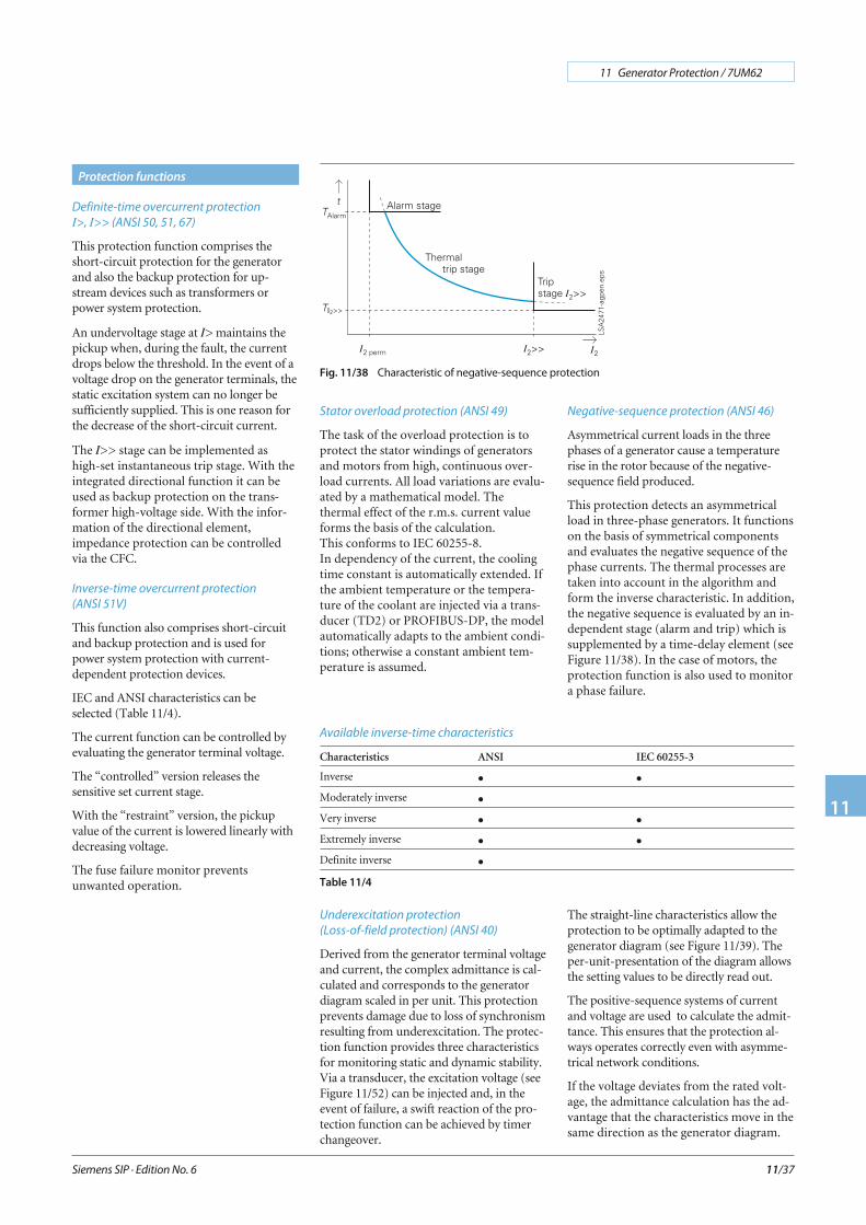
Negative-sequence protection (ANSI 46)
Asymmetrical current loads in the threephases of a generator cause a temperaturerise in the rotor because of the negative-sequence field produced.
This protection detects an asymmetricalload in three-phase generators. It functionson the basis of symmetrical componentsand evaluates the negative sequence of thephase currents. The thermal processes aretaken into account in the algorithm andform the inverse characteristic. In addition,the negative sequence is evaluated by an in-dependent stage (alarm and trip) which issupplemented by a time-delay element (seeFigure 11/38). In the case of motors, theprotection function is also used to monitora phase failure.
Siemens SIP · Edition No. 6
11 Generator Protection / 7UM62
11
11/37
Protection functions
Fig. 11/38 Characteristic of negative-sequence protection
Available inverse-time characteristics
Characteristics ANSI IEC 60255-3
Inverse • •Moderately inverse •Very inverse • •Extremely inverse • •Definite inverse •
Table 11/4
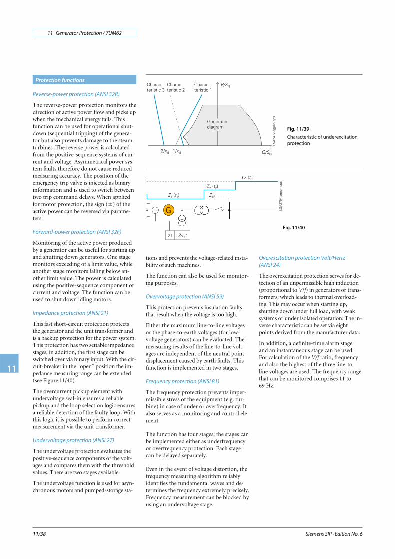
Underexcitation protection
(Loss-of-field protection) (ANSI 40)
Derived from the generator terminal voltageand current, the complex admittance is cal-culated and corresponds to the generatordiagram scaled in per unit. This protectionprevents damage due to loss of synchronismresulting from underexcitation. The protec-tion function provides three characteristicsfor monitoring static and dynamic stability.Via a transducer, the excitation voltage (seeFigure 11/52) can be injected and, in theevent of failure, a swift reaction of the pro-tection function can be achieved by timerchangeover.
The straight-line characteristics allow theprotection to be optimally adapted to thegenerator diagram (see Figure 11/39). Theper-unit-presentation of the diagram allowsthe setting values to be directly read out.
The positive-sequence systems of currentand voltage are used to calculate the admit-tance. This ensures that the protection al-ways operates correctly even with asymme-trical network conditions.
If the voltage deviates from the rated volt-age, the admittance calculation has the ad-vantage that the characteristics move in thesame direction as the generator diagram.
Reverse-power protection (ANSI 32R)
The reverse-power protection monitors thedirection of active power flow and picks upwhen the mechanical energy fails. Thisfunction can be used for operational shut-down (sequential tripping) of the genera-tor but also prevents damage to the steamturbines. The reverse power is calculatedfrom the positive-sequence systems of cur-rent and voltage. Asymmetrical power sys-tem faults therefore do not cause reducedmeasuring accuracy. The position of theemergency trip valve is injected as binaryinformation and is used to switch betweentwo trip command delays. When appliedfor motor protection, the sign (±) of theactive power can be reversed via parame-ters.
Forward-power protection (ANSI 32F)
Monitoring of the active power producedby a generator can be useful for starting upand shutting down generators. One stagemonitors exceeding of a limit value, whileanother stage monitors falling below an-other limit value. The power is calculatedusing the positive-sequence component ofcurrent and voltage. The function can beused to shut down idling motors.
Impedance protection (ANSI 21)
This fast short-circuit protection protectsthe generator and the unit transformer andis a backup protection for the power system.This protection has two settable impedancestages; in addition, the first stage can beswitched over via binary input. With the cir-cuit-breaker in the “open” position the im-pedance measuring range can be extended(see Figure 11/40).
The overcurrent pickup element withundervoltage seal-in ensures a reliablepickup and the loop selection logic ensuresa reliable detection of the faulty loop. Withthis logic it is possible to perform correctmeasurement via the unit transformer.
Undervoltage protection (ANSI 27)
The undervoltage protection evaluates thepositive-sequence components of the volt-ages and compares them with the thresholdvalues. There are two stages available.
The undervoltage function is used for asyn-chronous motors and pumped-storage sta-
tions and prevents the voltage-related insta-bility of such machines.
The function can also be used for monitor-ing purposes.
Overvoltage protection (ANSI 59)
This protection prevents insulation faultsthat result when the voltage is too high.
Either the maximum line-to-line voltagesor the phase-to-earth voltages (for low-voltage generators) can be evaluated. Themeasuring results of the line-to-line volt-ages are independent of the neutral pointdisplacement caused by earth faults. Thisfunction is implemented in two stages.
Frequency protection (ANSI 81)
The frequency protection prevents imper-missible stress of the equipment (e.g. tur-bine) in case of under or overfrequency. Italso serves as a monitoring and control ele-ment.
The function has four stages; the stages canbe implemented either as underfrequencyor overfrequency protection. Each stagecan be delayed separately.
Even in the event of voltage distortion, thefrequency measuring algorithm reliablyidentifies the fundamental waves and de-termines the frequency extremely precisely.Frequency measurement can be blocked byusing an undervoltage stage.
Overexcitation protection Volt/Hertz
(ANSI 24)
The overexcitation protection serves for de-tection of an unpermissible high induction(proportional to V/f) in generators or trans-formers, which leads to thermal overload-ing. This may occur when starting up,shutting down under full load, with weaksystems or under isolated operation. The in-verse characteristic can be set via eightpoints derived from the manufacturer data.
In addition, a definite-time alarm stageand an instantaneous stage can be used.For calculation of the V/f ratio, frequencyand also the highest of the three line-to-line voltages are used. The frequency rangethat can be monitored comprises 11 to69 Hz.
Siemens SIP · Edition No. 6
11 Generator Protection / 7UM62
11
11/38
Protection functions
Fig. 11/39
Characteristic of underexcitation
protection
Fig. 11/40
90 % stator earth-fault protection, non-di-
rectional, directional (ANSI 59N, 64G, 67G)
Earth faults manifest themselves in genera-tors that are operated in isolation by theoccurence of a displacement voltage. In caseof unit connections, the displacement volt-age is an adequate, selective criterion forprotection.
For the selective earth-fault detection, thedirection of the flowing earth current has tobe evaluated too, if there is a direct connec-tion between generator and busbar.
The protection relay measures the displace-ment voltage at a VT located at the trans-former star point or at the broken deltawinding of a VT As an option, it is also pos-sible to calculate the zero-sequence voltagefrom the phase-to-earth voltages.
Depending on the load resistor selection, 90to 95 % of the stator winding of a generatorcan be protected.
A sensitive current input is available forearth-current measurement. This inputshould be connected to a core-balance cur-rent transformer. The fault direction is de-duced from the displacement voltage andearth current. The directional characteristic(straight line) can be easily adapted to thesystem conditions. Effective protection fordirect connection of a generator to a busbarcan therefore be established. During start-up, it is possible to switch over from the di-rectional to the displacement voltage mea-surement via an externally injected signal.
Depending on the protection setting,various earth-fault protection concepts canbe implemented with this function(see Figures 11/51 to 11/54).
Sensitive earth-fault protection
(ANSI 50/51GN, 64R)
The sensitive earth-current input can alsobe used as separate earth-fault protection. Itis of two-stage form. Secondary earth cur-rents of 2 mA or higher can be reliably han-dled.
Alternatively, this input is also suitable asrotor earth-fault protection. A voltage withrated frequency (50 or 60 Hz) is connectedin the rotor circuit via the interface unit7XR61. If a higher earth current is flowing,a rotor earth fault has occurred. Measuringcircuit monitoring is provided for this ap-plication (see Figure 11/56).
100 % stator earth-fault protection with 3rd
harmonic (ANSI 59TN, 27TN (3rdH.))
Owing to the creative design, the generatorproduces a 3rd harmonic that forms a zerophase-sequence system. It is verifiable by theprotection on a broken delta winding or onthe neutral transformer. The magnitude ofthe voltage amplitude depends on the gen-erator and its operation.
In the event of an earth fault in the vicinityof the neutral point, there is a change in theamplitude of the 3rd harmonic voltage(dropping in the neutral point and rising atthe terminals).
Depending on the connection the protec-tion must be set either as undervoltage orovervoltage protection. It can also be de-layed. So as to avoid overfunction, the activepower and the positive-sequence voltage actas enabling criteria.
The picked-up threshold of the voltage stageis restrained by the active power. This in-creases sensitivity at low load.
The final protection setting can be madeonly by way of a primary test with the gen-erator.
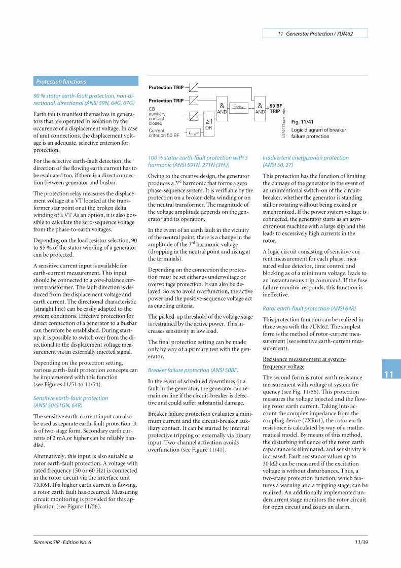
Breaker failure protection (ANSI 50BF)
In the event of scheduled downtimes or afault in the generator, the generator can re-main on line if the circuit-breaker is defec-tive and could suffer substantial damage.
Breaker failure protection evaluates a mini-mum current and the circuit-breaker aux-iliary contact. It can be started by internalprotective tripping or externally via binaryinput. Two-channel activation avoidsoverfunction (see Figure 11/41).
Inadvertent energization protection
(ANSI 50, 27)
This protection has the function of limitingthe damage of the generator in the event ofan unintentional switch-on of the circuit-breaker, whether the generator is standingstill or rotating without being excited orsynchronized. If the power system voltage isconnected, the generator starts as an asyn-chronous machine with a large slip and thisleads to excessively high currents in therotor.
A logic circuit consisting of sensitive cur-rent measurement for each phase, mea-sured value detector, time control andblocking as of a minimum voltage, leads toan instantaneous trip command. If the fusefailure monitor responds, this function isineffective.
Rotor earth-fault protection (ANSI 64R)
This protection function can be realized inthree ways with the 7UM62. The simplestform is the method of rotor-current mea-surement (see sensitive earth-current mea-surement).
Resistance measurement at system-frequency voltage
The second form is rotor earth resistancemeasurement with voltage at system fre-quency (see Fig. 11/56). This protectionmeasures the voltage injected and the flow-ing rotor earth current. Taking into ac-count the complex impedance from thecoupling device (7XR61), the rotor earthresistance is calculated by way of a mathe-matical model. By means of this method,the disturbing influence of the rotor earthcapacitance is eliminated, and sensitivity isincreased. Fault resistance values up to30 kΩ can be measured if the excitationvoltage is without disturbances. Thus, atwo-stage protection function, which fea-tures a warning and a tripping stage, can berealized. An additionally implemented un-dercurrent stage monitors the rotor circuitfor open circuit and issues an alarm.
Siemens SIP · Edition No. 6
11 Generator Protection / 7UM62
11
11/39
Protection functions
Fig. 11/41
Logic diagram of breaker
failure protection
Resistance measurement with a square wavevoltage of 1 to 3 Hz
A higher sensitivity is required for largergenerators. On the one hand, the disturbinginfluence of the rotor earth capacitancemust be eliminated more effectively and, onthe other hand, the noise ratio with respectto the harmonics (e.g. sixth harmonic) ofthe excitation equipment must be increased.Injecting a low-frequency square wave volt-age into the rotor circuit has proven itselfexcellently here (see Figure 11/57).
The square wave voltage injected throughthe controlling unit 7XT71 leads to perma-nent recharging of the rotor earth capaci-tance. By way of a shunt in the controllingunit, the flowing earth current is measuredand is injected into the protection unit(measurement input). In the absence of afault (RE ≈ ∞), the rotor earth current aftercharging of the earth capacitance is close tozero. In the event of an earth fault, thefault resistance including the coupling re-sistance (7XR6004), and also the injectingvoltage, defines the stationary current. Thecurrent square wave voltage and the fre-quency are measured via the second input(control input). Fault resistance values upto 80 kΩ can be measured by this measure-ment principle. The rotor earth circuit ismonitored for discontinuities by evalua-tion of the current during the polarity re-versals.
100% stator earth-fault protection with
20 Hz injection (ANSI 64 G (100%))
Injecting a 20 Hz voltage to detect earthfaults even at the neutral point of generatorshas proven to be a safe and reliable method.Contrary to the third harmonic criterion(see page 11/8), it is independent of thegenerator’s characteristics and the modeof operation. Measurement is also possibleduring system standstill (Fig. 11/55).
This protection function is designed so as todetect both earth faults in the entire genera-tor (genuine 100 %) and all electrically con-nected system components.
The protection unit measures the injected20 Hz voltage and the flowing 20 Hz cur-rent. The disturbing variables, for examplestator earth capacitance, are eliminated byway of a mathematical model, and theohmic fault resistance is determined.
On the one hand, this ensures high sensitiv-ity and, on the other hand, it permits use ofgenerators with large earth capacitance val-ues, e.g. large hydroelectric generators.
Phase-angle errors through the earthing orneutral transformer are measured duringcommissioning and are corrected in the al-gorithm.
The protection function has a warning andtripping stage. The measurement circuit isalso monitored and failure of the 20 Hzgenerator is measured.
Independent of earth resistance calcula-tion, the protection function additionallyevaluates the amount of the r.m.s. currentvalue.
Starting time supervision (motor protection
only) (ANSI 48)
Starting time supervision protects the motoragainst long unwanted start-ups, whichmight occur as a result of excessive loadtorque or excessive voltage drops within themotor, or if the rotor is locked.
The tripping time is dependent on thesquare of the start-up current and the setstart-up time (Inverse Characteristic). Itadapts itself to the start-up with reducedvoltage. The tripping time is determined inaccordance with the following formula:
t tTripstart
rmsstart max=
⎛⎝⎜
⎞⎠⎟ ⋅I
I
2
tTrip Tripping time
Istart Permissible start-up current
tstart max Permissible start-up time
Irms Measured r.m.s. current value
Calculation is not started until the currentIrms is higher than an adjustable responsevalue (e.g. 2 IN, MOTOR).
If the permissible locked-rotor time is lessthan the permissible start-up time (motorswith a thermally critical rotor), a binarysignal is set to detect a locked rotor bymeans of a tachometer generator. This bi-nary signal releases the set locked-rotortime, and tripping occurs after it haselapsed.
DC voltage time protection/DC current time
protection (ANSI 59N (DC) 51N (DC))
Hydroelectric generators or gas turbines arestarted by way of frequency starting con-verters. An earth fault in the intermediatecircuit of the frequency starting convertercauses DC voltage displacement and thus adirect current. As the neutral or earthingtransformers have a lower ohmic resistancethan the voltage transformers, the largestpart of the direct current flows throughthem, thus posing a risk of destruction fromthermal overloading.
As shown in Fig. 11/55, the direct currentis measured by means of a shunt trans-former (measuring transducer) connecteddirectly to the shunt. Voltages or currentsare fed to the 7UM62 depending on theversion of the measuring transducer. Themeasurement algorithm filters out the DCcomponent and takes the threshold valuedecision. The protection function is activeas from 0 Hz.
If the measuring transducer transmits avoltage for protection, the connection mustbe interference-free and must be kept short.
The implemented function can also beused for special applications. Thus, ther.m.s. value can be evaluated for the quan-tity applied at the input over a wide fre-quency range.
Overcurrent protection during start-up
(ANSI 51)
Gas turbines are started by means of fre-quency starting converters. Overcurrentprotection during start-up measures short-circuits in the lower frequency level (asfrom about 5 Hz) and is designed as inde-pendent overcurrent-time protection. Thepickup value is set below the rated current.The function is only active during start-up.If frequencies are higher than 10 Hz, sam-pling frequency correction takes effect andthe further short-circuit protection func-tions are active.
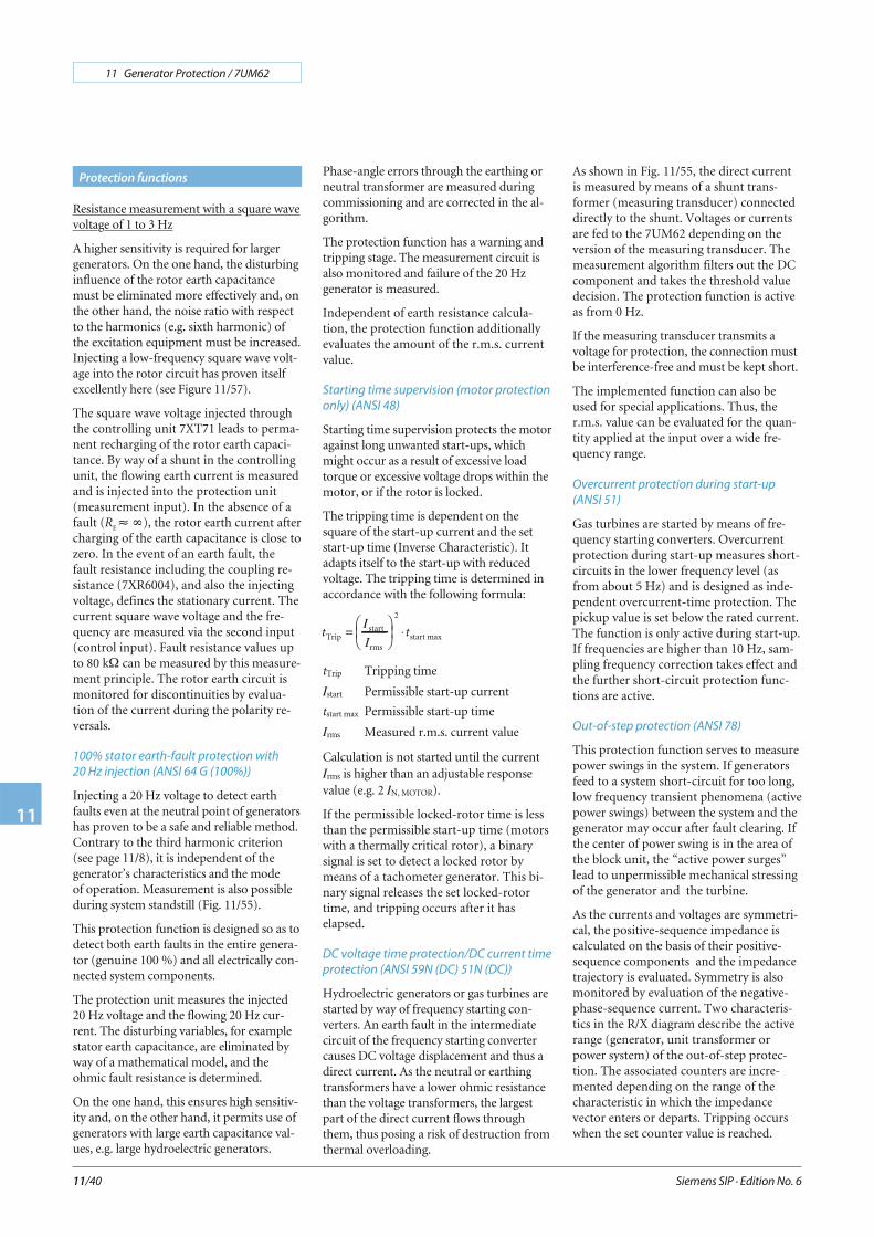
Out-of-step protection (ANSI 78)
This protection function serves to measurepower swings in the system. If generatorsfeed to a system short-circuit for too long,low frequency transient phenomena (activepower swings) between the system and thegenerator may occur after fault clearing. Ifthe center of power swing is in the area ofthe block unit, the “active power surges”lead to unpermissible mechanical stressingof the generator and the turbine.
As the currents and voltages are symmetri-cal, the positive-sequence impedance iscalculated on the basis of their positive-sequence components and the impedancetrajectory is evaluated. Symmetry is alsomonitored by evaluation of the negative-phase-sequence current. Two characteris-tics in the R/X diagram describe the activerange (generator, unit transformer orpower system) of the out-of-step protec-tion. The associated counters are incre-mented depending on the range of thecharacteristic in which the impedancevector enters or departs. Tripping occurswhen the set counter value is reached.
Siemens SIP · Edition No. 6
11 Generator Protection / 7UM62
11
11/40
Protection functions
The counters are automatically reset ifpower swing no longer occurs after a settime. By means of an adjustable pulse, ev-ery power swing can be signaled. Expan-sion of the characteristic in the R directiondefines the power swing angle that can bemeasured. An angle of 120 ° is practicable.The characteristic can be tilted over an ad-justable angle to adapt to the conditionsprevailing when several parallel generatorsfeed into the system.
Inverse undervoltage protection (ANSI 27)
Motors tend to fall out of step when theirtorque is less than the breakdown torque.This, in turn, depends on the voltage. Onthe one hand, it is desirable to keep the mo-tors connected to the system for as long aspossible while, on the other hand, thetorque should not fall below the breakdownlevel. This protection task is realized by in-verse undervoltage protection. The inversecharacteristic is started if the voltage is lessthan the pickup threshold Vp<. The trippingtime is inversely proportional to the voltagedip (see equation). The protection functionuses the positive-sequence voltage, for theprotection decision.
tV
V
TTRIP
p
M=−
⋅I
I
tTRIP Tripping time
V Voltage
Vp Pickup value
TM Time multiplier
System disconnection
Take the case of in-plant generators feed-ing directly into a system. The incomingline is generally the legal entity boundarybetween the system owner and the in-plantgenerator. If the incoming line fails as theresult of auto-reclosure, for instance, avoltage or frequency deviation may occurdepending on the power balance at thefeeding generator. Asynchronous condi-tions may arise in the event of connection,which may lead to damage on the genera-tor or the gearing between the generatorand the turbine. Besides the classic criteriasuch as voltage and frequency, the follow-ing two criteria are also applied: vectorjump, rate-of-frequency-change protec-tion.
Rate-of-frequency-change protection
(ANSI 81)
The frequency difference is determined onthe basis of the calculated frequency over atime interval. It corresponds to the mo-mentary rate-of-frequency change. Thefunction is designed so that it reacts toboth positive and negative rate-of-frequency changes. Exceeding of the per-missible rate-of-frequency change is moni-tored constantly. Release of the relevantdirection depends on whether the actualfrequency is above or below the rated fre-quency. In total, four stages are available,and can be used optionally.
Vector jump
Monitoring the phase angle in the voltageis a criterion for identifying an interruptedinfeed. If the incoming line should fail, theabrupt current discontinuity leads to aphase angle jump in the voltage. This ismeasured by means of a delta process. Thecommand for opening the generator orcoupler circuit-breaker is issued if the setthreshold is exceeded.
Restart inhibit for motors
(ANSI 66, 49Rotor)
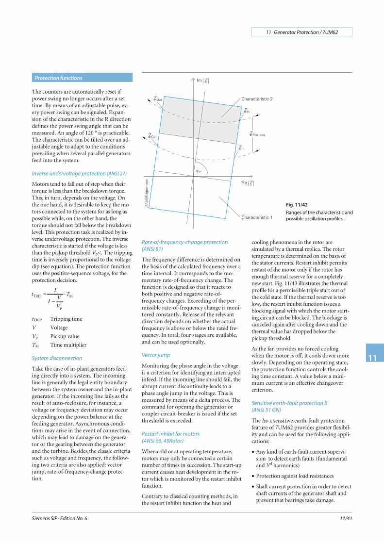
When cold or at operating temperature,motors may only be connected a certainnumber of times in succession. The start-upcurrent causes heat development in the ro-tor which is monitored by the restart inhibitfunction.
Contrary to classical counting methods, inthe restart inhibit function the heat and
cooling phenomena in the rotor aresimulated by a thermal replica. The rotortemperature is determined on the basis ofthe stator currents. Restart inhibit permitsrestart of the motor only if the rotor hasenough thermal reserve for a completelynew start. Fig. 11/43 illustrates the thermalprofile for a permissible triple start out ofthe cold state. If the thermal reserve is toolow, the restart inhibit function issues ablocking signal with which the motor start-ing circuit can be blocked. The blockage iscanceled again after cooling down and thethermal value has dropped below thepickup threshold.
As the fan provides no forced coolingwhen the motor is off, it cools down moreslowly. Depending on the operating state,the protection function controls the cool-ing time constant. A value below a mini-mum current is an effective changeovercriterion.
Sensitive earth-fault protection B
(ANSI 51 GN)
The IEE-B sensitive earth-fault protectionfeature of 7UM62 provides greater flexibil-ity and can be used for the following appli-cations:
• Any kind of earth-fault current supervi-sion to detect earth faults (fundamentaland 3rd harmonics)
• Protection against load resistances
• Shaft current protection in order to detectshaft currents of the generator shaft andprevent that bearings take damage.
Siemens SIP · Edition No. 6
11 Generator Protection / 7UM62
11
11/41
Protection functions
Fig. 11/42
Ranges of the characteristic and
possible oscillation profiles.
The sensitive earth-current protection IEE-B
uses either the hardware input IEE1 or IEE2.These inputs are designed in a way that al-lows them to cut off currents greater than1.6 A (thermal limit, see technical data).This has to be considered for the applica-tions or for the selection of the currenttransformers.
The shaft current protection function is ofparticular interest in conjunction with hy-dro-electric generators. Due to their con-struction, the hydroelectric generatorshave relatively long shafts. A number offactors such as friction, magnetic fields ofthe generators and others can build up avoltage across the shaft which then acts asvoltage source (electro-motive force-emf).This inducted voltage of approx. 10 to 30 Vis dependent on the load, the system andthe machine.
If the oil film covering a bearing is toothin, breakdown can occur. Due to the lowresistance (shaft, bearing and earthing),high currents may flow that destroy thebearing. Past experience has shown thatcurrents greater than 1 A are critical for thebearings. As different bearings can be af-fected, the current entering the shaft is de-tected by means of a special transformer(folding transformer).
Interturn protection (ANSI 59N (IT))
The interturn fault protection detects faultsbetween turns within a generator winding(phase). This situation may involve rela-tively high circulating currents that flow inthe short-circuited turns and damage thewinding and the stator. The protectionfunction is characterized by a high sensitiv-ity.
The displacement voltage is measured atthe open delta winding by means of 3two-phase isolated voltage transformers.So as to be insensitive towards earth faults,the isolated voltage transformer star pointhas to be connected to the generator starpoint by means of a high-voltage cable.The voltage transformer star point mustnot be earthed since this implies that thegenerator star point, too, would be earthedwith the consequence that each fault wouldlead to a single-pole earth fault.
In the event of an interturn fault, the volt-age in the affected phase will be reducedcausing a displacement voltage that is de-tected at the broken delta winding. Thesensitivity is limited rather by the windingasymmetries than by the protection unit.
An FIR filter determines the fundamentalcomponent of the voltage based an thescanned displacement voltage. Selecting anappropriate window function has the effectthat the sensitivity towards higher-fre-quency oscillations is improved and thedisturbing influence of the third harmonicis eliminated while achieving the requiredmeasurement sensitivity.
External trip coupling
For recording and processing of externaltrip information, there are 4 binary inputs.They are provided for information fromthe Buchholz relay or generator-specificcommands and act like a protection func-tion. Each input initiates a fault event andcan be individually delayed by a timer.
Trip circuit supervision (ANSI 74TC)
One or two binary inputs can be used formonitoring the circuit-breaker trip coil in-cluding its incoming cables. An alarm signaloccurs whenever the circuit is interrupted.
Phase rotation reversal
If the relay is used in a pumped-storagepower plant, matching to the prevailing ro-tary field is possible via a binary input(generator/motor operation via phase rota-tion reversal).
2 pre-definable parameter groups
In the protection, the setting values can bestored in two data sets. In addition to thestandard parameter group, the secondgroup is provided for certain operatingconditions (pumped-storage power sta-tions). It can be activated via binary input,local control or DIGSI 4.
Lockout (ANSI 86)
All binary outputs (alarm or trip relays)can be stored like LEDs and reset using theLED reset key. The lockout state is alsostored in the event of supply voltage fail-ure. Reclosure can only occur after thelockout state is reset.
Fuse failure and other monitoring
The relay comprises high-performancemonitoring for the hardware and software.
The measuring circuits, analog-digital con-version, power supply voltages, memoriesand software sequence (watch-dog) are allmonitored.
The fuse failure function detects failure ofthe measuring voltage due to short-circuitor open circuit of the wiring or VT andavoids overfunction of the undervoltage ele-ments in the protection functions.
The positive and negative-sequence system(voltage and current) are evaluated.
Filter time
All binary inputs can be subjected to afilter time (indication suppression).
Siemens SIP · Edition No. 6
11 Generator Protection / 7UM62
11
11/42
Protection functions
Fig. 11/43 Temperature characteristic at rotor and thermal replica of the rotor (multiple start-ups)
With respect to communication, particularemphasis has been placed on high levels offlexibility, data integrity and utilization ofstandards common in energy automation.The design of the communication modulespermits interchangeability on the onehand, and on the other hand providesopenness for future standards (for exam-ple, Industrial Ethernet).
Local PC interface
The PC interface accessible from the frontof the unit permits quick access to allparameters and fault event data. The useof the DIGSI 4 operating programduring commissioning is particularlyadvantageous.
Rear-mounted interfaces
At the rear of the unit there is one fixed in-terface and two communication moduleswhich incorporate optional equipmentcomplements and permit retrofitting. Theyassure the ability to comply with the re-quirements of different communication in-terfaces (electrical or optical) and protocols(IEC 60870, PROFIBUS, DIGSI).
The interfaces make provision for the fol-lowing applications:
Service interface (fixed)
In the RS485 version, several protectionunits can be centrally operated with DIGSI 4.By using a modem, remote control is pos-sible. This provides advantages in faultclearance, in particular in unmanned sub-stations.
System interface
This is used to communicate with a controlor protection and control system and sup-ports, depending on the module con-nected, a variety of communicationprotocols and interface designs. Further-more, the units can exchange data throughthis interface via Ethernet and IEC 61850protocol and can also be operated byDIGSI.
IEC 61850 protocol
The Ethernet-based IEC 61850 protocol isthe worldwide standard for protection andcontrol systems used by power supply cor-porations. Siemens is of the first manufac-turer to support this standard. By means ofthis protocol, information can also be ex-changed directly between bay units so as toset up simple masterless systems for bay
and system interlocking. Access to theunits via the Ethernet bus will also be pos-sible with DIGSI.
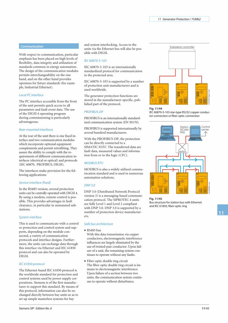
IEC 60870-5-103
IEC 60870-5-103 is an internationallystandardized protocol for communicationin the protected area.
IEC 60870-5-103 is supported by a numberof protection unit manufacturers and isused worldwide.
The generator protection functions arestored in the manufacturer-specific, pub-lished part of the protocol.
PROFIBUS-DP
PROFIBUS is an internationally standard-ized communication system (EN 50170).
PROFIBUS is supported internationally byseveral hundred manufacturers.
With the PROFIBUS-DP, the protectioncan be directly connected to aSIMATIC S5/S7. The transferred data arefault data, measured values and informa-tion from or to the logic (CFC).
MODBUS RTU
MODBUS is also a widely utilized commu-nication standard and is used in numerousautomation solutions.
DNP 3.0
DNP 3.0 (Distributed Network Protocolversion 3) is a messaging-based communi-cation protocol. The SIPROTEC 4 unitsare fully Level 1 and Level 2 compliantwith DNP 3.0. DNP 3.0 is supported by anumber of protection device manufactur-ers.
Safe bus architecture
• RS485 busWith this data transmission via copperconductors, electromagnetic interferenceinfluences are largely eliminated by theuse of twisted-pair conductor. Upon fail-ure of a unit, the remaining system con-tinues to operate without any faults.
• Fiber-optic double ring circuitThe fiber-optic double ring circuit is im-mune to electromagnetic interference.Upon failure of a section between twounits, the communication system contin-ues to operate without disturbance.
Siemens SIP · Edition No. 6
11 Generator Protection / 7UM62
11
11/43
Communication
Fig. 11/44
IEC 60870-5-103 star-type RS232 copper conduc-
tor connection or fiber-optic connection
Fig. 11/45
Bus structure for station bus with Ethernet
and IEC 61850, fiber-optic ring
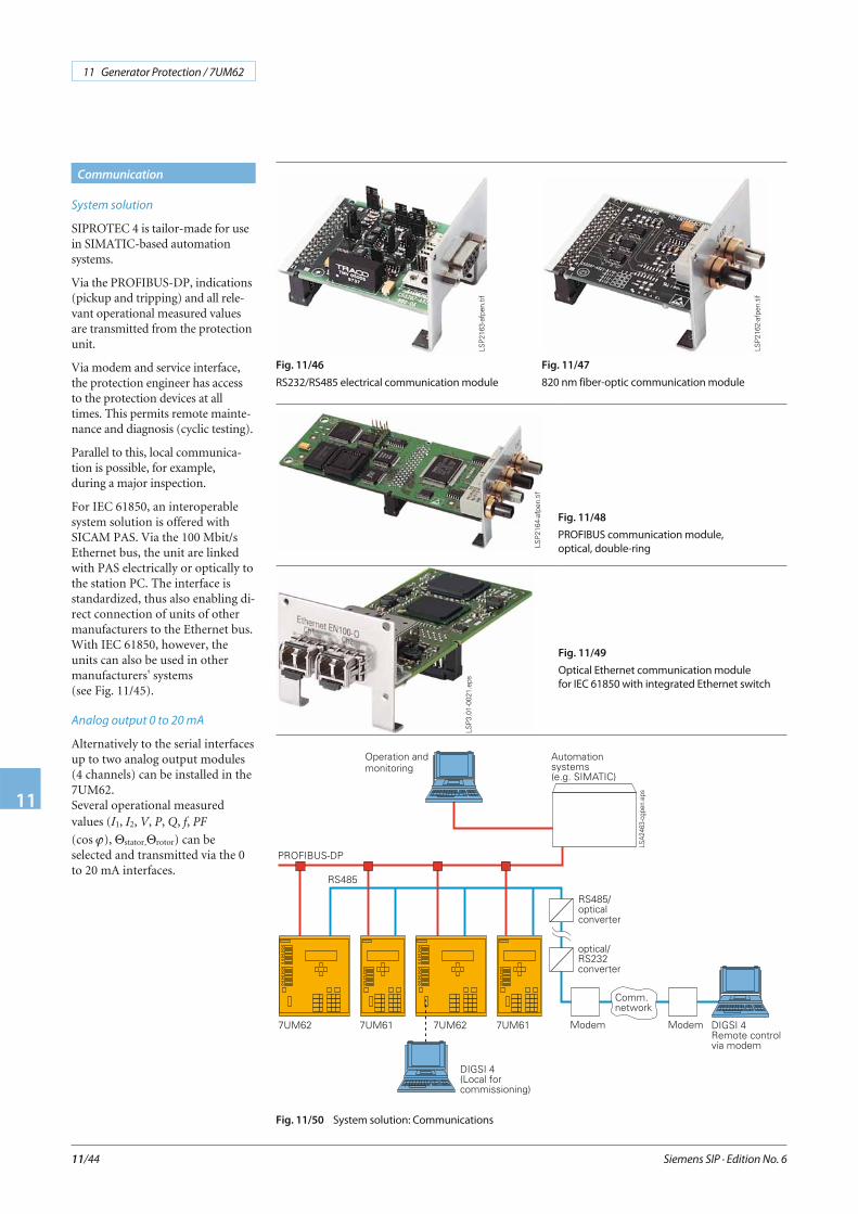
System solution
SIPROTEC 4 is tailor-made for usein SIMATIC-based automationsystems.
Via the PROFIBUS-DP, indications(pickup and tripping) and all rele-vant operational measured valuesare transmitted from the protectionunit.
Via modem and service interface,the protection engineer has accessto the protection devices at alltimes. This permits remote mainte-nance and diagnosis (cyclic testing).
Parallel to this, local communica-tion is possible, for example,during a major inspection.
For IEC 61850, an interoperablesystem solution is offered withSICAM PAS. Via the 100 Mbit/sEthernet bus, the unit are linkedwith PAS electrically or optically tothe station PC. The interface isstandardized, thus also enabling di-rect connection of units of othermanufacturers to the Ethernet bus.With IEC 61850, however, theunits can also be used in othermanufacturers' systems(see Fig. 11/45).
Analog output 0 to 20 mA
Alternatively to the serial interfacesup to two analog output modules(4 channels) can be installed in the7UM62.Several operational measuredvalues (I1, I2, V, P, Q, f, PF
(cos ϕ), Θstator,Θrotor) can beselected and transmitted via the 0to 20 mA interfaces.
Siemens SIP · Edition No. 6
11 Generator Protection / 7UM62
11
11/44
Communication
Fig. 11/47
820 nm fiber-optic communication module
Fig. 11/46
RS232/RS485 electrical communication module
Fig. 11/48
PROFIBUS communication module,
optical, double-ring
Fig. 11/50 System solution: Communications
LSP
2164
-afp
en.ti
f
LSP
2162
-afp
en.ti
f
LSP
2163
-afp
en.ti
f
Fig. 11/49
Optical Ethernet communication module
for IEC 61850 with integrated Ethernet switch
LSP
3.01
-002
1.ep
s
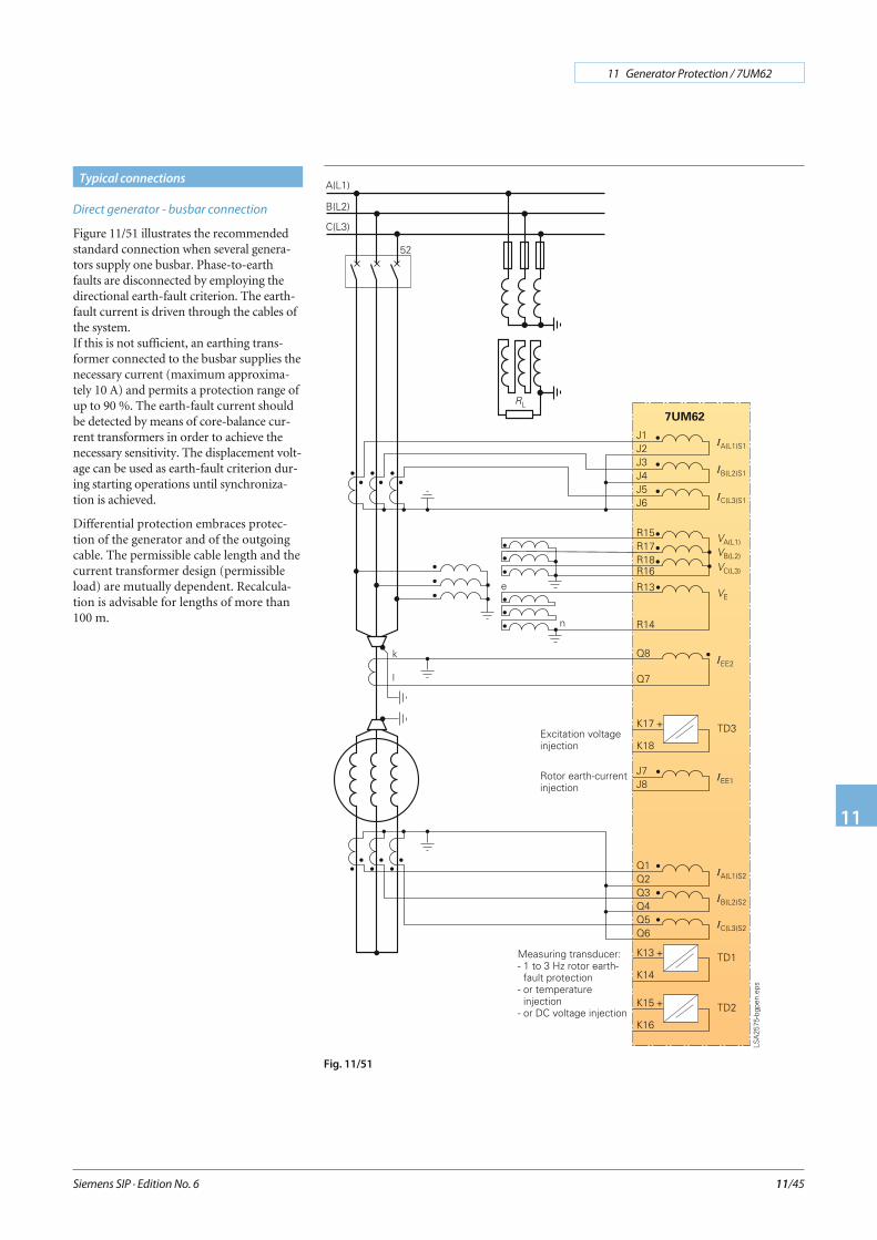
Direct generator - busbar connection
Figure 11/51 illustrates the recommendedstandard connection when several genera-tors supply one busbar. Phase-to-earthfaults are disconnected by employing thedirectional earth-fault criterion. The earth-fault current is driven through the cables ofthe system.If this is not sufficient, an earthing trans-former connected to the busbar supplies thenecessary current (maximum approxima-tely 10 A) and permits a protection range ofup to 90 %. The earth-fault current shouldbe detected by means of core-balance cur-rent transformers in order to achieve thenecessary sensitivity. The displacement volt-age can be used as earth-fault criterion dur-ing starting operations until synchroniza-tion is achieved.
Differential protection embraces protec-tion of the generator and of the outgoingcable. The permissible cable length and thecurrent transformer design (permissibleload) are mutually dependent. Recalcula-tion is advisable for lengths of more than100 m.
Siemens SIP · Edition No. 6
11 Generator Protection / 7UM62
11
11/45
Typical connections
Fig. 11/51
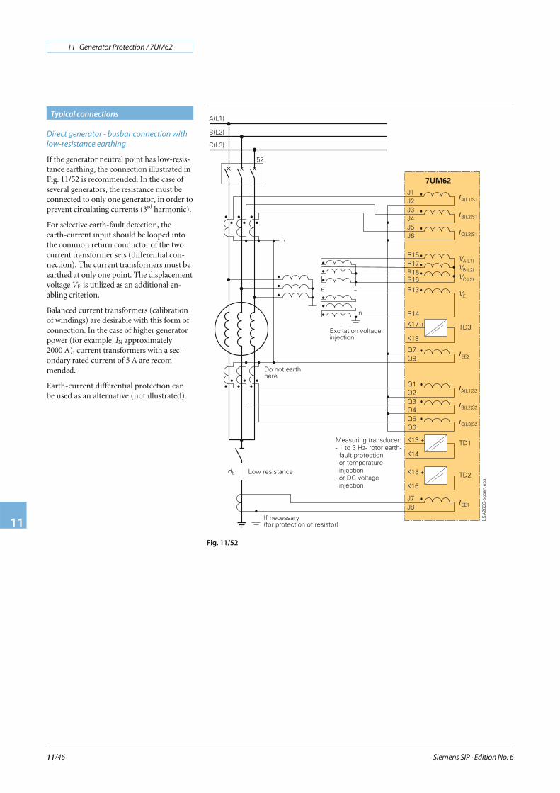
Direct generator - busbar connection with
low-resistance earthing
If the generator neutral point has low-resis-tance earthing, the connection illustrated inFig. 11/52 is recommended. In the case ofseveral generators, the resistance must beconnected to only one generator, in order toprevent circulating currents (3rd harmonic).
For selective earth-fault detection, theearth-current input should be looped intothe common return conductor of the twocurrent transformer sets (differential con-nection). The current transformers must beearthed at only one point. The displacementvoltage VE is utilized as an additional en-abling criterion.
Balanced current transformers (calibrationof windings) are desirable with this form ofconnection. In the case of higher generatorpower (for example, IN approximately2000 A), current transformers with a sec-ondary rated current of 5 A are recom-mended.
Earth-current differential protection canbe used as an alternative (not illustrated).
Siemens SIP · Edition No. 6
11 Generator Protection / 7UM62
11
11/46
Typical connections
Fig. 11/52
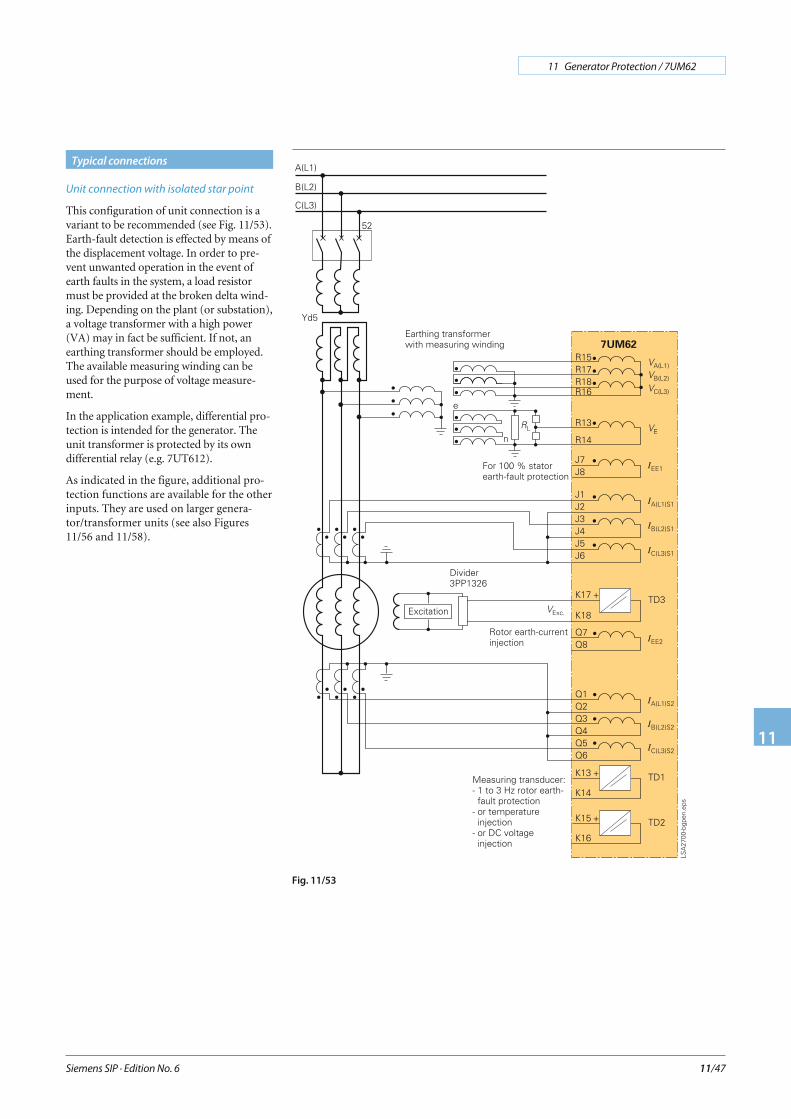
Unit connection with isolated star point
This configuration of unit connection is avariant to be recommended (see Fig. 11/53).Earth-fault detection is effected by means ofthe displacement voltage. In order to pre-vent unwanted operation in the event ofearth faults in the system, a load resistormust be provided at the broken delta wind-ing. Depending on the plant (or substation),a voltage transformer with a high power(VA) may in fact be sufficient. If not, anearthing transformer should be employed.The available measuring winding can beused for the purpose of voltage measure-ment.
In the application example, differential pro-tection is intended for the generator. Theunit transformer is protected by its owndifferential relay (e.g. 7UT612).
As indicated in the figure, additional pro-tection functions are available for the otherinputs. They are used on larger genera-tor/transformer units (see also Figures11/56 and 11/58).
Siemens SIP · Edition No. 6
11 Generator Protection / 7UM62
11
11/47
Typical connections
Fig. 11/53
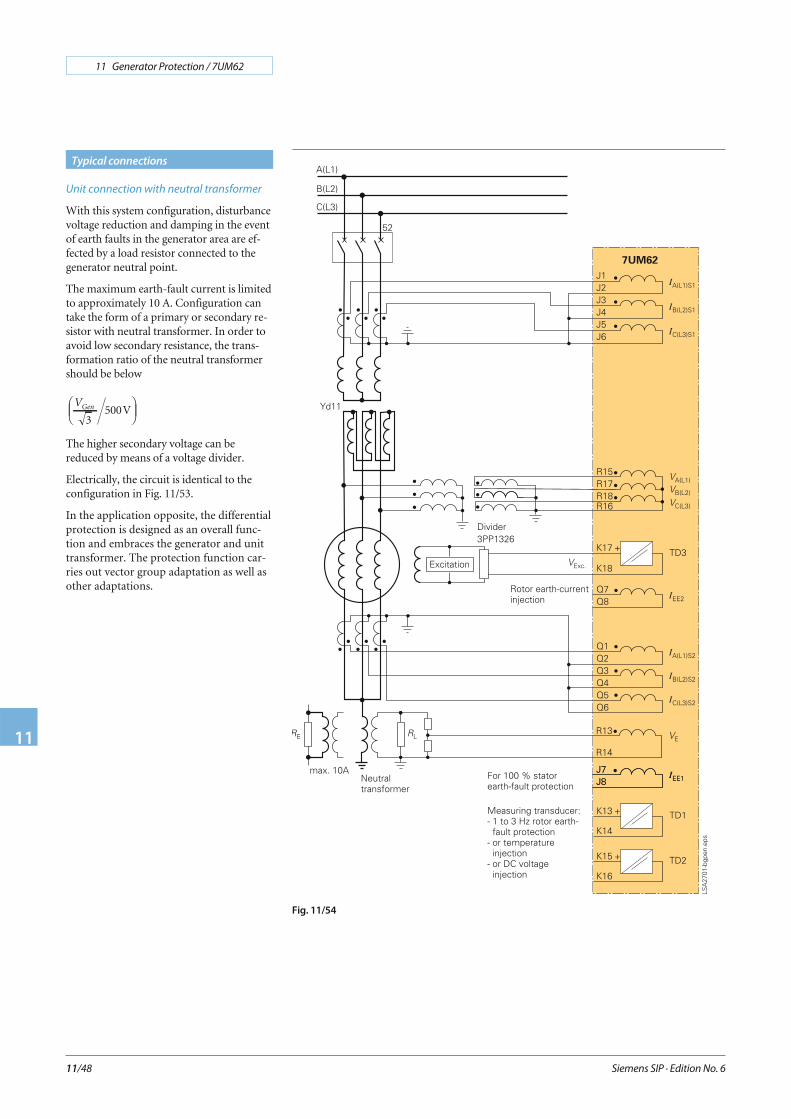
Unit connection with neutral transformer
With this system configuration, disturbancevoltage reduction and damping in the eventof earth faults in the generator area are ef-fected by a load resistor connected to thegenerator neutral point.
The maximum earth-fault current is limitedto approximately 10 A. Configuration cantake the form of a primary or secondary re-sistor with neutral transformer. In order toavoid low secondary resistance, the trans-formation ratio of the neutral transformershould be below
VGen
3500V
⎛⎝⎜
⎞⎠⎟
The higher secondary voltage can bereduced by means of a voltage divider.
Electrically, the circuit is identical to theconfiguration in Fig. 11/53.
In the application opposite, the differentialprotection is designed as an overall func-tion and embraces the generator and unittransformer. The protection function car-ries out vector group adaptation as well asother adaptations.
Siemens SIP · Edition No. 6
11 Generator Protection / 7UM62
11
11/48
Typical connections
Fig. 11/54

Voltage transformer in open delta connec-
tion (V-connection)
Protection can also be implemented onvoltage transformers in open delta connec-tion (Fig. 11/55). If necessary, the opera-tional measured values for the phase-to-earth voltages can be slightly asymmetrical.If this is disturbing, the neutral point (R16)can be connected to earth via acapacitor.
In the case of open delta connection, it isnot possible to calculate the displacementvoltage from the secondary voltages. Itmust be passed to the protection relayalong a different path (for example, voltagetransformer at the generator neutral pointor from the earthing transformer).
100 % stator earth-fault protection,
earth-fault protection during start-up
Fig. 11/56 illustrates the interfacing of100 % stator earth-fault protection withvoltage injection of 20 Hz, as meant for theexample of the neutral transformer. Thesame interfacing connection also applies tothe broken delta winding of the earthingtransformer.
The 20 Hz generator can be connected bothto the DC voltage and also to a powerfulvoltage transformer (>100 VA). The load ofthe current transformer 4NC1225 shouldnot exceed 0.5 Ω.
The 7XT33, 7XT34 and load resistance con-nection must be established with a low resis-tance (RConnection < RL). If large distances arecovered, the devices are accommodated inthe earthing cubicle.
Connection of the DC voltage protectionfunction (TD 1) is shown for systems with astarting converter. Depending on the deviceselection, the 7KG6 boosts the measuredsignal at the shunt to 10 V or 20 mA.
The TD 1 input can be jumpered to the re-levant signal.
Siemens SIP · Edition No. 6
11 Generator Protection / 7UM62
11
11/49
Typical connections
Fig. 11/55
Fig. 11/56
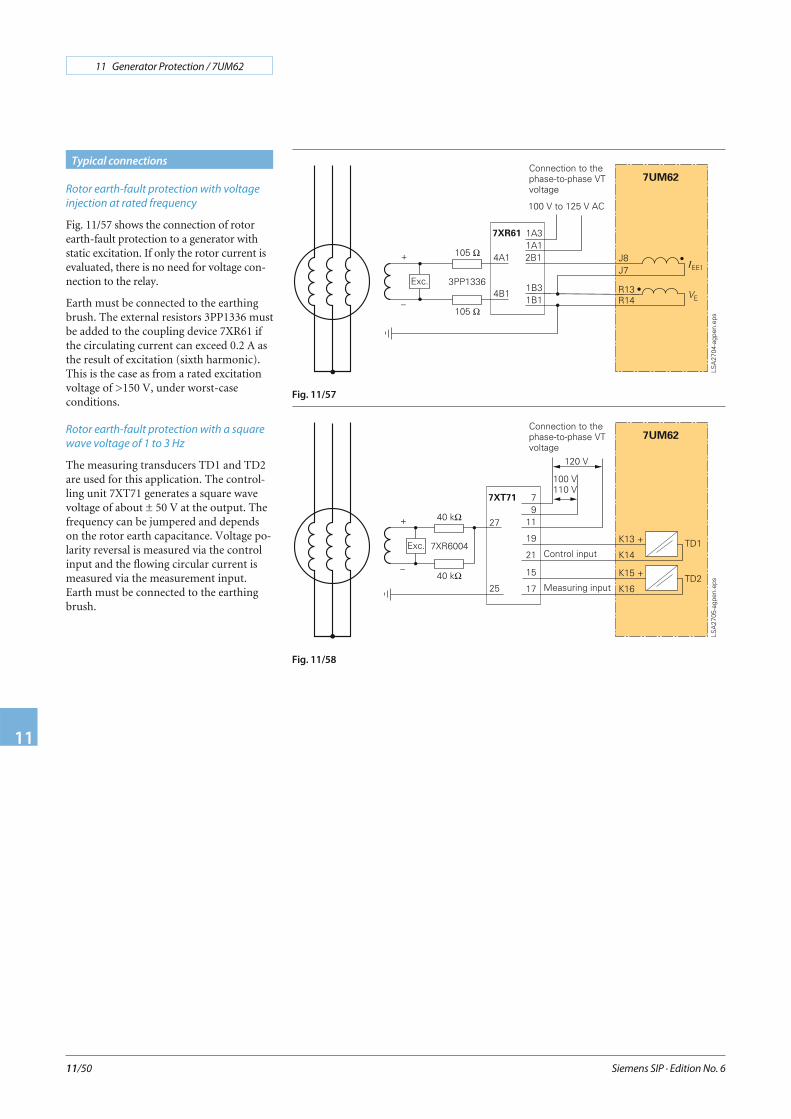
Rotor earth-fault protection with voltage
injection at rated frequency
Fig. 11/57 shows the connection of rotorearth-fault protection to a generator withstatic excitation. If only the rotor current isevaluated, there is no need for voltage con-nection to the relay.
Earth must be connected to the earthingbrush. The external resistors 3PP1336 mustbe added to the coupling device 7XR61 ifthe circulating current can exceed 0.2 A asthe result of excitation (sixth harmonic).This is the case as from a rated excitationvoltage of >150 V, under worst-caseconditions.
Rotor earth-fault protection with a square
wave voltage of 1 to 3 Hz
The measuring transducers TD1 and TD2are used for this application. The control-ling unit 7XT71 generates a square wavevoltage of about ± 50 V at the output. Thefrequency can be jumpered and dependson the rotor earth capacitance. Voltage po-larity reversal is measured via the controlinput and the flowing circular current ismeasured via the measurement input.Earth must be connected to the earthingbrush.
Siemens SIP · Edition No. 6
11 Generator Protection / 7UM62
11
11/50
Typical connections
Fig. 11/57
Fig. 11/58
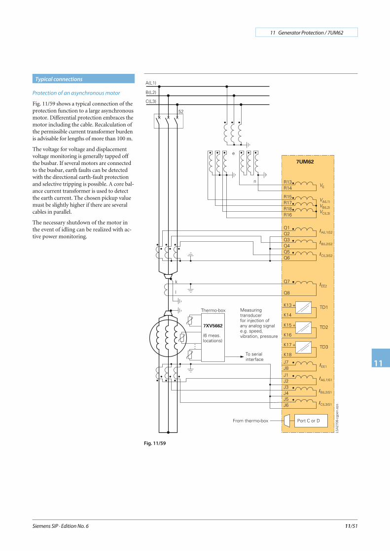
Protection of an asynchronous motor
Fig. 11/59 shows a typical connection of theprotection function to a large asynchronousmotor. Differential protection embraces themotor including the cable. Recalculation ofthe permissible current transformer burdenis advisable for lengths of more than 100 m.
The voltage for voltage and displacementvoltage monitoring is generally tapped offthe busbar. If several motors are connectedto the busbar, earth faults can be detectedwith the directional earth-fault protectionand selective tripping is possible. A core bal-ance current transformer is used to detectthe earth current. The chosen pickup valuemust be slightly higher if there are severalcables in parallel.
The necessary shutdown of the motor inthe event of idling can be realized with ac-tive power monitoring.
Siemens SIP · Edition No. 6
11 Generator Protection / 7UM62
11
11/51
Typical connections
Fig. 11/59
Siemens SIP · Edition No. 6
11 Generator Protection / 7UM62
11
11/52
Typical connections IEE1 IEE2 VE
Sensitive earth-fault protection X1) X1)
Directional stator earth-fault protection X X
Rotor earth-fault protection (fn, R-measuring) X X
100 % stator earth-fault protection with 20 Hz voltage X X
Earth-current differential protection X1) X1)
1) optional (either IEE1 or IEE2)
Table 11/5: Multiple use of analog inputs
TD1 TD2 TD3
Injection of excitation voltage X
DC voltage time/DC current time protection X
Injection of a temperature X
Rotor earth-fault protection (1 to 3 Hz) X X
Processing of analog values via CFC X X X
Table 11/6: Multiple use of measuring transducers
Symmetrical short-circuit limiting factor
Required actual accuracy limiting factor
K' Kssc tdpssc
pn
= ⋅I
I
Resulting rated accuracy limiting factor
K K'sscb Ct
BN Ctssc= +
+⋅R R
R R
'
Current transformer requirements
Transformer Generator
Transient dimensioning factor Ktd ≥ 4τN ≤ 100 ms
> (4 to 5)τN > 100 ms
Symmetrical short-circuit current Ipssc ≈1
v scpn, Tr⋅ I ≈ ⋅1
x"dpn, GI
Example vsc = 0.1K'ssc > 40
x”d = 0.12K'ssc > (34 to 42)
Note:Identical transformers have to be employed
Rated power ≥ 10 or15 VA
Example:Network transformer10P10: (10 or 15) VA(Isn = 1 or 5 A)
Note: Secondarywinding resistance
Example:IN, G approx. 1000 to 2000 A5P15: 15 VA(Isn = 1 or 5 A)
IN, G > 5 000 A5P20: 30 VA(Isn = 1 or 5 A)
Knee-point voltage
IEC British Standard ANSI
( )V R R= +Kssc ct b snI( )
VR R
=+ct b sn
sscKI
13.( )V R R= ⋅ ⋅ + ⋅20
20Isn ct b
sscK
Isn A= 5 (typical value)
Ktd Rated transient dimensioning factor Rct Secondary winding resistanceIpssc Primary symmetrical short-circuit current vsc Short-circuit voltage (impedance voltage)Ipn Rated primary current (transformer) x”d Subtransient reactanceR'b Connected burden Isn Rated secondary current (transformer)Rb Rated resistive burden τN Network time constant
Table 11/7: Recommendations for dimensioning
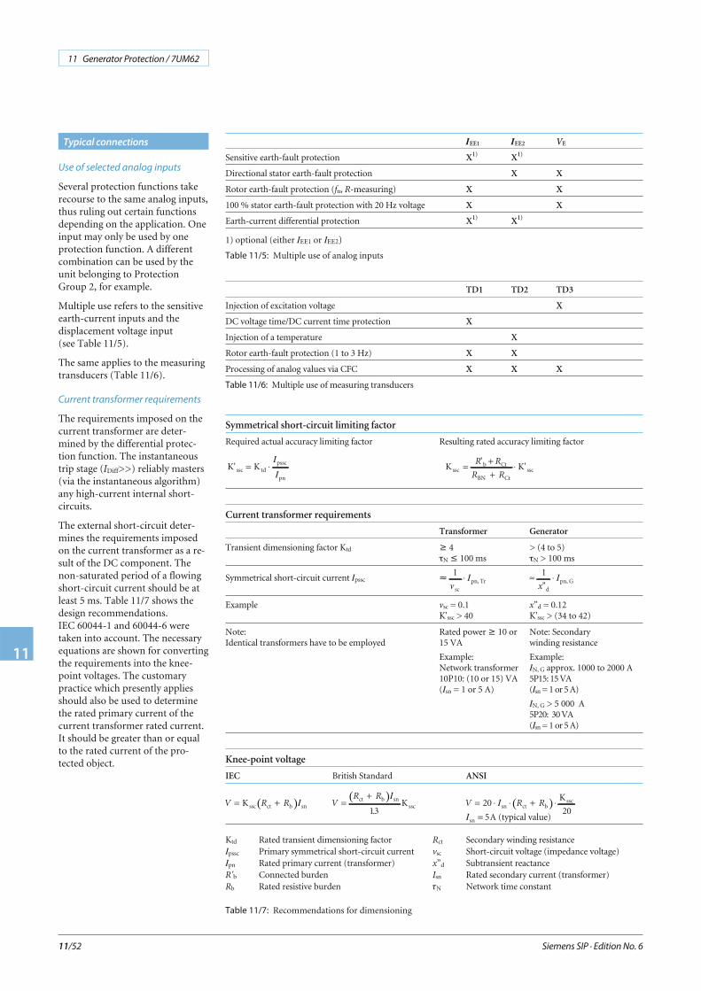
Use of selected analog inputs
Several protection functions takerecourse to the same analog inputs,thus ruling out certain functionsdepending on the application. Oneinput may only be used by oneprotection function. A differentcombination can be used by theunit belonging to ProtectionGroup 2, for example.
Multiple use refers to the sensitiveearth-current inputs and thedisplacement voltage input(see Table 11/5).
The same applies to the measuringtransducers (Table 11/6).
Current transformer requirements
The requirements imposed on thecurrent transformer are deter-mined by the differential protec-tion function. The instantaneoustrip stage (IDiff>>) reliably masters(via the instantaneous algorithm)any high-current internal short-circuits.
The external short-circuit deter-mines the requirements imposedon the current transformer as a re-sult of the DC component. Thenon-saturated period of a flowingshort-circuit current should be atleast 5 ms. Table 11/7 shows thedesign recommendations.IEC 60044-1 and 60044-6 weretaken into account. The necessaryequations are shown for convertingthe requirements into the knee-point voltages. The customarypractice which presently appliesshould also be used to determinethe rated primary current of thecurrent transformer rated current.It should be greater than or equalto the rated current of the pro-tected object.

Siemens SIP · Edition No. 6
11 Generator Protection / 7UM62
11
11/53
Technical data
Hardware
Analog input
Rated frequency 50 or 60 Hz
Rated current IN 1 or 5 A
Earth current, sensitive IEmax 1.6 A
Rated voltage VN (at 100 V) 100 to 125 V
Measuring transducer - 10 to + 10 V (Ri = 1 MΩ) or- 20 to + 20 mA (Ri = 10 Ω)
Power consumptionWith IN = 1 AWith IN = 5 AFor sensitive earth currentVoltage inputs (with 100 V)
Approx. 0.05 VAApprox. 0.3 VAApprox. 0.05 VAApprox. 0.3 VA
Capability in CT circuitsThermal (r.m.s. values)
Dynamic (peak)
100 IN for 1 s30 IN for 10 s4 IN continuous
250 IN (one half cycle)
Earth current, sensitive
Dynamic (peak)
300 A for 1 s100 A for 10 s15 A continuous750 A (one half cycle)
Capability in voltage paths 230 V continuous
Capability of measuring transducerAs voltage inputAs current input
60 V continuous100 mA continuous
Auxiliary voltage
Rated auxiliary voltage 24 to 48 V DC60 to 125 V DC110 to 250 V DCand 115 V/230 V AC with 50/60 Hz
Permitted tolerance –20 to +20 %
Superimposed (peak-to-peak) ≤ 15 %
Power consumptionDuring normal operation
7UM6217UM6227UM623
During pickup with all inputsand outputs activated
7UM6217UM6227UM623
Approx. 5.3 WApprox. 5.5 WApprox. 8.1 W
Approx. 12 WApprox. 15 WApprox. 14.5 W
Bridging time during auxiliary volt-age failure
at Vaux = 48 V and Vaux ≥ 110 Vat Vaux = 24 V and Vaux = 60 V
≥ 50 ms≥ 20 ms
Binary inputs
Number7UM621, 7UM6237UM622
715
3 pickup thresholdsRange is selectable with jumpers
10 to 19 V DC or 44 to 88 V DC88 to 176 V DC
Maximum permissible voltage 300 V DC
Current consumption, energized Approx. 1.8 mA
Output relays
Number7UM621
7UM622
12 (1 NO; 4 optional as NC,via jumper)21 (1 NO; 5 optional as NC,via jumper)
Switching capacityMakeBreakBreak (for resistive load)Break (for L/R ≤ 50 ms)
1000 W / VA30 VA40 W25 VA
Switching voltage 250 V
Permissible current 5 A continuous30 A for 0.5 seconds
LED
NumberRUN (green)ERROR (red)
11
Assignable LED (red) 14
Unit design
7XP20 housing For dimensions see dimensiondrawings, part 15
Degree of protection acc. toEN 60529
For surface-mounting housingFor flush-mounting housing
FrontRear
For the terminals
IP 51
IP 51IP 50IP 2x with terminal cover put on
WeightFlush-mounting housing
7UM621/7UM623 (1/2 x 19”)
7UM622 (1/1 x 19”)
Surface-mounting housing7UM621/7UM623 (1/2 x 19’‘)
7UM622 (1/1 x 19’‘)
Approx. 7 kgApprox. 9.5 kg
Approx. 12 kgApprox. 15 kg
Serial interfaces
Operating interface for DIGSI 4
Connection Non-isolated, RS232, front panel;9-pin subminiature connector
Baud rate 4800 to 115200 baud
Time synchronization IRIG B / DCF 77 signal (Format: IRIG-B000)
Connection 9-pin subminiature connector,terminal with surface-mounting case
Voltage levels Selectable 5 V, 12 V or 24 V
Service/modem interface (Port C) for DIGSI 4 / modem / service
Isolated RS232/RS485Test voltageDistance for RS232Distance for RS485
9-pin subminiature connector500 V / 50 HzMax. 15 mMax. 1000 m
Siemens SIP · Edition No. 6
11 Generator Protection / 7UM62
11
11/54
System interface (Port B)
IEC 60870-5-103 protocol, PROFIBUS-DP, MODBUS RTU
Isolated RS232/RS485Baud rateTest voltageDistance for RS232Distance for RS485
9-pin subminiature connector4800 to 115200 baud500 V / 50 HzMax. 15 mMax. 1000 m
PROFIBUS RS485Test voltageBaud rateDistance
500 V / 50 HzMax. 12 MBaud1000 m at 93.75 kBaud;100 m at 12 MBaud
PROFIBUS fiber-opticOnly for flush-mounting housingFor surface-mounting housingBaud rateOptical wavelengthPermissible path attenuationDistance
ST connectorOptical interface with OLM1)
Max. 1.5 MBaudλ = 820 nmMax. 8 dB for glass-fiber 62.5/125 μm1.6 km (500 kB/s)530 m (1500 kB/s)
Analog output module (electrical) 2 ports with 0 to 20 mA
System interface (Port B)
IEC 61850
Ethernet, electrical (EN 100) for IEC 61850 and DIGSI
Connectionfor flush-mounting case
for surface-mounting caseTest voltageTransmission speedDistance
Rear panel, mounting location "B",two RJ45 connector, 100 Mbit/s acc.to IEEE802.3At bottom part of the housing500 V; 50 Hz100 Mbits/s20 m/66 ft
Ethernet, optical (EN 100) for IEC 61850 and DIGSI
Connectionfor flush-mounting case
for panel surface-mounting caseOptical wavelengthTransmission speedLaser class 1 acc. to EN 60825-1/-2
Permissible path attenuationDistance
Rear panel, mounting location "B",LC connector receiver/transmitterNot availableλ = 1350 nm100 Mbits/sGlass fiber 50/125 μm orglass fiber 62/125μmMax. 5 dB for glass fiber 62.5/125 μmMax. 800 m/0.5 mile
Electrical tests
Specifications
Standards IEC 60255 (product standards)ANSI/IEEE C37.90.0/.1/.2UL 508DIN 57435, part 303For further standards see below
Insulation tests
Standards IEC 60255-5
Voltage test (100 % test)All circuits except for auxiliary sup-ply, binary inputs communicationand time synchronization interfaces
2.5 kV (r.m.s.), 50/60 Hz
Voltage test (100 % test)Auxiliary voltage and binary inputs
3.5 kV DC
Voltage test (100 % test)only isolated communication inter-faces and time synchronization inter-face
500 V (r.m.s. value), 50/60 Hz
Technical data
Impulse voltage test (type test)All circuits except for communicationinterfaces and time synchronizationinterface, class III
5 kV (peak); 1.2/50 μs; 0.5 J;3 positive and 3 negative impulsesat intervals of 5 s
EMC tests for noise immunity; type test
Standards IEC 60255-6, IEC 60255-22(product standards)EN 50082-2 (generic standard)DIN 57435 part 303
High frequency testIEC 60255-22-1, class IIIand DIN 57435 part 303, class III
2.5 kV (peak value), 1 MHz;τ = 15 ms400 pulses per s; duration 2 s
Electrostatic dischargeIEC 60255-22-2 class IVEN 61000-4-2, class IV
8 kV contact discharge;15 kV air discharge;both polarities; 150 pF; Ri = 330 Ω
Irradiation with RF field,non-modulatedIEC 60255-22-3 (report), class III
10 V/m; 27 to 500 MHz
Irradiation with RF field, amplitude-modulated, IEC 61000-4-3, class III
10 V/m; 80 to 1000 MHz; 80 % AM;1 kHz
Irradiation with RF field,pulse-modulatedIEC 61000-4-3/ ENV 50204, class III
10 V/m; 900 MHz; repetitionfrequency 200 Hz; duty cycle 50 %
Fast transient interference burstsIEC 60255-22-4,IEC 61000-4-4, class IV
4 kV; 5/50 ns; 5 kHz;burst length = 15 ms; repetitionrate 300 ms; both polarities;Ri = 50 Ω; test duration 1 min
High-energy surge voltages (SURGE),IEC 61000-4-5 installation, class IIIAuxiliary supply
Impulse: 1.2/50 μs
Common (longitudinal) mode:2 kV; 12 Ω, 9 μFDifferential (transversal) mode:1 kV; 2 Ω, 18 μF
Measurement inputs, binary inputsand relay outputs
Common (longitudinal) mode:2 kV; 42 Ω, 0.5 μFDifferential (transversal) mode:1 kV; 42 Ω, 0.5 μF
Line-conducted HF,amplitude-modulatedIEC 61000-4-6, class III
10 V; 150 kHz to 80 MHz; 80 % AM;1 kHz
Magnetic field with power frequencyIEC 61000-4-8, class IV; IEC 60255-6
30 A/m continuous;300 A/m for 3 s; 50 Hz0.5 mT; 50 Hz
Oscillatory surge withstandcapabilityANSI/IEEE C37.90.1
2.5 to 3 kV (peak); 1 to 1.5 MHzdamped wave; 50 surges per second;duration 2 s; Ri = 150 to 200 Ω
Fast transient surge withstandcapabilityANSI/IEEE C37.90.1
4 to 5 kV; 10/150 ns; 50 surges persecond; both polarities; duration 2 s;Ri = 80 Ω
Radiated electromagnetic interferenceANSI/IEEE C37.90.2
35 V/m; 25 to 1000 MHz
Damped oscillationsIEC 60894, IEC 61000-4-12
2.5 kV (peak value), polarity alter-nating 100 kHz, 1 MHz, 10 and50 MHz, Ri = 200 Ω
1) Conversion with external OLMFor fiber-optic interface please complete order number at 11th positionwith 4 (FMS RS485) or 9 and Order code L0A (DP RS485) and addi-tionally order:For single ring: SIEMENS OLM 6GK1502-3AB10For double ring: SIEMENS OLM 6GK1502-4AB10
Siemens SIP · Edition No. 6
11 Generator Protection / 7UM62
11
11/55
EMC tests for interference emission; type tests
Standard EN 50081-1 (generic standard)
Conducted interference voltage onlinesonly auxiliary supply IEC-CISPR 22
150 kHz to 30 MHzLimit class B
Interference field strengthIEC-CISPR 22
30 to 1000 MHzLimit class B
Mechanical stress tests
Vibration, shock stress and seismic vibration
During operation
Standards IEC 60255-21 and IEC 60068
VibrationIEC 60255-21-1, class 2IEC 60068-2-6
Sinusoidal10 to 60 Hz: ± 0.075 mm amplitude;60 to 150 Hz: 1 g accelerationFrequency sweep 1 octave/min20 cycles in 3 orthogonal axes
ShockIEC 60255-21-2, class 1IEC 60068-2-27
Half-sinusoidalAcceleration 5 g, duration 11 ms,3 shocks each in both directions ofthe 3 axes
Seismic vibrationIEC 60255-21-2, class 1IEC 60068-3-3
Sinusoidal1 to 8 Hz: ± 3.5 mm amplitude(horizontal axis)1 to 8 Hz: ± 1.5 mm amplitude(vertical axis)8 to 35 Hz: 1 g acceleration(horizontal axis)8 to 35 Hz: 0.5 g acceleration(vertical axis)Frequency sweep 1 octave/min1 cycle in 3 orthogonal axes
During transport
Standards IEC 60255-21 and IEC 60068-2
VibrationIEC 60255-21-1, class 2IEC 60068-2-6
Sinusoidal5 to 8 Hz: ±7.5 mm amplitude;8 to 150 Hz: 2 g accelerationFrequency sweep 1 octave/min20 cycles in 3 orthogonal axes
ShockIEC 60255-21-2, class 1IEC 60068-2-27
Half-sinusoidalAcceleration 15 g, duration 11 ms,3 shocks each in both directions3 axes
Continuous shockIEC 60255-21-2, class 1IEC 60068-2-29
Half-sinusoidalAcceleration 10 g, duration 16 ms,1000 shocks in both directions of the3 axes
Climatic stress test
Temperatures
Type-tested acc. to IEC 60068-2-1and -2, test Bd, for 16 h
–25 °C to +85 °C / –13 °F to +185 °F
Temporarily permissible operatingtemperature, tested for 96 h
–20 °C to +70 °C / –4 °F to +158 °F
Recommended permanent operatingtemperature acc. to IEC 60255-6(Legibility of display may be impairedabove +55 °C / +131 °F)
–5 °C to +55 °C / +25 °F to +131 °F
– Limiting temperature duringpermanent storage
– Limiting temperature duringtransport
–25 °C to +55 °C / –13 °F to +131 °F
–25 °C to +70 °C / –13 °F to +158 °F
Technical data
Humidity
Permissible humidity stressIt is recommended to arrange theunits in such a way that they are notexposed to direct sunlight or pro-nounced temperature changes thatcould cause condensation
Annual average ≤ 75 % relative hu-midity; on 56 days a year up to 93 %relative humidity; condensation isnot permitted
Functions
General
Frequency range 11 to 69 Hz
Definite-time overcurrent protection, directional (ANSI 50, 51, 67)
Setting rangesOvercurrent I>, I>>
Time delay TUndervoltage seal-in V<Seal-in time of V<Angle of the directional element(at I>>)
0.05 to 20 A (steps 0.01 A);5 times at IN = 5 A0 to 60 s (steps 0.01 s) or indefinite10 to 125 V (steps 0.1 V)0.1 to 60 s (steps 0.01 s)- 90 ° to + 90 ° (steps 1 °)
TimesPickup time I>, I>>at 2 times of set valueat 10 times of set valueDrop-off time I>, I>>
Approx. 35 msApprox. 25 msApprox. 50 ms
Drop-off ratioDrop-off ratio V<
I>: 0.95; I>>: 0.9 to 0.99 (steps 0.01)Approx. 1.05
TolerancesCurrent pickup (starting) I>, I>>Undervoltage seal-in V<Angle of the directional elementTime delays
1 % of set value or 10/50 mA1 % of set value or 0.5 V1 °1 % or 10 ms
Inverse-time overcurrent protection (ANSI 51V)
Setting rangesPickup overcurrent IP
Time multiplierIEC-characteristics T
Time multiplier ANSI-characteristics D
Undervoltage release V<
0.1 to 4 A (steps 0.01 A); 5 times atIN = 5A0.05 to 3.2 s (steps 0,01 s)or indefinite
0.5 to 15 (steps 0.01) or indefinite
10 to 125 V (steps 0.1 V)
Trip characteristicsIEC
ANSI
Pickup thresholdDrop-off threshold
Normal inverse; very inverse;extremely inverseInverse; moderately inverse;very inverse; extremely inverse;definite inverseApprox. 1.1 IP
Approx. 1.05 IP for IP/IN ≥ 0.3
TolerancesPickup threshold IP
Pickup threshold V<Time for 2 ≤ I/IP ≤ 20
1 % of set value or 10/50 mA1 % of set value or 0.5 V5 % of nominal value + 1 % currenttolerance or 40 ms
Siemens SIP · Edition No. 6
11 Generator Protection / 7UM62
11
11/56
Technical data
Stator overload protection, thermal (ANSI 49)
Setting rangesFactor k according to IEC 60255-8Time constantTime delay factor at stand stillAlarm overtemperatureΘAlarm/ΘTrip
Overcurrent alarm stage IAlarm
Temperature at IN
Scaling temperature of coolingmedium
Limit current ILimit
Reset time at emergency start
0.5 to 2.5 (steps 0.01)30 to 32000 s (steps 1 s)1 to 10 (steps 0.01)70 to 100 % related to the triptemperature (steps 1 %)0.1 to 4 A (steps 0.01 A); 5 times atIN = 5 A40 to 200 °C (steps 1 °C)or 104 to 392 °F (steps 1 °F)40 to 300 °C (steps 1 °C)or 104 to 572 °F (steps 1 °F)
0.5 to 8 A (steps 0.01), 5 times atIN = 5 A
20 to 150000 s (steps 1 s)
Drop-off ratioΘ / ΘTrip
Θ / ΘAlarrm
I/IAlarm
Drop-off with ΘAlarrn
Approx. 0.99Approx. 0.95
TolerancesRegarding k x IN
Regarding trip time
2 % or 10/50 mA; class 2 % accord-ing to IEC 60255-83 % or 1 s: class 3 % according toIEC 60255-8 for I/(k IN)>1.25
Negative-sequence protection (ANSI 46)
Setting rangesPermissible negative sequenceI2 perm. /IN
Definite time trip stage I2 >>/IN
Time delays TAlarm; TI2>>Negative-sequence factor KCooling down time TCooling
3 to 30 % (steps 1 %)
10 to 200 % (steps 1 %)0 to 60 s (steps 0.01 s) or indefinite1 to 40 s (steps 0.1 s)0 to 50000 s (steps 1 s)
TimesPickup time (definite stage)Drop-off time (definite stage)
Approx. 50 msApprox. 50 ms
Drop-off ratios I2 perm.; I2 >>Drop-off ratio thermal stage
Approx. 0.95Drop-off at fall below of I2 perm.
TolerancesPickup values I2 perm.; I2 >>
Time delaysThermal characteristic
Time for 2 ≤ I2/I2 perm. ≤ 20
3 % of set value or 0.3 % negativesequence1 % or 10 ms5 % of set point + 1 % current toler-anceor 600 ms
Underexcitation protection (ANSI 40)
Setting rangesConductance thresholds 1/xdcharacteristic(3 characteristics)Inclination angle α1, α2, α3
Time delay TUndervoltage blocking V<
0.20 to 3.0 (steps 0.01)
50 to 120 ° (steps 1 °)0 to 50 s (steps 0.01 s) or indefinite10 to 125 V (steps 0.1 V)
TimesStator criterion 1/xd characteristic; αUndervoltage blocking
Approx. 60 msApprox. 50 ms
Drop-off ratioStator criterion 1/xd characteristic; αUndervoltage blocking
Approx. 0.95Approx. 1.1
TolerancesStator criterion 1/xd characteristicStator criterion αUndervoltage blockingTime delays T
3 % of set value1 ° electrical1 % or 0.5 V1 % or 10 ms
Reverse-power protection (ANSI 32R)
Setting rangesReverse power PRev.>/SN
Time delays T- 0.5 to - 30 % (steps 0.01 %)0 to 60 s (steps 0.01 s) or indefinite
TimesPickup time
Drop-off time
Approx. 360 ms (50 Hz);Approx. 300 ms (60 Hz)Approx. 360 ms (50 Hz);Approx. 300 ms (60 Hz)
Drop-off ratio PRev.> Approx. 0.6
TolerancesReverse power PRev.>Time delays T
0.25 % SN ± 3 % set value1 % or 10 ms
Forward-power protection (ANSI 32F)
Setting rangesForward power PForw.</SN
Forward power PForw.>/SN
Time delays T
0.5 to 120 % (steps 0.1 %)1 to 120 % (steps 0.1 %)0 to 60 s (steps 0.01 s) or indefinite
TimesPickup time (accurate measuring)
Pickup time (fast measuring)
Drop-off time (accurate measuring)
Drop-off time (fast measuring)
Approx. 360 ms (50 Hz);Approx. 300 ms (60 Hz)Approx. 60 ms (50 Hz);Approx. 50 ms (60 Hz)Approx. 360 ms (50 Hz);Approx. 300 ms (60 Hz)Approx. 60 ms (50 Hz);Approx. 50 ms (60 Hz)
Drop-off ratio PForw.<Drop-off ratio PForw.>
1.1 or 0.5 % of SN
Approx. 0.9 or – 0.5 % of SN
TolerancesActive power PForw.<, PForw.>
Time delays T
0.25 % SN ± 3 % of set valueat Q < 0.5 SN at accurate measuring0.5 % SN ± 3 % of set valueat Q < 0.5 SN at fast measuring1 % or 10 ms
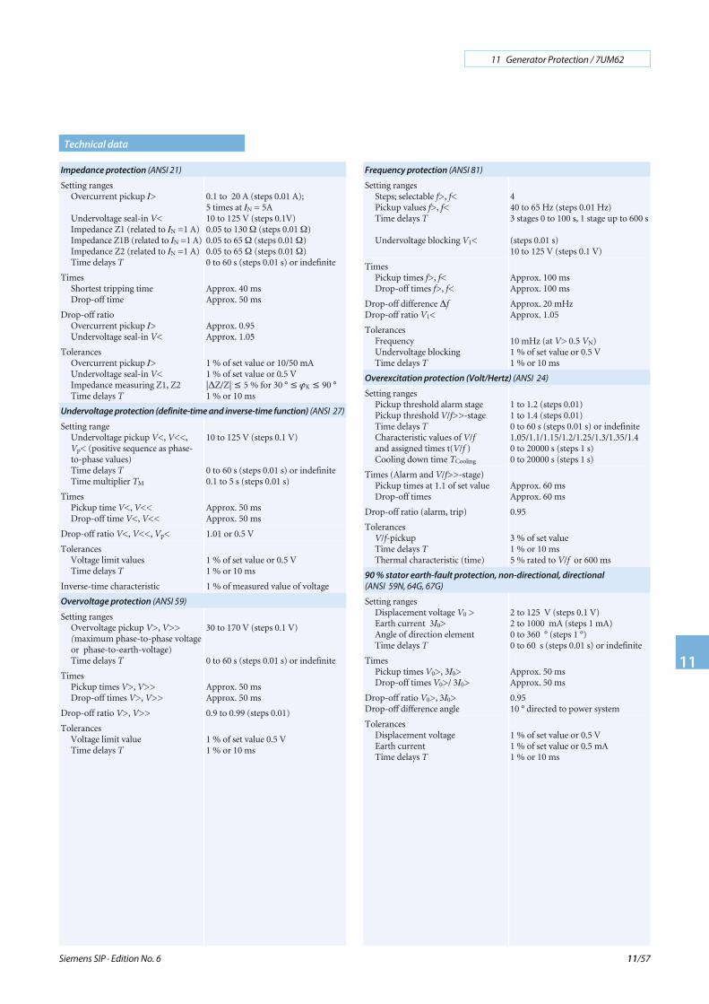
Siemens SIP · Edition No. 6
11 Generator Protection / 7UM62
11
11/57
Technical data
Frequency protection (ANSI 81)
Setting rangesSteps; selectable f>, f<Pickup values f>, f<Time delays T
Undervoltage blocking V1<
440 to 65 Hz (steps 0.01 Hz)3 stages 0 to 100 s, 1 stage up to 600 s
(steps 0.01 s)10 to 125 V (steps 0.1 V)
TimesPickup times f>, f<Drop-off times f>, f<
Approx. 100 msApprox. 100 ms
Drop-off difference ΔfDrop-off ratio V1<
Approx. 20 mHzApprox. 1.05
TolerancesFrequencyUndervoltage blockingTime delays T
10 mHz (at V> 0.5 VN)1 % of set value or 0.5 V1 % or 10 ms
Overexcitation protection (Volt/Hertz) (ANSI 24)
Setting rangesPickup threshold alarm stagePickup threshold V/f>>-stageTime delays TCharacteristic values of V/fand assigned times t(V/f )Cooling down time TCooling
1 to 1.2 (steps 0.01)1 to 1.4 (steps 0.01)0 to 60 s (steps 0.01 s) or indefinite1.05/1.1/1.15/1.2/1.25/1.3/1.35/1.40 to 20000 s (steps 1 s)0 to 20000 s (steps 1 s)
Times (Alarm and V/f>>-stage)Pickup times at 1.1 of set valueDrop-off times
Approx. 60 msApprox. 60 ms
Drop-off ratio (alarm, trip) 0.95
TolerancesV/f-pickupTime delays TThermal characteristic (time)
3 % of set value1 % or 10 ms5 % rated to V/f or 600 ms
90 % stator earth-fault protection, non-directional, directional
(ANSI 59N, 64G, 67G)
Setting rangesDisplacement voltage V0 >Earth current 3I0>Angle of direction elementTime delays T
2 to 125 V (steps 0.1 V)2 to 1000 mA (steps 1 mA)0 to 360 ° (steps 1 °)0 to 60 s (steps 0.01 s) or indefinite
TimesPickup times V0>, 3I0>Drop-off times V0>/ 3I0>
Approx. 50 msApprox. 50 ms
Drop-off ratio V0>, 3I0>Drop-off difference angle
0.9510 ° directed to power system
TolerancesDisplacement voltageEarth currentTime delays T
1 % of set value or 0.5 V1 % of set value or 0.5 mA1 % or 10 ms
Impedance protection (ANSI 21)
Setting rangesOvercurrent pickup I>
Undervoltage seal-in V<Impedance Z1 (related to IN =1 A)Impedance Z1B (related to IN =1 A)Impedance Z2 (related to IN =1 A)Time delays T
0.1 to 20 A (steps 0.01 A);5 times at IN = 5A10 to 125 V (steps 0.1V)0.05 to 130 Ω (steps 0.01 Ω)0.05 to 65 Ω (steps 0.01 Ω)0.05 to 65 Ω (steps 0.01 Ω)0 to 60 s (steps 0.01 s) or indefinite
TimesShortest tripping timeDrop-off time
Approx. 40 msApprox. 50 ms
Drop-off ratioOvercurrent pickup I>Undervoltage seal-in V<
Approx. 0.95Approx. 1.05
TolerancesOvercurrent pickup I>Undervoltage seal-in V<Impedance measuring Z1, Z2Time delays T
1 % of set value or 10/50 mA1 % of set value or 0.5 V|ΔZ/Z| ≤ 5 % for 30 ° ≤ ϕK ≤ 90 °1 % or 10 ms
Undervoltage protection (definite-time and inverse-time function) (ANSI 27)
Setting rangeUndervoltage pickup V<, V<<,Vp< (positive sequence as phase-to-phase values)Time delays TTime multiplier TM
10 to 125 V (steps 0.1 V)
0 to 60 s (steps 0.01 s) or indefinite0.1 to 5 s (steps 0.01 s)
TimesPickup time V<, V<<Drop-off time V<, V<<
Approx. 50 msApprox. 50 ms
Drop-off ratio V<, V<<, Vp< 1.01 or 0.5 V
TolerancesVoltage limit valuesTime delays T
1 % of set value or 0.5 V1 % or 10 ms
Inverse-time characteristic 1 % of measured value of voltage
Overvoltage protection (ANSI 59)
Setting rangesOvervoltage pickup V>, V>>(maximum phase-to-phase voltageor phase-to-earth-voltage)Time delays T
30 to 170 V (steps 0.1 V)
0 to 60 s (steps 0.01 s) or indefinite
TimesPickup times V>, V>>Drop-off times V>, V>>
Approx. 50 msApprox. 50 ms
Drop-off ratio V>, V>> 0.9 to 0.99 (steps 0.01)
TolerancesVoltage limit valueTime delays T
1 % of set value 0.5 V1 % or 10 ms
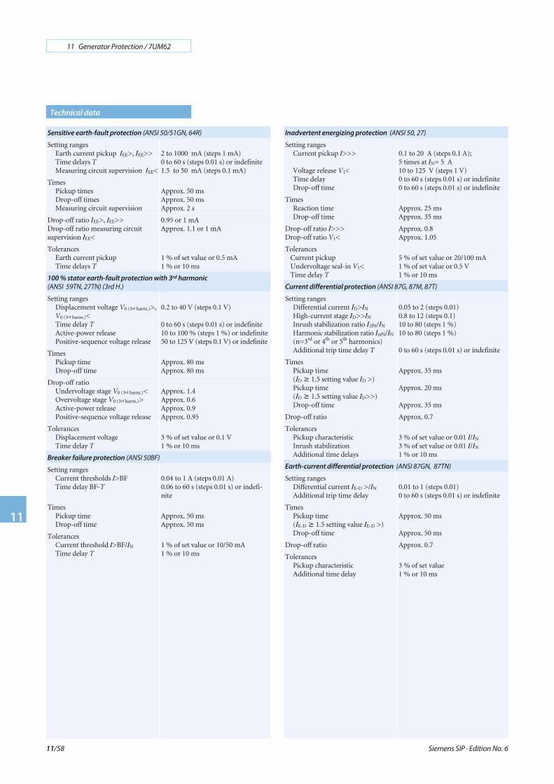
Siemens SIP · Edition No. 6
11 Generator Protection / 7UM62
11
11/58
Sensitive earth-fault protection (ANSI 50/51GN, 64R)
Setting rangesEarth current pickup IEE>, IEE>>Time delays TMeasuring circuit supervision IEE<
2 to 1000 mA (steps 1 mA)0 to 60 s (steps 0.01 s) or indefinite1.5 to 50 mA (steps 0.1 mA)
TimesPickup timesDrop-off timesMeasuring circuit supervision
Approx. 50 msApprox. 50 msApprox. 2 s
Drop-off ratio IEE>, IEE>>Drop-off ratio measuring circuitsupervision IEE<
0.95 or 1 mAApprox. 1.1 or 1 mA
TolerancesEarth current pickupTime delays T
1 % of set value or 0.5 mA1 % or 10 ms
100 % stator earth-fault protection with 3rd harmonic
(ANSI 59TN, 27TN) (3rd H.)
Setting rangesDisplacement voltage V0 (3rd harm.)>,V0 (3rd harm.)<Time delay TActive-power releasePositive-sequence voltage release
0.2 to 40 V (steps 0.1 V)
0 to 60 s (steps 0.01 s) or indefinite10 to 100 % (steps 1 %) or indefinite50 to 125 V (steps 0.1 V) or indefinite
TimesPickup timeDrop-off time
Approx. 80 msApprox. 80 ms
Drop-off ratioUndervoltage stage V0 (3rd harm.)<Overvoltage stage V0 (3rd harm.)>Active-power releasePositive-sequence voltage release
Approx. 1.4Approx. 0.6Approx. 0.9Approx. 0.95
TolerancesDisplacement voltageTime delay T
3 % of set value or 0.1 V1 % or 10 ms
Breaker failure protection (ANSI 50BF)
Setting rangesCurrent thresholds I>BFTime delay BF-T
0.04 to 1 A (steps 0.01 A)0.06 to 60 s (steps 0.01 s) or indefi-nite
TimesPickup timeDrop-off time
Approx. 50 msApprox. 50 ms
TolerancesCurrent threshold I>BF/IN
Time delay T1 % of set value or 10/50 mA1 % or 10 ms
Technical data
Inadvertent energizing protection (ANSI 50, 27)
Setting rangesCurrent pickup I>>>
Voltage release V1<Time delayDrop-off time
0.1 to 20 A (steps 0.1 A);5 times at IN= 5 A10 to 125 V (steps 1 V)0 to 60 s (steps 0.01 s) or indefinite0 to 60 s (steps 0.01 s) or indefinite
TimesReaction timeDrop-off time
Approx. 25 msApprox. 35 ms
Drop-off ratio I>>>Drop-off ratio V1<
Approx. 0.8Approx. 1.05
TolerancesCurrent pickupUndervoltage seal-in V1<Time delay T
5 % of set value or 20/100 mA1 % of set value or 0.5 V1 % or 10 ms
Current differential protection (ANSI 87G, 87M, 87T)
Setting rangesDifferential current ID>IN
High-current stage ID>>IN
Inrush stabilization ratio I2fN/IN
Harmonic stabilization ratio InfN/IN
(n=3rd or 4th or 5th harmonics)Additional trip time delay T
0.05 to 2 (steps 0.01)0.8 to 12 (steps 0.1)10 to 80 (steps 1 %)10 to 80 (steps 1 %)
0 to 60 s (steps 0.01 s) or indefinite
TimesPickup time(ID ≥ 1.5 setting value ID >)Pickup time(ID ≥ 1.5 setting value ID>>)Drop-off time
Approx. 35 ms
Approx. 20 ms
Approx. 35 ms
Drop-off ratio Approx. 0.7
TolerancesPickup characteristicInrush stabilizationAdditional time delays
3 % of set value or 0.01 I/IN
3 % of set value or 0.01 I/IN
1 % or 10 ms
Earth-current differential protection (ANSI 87GN, 87TN)
Setting rangesDifferential current IE-D >/IN
Additional trip time delay0.01 to 1 (steps 0.01)0 to 60 s (steps 0.01 s) or indefinite
TimesPickup time(IE-D ≥ 1.5 setting value IE-D >)Drop-off time
Approx. 50 ms
Approx. 50 ms
Drop-off ratio Approx. 0.7
TolerancesPickup characteristicAdditional time delay
3 % of set value1 % or 10 ms
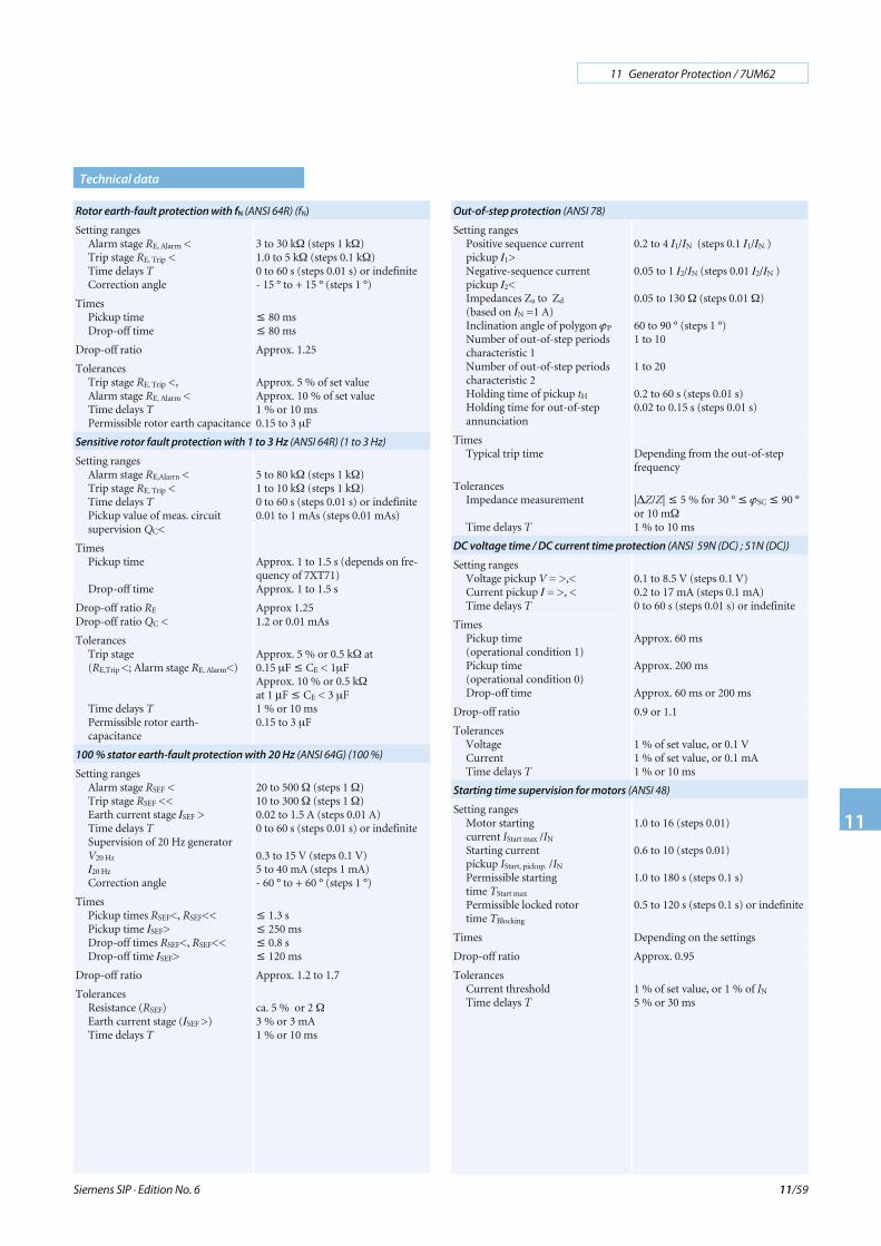
Siemens SIP · Edition No. 6
11 Generator Protection / 7UM62
11
11/59
Rotor earth-fault protection with fN (ANSI 64R) (fN)
Setting rangesAlarm stage RE, Alarrn <Trip stage RE, Trip <Time delays TCorrection angle
3 to 30 kΩ (steps 1 kΩ)1.0 to 5 kΩ (steps 0.1 kΩ)0 to 60 s (steps 0.01 s) or indefinite- 15 ° to + 15 ° (steps 1 °)
TimesPickup timeDrop-off time
≤ 80 ms≤ 80 ms
Drop-off ratio Approx. 1.25
TolerancesTrip stage RE, Trip <,Alarm stage RE, Alarm <Time delays TPermissible rotor earth capacitance
Approx. 5 % of set valueApprox. 10 % of set value1 % or 10 ms0.15 to 3 μF
Sensitive rotor fault protection with 1 to 3 Hz (ANSI 64R) (1 to 3 Hz)
Setting rangesAlarm stage RE,Alarrn <Trip stage RE, Trip <Time delays TPickup value of meas. circuitsupervision QC<
5 to 80 kΩ (steps 1 kΩ)1 to 10 kΩ (steps 1 kΩ)0 to 60 s (steps 0.01 s) or indefinite0.01 to 1 mAs (steps 0.01 mAs)
TimesPickup time
Drop-off time
Approx. 1 to 1.5 s (depends on fre-quency of 7XT71)Approx. 1 to 1.5 s
Drop-off ratio RE
Drop-off ratio QC <Approx 1.251.2 or 0.01 mAs
TolerancesTrip stage(RE,Trip <; Alarm stage RE, Alarm<)
Time delays TPermissible rotor earth-capacitance
Approx. 5 % or 0.5 kΩ at0.15 μF ≤ CE < 1μFApprox. 10 % or 0.5 kΩat 1 μF ≤ CE < 3 μF1 % or 10 ms0.15 to 3 μF
100 % stator earth-fault protection with 20 Hz (ANSI 64G) (100 %)
Setting rangesAlarm stage RSEF <Trip stage RSEF <<Earth current stage ISEF >Time delays TSupervision of 20 Hz generatorV20 Hz
I20 Hz
Correction angle
20 to 500 Ω (steps 1 Ω)10 to 300 Ω (steps 1 Ω)0.02 to 1.5 A (steps 0.01 A)0 to 60 s (steps 0.01 s) or indefinite
0.3 to 15 V (steps 0.1 V)5 to 40 mA (steps 1 mA)- 60 ° to + 60 ° (steps 1 °)
TimesPickup times RSEF<, RSEF<<Pickup time ISEF>Drop-off times RSEF<, RSEF<<Drop-off time ISEF>
≤ 1.3 s≤ 250 ms≤ 0.8 s≤ 120 ms
Drop-off ratio Approx. 1.2 to 1.7
TolerancesResistance (RSEF)Earth current stage (ISEF >)Time delays T
ca. 5 % or 2 Ω3 % or 3 mA1 % or 10 ms
Out-of-step protection (ANSI 78)
Setting rangesPositive sequence currentpickup I1>Negative-sequence currentpickup I2<Impedances Za to Zd
(based on IN =1 A)Inclination angle of polygon ϕP
Number of out-of-step periodscharacteristic 1Number of out-of-step periodscharacteristic 2Holding time of pickup tH
Holding time for out-of-stepannunciation
0.2 to 4 I1/IN (steps 0.1 I1/IN )
0.05 to 1 I2/IN (steps 0.01 I2/IN )
0.05 to 130 Ω (steps 0.01 Ω)
60 to 90 ° (steps 1 °)1 to 10
1 to 20
0.2 to 60 s (steps 0.01 s)0.02 to 0.15 s (steps 0.01 s)
TimesTypical trip time Depending from the out-of-step
frequency
TolerancesImpedance measurement
Time delays T
|ΔZ/Z| ≤ 5 % for 30 ° ≤ ϕSC ≤ 90 °or 10 mΩ1 % to 10 ms
DC voltage time / DC current time protection (ANSI 59N (DC) ; 51N (DC))
Setting rangesVoltage pickup V = >,<Current pickup I = >, <Time delays T
0.1 to 8.5 V (steps 0.1 V)0.2 to 17 mA (steps 0.1 mA)0 to 60 s (steps 0.01 s) or indefinite
TimesPickup time(operational condition 1)Pickup time(operational condition 0)Drop-off time
Approx. 60 ms
Approx. 200 ms
Approx. 60 ms or 200 ms
Drop-off ratio 0.9 or 1.1
TolerancesVoltageCurrentTime delays T
1 % of set value, or 0.1 V1 % of set value, or 0.1 mA1 % or 10 ms
Starting time supervision for motors (ANSI 48)
Setting rangesMotor startingcurrent IStart max /IN
Starting currentpickup IStart, pickup. /IN
Permissible startingtime TStart max
Permissible locked rotortime TBlocking
1.0 to 16 (steps 0.01)
0.6 to 10 (steps 0.01)
1.0 to 180 s (steps 0.1 s)
0.5 to 120 s (steps 0.1 s) or indefinite
Times Depending on the settings
Drop-off ratio Approx. 0.95
TolerancesCurrent thresholdTime delays T
1 % of set value, or 1 % of IN
5 % or 30 ms
Technical data
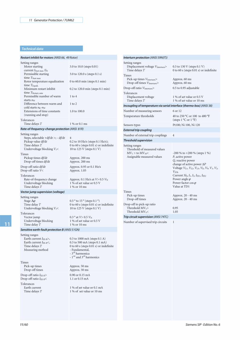
Siemens SIP · Edition No. 6
11 Generator Protection / 7UM62
11
11/60
Restart inhibit for motors (ANSI 66, 49 Rotor)
Setting rangesMotor startingcurrent IStart max /IN
Permissible startingtime TStart max
Rotor temperature equalizationtime TEquali.
Minimum restart inhibittime TRestart, min
Permissible number of warmstarts nW
Difference between warm andcold starts nK-nW
Extensions of time constants(running and stop)
3.0 to 10.0 (steps 0.01)
3.0 to 120.0 s (steps 0.1 s)
0 to 60.0 min (steps 0.1 min)
0.2 to 120.0 min (steps 0.1 min)
1 to 4
1 to 2
1.0 to 100.0
TolerancesTime delays T 1 % or 0.1 ms
Rate-of-frequency-change protection (ANSI 81R)
Setting rangesSteps, selectable +df/dt >; - df/dtPickup value df/dtTime delays TUndervoltage blocking V1<
40.2 to 10 Hz/s (steps 0.1 Hz/s);0 to 60 s (steps 0.01 s) or indefinite10 to 125 V (steps 0.1 V)
TimesPickup times df/dtDrop-off times df/dt
Approx. 200 msApprox. 200 ms
Drop-off ratio df/dtDrop-off ratio V<
Approx. 0.95 or 0.1 Hz/sApprox. 1.05
TolerancesRate-of-frequency changeUndervoltage blockingTime delays T
Approx. 0.1 Hz/s at V> 0.5 VN
1 % of set value or 0.5 V1 % or 10 ms
Vector jump supervision (voltage)
Setting rangesStage ΔϕTime delay TUndervoltage blocking V1<
0.5 ° to 15 ° (steps 0.1 °)0 to 60 s (steps 0.01 s) or indefinite10 to 125 V (steps 0.1 V)
TolerancesVector jumpUndervoltage blockingTime delay T
0.3 ° at V> 0.5 VN
1 % of set value or 0.5 V1 % or 10 ms
Sensitive earth-fault protection B (ANSI 51GN)
Setting rangesEarth current IEE-B>,Earth current IEE-B<,Time delays TMeasuring method
0.3 to 1000 mA (steps 0.1 A)0.3 to 500 mA (steps 0.1 mA)0 to 60 s (steps 0.01 s) or indefinite- Fundamental,- 3rd harmonica- 1rst and 3rd harmonics
TimesPick-up timesDrop-off times
Approx. 50 msApprox. 50 ms
Drop-off ratio IEE-B>Drop-off ratio IEE-B<
0.90 or 0.15 mA1.1 or 0.15 mA
TolerancesEarth currentTime delays T
1 % of set value or 0.1 mA1 % of set value or 10 ms
Technical data
Interturn protection (ANSI 59N(IT))
Setting rangesDisplacement voltage VInterturn>Time delays T
0.3 to 130 V (steps 0.1 V)0 to 60 s (steps 0.01 s) or indefinite
TimesPick-up times VInterturn>Drop-off times VInterturn>
Approx. 60 msApprox. 60 ms
Drop-off ratio VInterturn> 0.5 to 0.95 adjustable
TolerancesDisplacement voltageTime delays T
1 % of set value or 0.5 V1 % of set value or 10 ms
Incoupling of temperature via serial interface (thermo-box) (ANSI 38)
Number of measuring sensors 6 or 12
Temperature thresholds 40 to 250 °C or 100 to 480 °F(steps 1 °C or 1 °F)
Sensors types Pt100; Ni 100, Ni 120
External trip coupling
Number of external trip couplings 4
Threshold supervision
Setting rangesThreshold of measured valuesMV1 > to MV10<Assignable measured values
-200 % to +200 % (steps 1 %)P, active powerQ, reactive powerchange of active power ΔPVoltage VL1, VL2, VL3, VE, V0, V1, V2,VE3h
Current 3I0, I1, I2, IEE1, IEE2
Power angle ϕPower factor cos ϕValue at TD1
TimesPick-up timesDrop-off times
Approx. 20 - 40 msApprox. 20 - 40 ms
Drop-off to pick-up ratioThreshold MVx>Threshold MVx<
0.951.05
Trip circuit supervision (ANSI 74TC)
Number of supervised trip circuits 1
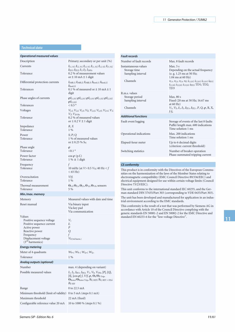
Siemens SIP · Edition No. 6
11 Generator Protection / 7UM62
11
11/61
Fault records
Number of fault records Max. 8 fault records
Instantaneous valuesStorage timeSampling interval
Channels
Max. 5 sDepending on the actual frequency(e. g. 1.25 ms at 50 Hz;1.04 ms at 60 Hz)vL1, vL2, vL3, vE; iL1,S1; iL2,S1; iL3,S1; iEE1;iL1,S2; iL2,S2; iL3,S2; iEE2; TD1; TD2;TD3
R.m.s. valuesStorage periodSampling interval
Channels
Max. 80 sFixed (20 ms at 50 Hz; 16.67 msat 60 Hz)V1, VE, I1, I2, IEE1, IEE2 , P, Q, ϕ, R, X,f-fn
Additional functions
Fault event logging Storage of events of the last 8 faultsPuffer length max. 600 indicationsTime solution 1 ms
Operational indications Max. 200 indicationsTime solution 1 ms
Elapsed-hour meter Up to 6 decimal digits(criterion: current threshold)
Switching statistics Number of breaker operationPhase-summated tripping current
CE conformity
This product is in conformity with the Directives of the European Commu-nities on the harmonization of the laws of the Member States relating toelectromagnetic compatibility (EMC Council Directive 89/336/EEC) andelectrical equipment designed for use within certain voltage limits (CouncilDirective 73/23/EEC).
This unit conforms to the international standard IEC 60255, and the Ger-man standard DIN 57435/Part 303 (corresponding to VDE 0435/Part 303).
The unit has been developed and manufactured for application in an indus-trial environment according to the EMC standards.
This conformity is the result of a test that was performed by Siemens AG inaccordance with Article 10 of the Council Directive complying with thegeneric standards EN 50081-2 and EN 50082-2 for the EMC Directive andstandard EN 60255-6 for the “low-voltage Directive”.
Technical data
Operational measured values
Description Primary; secondary or per unit (%)
Currents
Tolerance
IL1, S1; IL2, S1; IL3, S1; IL1, S2; IL2, S2; IL3, S2;IEE1; IEE2; I1; I2; I20Hz
0.2 % of measurement valuesor ± 10 mA ± 1 digit
Differential protection currents
Tolerances
IDiffL1; IDiffL2; IDiffL3; IRestL1; IRestL2;IRestL3;0.1 % of measured or ± 10 mA ± 1digit
Phase angles of currents
Tolerances
ϕIL1,S1; ϕIL2,S1; ϕIL3,S1; ϕIL1,S2; ϕIL2,S2;ϕIL3,S2;< 0.5 °
Voltages
Tolerance
VL1; VL2; VL3; VE; VL12; VL23; VL31; V1;V2; V20 Hz
0.2 % of measured valuesor ± 0.2 V ± 1 digit
ImpedanceTolerance
R, X1 %
PowerTolerance
S; P; Q1 % of measured valuesor ± 0.25 % SN
Phase angleTolerance
ϕ<0.1 °
Power factorTolerance
cos ϕ (p.f.)1 % ± 1 digit
FrequencyTolerance
f10 mHz (at V> 0.5 VN; 40 Hz < f< 65 Hz)
OverexcitationTolerance
V/f;1 %
Thermal measurementTolerance
ΘL1; ΘL2, ΘL3, Θ I2, ΘV/f, sensors5 %
Min./max. memory
Memory Measured values with date and time
Reset manual Via binary inputVia key padVia communication
ValuesPositive sequence voltagePositive sequence currentActive powerReactive powerFrequencyDisplacement voltage(3rd harmonics)
V1
I1
PQfVE(3rd harm.)
Energy metering
Meter of 4 quadrants WP+; WP–; WQ+; WQ–
Tolerance 1 %
Analog outputs (optional)
Number max. 4 (depending on variant)
Possible measured values I1, I2, IEE1, IEE2, V1, V0, V03h, |P|, |Q|,|S|, |cos ϕ| f, V/f, ϕ, ΘS/ΘS Trip,ΘRotor/ΘRotor Trip, RE, REF; RE, REF 1-3Hz;RE SEF
Range 0 to 22.5 mA
Minimum threshold (limit of validity) 0 to 5 mA (steps 0.1 mA)
Maximum threshold 22 mA (fixed)
Configurable reference value 20 mA 10 to 1000 % (steps 0.1 %)
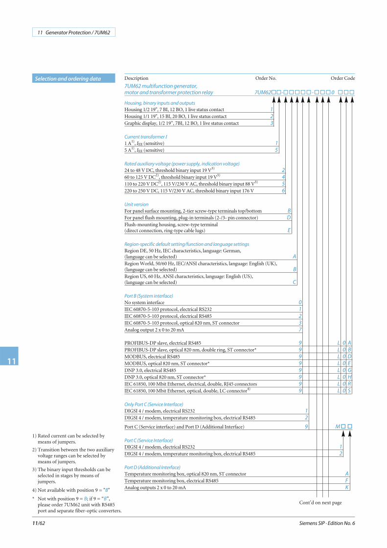
Siemens SIP · Edition No. 6
11 Generator Protection / 7UM62
11
11/62
Selection and ordering data Description Order No. Order Code
7UM62 multifunction generator,
motor and transformer protection relay 7UM62��-�����-���0 ���
Housing, binary inputs and outputs
Housing 1/2 19", 7 BI, 12 BO, 1 live status contact 1
Housing 1/1 19", 15 BI, 20 BO, 1 live status contact 2
Graphic display, 1/2 19'', 7BI, 12 BO, 1 live status contact 3
Current transformer IN
1 A1), IEE (sensitive) 1
5 A1), IEE (sensitive) 5
Rated auxiliary voltage (power supply, indication voltage)
24 to 48 V DC, threshold binary input 19 V3)2
60 to 125 V DC2), threshold binary input 19 V3)4
110 to 220 V DC2), 115 V/230 V AC, threshold binary input 88 V3)5
220 to 250 V DC, 115 V/230 V AC, threshold binary input 176 V 6
Unit version
For panel surface mounting, 2-tier screw-type terminals top/bottom B
For panel flush mounting, plug-in terminals (2-/3- pin connector) D
Flush-mounting housing, screw-type terminal(direct connection, ring-type cable lugs) E
Region-specific default setting/function and language settings
Region DE, 50 Hz, IEC characteristics, language: German,(language can be selected) A
Region World, 50/60 Hz, IEC/ANSI characteristics, language: English (UK),(language can be selected) B
Region US, 60 Hz, ANSI characteristics, language: English (US),(language can be selected) C
Port B (System interface)
No system interface 0
IEC 60870-5-103 protocol, electrical RS232 1
IEC 60870-5-103 protocol, electrical RS485 2
IEC 60870-5-103 protocol, optical 820 nm, ST connector 3
Analog output 2 x 0 to 20 mA 7
PROFIBUS-DP slave, electrical RS485 9 L 0 A
PROFIBUS-DP slave, optical 820 nm, double ring, ST connector* 9 L 0 B
MODBUS, electrical RS485 9 L 0 D
MODBUS, optical 820 nm, ST connector* 9 L 0 E
DNP 3.0, electrical RS485 9 L 0 G
DNP 3.0, optical 820 nm, ST connector* 9 L 0 H
IEC 61850, 100 Mbit Ethernet, electrical, double, RJ45 connectors 9 L 0 R
IEC 61850, 100 Mbit Ethernet, optical, double, LC connector4)9 L 0 S
Only Port C (Service Interface)
DIGSI 4 / modem, electrical RS232 1
DIGSI 4 / modem, temperature monitoring box, electrical RS485 2
Port C (Service interface) and Port D (Additional Interface) 9 M��
Port C (Service Interface)
DIGSI 4 / modem, electrical RS232 1
DIGSI 4 / modem, temperature monitoring box, electrical RS485 2
Port D (Additional Interface)
Temperature monitoring box, optical 820 nm, ST connector A
Temperature monitoring box, electrical RS485 F
Analog outputs 2 x 0 to 20 mA K
Cont’d on next page
1) Rated current can be selected bymeans of jumpers.
2) Transition between the two auxiliaryvoltage ranges can be selected bymeans of jumpers.
3) The binary input thresholds can beselected in stages by means ofjumpers.
4) Not available with position 9 = "B"
* Not with position 9 = B; if 9 = “B”,please order 7UM62 unit with RS485port and separate fiber-optic converters.
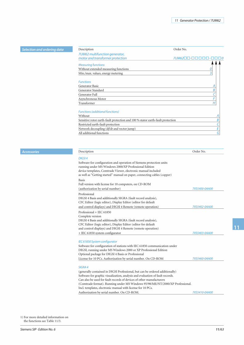
Siemens SIP · Edition No. 6
11 Generator Protection / 7UM62
11
11/63
Selection and ordering data
Description Order No.
DIGSI 4
Software for configuration and operation of Siemens protection unitsrunning under MS Windows 2000/XP Professional Editiondevice templates, Comtrade Viewer, electronic manual includedas well as “Getting started” manual on paper, connecting cables (copper)
BasisFull version with license for 10 computers, on CD-ROM
(authorization by serial number) 7XS5400-0AA00
ProfessionalDIGSI 4 Basis and additionally SIGRA (fault record analysis),CFC Editor (logic editor), Display Editor (editor for default
and control displays) and DIGSI 4 Remote (remote operation) 7XS5402-0AA00
Professional + IEC 61850Complete versionDIGSI 4 Basis and additionally SIGRA (fault record analysis),CFC Editor (logic editor), Display Editor (editor for defaultand control displays) and DIGSI 4 Remote (remote operation)
+ IEC 61850 system configurator 7XS5403-0AA00
IEC 61850 System configurator
Software for configuration of stations with IEC 61850 communication underDIGSI, running under MS Windows 2000 or XP Professional EditionOptional package for DIGSI 4 Basis or Professional
License for 10 PCs. Authorization by serial number. On CD-ROM 7XS5460-0AA00
SIGRA 4
(generally contained in DIGSI Professional, but can be ordered additionally)Software for graphic visualization, analysis and evaluation of fault records.Can also be used for fault records of devices of other manufacturers(Comtrade format). Running under MS Windows 95/98/ME/NT/2000/XP Professional.Incl. templates, electronic manual with license for 10 PCs.
Authorization by serial number. On CD-ROM. 7XS5410-0AA00
Description Order No.
7UM62 multifunction generator,
motor and transformer protection 7UM62��-�����-���0
Measuring functions
Without extended measuring functions 0
Min./max. values, energy metering 3
Functions1)
Generator Basic A
Generator Standard B
Generator Full C
Asynchronous Motor F
Transformer H
Functions (additional functions) 1)
Without A
Sensitive rotor earth-fault protection and 100 % stator earth-fault protection B
Restricted earth-fault protection C
Network decoupling (df/dt and vector jump) E
All additional functions G
1) For more detailed information onthe functions see Table 11/3.
Accessories
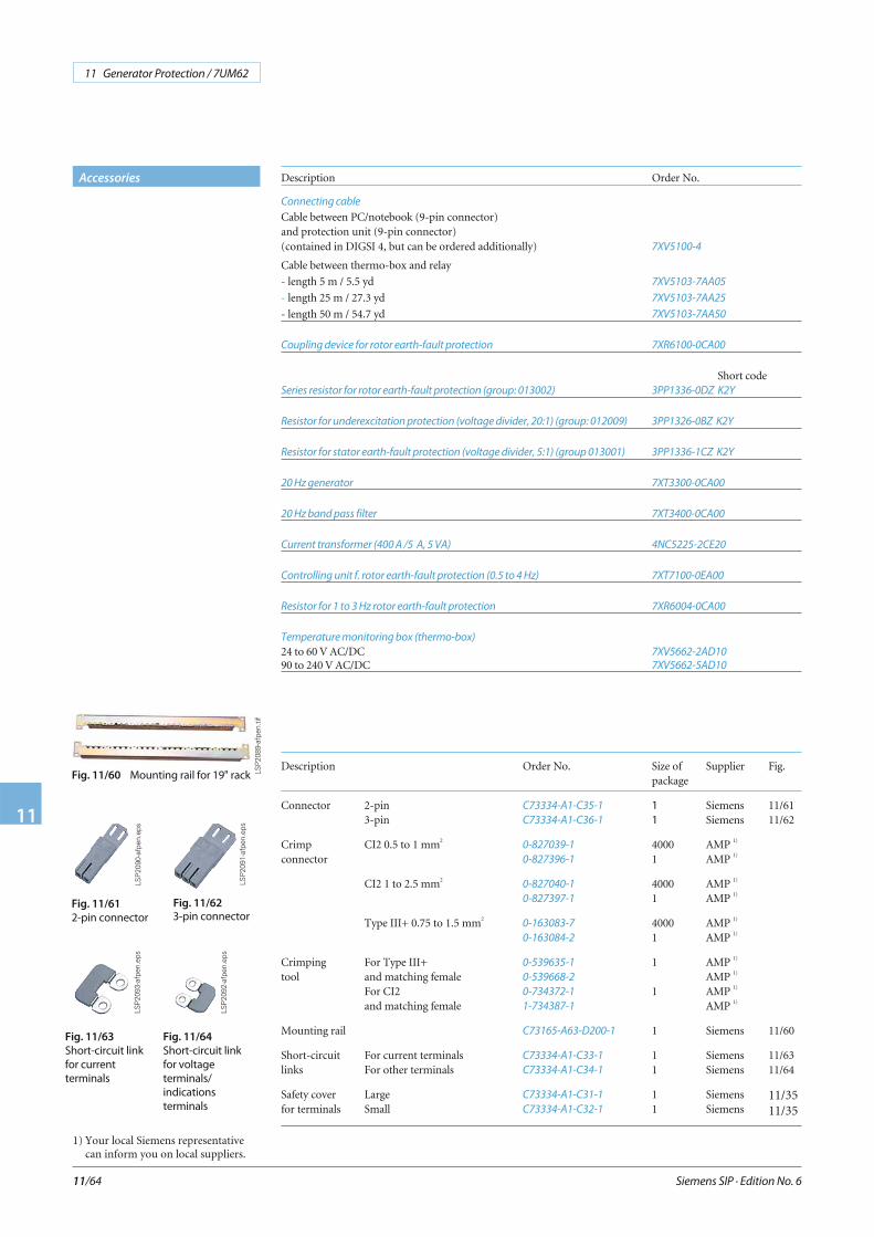
Siemens SIP · Edition No. 6
11 Generator Protection / 7UM62
11
11/64
Fig. 11/60 Mounting rail for 19" rack
Fig. 11/63
Short-circuit link
for current
terminals
Fig. 11/64
Short-circuit link
for voltage
terminals/
indications
terminals
LSP
2089
-afp
en.ti
f
LSP
2093
-afp
en.e
ps
LSP
2092
-afp
en.e
ps
Accessories
Fig. 11/61
2-pin connector
Fig. 11/62
3-pin connector
LSP
2090
-afp
en.e
ps
LSP
2091
-afp
en.e
ps
Description Order No. Size ofpackage
Supplier Fig.
Connector 2-pin3-pin
C73334-A1-C35-1
C73334-A1-C36-1
11
SiemensSiemens
11/6111/62
Crimp CI2 0.5 to 1 mm2
connector0-827039-1
0-827396-1
40001
AMP 1)
AMP 1)
CI2 1 to 2.5 mm20-827040-1
0-827397-1
40001
AMP 1)
AMP 1)
Type III+ 0.75 to 1.5 mm20-163083-7
0-163084-2
40001
AMP 1)
AMP 1)
Crimping For Type III+tool and matching female
For CI2and matching female
0-539635-1
0-539668-2
0-734372-1
1-734387-1
1
1
AMP 1)
AMP 1)
AMP 1)
AMP 1)
Mounting rail C73165-A63-D200-1 1 Siemens 11/60
Short-circuit For current terminalslinks For other terminals
C73334-A1-C33-1
C73334-A1-C34-1
11
SiemensSiemens
11/6311/64
Safety cover Largefor terminals Small
C73334-A1-C31-1
C73334-A1-C32-1
11
SiemensSiemens
11/3511/35
Description Order No.
Connecting cable
Cable between PC/notebook (9-pin connector)and protection unit (9-pin connector)(contained in DIGSI 4, but can be ordered additionally) 7XV5100-4
Cable between thermo-box and relay
- length 5 m / 5.5 yd 7XV5103-7AA05
- length 25 m / 27.3 yd 7XV5103-7AA25
- length 50 m / 54.7 yd 7XV5103-7AA50
Coupling device for rotor earth-fault protection 7XR6100-0CA00
Short codeSeries resistor for rotor earth-fault protection (group: 013002) 3PP1336-0DZ K2Y
Resistor for underexcitation protection (voltage divider, 20:1) (group: 012009) 3PP1326-0BZ K2Y
Resistor for stator earth-fault protection (voltage divider, 5:1) (group 013001) 3PP1336-1CZ K2Y
20 Hz generator 7XT3300-0CA00
20 Hz band pass filter 7XT3400-0CA00
Current transformer (400 A /5 A, 5 VA) 4NC5225-2CE20
Controlling unit f. rotor earth-fault protection (0.5 to 4 Hz) 7XT7100-0EA00
Resistor for 1 to 3 Hz rotor earth-fault protection 7XR6004-0CA00
Temperature monitoring box (thermo-box)
24 to 60 V AC/DC 7XV5662-2AD10
90 to 240 V AC/DC 7XV5662-5AD10
1) Your local Siemens representativecan inform you on local suppliers.
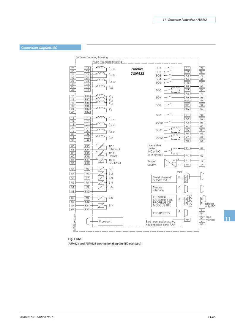
Siemens SIP · Edition No. 6
11 Generator Protection / 7UM62
11
11/65
Connection diagram, IEC
Fig. 11/65
7UM621 and 7UM623 connection diagram (IEC standard)
7UM623
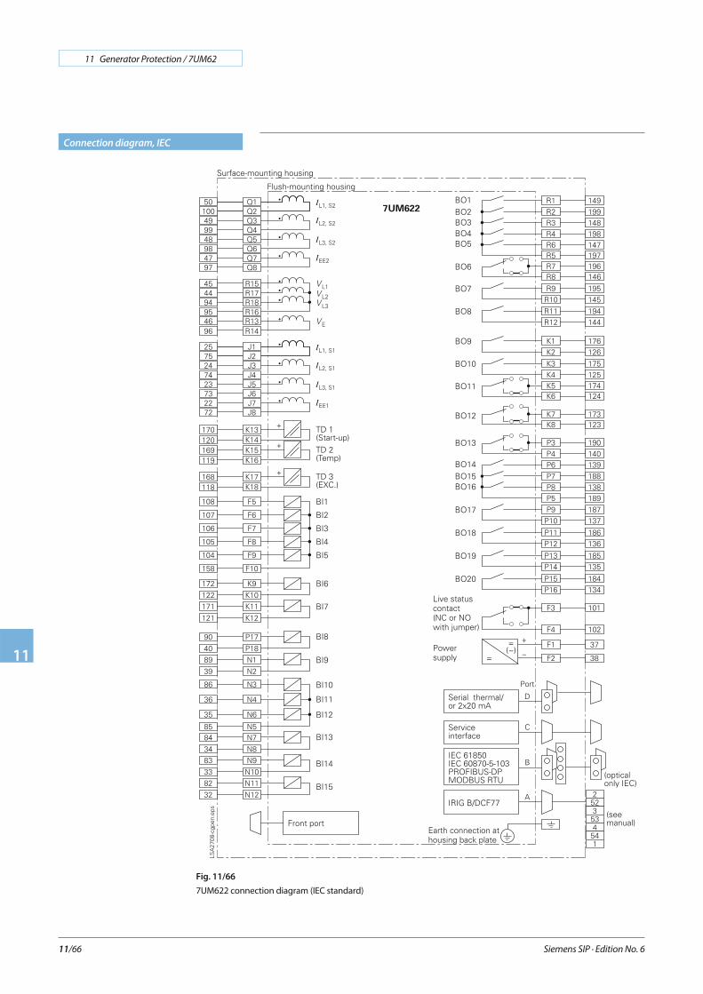
Siemens SIP · Edition No. 6
11 Generator Protection / 7UM62
11
11/66
Connection diagram, IEC
Fig. 11/66
7UM622 connection diagram (IEC standard)

Siemens SIP · Edition No. 6
11 Generator Protection / 7UM62
11
11/67
Connection diagram, ANSI
Fig. 11/67
7UM621 and 7UM623 connection diagram (ANSI standard)
7UM623
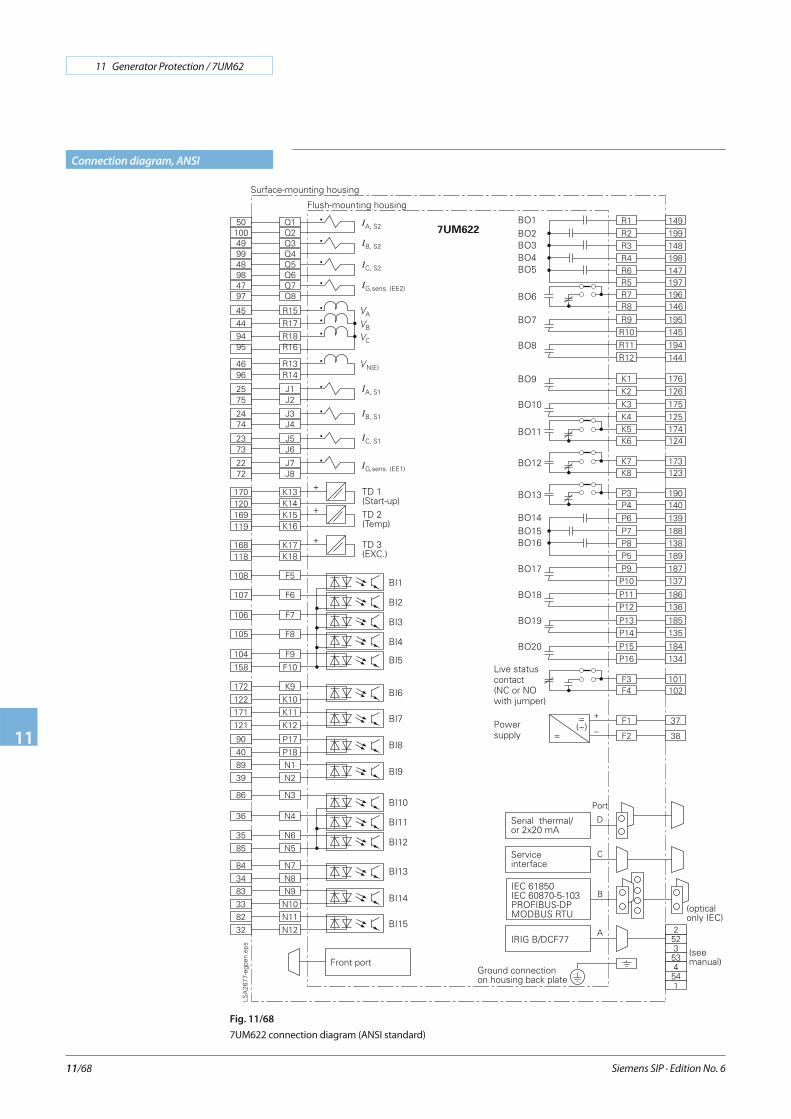
Siemens SIP · Edition No. 6
11 Generator Protection / 7UM62
11
11/68
Connection diagram, ANSI
Fig. 11/68
7UM622 connection diagram (ANSI standard)