Embed Size (px)
Citation preview

1

2

3
INTRODUCTION / TABLE OF CONTENTS Step One
The general purpose indicator displays tank level or volume in engineering units with 1‐4 relay status indicators, and is compatible with any LVCN‐414, LVCN‐210 & LVCN‐318 Series level sensor that's been configured with LVCN‐414‐SW 6.0 software and updated to V50 firmware or higher. Powered by the LVCN‐414, LVCN‐210 & LVCN‐318 Series sensor, the field mount indicator may be located up to 4.5m (15') from the sensor. LVCN‐40 Series requires no programming. The indicator repeats the measured value, applicable relay status and set point configuration of the attached sensor. If the level sensor’s relay set points require changing, they can be easily made through the field indicator. Table of Contents Specifications: ......................................................................................................................................................... 4 Dimensions: ......................................................................................................................................................... 4 Components: .............................................................................................................................................. 4 Safety Precautions: ................................................................................................................................................ 5 Getting Started: ...................................................................................................................................................... 6 Wiring: ......................................................................................................................................................... 7 Adding a Loop Powered Display: ............................................................................................................... 7 Understanding LVCN‐414, LVCN‐210 & LVCN‐318 Series sensors: ....................................................................... 8 Liquid Height vs. Volume: .......................................................................................................................... 8 Linear vs. Non‐Linear: ................................................................................................................................ 9 Example #1 (Volume Output): ....................................................................................................... 9 Example #2 (Current Output): ..................................................................................................... 10 Relay Settings: ......................................................................................................................................... 11 Installation: ....................................................................................................................................................... 12 LVCN‐40 Series Getting Around: .......................................................................................................................... 13 Menu: ....................................................................................................................................................... 13 Changing a Pump Set Point: ..................................................................................................................... 14 Changing an Alarm Set Point: .................................................................................................................. 15 Troubleshooting .................................................................................................................................................... 16 Display Descriptors: .................................................................................................................................. 16

4
SPECIFICATIONS / DIMENSIONS Step Two
Display type: LCD, 6‐digit with 4 relay indicators
Display units: Engineering units, liquid volume or height
Display output: ‐9999.9 to 99999.9 Character height: 0.374" (9.5 mm) Decimal point: Fixed Dot indication: Relay status User interface: Three button Sensor input: Any LVCN‐414, LVCN‐210 &
LVCN‐318 Series sensor
Supply voltage: Provided by the level sensor Operating temp.: F: ‐4° to 140° C: ‐20° to 60° Cable type: 4‐conductor, #22 AWG Cable length: 4' (1.2m) Cable material: Polyurethane Enclosure rating: NEMA 4 (IP65) when mounted Enclosure mat’l: Polycarbonate Enclosure type: Panel mount Button mat’l: Silicon rubber Compliance: CE, RoHS
Dimensions
Included Components LVCN‐40 Series comes with a 4’ (1.2m) cable, locking nut and the Manual.
LVCN‐40 Series Front View LVCN‐40 Series Side View

5
SAFETY PRECAUTIONS Step Three
About this Manual: PLEASE READ THE ENTIRE MANUAL PRIOR TO INSTALLING OR USING THIS PRODUCT.
This manual includes information on the LVCN‐40 Series level indicator from OMEGA ENGINEERING. Please
refer to the part number located on the switch label to verify the exact model configuration, which you have
purchased.
User’s Responsibility for Safety: OMEGA ENGINEERING manufactures a broad range of level sensing
technologies. While each of these sensors is designed to operate in a wide variety of applications, it is the user’s
responsibility to select a sensor model that is appropriate for the application, install it properly, perform tests of
the installed system, and maintain all components. The failure to do so could result in property damage or
serious injury.
Proper Installation and Handling: Only professional staff should install and/or repair this product. Install
the level indicator with the included locking nut and never over tighten the indicator within the installation.
Always check for leaks prior to system start‐up.
Wiring and Electrical: A supply voltage of 12 to 28 VDC is used to power the LVCN‐40 Series and the LVCN‐
414, LVCN‐210 & LVCN‐318 Series sensor. Electrical wiring of the transmitter should be performed in accordance
with all applicable national, state, and local codes.
Material Compatibility: The enclosure is made of Polycarbonate (PC) with the Cable made of
Polyurethane and the Buttons made of silicon rubber. Make sure that the model, which you have selected, is
chemically compatible with the application media.
Enclosure: While the level indicator housing is liquid‐resistant the LVCN‐40 Series is not designed to be
operational when immersed. It should be mounted in such a way that the enclosure and level indicator do not
come into contact with the application media under normal operational conditions.
Make a Fail‐Safe System: Design a fail‐safe system that accommodates the possibility of LVCN‐414, LVCN‐
210 & LVCN‐318 Series/LVCN‐40 Series and/or power failure. OMEGA ENGINEERING recommends the use of
redundant backup systems and alarms in addition to the primary system.
Flammable, Explosive or Hazardous Applications: LVCN‐40 Series should not be used within classified
hazardous environments.
Safety
Installation should be done by properly trained staff
Supply voltage should never exceed a maximum of 28 VDC
Make sure the sensor is chemically compatible with your application
Design a fail‐safe system that accommodates the possibility of sensor and/or power failure
This sensor should not be used in classified hazardous environments

6
GETTING STARTED Step Four
LVCN‐40 Series does not require any configuration. LVCN‐40 Series level indicator will automatically read the
configuration of the attached LVCN‐414, LVCN‐210 & LVCN‐318 Series sensor and display the level per the
sensor’s configuration. The sensor does require configuration with the LVCN‐414‐SW 6.0 software (especially
if any relays are to be used). For a copy of the LVCN‐414‐SW 6.0 software, please go to
http://www.Omega.com/ftp, click on the Flow, Level, pH, Environmental, and Pressure Section, select
Products and then click on the LVCN414 folder. Before attaching LVCN‐40 Series to any sensor, configure the
LVCN‐414, LVCN‐210 & LVCN‐318 Series sensor to LVCN‐414‐SW 6.0 software via the Fob. Once the sensor is
configured, remove the Fob and attach the LVCN‐40 Series.
Note: Please refer to LVCN‐414, LVCN‐210 & LVCN‐318 Series manual for the wiring, configuration with the LVCN‐414‐SW 6.0 software and installation of the sensor.

7
WIRING Step Five
Wiring LVCN‐40 Series to any LVCN‐414, LVCN‐210 & LVCN‐318 Series Sensor: LVCN‐40 Series and associated
level sensor require a 12 to 28 VDC power supply to operate. The maximum cable distance between LVCN‐40
Series and the sensor is 15’ (4.5m). Follow the below steps to wire LVCN‐40 series with the sensor:
Sensor
LVCN‐40 Series
Wiring identical for all series of LVCN‐414, LVCN‐210 & LVCN‐318 Series Sensors.
Use only the Red, Black, Green and White wires.
1. Connect the Red and Black wires of both LVCN‐40 Series and the sensor to the 12‐28 VDC power supply.
2. Connect the Green and White wires of LVCN‐40 Series to the corresponding Green and White wires of the sensor.
3. Isolate the Green and White wires from active power to prevent a short of the configuration circuit.
Adding a Loop Powered Display
General Safety
Where personal safety or significant property damage can occur due to a spill, the application must
have a redundant backup safety system installed.
Wiring should always be done by a licensed electrician.
Supply voltage should never exceed 28 VDC.
Protect the sensor from electrical spikes by isolating the power.
Design a fail‐safe system for possible indicator and/or power failure.
Never use the sensor in environments classified as Hazardous.

8
UNDERSTANDING LVCN‐40 SERIES Step Six
Level Height vs. Volume: The latest version of LVCN‐414‐SW 6.0 software has a new feature which allows the sensor to be configured to read either the height of the liquid or the volume of the liquid. This selection is made under the Sensor Output Units selection of either Volume (volume of liquid) or Distance (height of liquid). See the chart below for the engineering unit options available for both Distance and Volume.
Units of Measurement
Distance Volume
Inches Cm Feet
Meters
Gallons Liters
There are 6 different tank shapes that you can select with LVCN‐414‐SW 6.0 Software.
Vertical Cylinder Tank
Vertical Cylinder Tank with Cone Bottom
Rectangular Tank
Horizontal Cylinder Tank with End Caps
Horizontal Cylinder Tank with Spherical End Caps
Spherical Tank

9
UNDERSTANDING LVCN‐40 SERIES Step Six
Linear vs. Non‐Linear: Two of the shapes (Vertical Cylinder Tank and Rectangular Tank) will always provide a linear output, regardless of selecting Distance or Volume. The remaining four shapes (Vertical Cylinder Tank with Cone Bottom, Horizontal Cylinder Tank with End Caps, Horizontal Cylinder Tank with Spherical End Caps and Spherical Tank) will have a linear output when Distance is selected, but will have a non‐linear output when volume is selected.
Vertical Cylindrical Tank
In the above illustration, 10” of liquid will always be equal to 100 gallons of liquid (1” = 10 gallons).
Horizontal Cylinder Tank with End Caps
In the above illustration, 10” of liquid does not equal 100 gallons. The 10” at the bottom represents a rise of 62.8 gallons where the change between 10” and 20” represents an increase of 109.6 gallons.
When volume is selected, the 4‐20 mA output from the sensor will be proportional to the volume of the tank, not the height of the tank. This means that the current output will track the volume of the tank (in gallons or liters) within a non‐linear tank (Vertical Cylinder Tank with Cone Bottom, Horizontal Cylinder Tank with End Caps, Horizontal Cylinder Tank with Spherical End Caps or Spherical Tank).
When connecting the 4‐20 mA output to a display, the current signal will follow the volume of the tank. The display will also reflect the volume of the tank and not the height of the liquid.
Example #1 (Volume Output): In the illustrations above, @ 20” of liquid, the display will show 200.0 gallons in the Vertical Cylindrical Tank. However, in the Horizontal Cylinder Tank with End Caps, the same level of 20” would show 172.4 gallons.

10
UNDERSTANDING LVCN‐40 SERIES Step Six
Example #2 (Current Output): in the illustrations below, the 4mA signal is set at 0” (0.0 gallons) and the 20 mA signal is set to 60” (600.0 gallons). In the Vertical Cylindrical Tank, 40” of liquid will output a current signal of 14.67mA. However, in the Horizontal Cylindrical Tank with End Caps, 40” of liquid will output a current signal of 15.41mA. A simple loop display set with 4mA = 0 gallons and 20 mA = 600 gallons will show two different volumes based upon the tank shape configuration. Vertical Cylindrical Tank will show 400.0 gallons while Horizontal Cylindrical Tank with End Caps will show 428.0 gallons.
Vertical Cylindrical Tank
10” of liquid will always be equal to 100 gallons of liquid (1” = 10 gallons).
Horizontal Cylinder Tank with End Caps
1” of liquid does not equal 10 gallons. The 10” at the bottom represents a rise of 62.8 gallons where the change between 10” and 20” represents an increase of 109.6 gallons.

11
UNDERSTANDING LVCN‐40 SERIES Step Six
Relay Settings: LVCN‐40 Series not only displays the level reading of the LVCN‐414, LVCN‐210 & LVCN‐318 Series sensor (Height or Volume), but LVCN‐40 Series also allows you to adjust the settings for relays. LVCN‐40 Series will not allow changes to Sensor Height or Fill‐Height, just the relay settings.
The sensor configured to read inches of liquid plus 4 high alarm relays.
The sensor configured to read inches of liquid plus duplex relays and high and low alarm relays.
The sensor configured to read gallons of liquid plus 2 high alarm and 2 low relays.
The sensor configured to read gallons of liquid plus an auto empty relays and high and low alarm relays.

12
INSTALLATION Step Seven
LVCN‐40 Series is designed for typical panel mount installations, either located within an instrument panel or
through the wall of a NEMA box enclosure.
Panel Mount: The maximum cable distance between LVCN‐40 Series and LVCN‐414, LVCN‐210 & LVCN‐318
Series sensor is 15’ (4.5m). Follow the below steps to install the indicator in a panel or NEMA box enclosure
located near the sensor:
1. Drill (1) large 0.75” (19.1mm) diameter hole in the
panel for the cable and nipple.
2. Drill (1) small 0.25” (6.4mm) diameter hole 0.83”
(21.1mm) below the large hole that will prevent
the installed indicator from rotating off center.
3. Run the indicator cable through the large top hole
and locking nut (on the rear side of the panel).
4. Properly align the indicator with the flat gasket
and holes on the panel. Then press the indicator
in place against the panel.
5. Tighten the locking nut down over the nipple and route the cable for termination.
13
GETTING AROUND LVCN‐40 SERIES Step Eight
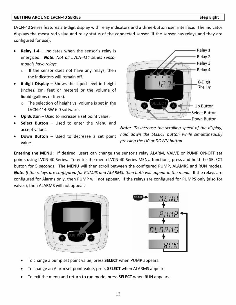
LVCN‐40 Series features a 6‐digit display with relay indicators and a three‐button user interface. The indicator
displays the measured value and relay status of the connected sensor (if the sensor has relays and they are
configured for use).
Relay 1‐4 – Indicates when the sensor’s relay is
energized. Note: Not all LVCN‐414 series sensor
models have relays.
o If the sensor does not have any relays, then
the indicators will remain off.
6‐digit Display – Shows the liquid level in height
(inches, cm, feet or meters) or the volume of
liquid (gallons or liters).
o The selection of height vs. volume is set in the
LVCN‐414‐SW 6.0 software.
Up Button – Used to increase a set point value.
Select Button – Used to enter the Menu and
accept values.
Down Button – Used to decrease a set point
value.
Note: To increase the scrolling speed of the display,
hold down the SELECT button while simultaneously
pressing the UP or DOWN button.
Entering the MENU: If desired, users can change the sensor’s relay ALARM, VALVE or PUMP ON‐OFF set
points using LVCN‐40 Series. To enter the menu LVCN‐40 Series MENU functions, press and hold the SELECT
button for 5 seconds. The MENU will then scroll between the configured PUMP, ALAMRS and RUN modes.
Note: If the relays are configured for PUMPS and ALARMS, then both will appear in the menu. If the relays are
configured for Alarms only, then PUMP will not appear. If the relays are configured for PUMPS only (also for
valves), then ALARMS will not appear.
To change a pump set point value, press SELECT when PUMP appears.
To change an Alarm set point value, press SELECT when ALARMS appear.
To exit the menu and return to run mode, press SELECT when RUN appears.

14
GETTING AROUND LVCN‐40 SERIES Step Eight
Changing a Pump Set Point: Sensors (LVCN‐414, LVCN‐210 & LVCN‐318 Series) with relays have (1‐4) channels
active on the LVCN‐40 Series. If after accessing the MENU, PUMP appears in the display, then at least (1) relay
is configured for pump or valve control. Simplex pump control has (1) ON and (1) OFF setting. Duplex pump
control (2‐pumps) has a third additional LAG setting. Note: Prior to making any changes, we recommend that
you write down all existing set point values. The example below highlights a duplex pump system in an
automatic empty or automatic fill operation with (1) LAG, (1) ON and (1) OFF set point. Use the following
steps to change your simplex or duplex pump control settings.
Automatic Empty Operation
Automatic Fill Operation
Steps to Change Pump Set Points
1. Hold SELECT for 5 seconds to enter the MENU. 2. Press SELECT when PUMP appears.
3. Press SELECT when the set point (ON, OFF, LAG) you want to change appears.
4. Press the UP and DOWN buttons to increase or decrease the set point to the desired value. To scroll faster, hold SELECT while pressing UP or DOWN.
5. To enter the set point, hold SELECT for 2 seconds.
6. To change another set point, press SELECT when the set point appears.
7. To exit the MENU, press SELECT when RUN appears.
Tech Tips
Never place a relay set point (ON, OFF, LAG) at the liquid empty or liquid full position. You should have at least some distance or volume buffer separating them. For example, in a 500 gallon tank, the relay set points could be placed at ≥ 10 gallons or ≤ 490 gallons.

15
GETTING AROUND LVCN‐40 SERIES Step Eight
Changing an Alarm Set Point: Sensors (LVCN‐414, LVCN‐210 & LVCN‐318 Series) with relays have (1‐4)
channels active on the LVCN‐40 Series. If after accessing the MENU, ALARMS appears in the display, then at
least (1) relay is configured as an alarm. The Alarm settings may be in any combination of LOW and/or HIGH
alarms (4‐HIGH, 1‐LOW & 3‐HIGH, 2‐LOW & 2‐HIGH, etc.). Note: Prior to making any changes, we recommend
that you write down all existing set point values. The example below highlights a 2‐LOW and 2‐HIGH alarm
operation with (4) set points. Use the following steps to change your alarm settings.
Steps to change Alarm settings:
1. Hold SELECT for 5 seconds to enter the MENU.
2. Press SELECT when ALARMS appears.
3. Press SELECT when the set point (HIGH2, HIGH 1, LOW1, LOW2) you want to change appears.
4. Press the UP and DOWN buttons to increase or decrease the set point to the desired value. To scroll faster, hold SELECT while pressing UP or DOWN.
5. To enter the set point, hold SELECT for 2 seconds.
6. To change another set point, press SELECT when the set point appears.
7. To exit the MENU, press SELECT when RUN appears.
Hints:
Never place a relays set point (High 1, Low 1) at the liquid empty or liquid full position. You should have at least some distance or volume buffer separating them. For example, in a 500 gallon tank, the relay set points could be placed at ≥ 10 gallons or ≤ 490 gallons.

16
TROUBLESHOOTING Step Nine
Display Descriptors: The following are the display’s operational descriptors, meaning and corrective action:
WARMUP WARMUP is seen when power is first applied to the sensor and LVCN‐40 Series. WARMUP indicates that the display is waiting for the sensor to acquire and send a valid level reading.
MENU Indicates the menu for configuration of relay set points.
PUMP PUMP is the identifier for the relay set points affecting Pump or Valve operations.
OFF OFF is the relay set point that turns OFF the pump.
ON ON is the relay set point that turns ON the pump.
LAG LAG is the set point that turns ON the lag pump.
ALARM Alarm is the identifier for the relay set points affecting Alarm operations.
HIGH # HIGH # is the relay set point that energizes a high alarm relay.
LOW # LOW # is the relay set point that energizes a low alarm relay.
CHECK WIRES Not All four wires are properly connected to the sensor. Check the wiring between the LVCN‐40 Series and the level sensor.
UPDATE FW REV The attached sensor is not running a version of the firmware (50.0 or higher) that is compatible with LVCN‐40 Series. Connect the LVCN‐414, LVCN‐210 or LVCN‐318 Series to the LVCN‐414‐SW 6.0 software and update the firmware.

17

18

19

20