Embed Size (px)
Citation preview

(Rev. 2.0_12-2015)
ISTRUZIONI PER LO SMONTAGGIO E RIMONTAGGIO POMPE BORA
SERIE 163÷1083
DISASSEMBLY AND REASSEMBLY INSTRUCTIONS FOR BORA PUMPS
163÷1083 SERIES
Istruzioni per lo smontaggio e rimontaggio pompe Bora / Disassembly and reassembly instruction for Bora pumps 2
INDICE
INDEX
ISTRUZIONE I SMONTAGGIO
POMPE BORA pag. 3 DISASSEMBLY INSTRUCTIONS
FOR BORA PUMPS
pag. 3
RIMOZIONE TENUTE A LABIRINTO
pag. 10 LABYRINTH SEAL REMOVAL
pag. 10
ISTRUZIONI DI SMONTAGGIO DELLA LANTERNA MOTORE DELLE POMPE SERIE HV
pag. 11 DISASSEMBLY INSTRUCTIONS OF THE MOTOR LANTERN FOR PUMPS SERIES HV
pag.11
ISTRUZIONI PER IL RIMONTAGGIO
DELLE POMPE BORA DOPO LA
MANUTENZIONE
pag. 14 REASSEMBLY INSTRUCTIONS FOR BORA PUMPS AFTER MAINTENANCE
pag. 14
Istruzioni per lo smontaggio e rimontaggio pompe Bora / Disassembly and reassembly instruction for Bora pumps 3
ISTRUZIONI PER LO SMONTAGGIO POMPE BORA
NOTA: nelle pagine seguenti vicino al nome dei compo-nenti delle pompe è indicato tra parentesi anche il numero di riferimento VDMA (che si trova nei disegni in sezione).
DISASSEMBLY INSTRUCTIONS FOR BORA PUMPS
NOTE: In the following pages, it is indicated in brackets the reference number VDMA of components (which are in the pump section drawings).
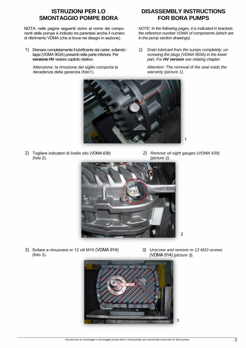
1) Drenare completamente il lubrificante dai carter, svitando i tappi (VDMA 903A) presenti nella parte inferiore. Per versione HV vedere capitolo relativo.
1) Drain lubricant from the sumps completely, un-screwing the plugs (VDMA 903A) in the lower part. For HV version see relating chapter.
Attenzione: la rimozione del sigillo comporta la decadenza della garanzia (foto1).
Attention: The removal of the seal voids the warranty (picture 1).
2) Togliere indicatori di livello olio (VDMA 639) (foto 2).
2) Remove oil sight gauges (VDMA 639) (picture 2).
3) Svitare e rimuovere nr 12 viti M10 (VDMA 914) (foto 3).
3) Unscrew and remove nr.12 M10 screws
(VDMA 914) (picture 3).
1
2
3

Istruzioni per lo smontaggio e rimontaggio pompe Bora / Disassembly and reassembly instruction for Bora pumps 4
4) Rimuovere carter lato comando (VDMA 166A). 4) Remove sump drive-end (VDMA 166A).
5) Rimuovere il cuscinetto a 1 corona di sfere (VDMA 320) dal carter con un estrattore cuscinetti.
5) Remove the single row ball bearing (VDMA 320) with a dedicated tool.
6) Versione HV: con apposite pinze rimuovere anello seeger per albero (VDMA 932) (foto 4).
6) HV Version: with dedicated pliers remove
the circlip for shaft (VDMA 932) (picture 4).
7) Togliere disco spandiolio (VDMA 657) e molle a tazza (VDMA 950) da albero trainante (VDMA 210A).
7) Remove the oil sprader (VDMA 657) and the
cup springs (VDMA 950) from driving shaft
(VDMA 210A).
8) Svitare la vite della rondella di spinta estremità albero trainato, utilizzare blocco di plastica per impedire rotazione del rotore (foto 5 - 6).
8) Unscrew the screw of the driving shaft end thrust washer, use a plastic block to prevent rotation of the rotors (picture 5 - 6).
4
5
6

Istruzioni per lo smontaggio e rimontaggio pompe Bora / Disassembly and reassembly instruction for Bora pumps 5
9) Dopo averle contrassegnate rimuovere spine coniche (VDMA 567) (foto 7); rimuovere nr 4 viti M10 dal fianco lato motore.
9) Mark and remove tapered pins (VDMA 567) (picture 7); remove nr.4 screws M10 from side cover drive-end.
10) Dotarsi di un attrezzo composto da nr 2 viti M10 x 180 mm (foto 8).
10) Take a tool consisting of nr 2 M10 x 180 mm screws (picture 8).
11) Avvitare le due viti M10 negli appositi fori
(foto 9). 11) Screw in the two M10 screws into the dedi-
cated holes (picture 9).
7
8
9
Nr. 4
Istruzioni per lo smontaggio e rimontaggio pompe Bora / Disassembly and reassembly instruction for Bora pumps 6
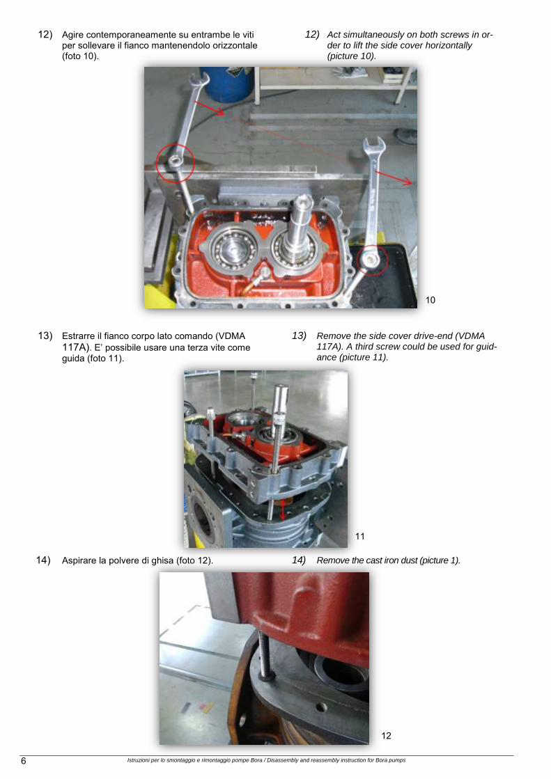
12) Agire contemporaneamente su entrambe le viti
per sollevare il fianco mantenendolo orizzontale (foto 10).
12) Act simultaneously on both screws in or-der to lift the side cover horizontally (picture 10).
13) Estrarre il fianco corpo lato comando (VDMA
117A). E’ possibile usare una terza vite come guida (foto 11).
13) Remove the side cover drive-end (VDMA 117A). A third screw could be used for guid-ance (picture 11).
14) Aspirare la polvere di ghisa (foto 12). 14) Remove the cast iron dust (picture 1).
10
11
12

Istruzioni per lo smontaggio e rimontaggio pompe Bora / Disassembly and reassembly instruction for Bora pumps 7
15) Togliere indicatori di livello olio (VDMA 639) da carter lato ingranaggi.
15) Remove oil sight gauge (VDMA 639) from sump non drive end.
16) Rimuovere disco spandiolio (VDMA 657) dal lato ingranaggi (foto 13).
16) Remove oil spreader (VDMA 657) from gear side (picture 13).
17) Contrassegnare fase ingranaggi e posizione
anelli calettamento (VDMA 930) (foto 14). 17) Mark the gear phase and locking element
position (VDMA 930) (picture 14).
18) Allentare nr 8 viti M6 da ogni calettatore e staccarlo.
18) Loosen nr 8 screws M6 from each locking Element and disassembly them.
19) Svitare nr 2 viti M12 e rimuovere i due ingranaggi (VDMA 870).
19) Unscrew nr 2 screws M12 and remove the two gears (VDMA 870).
20) Modelli 673÷1083: scalzare l'ingranaggio dai calettatori (VDMA 930) spingendolo verso la pompa (foto 15).
20) Models 673÷1083: undrmine the gear from locking elements (VDMA 930) by pushing it towards the pump (photo 15). (picture 15).
Fig. 12
13
14
15

Istruzioni per lo smontaggio e rimontaggio pompe Bora / Disassembly and reassembly instruction for Bora pumps 8
21) Con martello in plastica espellere rotori (VDMA 280) dai cuscinetti a due corone di sfere a contatto obliquo (VDMA 321) (foto 16).
21) Using a plastic mallet push out rotors shaft (VDMA 280) from double row angular contact ball bearing (VDMA 321) (picture 16).
22) Svitare nr 6 viti M8 e rimuovere ferma-cuscinetti (foto 17).
22) Unscrew nr 6 M8 screws and remove bearing covers (picture 17).
24) Rimuovere i cuscinetti a due corone di sfere a contatto obliquo (VDMA 321) spingendoli dal lato interno del fianco verso l’esterno, con un cilindro di diametro opportuno (foto 18).
23) Remove the double row angular contact ball bearing (VDMA 321)by pushing them from the inner side of the side cover to the outside, us-ing a cylinder of suitable diameter (picture 18).
16
17
18
Istruzioni per lo smontaggio e rimontaggio pompe Bora / Disassembly and reassembly instruction for Bora pumps 9
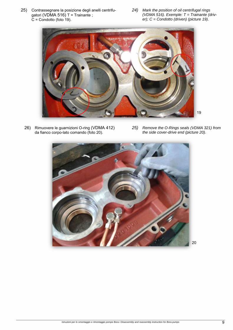
25) Contrassegnare la posizione degli anelli centrifu-gatori (VDMA 516) T = Trainante ; C = Condotto (foto 19).
24) Mark the position of oil centrifugal rings (VDMA 516). Exemple: T = Trainante (driv-er); C = Condotto (driven) (picture 19).
26) Rimuovere le guarnizioni O-ring (VDMA 412) da fianco corpo-lato comando (foto 20).
25) Remove the O-Rings seals (VDMA 321) from the side cover-drive end (picture 20).
19
20

Istruzioni per lo smontaggio e rimontaggio pompe Bora / Disassembly and reassembly instruction for Bora pumps 10
RIMOZIONE
TENUTE A LABIRINTO LABYRINTH SEAL
REMOVAL
1) Con un attrezzo di diametro opportuno e la pres-sa, espellere la tenuta (VDMA 423) (foto 21).
1) Push out the seals (VDMA 423) using a
cylindrical tool and a press (picture 21).
2) Rimuovere la bussola distanziale (VDMA 525), Scaldandola, se necessario (foto 22).
2) Remove the spacer sleeve (VDMA 525), By
heating it, if necessary (picture 22).
21
22

Istruzioni per lo smontaggio e rimontaggio pompe Bora / Disassembly and reassembly instruction for Bora pumps 11
ISTRUZIONI PER LO
SMONTAGGIO DELLA LANTERNA
MOTORE DELLE POMPE SERIE HV
DISASSEMBLY INSTRUCTIONS
OF THE MOTOR LANTERN FOR
PUMPS SERIES HV
1) Drenare completamente lubrificante. 1) Drain the lubricant completely.
2) Togliere il motore. 2) Remove the electric motor.
3) Misurare e annotare la posizione assiale del semi-giunto (VDMA 863) (foto 23).
3) Measure and take note of the half-joint axial
position (VDMA 863) (picture 23).
4) Bloccare la rotazione, agire sui grani per
estrarre e rimuovere il mozzo giunto co-nico (VDMA 863) (foto 24).
4) Lock the rotation, act on the grubs to extract and remove the coupling hub conical lock (VDMA 863) (picture 24).
23
24
Istruzioni per lo smontaggio e rimontaggio pompe Bora / Disassembly and reassembly instruction for Bora pumps 12
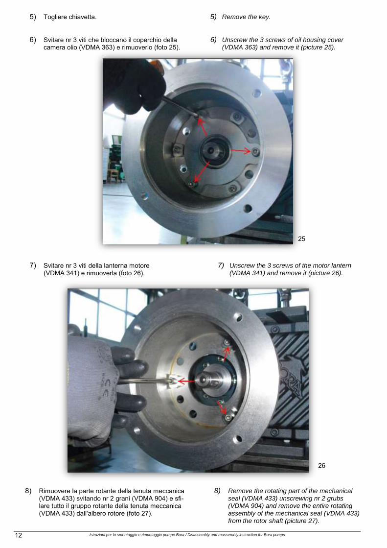
5) Togliere chiavetta. 5) Remove the key.
6) Svitare nr 3 viti che bloccano il coperchio della camera olio (VDMA 363) e rimuoverlo (foto 25).
6) Unscrew the 3 screws of oil housing cover (VDMA 363) and remove it (picture 25).
7) Svitare nr 3 viti della lanterna motore
(VDMA 341) e rimuoverla (foto 26). 7) Unscrew the 3 screws of the motor lantern
(VDMA 341) and remove it (picture 26).
8) Rimuovere la parte rotante della tenuta meccanica (VDMA 433) svitando nr 2 grani (VDMA 904) e sfi-lare tutto il gruppo rotante della tenuta meccanica (VDMA 433) dall'albero rotore (foto 27).
8) Remove the rotating part of the mechanical seal (VDMA 433) unscrewing nr 2 grubs (VDMA 904) and remove the entire rotating assembly of the mechanical seal (VDMA 433) from the rotor shaft (picture 27).
25
26
Istruzioni per lo smontaggio e rimontaggio pompe Bora / Disassembly and reassembly instruction for Bora pumps 13
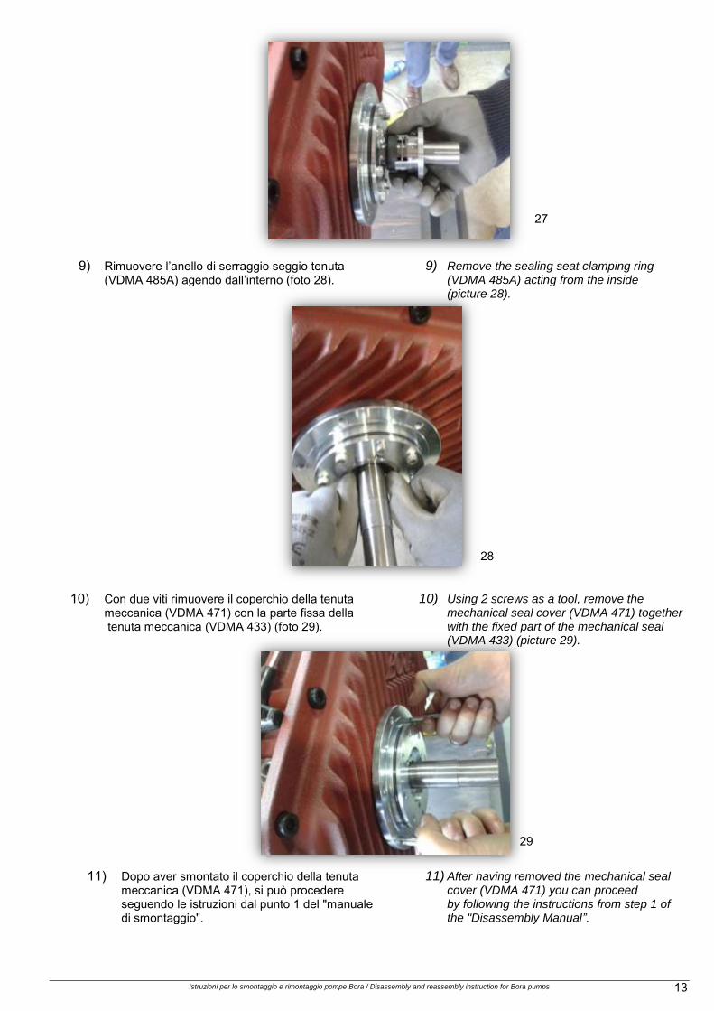
9) Rimuovere l’anello di serraggio seggio tenuta (VDMA 485A) agendo dall’interno (foto 28).
9) Remove the sealing seat clamping ring (VDMA 485A) acting from the inside (picture 28).
10) Con due viti rimuovere il coperchio della tenuta meccanica (VDMA 471) con la parte fissa della tenuta meccanica (VDMA 433) (foto 29).
10) Using 2 screws as a tool, remove the mechanical seal cover (VDMA 471) together with the fixed part of the mechanical seal (VDMA 433) (picture 29).
11) Dopo aver smontato il coperchio della tenuta meccanica (VDMA 471), si può procedere seguendo le istruzioni dal punto 1 del "manuale di di smontaggio".
11) After having removed the mechanical seal cover (VDMA 471) you can proceed by following the instructions from step 1 of the "Disassembly Manual”.
27
28
29

Istruzioni per lo smontaggio e rimontaggio pompe Bora / Disassembly and reassembly instruction for Bora pumps 14
ISTRUZIONI PER IL RIMONTAGGIO DELLE POMPE BORA
REASSEMBLY INSTRUCTIONS FOR BORA PUMPS
OPERAZIONI PRELIMINARI. Assicurarsi di avere a disposizione tutti i componenti ne-cessari per il rimontaggio della pompa. Per questa opera-zione si possono consultare i disegni in sezione presenti in questo manuale. Durante le operazioni sono necessari alcuni utensili (chiavi, strumenti di misura, sigillanti, ecc.), si consiglia di leggere il manuale e verificare di averli disponi-bili. NOTA: nelle pagine seguenti vicino al nome dei componenti delle pompe è indicato tra parentesi anche il numero di riferimento VDMA (che si trova nei disegni in sezione). Il montaggio della pompa inizia con la preparazione dei fianchi. 1) Applicare il sigillante Loxeal 5910 o equivalente
nella sede della tenuta a labirinto (foto 30).
PRELIMINARY OPERATIONS Make sure you have all the components required for the pump reassembly. To do this, you can refer to the sec-tion drawings in this manual. Some tools (keys, measuring tools, sealants, etc.) are required during the operations, we recommend you to read the manual and make sure you have available the necessary tools. NOTE: In the following pages, it is indicated in brackets the reference number VDMA of components (which are in the pump section drawings). Pump reassembly begins with the setup of side covers. 1) Apply sealant Loxeal 5910 or equivalent in the
labyrinth seal seat (photo 30).
2) Posizionare sul lato superiore degli spessori da 0,02 mm e procedere a pressare la tenuta meccanica (VDMA 433) nella sede (foto 31).
2) Apply 0.02 mm shims on the upper side of the mechanical seal, than push the mechanical seal (VDMA 433) into the seat (picture 31).
31
30

Istruzioni per lo smontaggio e rimontaggio pompe Bora / Disassembly and reassembly instruction for Bora pumps 15
3) Pulire il sigillante in eccesso sul lato esterno della sede dei labirinti.
4) Misurare la quota fra il piano nel fianco lato opposto comando e lo spallamento delle due sedi cuscinetti (foto 32).
5) Misurare per ognuno dei due mozzi rotori lato opposto comando la quota che assomma la bussola distanziale + (VDMA 525) + anello centrifugatore olio (VDMA 516) (foto 33). Confrontata con la rispettiva sede nel fianco deve evidenziare differenze che corrispondono ai giochi assiali come da tabella 1 (fianco ing / rotore). Se necessario, lavorare il lato verso il cuscinetto degli anelli centrifugatori olio con lapidello.
6) Riscaldare a 70 °C e inserire le bussole distanziali
(VDMA 525) nei mozzi rotori lato opposto comando (foto 34).
3) Clean the excess of sealant on the external side
of the labyrinths. 4) Measure the dimension between the level in the
side cover non drive-end and the shoulder of the two bearing seats (picture32).
5) Measuring for each of the two rotor hubs the dimension of the spacer sleeve (VDMA 525) + the oil centrifugal ring ((VDMA 516) (picture 33). Compared with the respective seat in the cover side It should highlight the differences that correspond to the games Axial according to table 1 (axial backlash gear side). If necessary, work the side towards the bearing of the oil f centrifugal rings with lapidello.
6) Heat to 70 ° C and insert the spacer sleeves ( VDMA 525) into rotor hubs non drive-end (picture 34).
32
33
34

Istruzioni per lo smontaggio e rimontaggio pompe Bora / Disassembly and reassembly instruction for Bora pumps 16
7) Utilizzare il fianco corpo-lato comando (VDMA 117A) come base per rotori. Assicurarsi di avere un piano di appoggio pulito, ad esempio dispo-nendo un foglio di carta pulita sul piano (foto 35 e 36).
7) Use the side cover-drive end (VDMA 117A) as a base for the rotors (VDMA 280). Be sure to have a clean surface plane, for example you can put a clean sheet of paper on the plane (pictures 35 and 36).
8) Infilare i rotori (VDMA 280) nei fori del fianco corpo lato comando (foto 37).
8) Insert the rotors (VDMA 280) in the holes of the side cover drive-end (picture 37).
9) Appoggiare il fianco corpo-lato opposto comando (VDMA 117B) sui rotori (foto 38).
9) Lay the side cover non-drive end (VDMA 117B) on the rotors (picture 38).
10) Inserire gli anelli centrifugatori olio (VDMA 516) e ricordarsi le marcature T e C (foto 39 e 40 e 41).
10) Insert the oil centrifugal rings (VDMA 516) and remember the marks T and C (pictures 39, 40 41).
35 36
37 38
39 40
41

Istruzioni per lo smontaggio e rimontaggio pompe Bora / Disassembly and reassembly instruction for Bora pumps 17
11) Inserire cuscinetti a doppia corona di sfere a contatto obliquo (VDMA 321) dopo aver scaldato la pista interna a 80 °C (foto 42).
11) Insert the double row angular contact ball bearing (VDMA 321) after heating their inner ring at 80°C (picture 42).
12) Rimuovere la schermatura dai cuscinetti a dop-pia corona di sfere a contatto obliquo (VDMA 321) dal lato carter-lato opposto comando (foto 43).
12) Remove the double row angular contact ball bearing (VDMA 321) screens from the sump non drive-end side (picture 43).
9
13) Applicare Loxeal 24 18 o equivalente frena fi-letti a bassa resistenza in 6 fori M8 (foto 44).
13) Apply Loxeal 24 18 or equivalent low resistance thread locker in the 6 holes size M8 (picture 44).
14) Montare il coperchio cuscinetto (VDMA 360) e serrare le 6 viti M8 a 30 Nm.
14) Mount the bearing cover (VDMA 360) and tighten the 6 screws size M8 at 30 Nm.
15) Per le macchine taglia 673÷1083 posizionare gli anelli distanziali (VDMA 504), inserire le bussole di centraggio (VDMA 526) e i nuovi ca-lettatori (VDMA 930) (foto 45A e 45B). Posizionare gli ingranaggi (VDMA 870) rispet-tando la fasatura, utilizzare sotto agli ingranag-gi uno spessore da 6 mm (foto 46) quindi posi-zionare le bussole di spinta (VDMA 533) (foto 47).
15) For the 673÷1083 pumps size position the spacer rings (VDMA 504), insert the centering sleeve (VDMA 526) and the new locking ele-ments (VDMA 930) (picture 45A e 45B). Place the gears (VDMA 870) respecting the timing, use a thickness of 6 mm below the gears (photo 46) and place the thrust sleeves (VDMA 533) (photo 47).
42
43
44

Istruzioni per lo smontaggio e rimontaggio pompe Bora / Disassembly and reassembly instruction for Bora pumps 18
45A
46
47
Posizione dei calettatori (VDMA 930) (673÷1083). Locking elements position (VDMA 930) (673÷1083).
45B

Istruzioni per lo smontaggio e rimontaggio pompe Bora / Disassembly and reassembly instruction for Bora pumps 19
16) Applicare i frena filetti Loxeal 55 02 o prodotto equivalente nei fori M10 del rotore condotto (foto 48). Posizionare le rondelle di spinta estremità albero a 3 fori e serrare le tre viti M10 del rotore condotto a 70 Nm e del rotore trainante a 40 Nm (foto 50), bloccando la rotazione dei rotori (foto 49).
16) Apply thread lock Loxeal 55 02 or equivalent product in the three holes M10 of the driven rotor (picture 48).Put in position the shaft-end thrust washer with three holes and screw in the three hexagon cap screws M1 of the driven rotor at 70 Nm and of the driver rotor at 40 Nm. (picture 50), locking the rotors in position (picture 49).
48
49
50

Istruzioni per lo smontaggio e rimontaggio pompe Bora / Disassembly and reassembly instruction for Bora pumps 20
17) Con chiave dinamometrica serrare la vite M12 della rondella di spinta estremità albero a 80 Nm.
17) With a torque wrench tighten the screws size M12 of the shaft-end thrust washer at 80 Nm.
18) Per le macchine taglia 163÷463 posizionare gli ingranaggi (VDMA 870) rispettando la fasatura (foto 51). Montare i calettatori (VDMA 930) con 16 viti TCEI nuove M6 grado 12.9 senza serrarle. Applicare Loxeal 55 02 o equivalente collante media resistenza nel foro M12 del mozzo del ro-tore condotto (VDMA 280) (foto 51). Con chiave dinamometrica serrare la vite M12 del rotore condotto a 40 Nm (foto 52).
19) Avvitare a mano le 8+8 viti M6 dei calettatori. Serrare procedendo in modo incrociato le 8 viti M6 del calettatore ingranaggio rotore condotto a 16 Nm (foto 53). Con chiave dinamometrica ser-rare la vite M12 del rotore trainante a 80Nm.
18) For the 163÷463 pumps size Place the gears (VDMA 870) respecting the timing (picture 51). Mount the locking elements (VDMA 930) using 16 new hex socket head cap screws, without tightening. Apply Loxeal 55 02 or equivalent me-dium strength adhesive in the hole M12 of the ro-tor hub (VDMA 280) (photo 51). With a torque wrench, tighten the M12 screws of the driven rotor at 40 Nm (52 photos)
19) Tighten by hand the 8 + 8 M6 screws of the lock-ing elements. (VDMA 930). Tighten the number 8 screws size M6 of the driven rotor locking ele-ment moving crosswise at 16 Nm (picture 53). Tigthen with torque wrench the M12 screw of the driving rotor to 80Nm.
51
52

Istruzioni per lo smontaggio e rimontaggio pompe Bora / Disassembly and reassembly instruction for Bora pumps 21
20) Tramite golfari M8 nei fori per piedi, sollevare fianco corpo-lato opposto comando (VDMA 117B) e rotori (VDMA 280) e calare nel corpo (foto 54).
20) Using two eyebolt size M8 mounted in the feet holes lift the side cover-non drive (VDMA 117B) end and rotors (VDMA 280) and lower them in-side the casing (picture 54).
54
53
Istruzioni per lo smontaggio e rimontaggio pompe Bora / Disassembly and reassembly instruction for Bora pumps 22
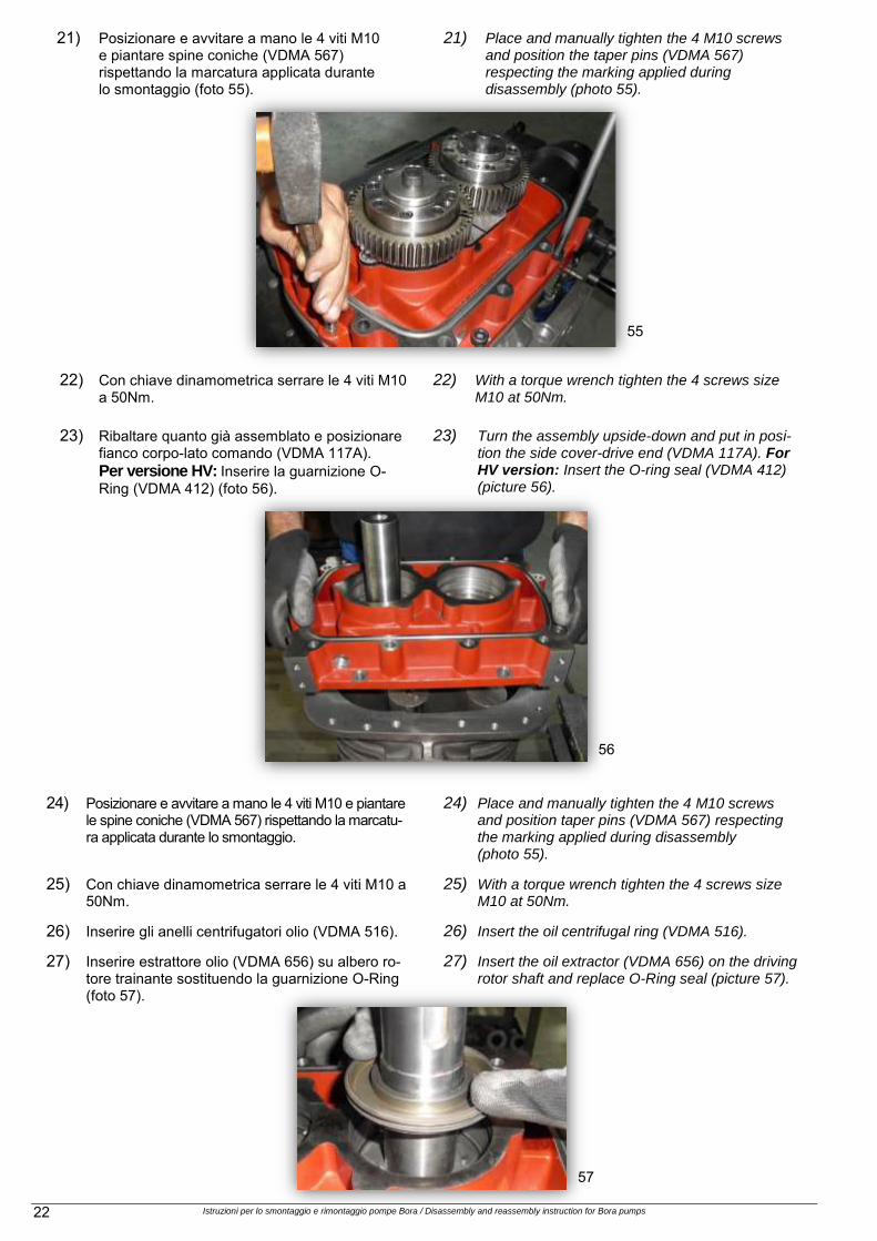
21) Posizionare e avvitare a mano le 4 viti M10 e piantare spine coniche (VDMA 567) rispettando la marcatura applicata durante lo smontaggio (foto 55).
21) Place and manually tighten the 4 M10 screws and position the taper pins (VDMA 567) respecting the marking applied during disassembly (photo 55).
22) Con chiave dinamometrica serrare le 4 viti M10 a 50Nm.
22) With a torque wrench tighten the 4 screws size M10 at 50Nm.
23) Ribaltare quanto già assemblato e posizionare fianco corpo-lato comando (VDMA 117A). Per versione HV: Inserire la guarnizione O-Ring (VDMA 412) (foto 56).
23) Turn the assembly upside-down and put in posi-tion the side cover-drive end (VDMA 117A). For HV version: Insert the O-ring seal (VDMA 412) (picture 56).
24) Posizionare e avvitare a mano le 4 viti M10 e piantare le spine coniche (VDMA 567) rispettando la marcatu-ra applicata durante lo smontaggio.
24) Place and manually tighten the 4 M10 screws and position taper pins (VDMA 567) respecting the marking applied during disassembly (photo 55).
25) Con chiave dinamometrica serrare le 4 viti M10 a 50Nm.
25) With a torque wrench tighten the 4 screws size M10 at 50Nm.
26) Inserire gli anelli centrifugatori olio (VDMA 516). 26) Insert the oil centrifugal ring (VDMA 516).
27) Inserire estrattore olio (VDMA 656) su albero ro-tore trainante sostituendo la guarnizione O-Ring (foto 57).
27) Insert the oil extractor (VDMA 656) on the driving rotor shaft and replace O-Ring seal (picture 57).
55
56
57

Istruzioni per lo smontaggio e rimontaggio pompe Bora / Disassembly and reassembly instruction for Bora pumps 23
28) Posizionare nr 2 guarnizioni O-Ring nelle cave all’interno delle sedi dei cuscinetti.
28) Put in place nr 2 O-Rings seals in the grooves inside the bearing housing.
29) Inserire i cuscinetti a una corona di sfere (VDMA 320).
29) Insert the single row ball bearings (VDMA 320).
30) Rimuovere schermatura lato carter lato comando dai cuscinetti (foto 58)
30) Remove the bearing screens on the sump drive-end side (picture 58).
31) Posizionare rondella di spinta estremità albero (VDMA 552) su mozzo rotore condotto; applicare Loxeal 55 02 o equivalente collante media resi-stenza nel foro M12; utilizzare blocco di plastica per impedire rotazione rotore condotto e serrare con chiave dinamometrica la vite M12 a 100 Nm (foto 59).
31) Place the shaft-end thrust washer (VDMA 552) on the driven rotor hub, apply Loxeal 55 02 or equivalent medium strength adhesive in the M12 hole, use a plastic block to prevent the rotation of the driven rotor and use a torque wrench to tighten the screw size M12 at 100 Nm (picture 59).
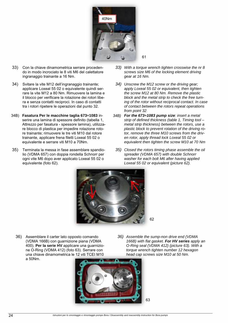
32) Fasatura dei rotori: Per le macchine taglia 163÷463: inse-rire una lamina di spessore definito (tabella 1, Attrezzo per fasatura - spessore lamina) fra i rotori, utilizzare blocco di plastica per impedire rotazione rotore trainante; serrare la vite M12 del rotore trainante a 40Nm (foto 60 - 61)
32) Rotors timing: For the 163÷463 pump size: insert a metal strip of defined thickness (table 1, Tim-ing tool – metal strip thickness) between the ro-tors, use a plastic block to prevent rotation of the drive rotor and tighten the screws M12 of the driving rotor at 40 Nm (picture 60 – 61). .
60
58
59
Istruzioni per lo smontaggio e rimontaggio pompe Bora / Disassembly and reassembly instruction for Bora pumps 24
33) Con la chiave dinamometrica serrare proceden-do in modo incrociato le 8 viti M6 del calettatore ingranaggio trainante a 16 Nm.
33) With a torque wrench tighten crosswise the nr 8 screws size M6 of the locking element driving gear at 16 Nm.
34) Svitare la vite M12 dell’ingranaggio trainante; applicare Loxeal 55 02 o equivalente quindi ser-rare la vite M12 a 80 Nm. Rimuovere la lamina e il blocco per verificare la rotazione dei rotori libe-ra e senza contatti reciproci. In caso di contatti tra i rotori ripetere le operazioni dal punto 32.
34) Fasatura Per le macchine taglia 673÷1083 in-serire una lamina di spessore definito (tabella 1, Attrezzo per fasatura - spessore lamina), utilizza-re blocco di plastica per impedire rotazione roto-re trainante; rimuovere le tre viti M10 dal rotore trainante, applicare frena filetti Loxeal 55 02 o equivalente e serrare viti M10 a 70Nm.
34) Unscrew the M12 screw or the driving gear; apply Loxeal 55 02 or equivalent, then tighten the screw M12 at 80 Nm. Remove the plastic block and the metal strip to check the free turn-ing of the rotor without reciprocal contact. In case of contact between the rotors repeat operations from point 32.
34) For the 673÷1083 pump size: insert a metal strip of defined thickness (table 1, Timing tool – metal strip thickness) between the rotors, use a plastic block to prevent rotation of the driving ro-tor, remove the three M10 screws from the driv-en rotor, apply thread lock Loxeal 55 02 or equivalent then tighten the screw M10 at 70 Nm
35) Terminata la messa in fase assemblare spandio-lio (VDMA 657) con doppia rondella Schnorr per ogni vite M6 dopo aver applicato Loxeal 55 02 o equivalente (foto 62).
35) Closed the rotors timing phase assemble the oil spreader (VDMA 657) with double Schnorr washer for each bolt M6 after having applied Loxeal 55 02 or equivalent (picture 62).
36) Assemblare il carter lato opposto comando (VDMA 166B) con guarnizione piana (VDMA 400). Per la serie HV applicare una guarnizio-ne O-Ring (VDMA 412) (foto 63). Serrare con una chiave dinamometrica le 12 viti TCEI M10 a 50Nm.
36) Assemble the sump-non drive end (VDMA 166B) with flat gasket. For HV series apply an O-Ring seal (VDMA 412) (picture 63). With a torque wrench tighten number 12 hexagon head cap screws size M10 at 50 Nm.
62
63
40Nm
34B) 34B)
61

Istruzioni per lo smontaggio e rimontaggio pompe Bora / Disassembly and reassembly instruction for Bora pumps 25
37) Inserire gli anelli di spallamento (VDMA 505), le 2 molle a tazza (VDMA 950) e lo spandiolio (VDMA 657) sull’albero rotore trainante.
37) Insert the shoulder ring (VDMA 505) the 2 cup springs (VDMA 950) and the oil spreader (VDMA 657) on driving rotor shaft.
38) Inserire la guarnizione O-Ring nella sede cuscinet-to del carter lato comando, posizionare cuscinetto a 1 corona di sfere (VDMA 320), rimuovere la schermatura lato fianco corpo (escluso serie HV) (foto 65).
38) Insert the O-Ring seal in the bearing housing of the sump drive-end, place the single row ball bearing (VDMA 320)in site, remove the bearing screen side cover side (excluded HV series) (picture 65).
39) Applicare Loctite 272 o prodotto equivalente sul-la pista interna cuscinetto carter lato comando (non per serie HV).
39) Apply Loctite 272 or equivalent product on bearing inner ring surface on sump drive-end (not for HV series).
40) Posizionare guarnizione piana (VDMA 400) Per la serie HV un O-Ring (VDMA 412).
40) Put in place the flat gasket (VDMA 400). For HV series an O-Ring seal (VDMA 412).
41) Utilizzando un attrezzo a tubo (diametro interno 46 mm e diametro esterno 84 mm) montare fian-co corpo lato comando (VDMA 166A) inserendo contestualmente il cuscinetto a 1 corona di sfere (VDMA 320) sul rotore (foto 66).
41) Using a special pipe tube (inner diameter 46 mm, external diameter 84 mm) assembly side cove drive-end (VDMA 166A) and the single row ball bearing (VDMA 320) on the rotor together (picture 66).
64
65
66

Istruzioni per lo smontaggio e rimontaggio pompe Bora / Disassembly and reassembly instruction for Bora pumps 26
42) Avvitare manualmente le 12 viti M12. 42) Screw in by hand nr 12 screws size M12.
43) Esercitando una forza di 600N sul carter verso flangia di mandata, serrare le 12 viti M12 50 Nm controllando la libera rotazione dell’albero rotore (foto 67).
43) Apply a 600N force on the carter on drive side and tighten number 12 screws M12 size at 50 Nm. Check the free rotation of the rotor shaft. (picture 67)
44) Utilizzando l’attrezzo a tubo precedente, agire sul pacco anelli spessore sporgente 1 mm con un impulso esterno (martello di plastica) e far spostare il cuscinetto a 1 corona di sfere (VDMA 320) verso l’interno (foto 68 e 69).
44) Using the tubular tool used above, act on the thickness rings assembly that is protruding 1 mm with an impulsive thrust (plastic mallet), push the single row ball bearing 8VDMA 320) to the inside (pictures 68 and 69).
67
68
69

Istruzioni per lo smontaggio e rimontaggio pompe Bora / Disassembly and reassembly instruction for Bora pumps 27
45) Montare i tappi (VDMA 903) e i livelli visivi dell’olio lubrificante (foto 70).
45) Assembly the plugs (VDMA 903) and the lubricating oil glass gauges (picture 70).
46) Al termine del montaggio, prima di collegare il motore, ruotare manualmente per favorire un rodaggio fra la tenuta e la boccola fino ad ottene-re una rotazione libera da attrito.
46) Once assembled before connecting the motor, rotate manually the driving shaft, to facilitate a running between the seal and the bushing, until the rotation will be free from any friction.
47) Riempimento lubrificante: seguire il manuale operativo per modalità e quantità.
47) Lube filling: follow the operating manual for pro-cedure and quantity.
70

Istruzioni per lo smontaggio e rimontaggio pompe Bora / Disassembly and reassembly instruction for Bora pumps 28
ISTRUZIONI ADDIZIONALI PER
VACUUM BOOSTER HV
ADDITIONAL INSTRUCTIONS FOR
VACUUM BOOSTER HV
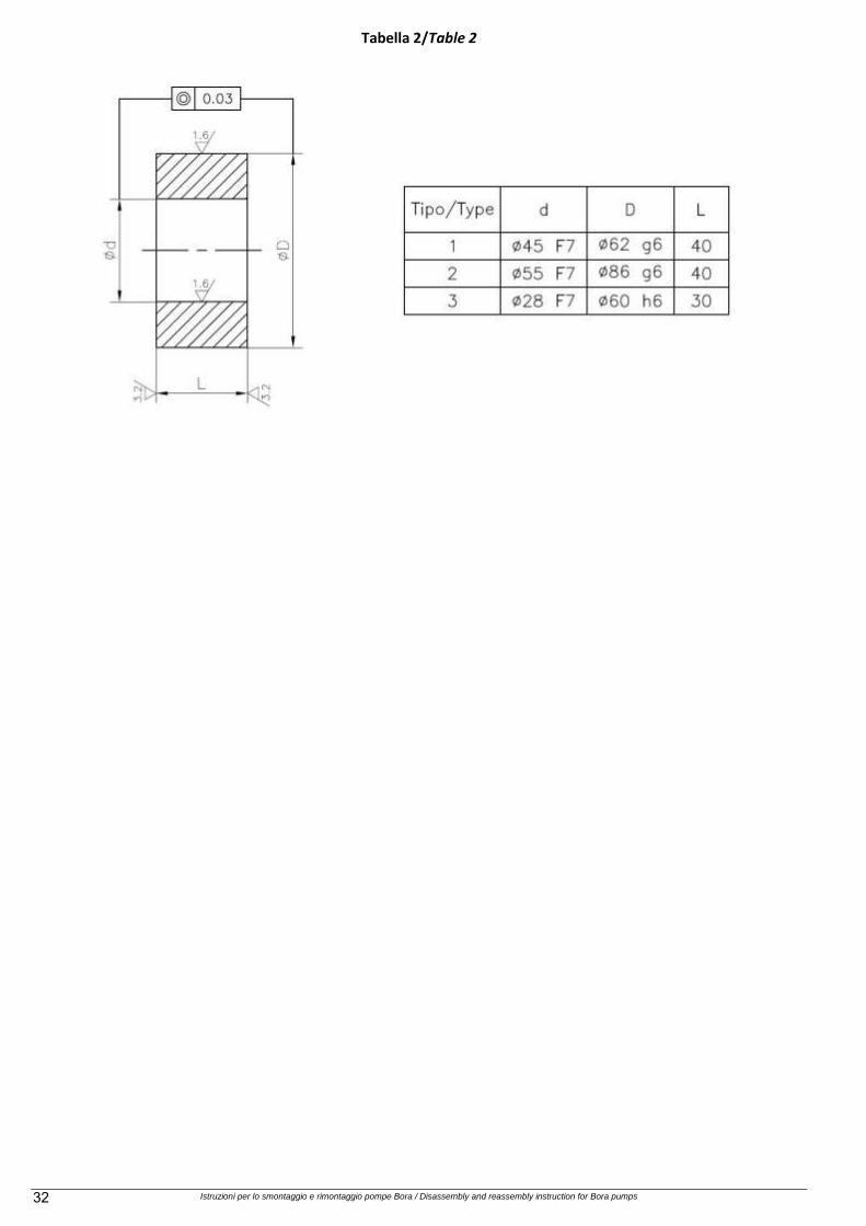
48) Montare carter lato comando (VDMA 166A) con la bussola di centraggio (VDMA 526). Vedere ta-bella 2, boccola 1 per modelli 163÷463, boccola 2 per modelli 673÷1083 (foto 71).
48) Assembly the sump-drive end (VDMA 166A) with the centering sleeve (VDMA 526). See ta-ble 2, type 1 for pump models 163÷463, type 2 for models 673÷1083 (picture 71).
49) Montare il coperchio tenuta meccanica (VDMA 471) sul carter-lato comando (foto 72).
49) Assembly the mechanical seal cover (VDMA 471) on the sump-drive end (picture 72).
31
50) Montare la tenuta meccanica (VDMA 433) com-pleta di anello di serraggio seggio, controllando che la coda della tenuta sia a 28 mm dal coper-chio della tenuta meccanica (+ 4 mm di anello spandi olio se presente) (foto 73).
50) Assembly the mechanical seal (VDMA 433) in-cluding the sealing seat clamping ring, taking care that the seal tail is at 28 mm from the me-chanical seal cover surface (+ 4 mm for the Oil spreader, if it is present) (picture 73).
32
33
71
72
73

Istruzioni per lo smontaggio e rimontaggio pompe Bora / Disassembly and reassembly instruction for Bora pumps 29
51) Montare la lanterna motore (VDMA 341) sul co-perchio tenuta meccanica e fissarla con le tre viti e apposite rondelle piane sagomate (foto 74).
51) Assembly the motor lantern (VDMA 341) on the mechanical seal cover with the 3 screws and dedicate shaped flat washer (picture 74).
52) Montare il coperchio camera olio (VDMA 363) proteggendo l’anello di tenuta radiale (VDMA 421) dalla sede chiavetta e dal gradino sull’albero rotore. Utilizzare eventualmente una bussola sottile o rivestire provvisoriamente di nastro l’albero rotore (foto 75).
52) Assembly oil housing cover (VDMA 363) taking care to protect the radial shaft seal ring (VDMA 421) from the shaft key slot and the rotor shaft step. Could be eventually used a thin bushing or a temporary tape cover on the rotor shaft (picture 75).
53) Prima di fissare il coperchio della camera olio (VDMA 363) rimuovere le protezioni provviso-rie utilizzate e posizionarlo in centro utilizzando la bussola apposita (tabella 2, tipo 3). Una vol-ta posizionato, serrare le tre viti (foto 76).
53) Before fixing the oil housing cover (VDMA 363) remove the temporary protections and position it on center using the dedicated bushing (table 2, type 3). Once in place, tighten the three screws (picture 75).
74
75

Istruzioni per lo smontaggio e rimontaggio pompe Bora / Disassembly and reassembly instruction for Bora pumps 30
54) Rimontare il semi-giunto (VDMA 863) nella posi-zione assiale misurata allo smontaggio (foto 76).
55) Assembly the half-joint (VDMA 863) in the axial position measured and noted during disassembly operation (picture76).
56) Riempimento della camera olio della lanterna motore col lubrificante: seguire il manuale ope-rativo per modalità e quantità (foto 77).
56) Lube filling motor lantern: follow the operating manual for procedure and quantity (picture77).
75
76
7

Istruzioni per lo smontaggio e rimontaggio pompe Bora / Disassembly and reassembly instruction for Bora pumps 31
Tabella 1/Table 1
Mis
ure
in m
illi
met
ri/M
easu
res
in m
illi
met
ers
Istruzioni per lo smontaggio e rimontaggio pompe Bora / Disassembly and reassembly instruction for Bora pumps 32
Tabella 2/Table 2

Istruzioni per lo smontaggio e rimontaggio pompe Bora / Disassembly and reassembly instruction for Bora pumps 33
VDMA

Istruzioni per lo smontaggio e rimontaggio pompe Bora / Disassembly and reassembly instruction for Bora pumps 34

Istruzioni per lo smontaggio e rimontaggio pompe Bora / Disassembly and reassembly instruction for Bora pumps 35
Soffiatore serie 73-103/Blower 73-103
––

Istruzioni per lo smontaggio e rimontaggio pompe Bora / Disassembly and reassembly instruction for Bora pumps 36
Soffiatore serie 163-463/Blower 163-463

Istruzioni per lo smontaggio e rimontaggio pompe Bora / Disassembly and reassembly instruction for Bora pumps 37
Soffiatore serie 673-1083/Blower 673-1083

Istruzioni per lo smontaggio e rimontaggio pompe Bora / Disassembly and reassembly instruction for Bora pumps 38
Booster vuoto serie 163÷463/Vacuum Booster 163÷463

Istruzioni per lo smontaggio e rimontaggio pompe Bora / Disassembly and reassembly instruction for Bora pumps 39
Booster vuoto serie 673÷1083/Vacuum Booster 673÷1083

Istruzioni per lo smontaggio e rimontaggio pompe Bora / Disassembly and reassembly instruction for Bora pumps 40
LA NOSTRA PRODUZIONE/OUR PRODUCTION
POMPE CENTRIFUGHE MONOSTADIO MONOSTAGE CENTRIFUGAL PUMPS
POMPE CENTRIFUGHE MONOSTADIO
A TRASCINAMENTO MAGNETICO MAGNETIC DRIVE
MONOSTAGE CENTRIFUGAL PUMPS
POMPE AUTOADESCANTI CENTRIFUGHE SELF-PRIMING CENTRIFUGAL PUMPS
POMPE AUTOADESCANTI CENTRIFUGHE
A TRASCINAMENTO MAGNETICO MAGNETIC DRIVE
SELF-PRIMING CENTRIFUGAL PUMPS
POMPE CENTRIFUGHE MULTISTADIO MULTISTAGE CENTRIFUGAL PUMPS
POMPE PER VUOTO AD ANELLO DI LIQUIDO
LIQUID RING VACUUM PUMPS
COMPRESSORI AD ANELLO DI LIQUIDO LIQUID RING COMPRESSORS
GRUPPI AUTONOMI PER VUOTO A RICIRCOLO
TOTALE O PARZIALE DI LIQUIDO PACKAGE VACUUM UNITS WITH PARTIAL OR TOTAL
SERVICE LIQUID RECIRCULATION
NA5.IS.BORA.IGB0 / STAMPATO IN ITALIA Manuale Smontaggio e Rimontaggio Pompetravaini-BORA Ita Eng
La continua ricerca della POMPETRAVAINI ha come obiettivo il miglioramento del prodotto: per questo si riserva il diritto di modificare le caratteristiche senza alcun preavviso. Continuing research of POMPETRAVAINI results in product improvements: therefore any specifications may be subject to change without notice.
POMPETRAVAINI S.p.A.
Via per Turbigo, 44 - Zona Industriale 20022 CASTANO PRIMO - (Milano) – ITALIA Tel. +39 0331 889000 - Fax. 0331 889090 -
www.pompetravaini.com
Divisione BORA sede operativa:
Via della Scienza, 56 41122 MODENA – ITALY
Tel. +39 059 284210 - Fax +39 059 284042