Embed Size (px)
Citation preview
1733
Journal of Engineering Sciences, Assiut University, Vol. 40 No 6 pp.1733-1745 - November 2012
A COMPACT ULTRA-WIDE BAND MICROSTRIP SLOTTED ANTENNA WITH DUAL BAND NOTCHED
M. Mamdouh, and Elsayed Esam M. khaled
Electrical Engineering Department, Assiut University. Faculty of Engineering
Assiut, Egypt-Postal Code: 71518 E-mail: [email protected]
(Received May 30, 2012 Accepted July 7, 2012)
ABSTRACT This paper presents a design of a compact and simple ultra-wide band planar
antenna with dual band notched. The antenna consists of a microstrip-fed line and two rectangular slots in the ground plane. The design produces a wide band operation with return loss less than -10dB in the frequency range of 2 to 9.5 GHz. By using a rectangular patch in conjunction with a U patch and etching a U-shaped slot in the feed line, the band of the antenna is increased with two notched bands of central frequencies at 3.5GHz and 5.5 GHz. Defected ground plane and an open shunt stub are proposed to improve the impedance bandwidth of the presented antenna. Parametric studies of antenna elements are presented. The proposed antenna is fabricated. The measured data show very good agreement with the simulated results. Key words: ultra wide band (UWB), microstrip feed line, dual band notched, planar antenna
1. INTRODUCTION
Recently, the microstrip patch planar antennas play an increasingly important role in communication systems operated in the ultra-wide band (UWB) due to their attractive merits, such as small size, low cost and ease of fabrication. Ever since the Federal Communication Commission (FCC) released the unlicensed UWB spectrum within the range 3.1-10.6 GHz for the commercial purpose, the design of UWB patch antenna has attracted considerable interest in both the academic society and wireless industry community. Such types of antennas have many advantages such as low power consumption, support of high secured data rate and simple configuration [1]. However, there are some other existing narrowband systems, such as WLAN system (IEEE802.11a and HIPERLAN/2) operates in the band of 5.2-5.8 GHz and the WiMAX system in 3.2-3.8 GHz band which may cause severe electromagnetic interference to UWB antenna operation. To avoid such possible interference between UWB system and WLAN/ WiMAX systems without adding filtering circuits, it’s desirable to design UWB antennas with dual notched bands in both 3-4 GHz and 5-6 GHz. In the last few years, band-notched UWB planar antennas based on various techniques have been proposed. The conventional methods are etching slots of different shapes either of the radiating patch or the ground plane [2-8], adding parasitic elements near the patch [9], using an electromagnetic band gap (EBG) structures [10],
M. Mamdouh, and Elsayed Esam M. khaled 1734
and using spiral loop resonator [11]. However, most of these antennas can perform only one notched frequency band. Several ways such as using two U-shaped slots in the radiation patch and an rectangular slot in the circular polarized wave (CPW) ground [12], loading L-type band stop filter and inserting a split ring resonator (SRR) [13], using two pairs of EBG cells which are designed to act as stop-band filters [14], and etching a C-shaped in the feed line and a C-shaped slit on the T-stub [15] can provide the requirement band notched .
In this paper, a new and simple UWB patch antenna with dual band notched is proposed. The dual band-notched response in both 3-4 GHz and 5-6 GHz is achieved by etching a U-shaped slot in microstrip feed line and inserting a U-shaped patch with conjunction with a rectangular patch.
2. ANTENNA DESIGN AND RESULTS
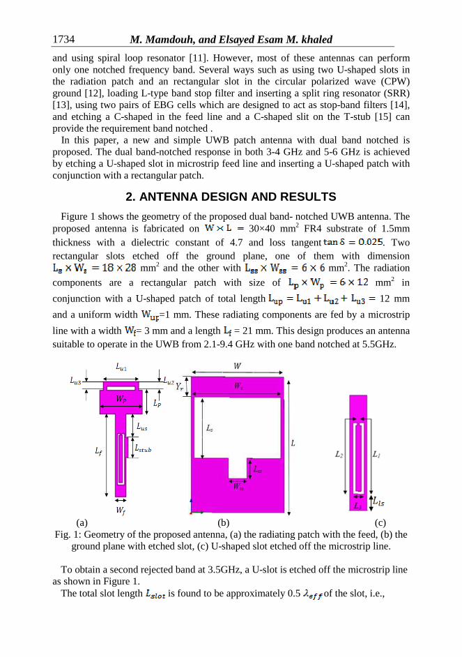
Figure 1 shows the geometry of the proposed dual band- notched UWB antenna. The proposed antenna is fabricated on 30×40 mm2 FR4 substrate of 1.5mm thickness with a dielectric constant of 4.7 and loss tangent . Two rectangular slots etched off the ground plane, one of them with dimension
mm2 and the other with mm2. The radiation
components are a rectangular patch with size of mm2 in
conjunction with a U-shaped patch of total length 12 mm
and a uniform width =1 mm. These radiating components are fed by a microstrip
line with a width = 3 mm and a length = 21 mm. This design produces an antenna suitable to operate in the UWB from 2.1-9.4 GHz with one band notched at 5.5GHz.
(a) (b) (c)
Fig. 1: Geometry of the proposed antenna, (a) the radiating patch with the feed, (b) the ground plane with etched slot, (c) U-shaped slot etched off the microstrip line.
To obtain a second rejected band at 3.5GHz, a U-slot is etched off the microstrip line
as shown in Figure 1. The total slot length is found to be approximately 0.5 of the slot, i.e.,
A COMPACT ULTRA-WIDE BAND MICROSTRIP SLOTTED …
1735
where is the wavelength at the center frequency of the rejected band which is
given by [16]
where is the free space wavelength, and is the effective dielectric constant of
the narrow slot structure and is given as,
This slot is approximately equal to one half-wavelength at the center frequency of the required stop-band. This resonator introduces high reflection at its resonance frequency. Thus, as a first order approximation, the required slot length to obtain the notch frequency is given by:
where c is the speed of light in free space. Equation (4) is used as a starting point for optimizing the slot length to obtain the more accurate value required to obtain the band-rejection. It is found that the slot length has a greater impact on the band-rejection than the slot width. The three parameters and are the most
significant factors to design the required band rejection. The optimal values are: the slot uniform width is 0.5 mm, mm, = 1 mm, and =3 mm.
To improve the impedance bandwidth, an open stub is proposed to match the input impedance with 50Ω input port as shown in Figure 1. The stub is connected in shunt to the feed line with size of mm2 at a distance =6 mm from
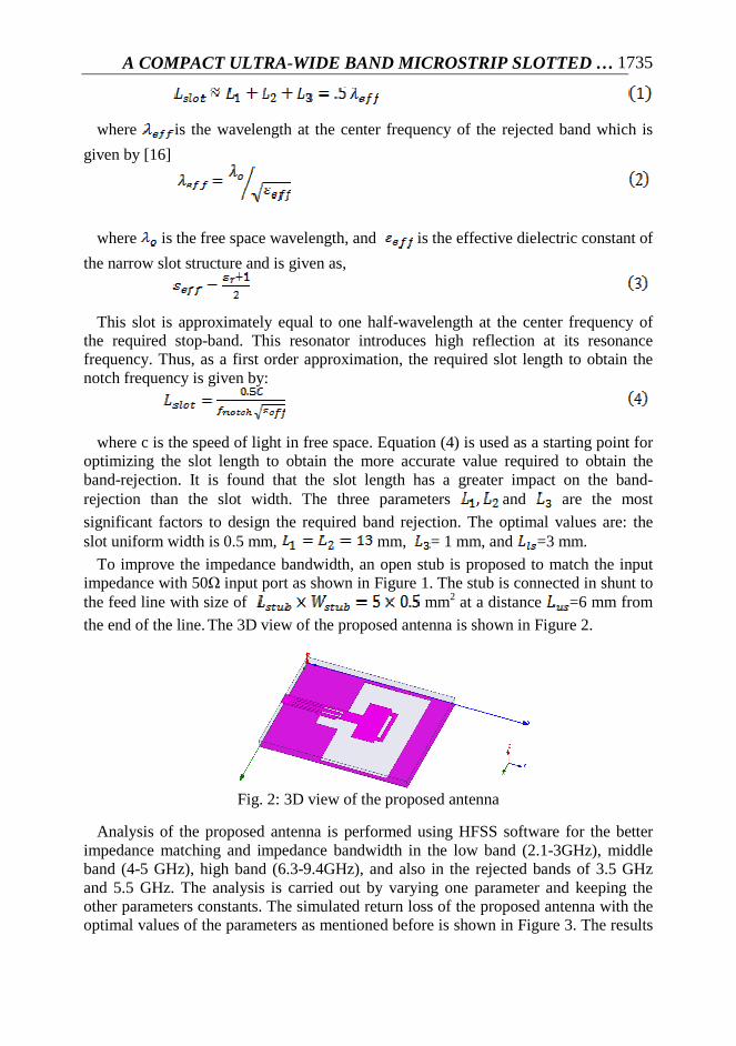
the end of the line. The 3D view of the proposed antenna is shown in Figure 2.
Fig. 2: 3D view of the proposed antenna
Analysis of the proposed antenna is performed using HFSS software for the better impedance matching and impedance bandwidth in the low band (2.1-3GHz), middle band (4-5 GHz), high band (6.3-9.4GHz), and also in the rejected bands of 3.5 GHz and 5.5 GHz. The analysis is carried out by varying one parameter and keeping the other parameters constants. The simulated return loss of the proposed antenna with the optimal values of the parameters as mentioned before is shown in Figure 3. The results
M. Mamdouh, and Elsayed Esam M. khaled 1736
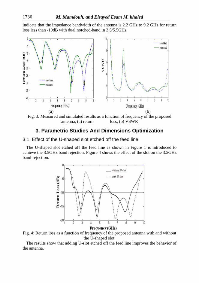
indicate that the impedance bandwidth of the antenna is 2.2 GHz to 9.2 GHz for return loss less than -10dB with dual notched-band in 3.5/5.5GHz.
(a) (b)
Fig. 3: Measured and simulated results as a function of frequency of the proposed antenna, (a) return loss, (b) VSWR
3. Parametric Studies And Dimensions Optimization
3.1. Effect of the U-shaped slot etched off the feed line
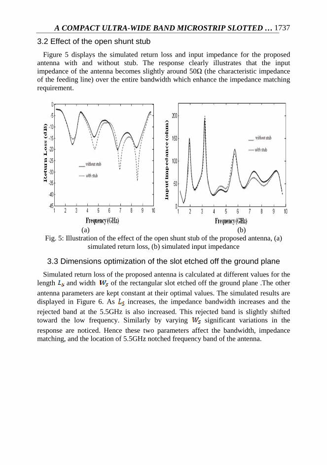
The U-shaped slot etched off the feed line as shown in Figure 1 is introduced to achieve the 3.5GHz band rejection. Figure 4 shows the effect of the slot on the 3.5GHz band-rejection.
Fig. 4: Return loss as a function of frequency of the proposed antenna with and without
the U-shaped slot. The results show that adding U-slot etched off the feed line improves the behavior of
the antenna.
A COMPACT ULTRA-WIDE BAND MICROSTRIP SLOTTED …
1737
3.2 Effect of the open shunt stub
Figure 5 displays the simulated return loss and input impedance for the proposed antenna with and without stub. The response clearly illustrates that the input impedance of the antenna becomes slightly around 50Ω (the characteristic impedance of the feeding line) over the entire bandwidth which enhance the impedance matching requirement.
(a) (b)
Fig. 5: Illustration of the effect of the open shunt stub of the proposed antenna, (a) simulated return loss, (b) simulated input impedance
3.3 Dimensions optimization of the slot etched off the ground plane
Simulated return loss of the proposed antenna is calculated at different values for the length and width of the rectangular slot etched off the ground plane .The other
antenna parameters are kept constant at their optimal values. The simulated results are displayed in Figure 6. As increases, the impedance bandwidth increases and the
rejected band at the 5.5GHz is also increased. This rejected band is slightly shifted toward the low frequency. Similarly by varying significant variations in the
response are noticed. Hence these two parameters affect the bandwidth, impedance matching, and the location of 5.5GHz notched frequency band of the antenna.
M. Mamdouh, and Elsayed Esam M. khaled 1738
(a) (b)
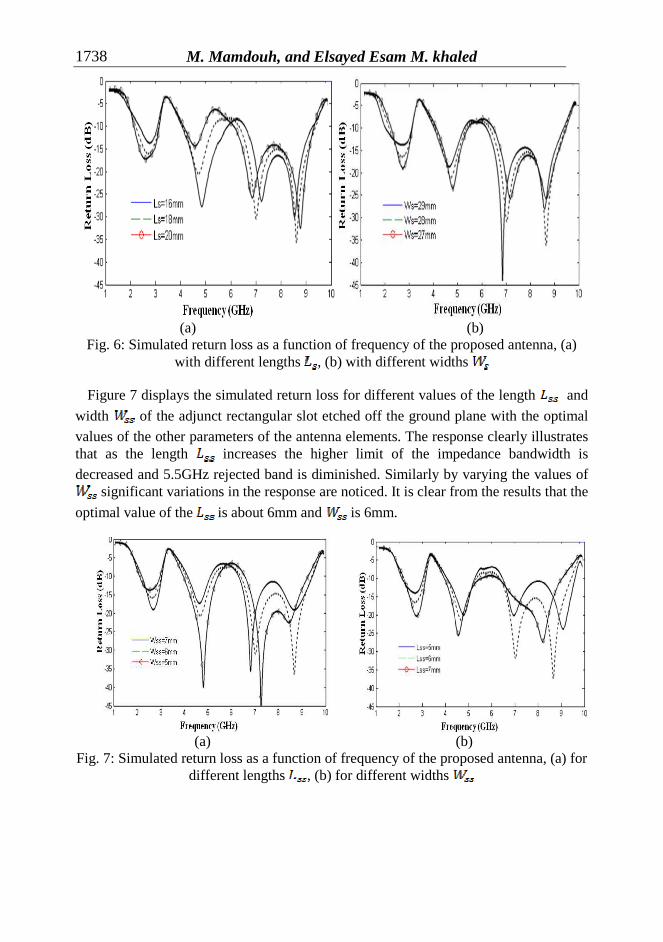
Fig. 6: Simulated return loss as a function of frequency of the proposed antenna, (a) with different lengths , (b) with different widths
Figure 7 displays the simulated return loss for different values of the length and
width of the adjunct rectangular slot etched off the ground plane with the optimal
values of the other parameters of the antenna elements. The response clearly illustrates that as the length increases the higher limit of the impedance bandwidth is
decreased and 5.5GHz rejected band is diminished. Similarly by varying the values of significant variations in the response are noticed. It is clear from the results that the
optimal value of the is about 6mm and is 6mm.
(a) (b)
Fig. 7: Simulated return loss as a function of frequency of the proposed antenna, (a) for different lengths , (b) for different widths
A COMPACT ULTRA-WIDE BAND MICROSTRIP SLOTTED …
1739
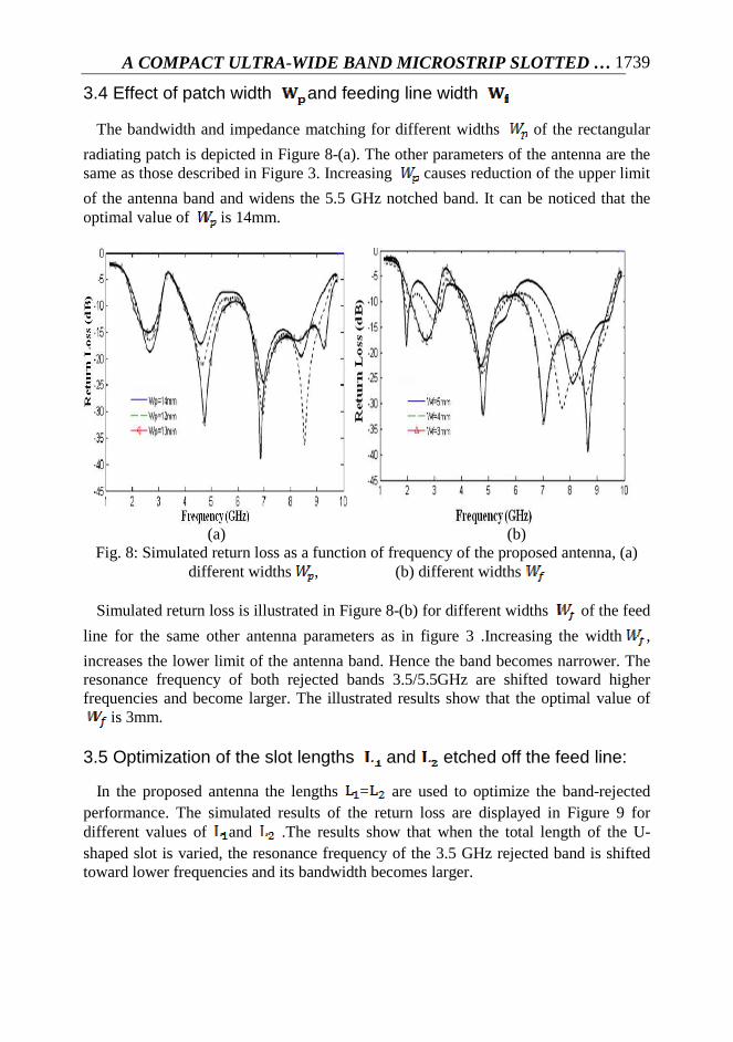
3.4 Effect of patch width and feeding line width
The bandwidth and impedance matching for different widths of the rectangular
radiating patch is depicted in Figure 8-(a). The other parameters of the antenna are the same as those described in Figure 3. Increasing causes reduction of the upper limit
of the antenna band and widens the 5.5 GHz notched band. It can be noticed that the optimal value of is 14mm.
(a) (b)
Fig. 8: Simulated return loss as a function of frequency of the proposed antenna, (a) different widths , (b) different widths
Simulated return loss is illustrated in Figure 8-(b) for different widths of the feed
line for the same other antenna parameters as in figure 3 .Increasing the width ,
increases the lower limit of the antenna band. Hence the band becomes narrower. The resonance frequency of both rejected bands 3.5/5.5GHz are shifted toward higher frequencies and become larger. The illustrated results show that the optimal value of
is 3mm.
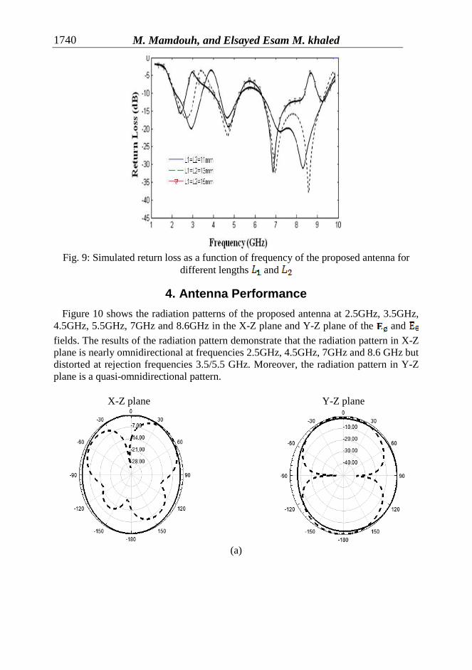
3.5 Optimization of the slot lengths and etched off the feed line:
In the proposed antenna the lengths = are used to optimize the band-rejected performance. The simulated results of the return loss are displayed in Figure 9 for different values of and .The results show that when the total length of the U-shaped slot is varied, the resonance frequency of the 3.5 GHz rejected band is shifted toward lower frequencies and its bandwidth becomes larger.
M. Mamdouh, and Elsayed Esam M. khaled 1740
Fig. 9: Simulated return loss as a function of frequency of the proposed antenna for
different lengths and
4. Antenna Performance
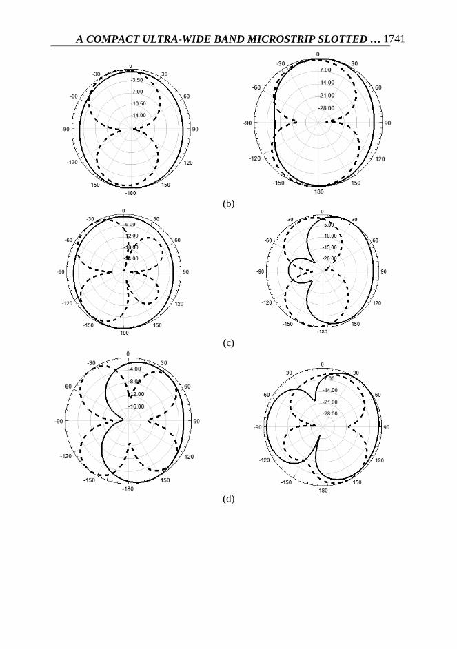
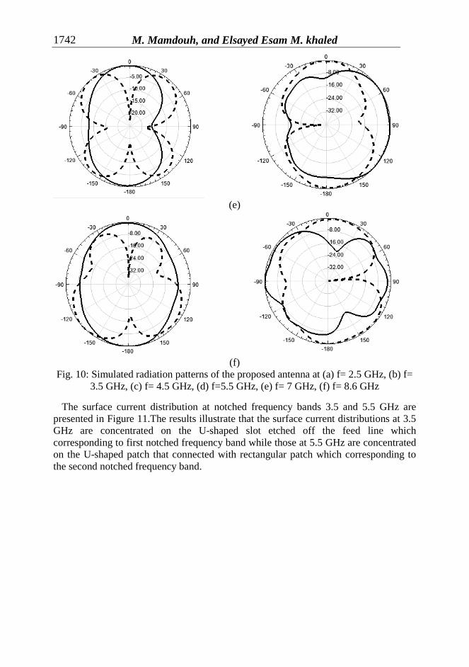
Figure 10 shows the radiation patterns of the proposed antenna at 2.5GHz, 3.5GHz, 4.5GHz, 5.5GHz, 7GHz and 8.6GHz in the X-Z plane and Y-Z plane of the and
fields. The results of the radiation pattern demonstrate that the radiation pattern in X-Z plane is nearly omnidirectional at frequencies 2.5GHz, 4.5GHz, 7GHz and 8.6 GHz but distorted at rejection frequencies 3.5/5.5 GHz. Moreover, the radiation pattern in Y-Z plane is a quasi-omnidirectional pattern.
X-Z plane Y-Z plane
(a)
A COMPACT ULTRA-WIDE BAND MICROSTRIP SLOTTED …
1741
(b)
(c)
(d)
M. Mamdouh, and Elsayed Esam M. khaled 1742
(e)
(f) Fig. 10: Simulated radiation patterns of the proposed antenna at (a) f= 2.5 GHz, (b) f=
3.5 GHz, (c) f= 4.5 GHz, (d) f=5.5 GHz, (e) f= 7 GHz, (f) f= 8.6 GHz
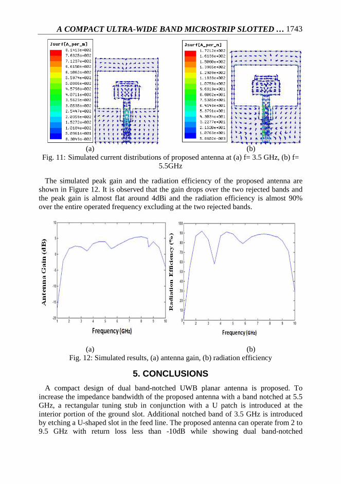
The surface current distribution at notched frequency bands 3.5 and 5.5 GHz are presented in Figure 11.The results illustrate that the surface current distributions at 3.5 GHz are concentrated on the U-shaped slot etched off the feed line which corresponding to first notched frequency band while those at 5.5 GHz are concentrated on the U-shaped patch that connected with rectangular patch which corresponding to the second notched frequency band.
A COMPACT ULTRA-WIDE BAND MICROSTRIP SLOTTED …
1743
(a) (b)
Fig. 11: Simulated current distributions of proposed antenna at (a) f= 3.5 GHz, (b) f= 5.5GHz
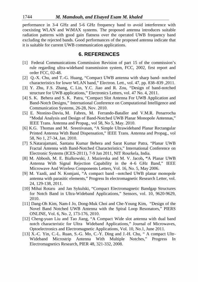
The simulated peak gain and the radiation efficiency of the proposed antenna are shown in Figure 12. It is observed that the gain drops over the two rejected bands and the peak gain is almost flat around 4dBi and the radiation efficiency is almost 90% over the entire operated frequency excluding at the two rejected bands.
(a) (b) Fig. 12: Simulated results, (a) antenna gain, (b) radiation efficiency
5. CONCLUSIONS
A compact design of dual band-notched UWB planar antenna is proposed. To increase the impedance bandwidth of the proposed antenna with a band notched at 5.5 GHz, a rectangular tuning stub in conjunction with a U patch is introduced at the interior portion of the ground slot. Additional notched band of 3.5 GHz is introduced by etching a U-shaped slot in the feed line. The proposed antenna can operate from 2 to 9.5 GHz with return loss less than -10dB while showing dual band-notched
M. Mamdouh, and Elsayed Esam M. khaled 1744
performance in 3-4 GHz and 5-6 GHz frequency band to avoid interference with coexisting WLAN and WiMAX systems. The proposed antenna introduces suitable radiation patterns with good gain flatness over the operated UWB frequency band excluding the rejected bands. Good performances of the proposed antenna indicate that it is suitable for current UWB communication applications.
6. REFERENCES
[1] Federal Communications Commission Revision of part 15 of the commission’s rule regarding ultra-wideband transmission system, FCC, 2002, first report and order FCC, 02-48.
[2] Q.-X. Chu, and T.-G. Huang, “Compact UWB antenna with sharp band- notched characteristics for lower WLAN band,” Electron. Lett., vol. 47, pp. 838–839 ,2011.
[3] Y. Zhu, F.S. Zhang, C. Lin, Y.C. Jiao and R. Zou, “Design of band-notched structure for UWB applications,” Electronics Letters, vol. 47 No. 4, 2011.
[4] S. K. Behera and S. K. Patra, “Compact Slot Antenna For UWB Application and Band-Notch Designs,” International Conference on Computational Intelligence and Communication Systems, 26-28, Nov. 2010.
[5] E. Ntonino-Daviu, M. Fabres, M. Ferrando-Bataller and V.M.R. Penarrocha “Modal Analysis and Design of Band-Notched UWB Planar Monopole Antennas,” IEEE Trans. Antenna and Propag., vol 58, No 5, May. 2010.
[6] K.G. Thomas and M. Sreenivasan, “A Simple Ultrawideband Planar Rectangular Printed Antenna With Band Dispensation,” IEEE Trans. Antenna and Propag., vol 58, No 1, 27-34, Jan. 2010.
[7] S.Natarajamani, Santanu Kumar Behera and Sarat Kumar Patra, “Planar UWB Fractal Antenna with Band-Notched Characteristics,” International Conference on Electronic Systems (ICES-2011), 7-9 Jan 2011, NIT Rourkela, India.
[8] M. Abbosh, M. E. Bialkowski, J. Mazierska and M. V. Jacob, “A Planar UWB Antenna With Signal Rejection Capability in the 4–6 GHz Band,” IEEE Microwave And Wireless Components Letters, Vol. 16, No. 5, May 2006.
[9] M. Yazdi, and N. Komjani, “A compact band –notched UWB planar monopole antenna with parasitic elements,” Progress In electromagnetic Research Letter, vol. 24, 129-138, 2011.
[10] Mihai Rotaru and Jan Sykulski, “Compact Electromagnetic Bandgap Structures for Notch Band in Ultra-Wideband Applications,” Sensors, vol. 10, 9620-9629, 2010.
[11] Dang-Oh Kim, Nam-I Jo, Dong-Muk Choi and Che-Young Kim, “Design of the Novel Band Notched UWB Antenna with the Spiral Loop Resonators,” PIERS ONLINE, Vol. 6, No. 2, 173-176, 2010.
[12] Cheng-yuan Liu and Tao Jiang, “A Compact Wide slot antenna with dual band notch characteristic for Ultra Wideband Applications,” Journal of Microwaves, Optoelectronics and Electromagnetic Applications, Vol. 10, No.1, June 2011.
[13] X.-C. Yin, C.-L. Ruan, S.-G. Mo, C.-Y. Ding and J.-H. Chu, “ A compact Ultr-Wideband Microstrip Antenna With Multiple Notches,” Progress In Electromagnetics Research, PIER 48, 321-332, 2008.
A COMPACT ULTRA-WIDE BAND MICROSTRIP SLOTTED …
1745
[14] Son Trinh-Van and Chien Dao-Ngoc, “Dual Band-Notched UWB Antenna based on Electromagnetic Band Gap Structures,” REV Journal on Electronics and Communications, Vol. 1, No. 2, April – June, 2011.
[15] C. M. Li and L. H. Ye, “Improved Dual Band-Notched UWB Slot Antenna with Controllable Notched Band- Widths,” Progress In Electromagnetics Research, Vol. 115, 477-493, 2011.
[16] K.C.Gupta, Ramesh Garg, Inder Bahl and Prakash Bhartia, Microstrip lines and slotlines, 2nd ed., London, Boston, MA: Artech House, 1996.
ترددىتصميم هوائى ذات الشريحه المتناهى الصغر يعمل فى المدى ال
الفائق وذات قطع ترددى ثنائى
هذا المقال يقدم تصميم بسيط لهوائى شريحه مستوى صغير الحجم ذات المدى الترددى الفائق وله خاصة قطع
المقدم يتكون من خط تغذيه شريحى متناهى و الهوائى . جيجاهرتز 5.5جيجاهرتز و 3.5ترددى ثنائى عند
returnو التصميم يؤدى الى العمل فى نطاق واسع بفقد رجوع . الصغر و فتحتين مستطلتين فى لوحه االرضى
loss و تم زيادة المدى الترددى الذى يعمل فيه . جيجاهرتز 9.5الى 2ديسبل فى مدى التردد من 10-اقل من
جيجاهرتز بواسطه عمل شريحه مستطيله و 5.5جيجاهرتز و 3.5تى القطع عند الهوائى و الحصول على منطق
فى خط التغذيه و القطع الترددى Uوايضآ حفر فتحه على شكل حرف Uمرتبطة بشريحه على شكل حرف
التحسين عرض النطاق الترددى لمعاوقه الهوائى استخدم . جيجاهرتز 5.5جيجاهرتز و 3.5الثنائى عند الترددات
تم عمل دراسات منفصله للعناصر المختلفه شريحه ارضى ذات فتحات و النتوء المتوازى المفتوح فى خط التغذيه
و للتأكد من النتائج النظريه تم تصنيع الهوائى المقترح و قياس النتائج . فى الهوائى لتحديد انسب االبعاد لها
. بينهما العمليه له و مقارنتها بالنتائج النظريه و بين التطابق